EP1193477A1 - Flow rate sensor unit, flowmeter and flow sensor - Google Patents
Flow rate sensor unit, flowmeter and flow sensor Download PDFInfo
- Publication number
- EP1193477A1 EP1193477A1 EP00940780A EP00940780A EP1193477A1 EP 1193477 A1 EP1193477 A1 EP 1193477A1 EP 00940780 A EP00940780 A EP 00940780A EP 00940780 A EP00940780 A EP 00940780A EP 1193477 A1 EP1193477 A1 EP 1193477A1
- Authority
- EP
- European Patent Office
- Prior art keywords
- flow rate
- fluid
- housing
- sensor unit
- detector
- Prior art date
- Legal status (The legal status is an assumption and is not a legal conclusion. Google has not performed a legal analysis and makes no representation as to the accuracy of the status listed.)
- Withdrawn
Links
Images






Classifications
-
- G—PHYSICS
- G01—MEASURING; TESTING
- G01F—MEASURING VOLUME, VOLUME FLOW, MASS FLOW OR LIQUID LEVEL; METERING BY VOLUME
- G01F1/00—Measuring the volume flow or mass flow of fluid or fluent solid material wherein the fluid passes through a meter in a continuous flow
- G01F1/68—Measuring the volume flow or mass flow of fluid or fluent solid material wherein the fluid passes through a meter in a continuous flow by using thermal effects
-
- G—PHYSICS
- G01—MEASURING; TESTING
- G01F—MEASURING VOLUME, VOLUME FLOW, MASS FLOW OR LIQUID LEVEL; METERING BY VOLUME
- G01F1/00—Measuring the volume flow or mass flow of fluid or fluent solid material wherein the fluid passes through a meter in a continuous flow
- G01F1/68—Measuring the volume flow or mass flow of fluid or fluent solid material wherein the fluid passes through a meter in a continuous flow by using thermal effects
- G01F1/696—Circuits therefor, e.g. constant-current flow meters
- G01F1/6965—Circuits therefor, e.g. constant-current flow meters comprising means to store calibration data for flow signal calculation or correction
-
- G—PHYSICS
- G01—MEASURING; TESTING
- G01F—MEASURING VOLUME, VOLUME FLOW, MASS FLOW OR LIQUID LEVEL; METERING BY VOLUME
- G01F1/00—Measuring the volume flow or mass flow of fluid or fluent solid material wherein the fluid passes through a meter in a continuous flow
- G01F1/68—Measuring the volume flow or mass flow of fluid or fluent solid material wherein the fluid passes through a meter in a continuous flow by using thermal effects
- G01F1/684—Structural arrangements; Mounting of elements, e.g. in relation to fluid flow
Definitions
- the present invention relates to a fluid flow rate detecting technique, and particularly to a flowmeter for determining the flow rate or integrated flow rate of fluid such as gas, liquid or the like and a flow rate sensor unit for use in the same, and a flow rate sensor for detecting the flow rate of fluid flowing in a pipe.
- an indirectly heated type flow rate sensor in which a sensor chip having a thin film heater and a thin film temperature sensor laminated on a substrate through an insulating film by using the thin film technique is disposed so that heat can be transferred between the sensor chip and fluid in a pipe.
- the temperature sensor By supplying current to the heater, the temperature sensor is heated to vary the electrical characteristic of the temperature sensor, for example, the value of the electrical resistance.
- the variation of electrical resistance value (based on temperature increase of the temperature sensor) is varied in accordance of the flow rate (flow velocity) of fluid flowing in the pipe.
- the heating value of the heater is transferred into the fluid, the heating value dispersed into the fluid is varied in accordance with the flow rate (flow velocity) of the fluid, and thus the heating value supplied to the temperature sensor is finally varied in accordance with the flow rate (flow velocity) of the fluid, so that the electrical resistance value of the temperature sensor is varied in accordance with the flow rate (flow velocity) of the fluid.
- the variation of the electrical resistance value of the temperature sensor is also different in accordance with the temperature of the fluid, and thus a temperature sensor for temperature compensation is installed in an electrical circuit for detecting the variation of the electrical resistance value of the temperature sensor to suppress the variation of the flow rate measurement value due to the temperature of the fluid as much as possible.
- an indirectly heated type flow rate sensor using a thin film element disclosed in JP(A)-8-146026 which is estimated to be excellent in thermal response, high in measurement precision, compact in size and low in cost, has the following construction.
- a flow rate sensor 501 has a thin film heater 503 and a thin film temperature sensor 504 which are laminated on a substrate 502 through an insulating layer 505 by using the thin film technique, and it is used while disposed at a proper position of a pipe 506 as shown in Fig. 25.
- the temperature sensor 504 is heated by supplying current to the heater 503 to detect the variation of the electrical resistance value of the temperature sensor 504. Since the flow rate sensor 501 is disposed in the pipe 506, a part of the heating value of the heater 503 is dispersed through the substrate 502 to the fluid flowing in the pipe, and thus the heating value transferred to the temperature sensor 504 corresponds to the value achieved by subtracting the dispersed heating value from the heating value of the heater 503. Further, since the dispersed heating value is varied in accordance with the flow rate of the fluid, the flow rate of the fluid flowing in the pipe 506 can be determined by detecting the variation of the electrical resistance value of the temperature sensor 504 which varies in accordance with the heating amount being supplied thereto.
- a temperature sensor 507 is disposed at a proper position of the pipe 506 as shown in Fig. 25, and a temperature compensating circuit is added in the flow rate detecting circuit for detecting the variation of the electrical resistance value of the temperature sensor 504 to reduce the error of the flow rate measurement value due to the temperature of the fluid at maximum.
- the conventional flow rate sensor 501 is directly mounted on the metal pipe 506, and also the metal pipe 506 is exposed to the outside air. Therefore, the heating value of fluid itself is dispersed to the outside air through the metal pipe having high thermal conductivity, or the heating value of the outside air is liable to be supplied to the fluid, resulting in reduction in the measurement precision of the flow rate sensor 501. Particularly when the flow rate of fluid is very low, it has a great effect on the measurement precision, and thus when the temperature difference between the fluid and the outside air is large or when the specific heat of the fluid is small, the effect is more remarkable.
- the flow velocity in the cross-section perpendicular to the flow direction of the fluid in the pipe 506 is largely different between the portion in the neighborhood of the pipe wall and the center portion, and the flow velocity vector exhibits a substantially parabolic distribution having the extreme value at the center portion. That is, the non-uniformity of the flow velocity distribution is remarkable.
- the flow velocity distribution has a large effect on the precision of the flow rate measurement. This is because no consideration is given to the flow velocity of fluid flowing at the central portion in the cross-section of the pipe and consideration is given to only the flow velocity of fluid flowing in the neighborhood of the pipe wall of the pipe.
- the conventional flow rate sensor has a problem that it is difficult to accurately determine the flow rate.
- the flow rate sensor 501 is used under various different environments such as geographical conditions, indoors/outdoors, etc., and various other factors such as season conditions, day/night, etc. are also added particularly outdoors, so that consideration must be given to temperature variation due to external environments.
- the conventional flow rate sensor 501 is designed to be likely influenced by such external environmental temperature, so that the measurement value of the flow rate has a large error. Therefore, a flow rate sensor that can determine the flow rate with high precision under broad external environmental temperature has been required.
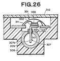
- a flow rate sensor as shown in Fig. 26 has been proposed. This is substantially the same as disclosed in JP(A)-11-118566, for example.
- a flow rate detector 306 having a thin film heater and a thin film temperature sensor which are laminated on a substrate 302 through an insulating layer is mounted on a horizontal portion 307a of a fin plate 307 which is bent in an L-shape, thereby forming a flow rate sensor 301.
- glass 310 is sealingly filled between the vertical portion 307b of the fin plate 307 and the opening portion of a flow pipe 309, and the flow rate detector 306 and the overall horizontal portion 307a of the fin plate 307 are hermetically coated and fixed by synthetic resin 311.
- the upper portion of the casing 308 is covered by a lid 312.
- the flow rate detector 306 and the synthetic resin 311 are directly brought into contact with each other, so that the heating value owned by the temperature sensor flows out to the synthetic resin 311 or the heating value flows from the synthetic resin 311 into the temperature sensor. Further, the flow rate detector 306 is joined to the horizontal portion 307a of the fin plate 307 by joint material 313 of silver paste having excellent thermal conductivity or the like, so that the heating value transferred through the fin plate 307 flows out to the synthetic resin 311 through the joint material 313, or the heating value flows out from the synthetic resin 311 to the fin plate 307. Accordingly, when the specific heat of the fluid is small or when the flow rate is low, the sensitivity of the flow rate sensor 301 may be reduced.
- the glass 310 is filled between the vertical portion 307b of the fin plate 307 and the opening portion of the flow pipe 309 to intercept the thermal transfer.
- the heating value transferred through the fin plate 307 flows out to the casing 308 through the metal flow pipe 309 having excellent thermal conductivity or the heating value flows from the casing 308 into the fin plate 307. Accordingly, when the specific heat of the fluid is small or when the flow rate is low, the sensitivity of the flow rate sensor 301 may be reduced as in the foregoing case.
- the present invention has an object to solve the above problem and provide a flow rate sensor that can suppress flow-in/flow-out of heating value between each part of the flow rate sensor and a casing/the external to determine the flow rate with high precision even when the specific heat of fluid is small, when the flow rate is low, etc., and can be easily fabricated and reduced in cost.
- the flow rate sensor disclosed in the above JP(A)-11-118566 uses an electrical circuit containing a bridge circuit to achieve the electrical output corresponding to the flow rate of fluid.
- the output of the electrical circuit of the flow rate sensor has no simple proportional relationship with the flow rate value. Therefore, in order to convert the output of the electrical circuit to the flow rate value, data processing using a calibration curve may be carried out.
- the data processing is carried out by using a microcomputer, and digital signals indicating the flow rate value may be input to a display device or transmitted to a desired remote place through a communication line.
- the flow rate sensor as described above, it is required to throw the contact portion thereof with fluid and the surrounding portion thereof away periodically or after a predetermined amount of fluid flows.
- the flow rate sensor when the flow rate sensor is applied to determine the flow rate of raw materials in a process of synthesizing high-purity reagent or medicines, throw-away is required from the viewpoint of surely preventing purity-reduction of products due to contamination of impurities.
- throw-away when it is applied to a flow rate measurement of samples in a chemical analysis such as chemical titration or the like, throw-away is required from the viewpoint of preventing an adverse effect on the analysis due to unexpected chemical reactions because the components contained in the samples are unknown.
- throw-away when it is applied to a flow rate measurement of liquid medicines being injected into a living body or a flow rate measurement of a body fluids picked up from a living body, throw-away is required from the viewpoint of preventing disease infection.
- the throw-away portions have been strongly required to be miniaturized in size and reduced in cost. Therefore, it has been considered to unify a thermal conductor to be extended into a fluid flowing pipe, a sensor chip fixed to the thermal conductor and wires connected to the terminals of the sensor chip into a unit as a throw-away portion.
- a common calibration curve is used for plural sensor units in a data processing circuit to convert the output of the electrical circuit to the flow rate value.
- the calibration curve regulates a standard relationship, and no consideration is given to an individual condition of each sensor.
- the orientation of the thermal conductor to be extended to the external, the joint state between the sensor chip and the thermal conductor, the connection state between the sensor chip and the wires are minutely varied every sensor unit, and thus the relationship between the flow rate supporting output and the flow rate value is frequently varied every sensor unit.
- a measurement error occurs in the flow rate measurement due to the individual difference among sensor units, and thus the measurement precision is reduced.
- an object of the present invention is to provide a flow rate sensor unit which can suppress occurrence of a flow rate measurement error due to the individual difference of sensor units.
- Another object of the present invention is to provide a flowmeter which can suppress occurrence of a flow rate measurement error due to the individual difference of sensor units.
- a flow rate sensor unit in which a flow rate detector having a heater and a flow rate detecting temperature sensor is joined to a flow rate detecting thermal conductor, and the flow rate detector and a part of the flow rate detecting thermal conductor are accommodated in a housing, characterized in that the housing encloses a memory for storing individual information of the flow rate sensor unit used when a flow rate value is achieved on the basis of a detection signal of a detecting circuit containing the heater and the flow rate detecting temperature sensor, and the flow rate detector and the memory are connected to plural leads in the housing, the plural leads being partially exposed to the outside of the housing.
- a fluid temperature detector containing a fluid temperature detecting temperature sensor is joined to a fluid temperature detecting thermal conductor, the housing encloses the fluid temperature detector and a part of the fluid temperature detecting thermal conductor, the detecting circuit contains the fluid temperature detecting temperature sensor, and in the housing the fluid temperature detector is connected to plural leads which are partially exposed to the outside of the housing.
- the individual information stored in the memory is correction information for a standard calibration curve used when the flow rate value is achieved on the basis of the detection signal ofthe detecting circuit.
- a fluid channel is connected to the housing, and the other part of the flow rate detecting thermal conductor extends into the fluid channel.
- a fluid channel is connected to the housing, and the other part of the fluid temperature detecting thermal conductor extends into the fluid channel.
- a flowmeter including the above flow rate sensor unit and an electrical circuit portion connected to the leads of the flow rate sensor unit, wherein the electrical circuit portion achieves the fluid flow rate value on the basis of the detection signal of the detecting circuit by referring to a standard calibration curve stored in advance, and at that time corrects the standard calibration curve by using the individual information stored in the memory of the flow rate sensor unit.
- the electrical circuit portion includes an analog circuit portion for achieving the output corresponding to the flow rate of the fluid by using the detection signal of the detecting circuit, and a digital circuit portion for achieving the fluid flow rate value on the basis of the output of the analog circuit, and the digital circuit portion includes a microcomputer and a main memory for storing the standard calibration curve.
- the individual information stored in the memory of the flow rate sensor unit reflects plural relationships between the output value corresponding to the fluid flow rate actually-measured for the flow rate sensor unit and the true fluid flow rate value.
- the leads of the flow rate sensor unit and the electrical circuit portion are detachably connected to each other.
- a flow rate sensor unit in which a flow rate detector having a heater and a flow rate detecting temperature sensor is joined to a flow rate detecting thermal conductor, and the flow rate detector and a part of the flow rate detecting thermal conductor are accommodated in a housing, characterized in that a fluid channel is connected to the housing, the other part of the flow rate detecting thermal conductor extends into the fluid channel, a thermal conductor extending from the inside of the housing into the fluid channel is disposed, the housing encloses a memory for storing individual information of the flow rate sensor unit used when a flow rate value is achieved on the basis of a detection signal of a detecting circuit containing the heater and the flow rate detecting temperature sensor, and the flow rate detector and the memory are connected to plural leads in the housing, the plural leads being partially exposed to the outside of the housing.
- a fluid temperature detector containing a fluid temperature detecting temperature sensor is joined to a fluid temperature detecting thermal conductor, the housing encloses the fluid temperature detector and a part of the fluid temperature detecting thermal conductor, the other part of the fluid temperature detecting thermal conductor extends into the fluid channel, the detecting circuit contains the fluid temperature detecting temperature sensor, and in the housing the fluid temperature detector is connected to plural leads which are partially exposed to the outside of the housing.
- the individual information stored in the memory is correction information for a standard calibration curve used when the flow rate value is achieved by using the detection signal of the detecting circuit.
- the thermal conductor extends to be nearer to the portions of the leads in the housing than the flow rate detecting thermal conductor. In an aspect of the present invention, the thermal conductor extends to be nearer to the portions of the leads in the housing than the fluid temperature detecting thermal conductor.
- the memory is joined to the thermal conductor.
- the flow rate detecting thermal conductor, the fluid temperature detecting thermal conductor and the thermal conductor are designed in a plate shape, and arranged along the direction of the fluid channel on the same plane in the fluid channel.
- a flowmeter containing the above flow rate sensor unit and an electrical circuit portion connected to the leads of the flow rate sensor unit, wherein the electrical circuit portion achieves the fluid flow rate value on the basis of the detection signal of the detecting circuit by referring to a standard calibration curve stored in advance, and at that time corrects the standard calibration curve by using the individual information stored in the memory of the flow rate sensor unit.
- the electrical circuit portion includes an analog circuit portion for achieving the output corresponding to the flow rate of the fluid by using the detection signal of the detecting circuit, and a digital circuit portion for achieving the fluid flow rate value on the basis of the output of the analog circuit, and the digital circuit portion includes a microcomputer and a main memory for storing the standard calibration curve.
- the individual information stored in the memory of the flow rate sensor unit reflects plural relationships between the output value corresponding to the fluid flow rate actually-measured for the flow rate sensor unit and the true fluid flow rate value.
- the leads of the flow rate sensor unit and the electrical circuit portion are detachably connected to each other.
- a flow rate sensor comprising a flow rate measuring portion for detecting the flow rate of fluid, a temperature compensating measuring portion for compensating an effect of fluid temperature on measurements of the flow rate measuring portion, and a housing
- the flow rate measuring portion includes a flow rate detector having a heater and a temperature sensor laminated each other through an insulator, a fin plate joined to the flow rate detector at one end thereof, and an output terminal electrically connected to the flow rate detector
- the temperature compensating measuring portion includes a temperature detector having an insulator and a temperature sensor that are laminated on each other, a fin plate joined to the temperature detector at one end thereof, and an output terminal electrically connected to the temperature detector
- the housing encloses the flow rate detector and the temperature detector therein, and the fin plates and the output terminals of the flow rate measuring portion and the temperature compensating measuring portion are projected to the outside of the housing.
- the housing is preferably formed of synthetic resin having thermal conductivity of 0.7W/m ⁇ K or less.
- a cavity portion is provided in the housing, and the flow rate detector and the temperature detector are mounted at a position of the cavity portion at which the flow rate detector and the temperature detector are not brought into contact with the housing.
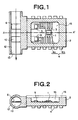
- Fig. 1 is a schematic cross-sectional view showing an embodiment of a flow rate sensor unit according to the present invention
- Fig. 2 is a cross-sectional view taken along A-A' of Fig. 1.
- a flow rate detector 5 is joined on the surface of a fin plate 6 serving as a flow rate detecting thermal conductor
- a fluid temperature detector 9 is joined on the surface of a fin plate 10 serving as a fluid temperature detecting thermal conductor.
- the flow rate detector 5, the fluid temperature detector 9 and a part of each of the fin plates 6, 10 are accommodated in a housing 2.
- the flow rate detector 5 is designed in the form of a chip by laminating a flow rate detecting thin film temperature sensor 31, an interlayer insulating film 32, a thin film heater 33, electrodes 34, 35 for the heater and a protection film 36 in this order on a rectangular substrate 30 of about 0.4mm in thickness and about 2mm in square which is formed of silicon or alumina, for example, and then forming a pad layer 37 coated on the bonding portion of the flow rate detecting thin film temperature sensor 31 and the heater electrodes 34, 35.
- the thin film temperature sensor 31 may be a metal resistance film of platinum (Pt) or nickel (Ni) having a large and stable temperature coefficient which is patterned in a desired form, for example in a meandering form so as to have a film thickness of about 0.5 to 1 ⁇ m. Alternatively, it may be an NTC thermistor of manganese oxide group.
- the interlayer insulating film 32 and the protection film 36 may be formed of SiO 2 at a thickness of about 1 ⁇ m, for example.
- the thin film heater 33 may comprise a resistor of Ni, Ni-Cr, Pt, or cermet such as Ta-SiO 2 , Nb-SiO 2 or the like, which is patterned to have a desired shape and a film thickness of about 1 ⁇ m.
- the heater electrodes 34, 35 may be formed of an Ni layer having a thickness of about 1 ⁇ m or a laminate of the Ni layer and a gold (Au) layer of 0.5 ⁇ m laminated thereon.
- the pad layer 37 may be formed of an Au thin film or Pt thin film having a thickness of about 0.1 ⁇ m and a size of 0.2mm x 0.15mm in longitudinal and lateral directions.
- the fluid temperature detector 9 has the same construction as the flow rate detector 5 except that the thin film heater 33, etc. are removed from the flow rate detector 5, that is, it is designed in a chip form by laminating a fluid temperature detecting thin film temperature sensor 31' having the same construction as the thin film temperature sensor 31 and a protection film 36' having the same construction as the protection film 36 in this order on a substrate 30' having the same construction as the substrate 30, and then forming a pad layer 37' so as to cover the bonding portion of the fluid temperature detecting thin film temperature sensor 31'.
- the fin plate 6, 10 may be a rectangular plate of about 0.2mm in thickness and about 2mm in width, which is formed of, copper, duralumin, copper-tungsten alloy or the like. Silver paste may be used as the joint material.
- a fluid channel member 12 is connected to the housing 2 of a sensor unit, and the other end portions of the fin plates 6, 10 extend into a fluid channel 13 formed in the fluid channel member 12.
- the fin plates 6, 10 extend in the fluid channel 13 having the substantially circular cross-section so as to pass through the center of the cross-section of the fluid channel 13.
- the fin plates 6, 10 are disposed along the fluid flowing direction (indicated by an arrow of Fig. 1) in the fluid channel 13. Therefore, they can excellently perform thermal transfer (thermal conduction) between the fluid and each of the flow rate detector 5 and the fluid temperature detector 9 without significantly disturbing the flow of fluid in the fluid channel 13.
- the housing 2 and the fluid channel member 12 may be formed of synthetic resin such as epoxy resin, polyphenylene sulfide resin or the like.
- a chip-shaped semiconductor memory 1 for storing individual information of the sensor unit is accommodated in the housing 2. The individual information stored in the memory 1 will be described later.
- Each electrode terminal (pad) of the flow rate detector 5, the fluid temperature detector 9 and the memory 1 is connected to the inner lead portion (each portion in the housing) 4a of each lead 4 by an Au wire 3.
- Each lead 4 extends to the outside of the housing 2 and is partially exposed to the outside of the housing to thereby form an outer lead portion 4b.
- the outer lead portion 4b may be of a J-bent type, for example.
- a space 15 is formed at the center portion of the housing 2, and the detectors 5, 9, parts of the fin plates 6, 10 and the inner lead portions 4a are located in the space 15.
- the space 15 is covered by a cover 16 which is formed integrally with the housing 2, or sealed with synthetic resin so that it is integrated with the housing 2.
- FIG. 5 and 6 A modification of the flow rate sensor unit thus constructed will be described with reference to Figs. 5 and 6.
- the members and portions having the same functions as those of Figs. 1 and 2 are represented by the same reference numerals.
- This modification is different from the construction shown in Figs. 1 and 2 only in that the housing 2 is formed integrally with the fluid channel member 12 in the same molding process.
- Fig. 7 shows an embodiment of a flowmeter using the flow sensor unit as described above.
- a socket 20 is fitted to the outer lead portions 4b exposed to the outside of the housing 2 of the sensor unit, and wires 21 are connected to the socket 20.
- Each of the wires is electrically connected to each outer lead portion 4b at one end thereof, and also connected to an electrical circuit portion 22 at the other end thereof.
- the electrical circuit portion 22 has an analog circuit portion 23, a digital circuit portion 24 and a display portion 25, the wires 21 are connected to the analog circuit portion 23, and the output of the analog circuit portion 23 is input to the digital circuit portion 24.
- the digital circuit portion 24 is connected to the display portion 25 and a communication line for communications with the external.
- Fig. 8 shows a modification of the connection between the flow rate sensor unit as described above and the electrical circuit portion.
- a modular jack 26 is interposed at some midpoint of the wires 21, and the wires 21 can be separated into the sensor unit side wiring portion 21a and the electrical circuit side wiring portion 21b by the modular jack 26. Accordingly, the wiring portion 21a, the socket 20 and the flow rate sensor unit secured to the socket can be removed from the wiring portion 21b by the modular jack 26 while keeping the connection between the housing 2 and the socket 20. Accordingly, the wiring portion 21a and the socket 20 can be discarded together with the flow rate sensor unit.
- This construction increases the number of parts to be thrown away, however, there is avoided the variation imposed on the extension state of the fin plates 6, 10 into the fluid channel in such a case that the housing 2 is mounted onto the socket 20, and thus the attaching/detaching operation can be easily performed.
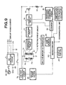
- Fig. 9 is a circuit diagram of the above flowmeter.
- AC 100V is used as a power supply source, and DC voltages of +15V, -15V, +5V generated from AC 100V are output by a DC converting circuit 71.
- the DC voltage of +15V output from the DC converting circuit 71 is input to a voltage stabilizing circuit 72.
- the stabilized DC voltage supplied from the voltage stabilizing circuit 72 is supplied to a bridge circuit (detection circuit) 73.
- the bridge circuit 73 comprises a flow rate detecting temperature sensor 31, a temperature compensating temperature sensor 31', a resistor 74 and a variable resistor 75.
- the potentials Va, Vb at a, b points of the bridge circuit 73 are input to a differential amplifying circuit 76 having variable amplification factor.
- the output of the differential amplifying circuit 76 is input to an integrating circuit 77.
- the output of the voltage stabilizing circuit 72 is supplied to a thin film heater 33 through an electric field effect transistor 81 for controlling the current supplied to the thin film heater 33. That is, in the flow rate detector 5, on the basis of the heating of the thin film heater 33, the temperature sensing operation of the thin film temperature sensor 31 is carried out while suffering an effect of endothermic action of fluid to be examined through the fin plate 6. As a result of the temperature sensing, the difference between the potentials Va, Vb at the a, b points of the bridge circuit 73 shown in Fig. 9 is achieved.
- the temperature of the flow rate detecting temperature sensor 31 is varied in accordance with the flow rate of fluid, and the variation of the temperature of the flow rate detecting temperature sensor 31 causes variation of the value (Va-Vb).
- the value of (Va-Vb) can be set to zero when the flow rate of the fluid is equal to a desired value (reference value).
- the output of the differential amplifying circuit 76 is equal to zero, and the output of the integrating circuit 77 is equal to a fixed value (the value corresponding to the reference flow rate).
- the output of the integrating circuit 77 is subjected to level adjustment so that the minimum value is equal to 0V.
- the output of the integrating circuit 77 is input to a V/F converting circuit 78, in which a pulse signal having the frequency (for example, 5x10 -5 at maximum) corresponding to a voltage signal is formed.
- the pulse signal has a fixed pulse width (time interval) (for example, a desired value in the range from 1 to 10 ⁇ sec). For example, when the output of the integrating circuit 77 is equal to 1V, a pulse signal having a frequency of 0.5 kHz is output, and when the output of the integrating circuit 77 is equal to 4V, a pulse signal having a frequency of 2 kHz is output.
- the output of the V/F converting circuit 77 is supplied to the gate of the transistor 81.
- Current flows into the thin film heater 33 through the transistor whose gate is supplied with the pulse signal.
- a divided voltage of the output voltage of the voltage stabilizing circuit 72 is applied to the thin film heater 33 through the transistor at the frequency corresponding to the output value of the integrating circuit 77 and in the pulse form, whereby current intermittently flows into the thin film heater 33 to heat the thin film heater 33.
- the frequency of the V/F converting circuit 77 is set on the basis of a high-precision clock which is set on the basis of oscillation of a temperature compensated type quartz oscillator 79 in a reference frequency generating circuit 80.
- the analog circuit portion 23 is constructed to contain the above elements.
- the pulse signal output from the V/F converting circuit 77 is counted by a pulse counter 82.
- a microcomputer 83 converts the result to the corresponding flow rate (instantaneous flow rate), and integrates the flow rate thus achieved with respect to time to thereby calculate an integrated flow rate.
- the conversion to the flow rate is carried out by using a standard calibration curve stored in the main memory 84 in advance.
- Fig. 10 shows an example of the calibration curve. That is, a data table achieved by measuring the pulse frequency output from the pulse counter 82 every flow rate of fluid by using a flow rate sensor unit as a reference sensor unit is stored as a standard calibration curve in the main memory 84.
- individual information of a sensor unit for flow rate measurements is stored in the memory 1 of the sensor unit concerned.
- the individual information is data indicating plural corresponding relationships between the true flow rate value and the output pulse frequency of the pulse counter 82 achieved in advance by actually measuring the flow rate with the sensor unit concerned.
- a standard calibration curve SL is shown in Fig. 11.
- the standard calibration curve SL shows the relationship between a flow rate value x and a pulse frequency value y.
- the relationship of (flow rate value - pulse frequency value) at points P, Q in Fig. 11, that is, P(x 1 , y 1 ) and Q(x 2 , y 2 ) are stored in the built-in memory 1 of the sensor unit.
- the data storage into the memory 1 as described above may be carried out as follows. That is, EEPROM is used as the memory 1, under the existence of the space 15 as shown in Figs. 1 and 2 (that is, before the resin sealing and provision of the cover 16), fluid is made flow at flow rate values of x 1 and x 2 to measure the output pulse frequency values y 1 and y 2 , and these measurement values are written into EEPROM by laser irradiation. After the individual information is stored into the memory 1 as described above, the space 15 is sealed with resin or the cover 16 is mounted on the space 15, thereby completing the sensor unit. With this process, the sensor unit containing the memory 1 can be manufactured in low cost.
- the memory 1 of the present invention is not limited to EEPROM, and different kinds of writable memories may be used.
- the standard calibration curve is first corrected on the basis of the individual information as described above to create a corrected calibration curve. That is, a corrected calibration curve CL passing through (x 1 , y 1 ) and (x 1 , y 2 ) is achieved on the basis of the standard calibration curve SL as shown in Fig. 11 and the individual information P(x 1 , y 1 ) and Q (x 2 , y 2 ). Specifically, when the pulse frequency value is equal to y 1 , the corrected flow rate value is set to the sum of the flow rate value x and the correction value [containing sign] C(y 1 ), i.e., [x + C(y 1 )].
- the corrected flow rate value is set to the sum of the flow rate value x and the correction value [containing sign] C(y 2 ), that is, [x + C(y 2 )].
- the correction value C(y) may be set by the extrapolating or interpolating method, for example.
- the individual information comprises two points P(x 1 , y 1 ) and Q(x 2 , y 2 ), however, the corrected calibration curve CL can be further easily achieved by setting the individual information to three or more points.
- the microcomputer 83 specifies as a measurement value the corrected flow rate value on the corrected calibration curve CL corresponding to the pulse frequency output from the pulse counter 82 when the flow rate measurement is carried out (the reference flow rate value may be achieved by using the standard calibration curve and then added with the correction value C(y) as described above).
- the digital circuit portion 30 is constructed by containing the above elements.
- the values of the instantaneous flow rate and the integrated flow rate thus achieved are displayed on the display portion 25, and also transmitted to the external through a communication line such as a telephone line or other network. If necessary, the data of the instantaneous flow rate and the integrated flow rate may be stored in the main memory 84.
- Reference numeral 85 represents a backup power source (for example, battery).
- the polarity which is different in accordance with the positive/negative sign of the resistance-temperature characteristic of the flow rate detecting temperature sensor 31
- magnitude of the output of the differential amplifying circuit 76 is varied in accordance with the value of (Va-Vb)
- the output of the integrating circuit 77 is also varied in accordance with the above variation.
- the variation velocity of the output of the integrating circuit 77 may be adjusted by setting the amplification factor of the differential amplifying circuit 76.
- the response characteristic of the control system is set by the integrating circuit 77 and the differential amplifying circuit 76.
- the temperature of the flow rate detecting temperature sensor 31 is reduced. Therefore, such an output (a higher voltage value) of the integrating circuit 77 as increases the heating value of the thin film heater 33 (that is, increases the pulse frequency) is achieved, and the bridge circuit 73 is set to an equilibrium state at the time point when the output of the integrating circuit is equal to the voltage corresponding to the flow rate of the fluid.
- the temperature of the flow rate detecting temperature sensor 31 increases, so that such an output (a lower voltage value) of the integrating circuit 77 as reduces the heating value of the thin film heater 33 (that is, reduces the pulse frequency) is achieved, and the bridge circuit 73 is set to the equilibrium state at the time point when the output of the integrating circuit is equal to the voltage corresponding to the fluid flow rate.
- the frequency of the pulse-shaped current (corresponding to the heating value) to be supplied to the thin film heater 33 is set so that the bridge circuit 73 is set to the equilibrium state, and such an equilibrium state as described above (response of the control system) can be realized within 0.1 second, for example.
- the standard calibration curve is corrected on the basis of the individual information of a newly used flow rate sensor unit. Therefore, even when the joint state between the chip of each of the flow rate detector 5 and the fluid temperature detector 9 and the corresponding thermal conductor, the wire bonding connection state between the chip of each of the flow rate detector 5 and the fluid temperature detector 9 and the leads, etc. are different among individual flow rate sensor, the flow rate measurement can be performed with high precision by each flow rate sensor unit. Accordingly, even when the electrical circuit portion of the flowmeter is continuously used and the flow rate sensor unit is thrown away, the high measurement precision can be kept, and the field to which the flow rate measurement is applied can be enlarged.
- the pulse signal generated by the V/F converting circuit 78 is used, and the error due to temperature variation can be sufficiently reduced for the pulse signal, and thus the error of the flow rate value and the integrated flow rate value achieved on the basis of the pulse frequency can be reduced.
- the control of current to be supplied to the thin film heater 33 is carried out on the basis of the ON-OFF operation based on the pulse signal generated in the V/F converting circuit 78, so that a control error due to temperature variation occurs with extremely small probability.
- a minute chip containing a thin film heater and a thin film temperature sensor is used as a flow rate detector, so that high-speed response can be implemented and the precision of the flow rate measurement can be enhanced.
- the temperature of the flow rate detecting temperature sensor 31 around the thin film heater 33 is set to a substantially constant value, so that deterioration of the flow rate sensor unit with time can be suppressed and occurrence of ignition explosion of combustible fluid to be examined can be prevented.
- Fig. 12 is a schematic cross-sectional view showing an embodiment of a flow rate sensor unit according to the present invention
- Fig. 13 is a cross-sectional view taken along A-A' of Fig. 12.
- the members and portions having the same functions as those of Figs. 1 and 2 are represented by the same reference numerals.
- This embodiment is substantially different from the embodiment of Figs. 1 and 2 in that fin plates 17, 18 serving as a thermal conductor are disposed.
- the fin plates 17, 18 are partially accommodated in the housing 2.
- the flow rate detector 5 is designed in the form of a chip as shown in Fig. 3.
- the fluid temperature detector 9 is designed in the form of a chip as shown in Fig. 4.
- the fluid channel member 12 is connected to the housing 2 of the sensor unit, and the end portions of the fin plates 6, 10, 17, 18 extend to the inside of the fluid channel 13 formed in the fluid channel member 12.
- the fin plates 6, 10, 17, 18 extend in the fluid channel 13 having a substantially circular cross-section so as to pass the center of the cross-section of the fluid channel 13. Since the fin plates 6, 10, 17, 18 are arranged along the fluid flowing direction (indicated by an arrow of Fig. 12) in the fluid channel 13, the thermal conduction through the fin plates 6, 10 between each of the flow rate detector 5 and the fluid temperature detector 9 and the fluid and the thermal conduction through the fin plates 17, 18 between the inside of the housing and the fluid can be excellently performed.
- the fin plates 17, 18 may be formed of the same material as the fin plates 6, 10, and the fin plates 17, 18 can be formed together with the fin plates 6, 10 and the leads 4 by patterning a plate-shaped member.
- the fin plate 17 is formed so as to extend to the gap between the inner lead portion 4a and the flow rate detector 5 in the housing 2, that is, it extends to a position nearer to the inner lead portion 4a than the flow rate detector 5.
- the fin plate 18 is formed so as to extend to the gap between the inner lead portion 4a and the fluid temperature detector 9 in the housing 2, that is, it extends to a position nearer to the inner lead portion 4a than the fluid temperature detector 9.
- the wires 3 are arranged so as to stride over the end portions of the fin plates 17, 18 in the housing, so that insulating films 17', 18' can be formed on the end portions of the fin plates 17, 18 to avoid the contact between the wires 3 and the fin plates 17, 18.
- the insulating films 17', 18' may be omitted.
- the thermal conduction between the fluid flowing in the fluid channel 13 and the inside of the housing 2 (particularly, the areas between the inner lead portion 4a and the flow rate detector 5 and between the inner lead portion 4a and the fluid temperature detector 9) can be excellently performed, and even when heat flow occurs between the inside and the outside of the housing 2 through the leads 4, the flow rate detector 5 and the fluid temperature detector 9 can be effectively prevented from being influenced by the heat flow. Particularly, heat flowing into the housing 2 through the leads 4 can be effectively leaked to the fluid in the fluid channel 13.
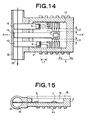
- FIG. 14 and 15 A modification of the flow rate sensor unit as described above is shown in Figs. 14 and 15.
- the members and portions having the same functions as those of Figs. 12 and 13 are represented by the same reference numerals.
- the fin plate 19 serving as a thermal conductor is disposed at the intermediate position between the fin plates 6, 10.
- the memory 1 is connected to the end portion of the fin plate 19 located in the housing.
- the inner lead portion 4a is located at a distance of L1 from the end portions of the fin plates 6, 10 located in the housing, and the distance L2, L3 between the inner lead portion 4a and the end portion of the fin plate 19 located in the housing is set to a distance smaller than L1.
- the distance L1 is set to 3mm or more, and the distances L2, L3 are set to a value less than 3mm.
- the thermal conduction between the fluid flowing in the fluid channel 13 and the inside of the housing 2 is excellently performed, and even when heat flow occurs between the inside and the outside of the housing 2 through the leads 4, the flow rate detector 5 and the fluid temperature detector 9 can be effectively prevented from being influenced by the heat flow.
- the housing 2 and the fluid channel member 12 can be integrally formed with each other in the same molding process.
- a flowmeter can be constructed by using the flow rate sensor unit as described above in the same manner as described with reference to Fig. 7.
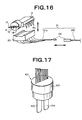
- Fig. 16 shows a modification of the connection between the flow rate sensor unit as described above and the electrical circuit portion. This modification has the same connection as shown in Fig. 8 except that the flow rate sensor unit having the fin plates 17, 18 is used.
- This arrangement can suppress variation imposed on the extension state of the fin plates 6, 10, 17, 18 in the fluid channel in such a case that the housing 2 is mounted onto the socket 20, so that the attaching/detaching operation can be easily performed.
- the circuit construction of the flowmeter as described above is the same as described with reference to Fig. 9.
- the standard calibration curve which is used for the conversion to the flow rate in the flowmeter and stored in the main memory 84 in advance is the same as described with reference to Fig. 10.
- the recording operation of the individual information of the sensor unit into the memory 1 of the sensor unit concerned and the flow rate measuring process of the fluid to be examined which is carried out in the microcomputer 83 by using the individual information are the same as described on the embodiment of Figs. 1 and 2 with reference to Fig. 11.
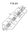
- Fig. 17 is a perspective view showing an embodiment of a flow rate sensor according to the present invention.
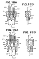
- Fig. 18A is a longitudinally-sectional view showing the flow rate sensor of Fig. 17, and
- Fig. 18B is a longitudinally-sectional view taken along X-X line of Fig. 18A.
- a flow rate sensor 101 comprises a housing 102, a flow rate measuring portion 103 and a temperature compensating measuring portion 104.
- the flow rate measuring portion 103 comprises a flow rate detector 105 mounted in the housing 102, a fin plate 106 which is joined to the flow rate detector 105 at one end thereof and extends to the outside of the housing 102 at the other end thereof, and bonding wires 108 for electrically connecting the flow rate detector 105 to output terminals 107 each of which is joined to each bonding wire 108 at one end thereof and extends to the outside of the housing 102 at the other end thereof.
- the temperature compensating measuring portion 104 comprises a temperature detector 109 mounted in the housing 102, a fin plate 110 which is joined to the flow rate detector 109 at one end thereof and extends to the outside of the housing 102 at the other end thereof, and bonding wires 112 for electrically connecting the temperature detector 109 to output terminals 111 each of which is joined to each bonding wire 112 at one end thereof and extends to the outside of the housing 102 at the other end thereof.
- the flow rate sensor shown in Figs. 18A and 18B has such a structure that no cavity portion is provided in the housing 102 and the surrounding portion of the flow rate detector 105 and the temperature detector 109 are filled with resin.
- synthetic resin having small thermal conductivity as the material of the housing 102. Specifically, if the thermal conductivity is set to 0.7W/m ⁇ K or less, preferably 0.4W/m ⁇ K or less, the heat conduction amount in the housing 102 can be reduced and thus the flow rate can be measured with high precision.
- Figs. 19A and 19B show another embodiment of the flow rate sensor of the present invention.
- a cavity portion is provided in the housing.
- Fig. 19A is a longitudinally-sectional view of the flow rate sensor
- Fig. 19B is a longitudinally-sectional view taken along X-X line of Fig. 19A.
- the flow rate sensor 121 is disposed in the cavity portion 123 of the housing 122 so that both of the flow rate detector 105 of the flow rate measuring portion 103 and the temperature detector 109 of the temperature compensating measuring portion 104 are not brought into contact with the resin forming the housing 122.
- the output terminals 107, 111 are fixed to the wall of the housing 122.
- the thermal transfer between each part of the flow rate sensor and the structure (casing) surrounding the flow rate sensor can be suppressed at maximum by the adiabatic effect of the cavity portion 123.
- a notch portion is formed on the outer peripheral surface of the flow rate sensor so that an adiabatic gap occurs between the flow rate sensor and the casing, heat transfer between the flow rate sensor and the casing can be effectively suppressed.
- the housing 102 is preferably formed of rigid resin having high chemical resistance and high oil resistance, and more preferably formed of resin having low thermal conductivity such as epoxy resin, polybutylene terephthalate (PBT), polyphenylene sulfide (PPS) or the like.
- resin having low thermal conductivity such as epoxy resin, polybutylene terephthalate (PBT), polyphenylene sulfide (PPS) or the like.
- the output terminals 107, 111 are linear thin plates of about 200 ⁇ m in thickness which are formed of material having high conductivity such as copper or the like.
- the output terminals 107, 111 are juxtaposed with one another on a line so as to project to the outside of the resin housing 102 and so that the projection length thereof from the resin housing 102 is gradually increased (reduced) from one end of the linear line to the other end thereof.
- This construction facilitates the mounting work of a sensor press plate for pressing the flow rate sensor 101 from the upper side and a flow rate detecting circuit board which is connected to the output terminals 107, 111 to form a circuit, and also reduces such a risk that the flow rate sensor 101 is damaged when the sensor press plate or the flow rate detecting circuit board is mounted.
- the end portions of the output terminals 107, 111 located in the housing are assembled so as to be proximate to one another, thereby facilitating the work of connecting the bonding wires 108, 112 to the output terminals 107, 111, the flow rate detector 105 and the temperature detector 109.
- Each of the fin plates 106, 110 comprises a rectangular thin plate of about 200 ⁇ m in thickness and about 2mm in width which is formed of material having high thermal conductivity such as copper, duralumin, copper-tungsten alloy or the like.
- the fin plates 106, 110 are fixed to the flow rate detector 105 and the temperature detector 109 through joint material such as silver paste or the like.
- the flow rate detector 105 has the same construction as the flow rate detector 5 described above with reference to Fig. 3.
- the temperature compensating measuring portion 104 has the same construction as the fluid temperature detector 9 described above with reference to Fig. 4
- the fin plate 106 and the output terminals 107, and the fin plate 110 and the output terminals 111 may be respectively formed from a single body.
- a plate raw material 138 is successively etched to form plate bases 139 each having a desired shape (S1), a silver plating treatment is conducted on the portion to which the flow rate detector 105 will be joined (S2), silver paste is coated to fix the flow rate detector 105, the flow rate detector 105 and each of the output terminals 107 are connected to each other by the boding wires 108, and then nickel plating treatment is conducted on the portion corresponding to the fin plate 106 (S3).
- the flow rate detector 105, the upper half portion of the fin plate 106 and the lower half portions of the output terminals 107 are molded by epoxy resin to form the housing 102 (S4), thereby manufacturing the flow rate sensor 101.
- the same process as the case where the fin plate 106 and the output terminals 107 are formed from a single body at the same time is carried out except that the temperature detector 109 is used in place of the flow rate detector 105.
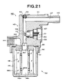
- the flow rate sensor 101 of the present invention is used while inserted and fitted in a strainer-installed type flowmeter 140 as shown in Figs. 21 and 22.
- the strainer-installed type flowmeter 140 is achieved by integrating a strainer portion 142 and a flowmeter portion 143 into one body while a casing 141 is commonly used.
- the casing 141 is achieved by die-casting aluminum, zinc, tin alloy or the like.
- Connecting portions 144, 145 are formed at both the end portions of the casing 141 to connect the casing 141 to external pipes, and a flow-in side fluid channel 146 and a flow-out side fluid channel 147 are formed in the casing 141.
- the strainer portion 142 comprises the lower left portion of the casing 141, a filtering member 148 and a filtering member inserting cylinder 149.
- a cylinder fixing portion 150 which is slightly downwardly expanded is formed at the lower half portion of the casing 141, and a fixing recess portion 151 having a female screw portion on the inner peripheral surface thereof is formed at the inside of the cylinder fixing portion 150.
- An engaging projecting portion 152 is formed at the center portion of the fixing recess portion 151.
- a vertical portion of the flow-in side fluid channel 146 opens upon the upper wall surface of the fixing recess portion 151, and a vertical portion of the flow-out side fluid channel 147 opens upon the lower end surface of the engaging projecting portion 152.
- the vertical portion of the flow-out side fluid channel 147 has an air passage 153 at the upper portion thereof, a female screw portion is formed in the air passage 153, and a sealing member 154 is fastened to the female screw portion.
- the filtering member 148 comprises a holder 148a and a filtering material 148b.
- the holder 148a is achieved by die-casting aluminum, zinc, tin alloy or the like, and flange portions at both the ends of the holder 148a are connected to each other by a cylindrical connection portion, and a through hole 148c is formed at the center portion thereof. Many small-diameter intercommunicating holes 148d are formed in the cylindrical connection portion of the holder 148a.
- the filtering material 148b comprises non-woven cloth of glass fiber, plastic fiber or the like, and it is mounted on the outer peripheral surface of the cylindrical connection portion of the holder 148a.
- the filtering member inserting cylinder 149 is formed by die-casting aluminum, zinc, tin alloy or the like, and a male screw portion is formed on the outer peripheral surface of the upper end portion.
- the filtering member 148 is mounted at the center portion on the bottom surface of the filtering member inserting cylinder 149, and when the male screw portion of the filtering member inserting cylinder 149 is engaged with the female screw portion of the fixing recess portion 151 to make the upper end surface of the filtering member inserting cylinder 149 abut against the upper wall surface of the fixing recess portion 151 through an annular thin-plate sealing member 155, the upper end opening of the through hole 148c of the filtering member 148 is closed by the engaging projecting portion 152.
- Kerosene is made to flow into the fluid channels 146, 147, and the sealing member 154 is fastened to the air passage 153 after it is checked that no air remains in the fluid channels.
- kerosene flows through the flow-in side fluid channel 146 of the casing 141 and flows into the filtering member inserting cylinder 149, kerosene flows downwardly along the outer periphery of the filtering member 148, and is trapped on the bottom surface of the filtering member inserting cylinder 149.
- the flowmeter portion 143 comprises the upper right portion of the casing 141, the flow rate sensor 101, the sensor press plate 156, the flow rate detecting circuit board 157 and the lid 158.
- a recess portion on which the flow sensor is mounted is formed at the right half portion of the casing 141.
- the recess portion comprises a sensor insertion space 159 and a sensor insertion hole 160 which is formed so as to extend from the sensor insertion space 159 to the vertical portion of the flow-out side fluid channel 147.
- the lid 158 is formed by die-casting aluminum, zinc, tin alloy or the like, and it is detachably mounted on the casing 141.
- the flow rate sensor 101 is engagedly inserted from the sensor insertion space 159 of the casing 141 to the sensor insertion hole 160 so that the lower ends of the fin plates 106, 110 extend to the left side of the axial line of the flow-out side fluid channel 147.
- an O-ring 161 is interposed at the step portion of the sensor insertion hole 160.
- the sensor press plate 156 is inserted into the sensor insertion space 159 to press the upper surface of the housing 102 of the flow rate sensor 101, and the sensor press plate 156 is fixed to the casing 141 by screws. Further, the flow rate detecting circuit board 157 is inserted into the sensor insertion space 159, and the lid 158 is mounted on and fixed to the casing 141, thereby fabricating the flow meter portion 143.
- the temperature sensor 31 is heated by supplying current to the heater 33, and variation of the electrical resistance value of the temperature sensor 31 is detected.
- the flow rate sensor 101 is disposed so as to face the flow-out side fluid channel 147, a part of the heating value of the heater 33 is dispersed to kerosene flowing in the flow-out side fluid channel 147 through the fin plate 106, and the heating value transferred to the temperature sensor 31 is equal to the value achieved by subtracting the dispersed heating value from the heating value of the heater 33.
- the dispersed heating value is varied in accordance with the flow rate of kerosene, and thus the flow rate of kerosene flowing in the flow-out side fluid channel 147 can be measured by detecting the variation of the electrical resistance value of the temperature sensor 31 which varies in accordance with the heating value to be supplied thereto.
- the temperature compensating measuring portion 104 is provided in the flow rate sensor 101 to add a temperature compensating circuit to the flow rate detecting circuit for suppressing the error of the flow rate measurement value due to the temperature of kerosene at maximum.
- the flow rate detecting circuit board 157 is electrically connected to the flow rate sensor 101, the display portion 228 provided on the surface of the casing 141 and a power supplying code, thereby constructing an electrical circuit as shown in Fig. 23.
- the bridge circuit 267 comprises a temperature sensor 247 (temperature sensor 31 of Fig. 3) of the flow rate measuring portion 103 of the flow rate sensor, a temperature sensor 268 (temperature sensor 31' of Fig. 4) of the temperature compensating measuring portion 104 of the flow rate sensor, a resistor 269 and a variable resistor 270. Since the electrical resistance value of the temperature sensor 247 is varied in accordance with the flow rate of kerosene, the voltage difference (potential difference) Va-Vb at the points a, b of the bridge circuit 267 is also varied.
- the voltage difference Va-Vb is input to a V/F converting circuit 273 through a differential amplifying circuit 271 and an integrating circuit 272, and a pulse signal having the frequency corresponding to an input voltage signal is formed in the V/F converting circuit 273.
- the frequency of the V/F converting circuit 273 is formed on the basis of a reference frequency which is set with a high-precision clock in a reference frequency generating circuit 275 on the basis of oscillation of a temperature compensated type quartz oscillator 274.
- Reference numeral 280 represents a backup power source such as a battery or the like.
- the flow rate sensor unit and the flowmeter of the present invention even when the connection state between the chip of each of the flow rate detector and the fluid temperature detector and the thermal conductor or the leads is varied in accordance with an individual flow rate sensor unit, the flow rate measurement can be carried out with high precision by the flow rate sensor unit concerned. Further, when the flow sensor unit is used as a disposal one, the high measurement precision can be kept.
- the thermal conduction between the fluid in the fluid channel and the inside of the housing through the thermal conductor can be excellently performed, so that the effect of the heat transfer from/into the inside of the housing through the leads can be effectively prevented from extending to the flow rate detector, and the flow rate measurement can be performed stably irrespective of the external environment and the variation thereof.
- the flow rate measuring portion and the temperature compensating measuring portion are provided in one housing, so that the process of fabricating these measuring portions can be more simply performed and the manufacturing cost can be set to a lower value as compared with a case where the measuring portions are provided to different housings.
- the bonding wires can be gathered at one place and thus the fixing work can be efficiently performed.
Landscapes
- Physics & Mathematics (AREA)
- Fluid Mechanics (AREA)
- General Physics & Mathematics (AREA)
- Measuring Volume Flow (AREA)
- Details Of Flowmeters (AREA)
Abstract
A flow rate detector (5) including a heater and a temperature
sensor is connected to a thermal conductor (6), and a fluid temperature
detector (9) including a temperature sensor is connected to a thermal
conductor (10). A housing (2) encloses the flow rate detector (5), the
fluid temperature detector (9) and parts of thermal conductors (6, 10). The
housing (2) also encloses a memory (1) that stores individual information
of a flow rate sensor unit used for determining flow rates by using signals
from a detector circuit containing the heater, the temperature sensor of
the flow rate detector and the temperature sensor of the fluid temperature
detector. The flow rate detector (5), the fluid temperature detector (9)
and the memory (1) are connected to a plurality of leads (4) in the
housing (2). The housing (2) is connected to a fluid channel (13), into
which the thermal conductors (6, 10) extended. The flow rate sensor unit
reduces the difference in measurment between the different sensor units.
Description
The present invention relates to a fluid flow rate detecting
technique, and particularly to a flowmeter for determining the flow rate
or integrated flow rate of fluid such as gas, liquid or the like and a
flow rate sensor unit for use in the same, and a flow rate sensor for
detecting the flow rate of fluid flowing in a pipe.
There have been hitherto used various types of flow rate sensors
(or flow velocity sensors) for determining the flow rate (or flow velocity)
of various kinds of fluid, particularly liquid, and a so-called thermal
type (particularly, indirectly heated type) flow rate sensor has been used
because the price thereof can be reduced.
There is used an indirectly heated type flow rate sensor in which a
sensor chip having a thin film heater and a thin film temperature sensor
laminated on a substrate through an insulating film by using the thin film
technique is disposed so that heat can be transferred between the sensor
chip and fluid in a pipe. By supplying current to the heater, the
temperature sensor is heated to vary the electrical characteristic of the
temperature sensor, for example, the value of the electrical resistance.
The variation of electrical resistance value (based on temperature increase
of the temperature sensor) is varied in accordance of the flow rate (flow
velocity) of fluid flowing in the pipe. This is because a part of the
heating value of the heater is transferred into the fluid, the heating
value dispersed into the fluid is varied in accordance with the flow rate
(flow velocity) of the fluid, and thus the heating value supplied to the
temperature sensor is finally varied in accordance with the flow rate (flow
velocity) of the fluid, so that the electrical resistance value of the
temperature sensor is varied in accordance with the flow rate (flow
velocity) of the fluid. The variation of the electrical resistance value of
the temperature sensor is also different in accordance with the temperature
of the fluid, and thus a temperature sensor for temperature compensation is
installed in an electrical circuit for detecting the variation of the
electrical resistance value of the temperature sensor to suppress the
variation of the flow rate measurement value due to the temperature of the
fluid as much as possible.
For example, an indirectly heated type flow rate sensor using a
thin film element disclosed in JP(A)-8-146026, which is estimated to be
excellent in thermal response, high in measurement precision, compact in
size and low in cost, has the following construction.
That is, as shown in Figs. 24A and 24B, a flow rate sensor 501 has
a thin film heater 503 and a thin film temperature sensor 504 which are
laminated on a substrate 502 through an insulating layer 505 by using the
thin film technique, and it is used while disposed at a proper position of
a pipe 506 as shown in Fig. 25.
In the flow rate sensor 501, the temperature sensor 504 is heated
by supplying current to the heater 503 to detect the variation of the
electrical resistance value of the temperature sensor 504. Since the flow
rate sensor 501 is disposed in the pipe 506, a part of the heating value of
the heater 503 is dispersed through the substrate 502 to the fluid flowing
in the pipe, and thus the heating value transferred to the temperature
sensor 504 corresponds to the value achieved by subtracting the dispersed
heating value from the heating value of the heater 503. Further, since the
dispersed heating value is varied in accordance with the flow rate of the
fluid, the flow rate of the fluid flowing in the pipe 506 can be determined
by detecting the variation of the electrical resistance value of the
temperature sensor 504 which varies in accordance with the heating amount
being supplied thereto.
Furthermore, since the dispersed heating value is also varied in
accordance with temperature, a temperature sensor 507 is disposed at a
proper position of the pipe 506 as shown in Fig. 25, and a temperature
compensating circuit is added in the flow rate detecting circuit for
detecting the variation of the electrical resistance value of the
temperature sensor 504 to reduce the error of the flow rate measurement
value due to the temperature of the fluid at maximum.
However, the conventional flow rate sensor 501 is directly mounted
on the metal pipe 506, and also the metal pipe 506 is exposed to the
outside air. Therefore, the heating value of fluid itself is dispersed to
the outside air through the metal pipe having high thermal conductivity,
or the heating value of the outside air is liable to be supplied to the
fluid, resulting in reduction in the measurement precision of the flow rate
sensor 501. Particularly when the flow rate of fluid is very low, it has
a great effect on the measurement precision, and thus when the temperature
difference between the fluid and the outside air is large or when the
specific heat of the fluid is small, the effect is more remarkable.
When the fluid is viscous fluid, particularly viscous fluid having
relatively high viscosity, particularly liquid, the flow velocity in the
cross-section perpendicular to the flow direction of the fluid in the pipe
506 is largely different between the portion in the neighborhood of the
pipe wall and the center portion, and the flow velocity vector exhibits a
substantially parabolic distribution having the extreme value at the center
portion. That is, the non-uniformity of the flow velocity distribution is
remarkable.
In the case where the substrate 502 or a casing 508 connected to
the substrate 502 is merely mounted on the pipe wall and exposed to the
fluid to detect the flow velocity at only the portion in the neighborhood
of the pipe wall as described above, the flow velocity distribution has a
large effect on the precision of the flow rate measurement. This is because
no consideration is given to the flow velocity of fluid flowing at the
central portion in the cross-section of the pipe and consideration is given
to only the flow velocity of fluid flowing in the neighborhood of the pipe
wall of the pipe. As described above, when the fluid is viscous fluid
having relatively high viscosity, the conventional flow rate sensor has a
problem that it is difficult to accurately determine the flow rate. Even
when the fluid has low viscosity at normal temperature, the viscosity
increases as the temperature is reduced, so that the problem associated
with the fluid viscosity as described above occurs. Particularly, the
above problem based on the viscosity is more remarkable when the flow rate
per unit time is relatively small than when the flow rate per unit time
is large.
Further, the flow rate sensor 501 is used under various different
environments such as geographical conditions, indoors/outdoors, etc., and
various other factors such as season conditions, day/night, etc. are also
added particularly outdoors, so that consideration must be given to
temperature variation due to external environments. However, the
conventional flow rate sensor 501 is designed to be likely influenced by
such external environmental temperature, so that the measurement value of
the flow rate has a large error. Therefore, a flow rate sensor that can
determine the flow rate with high precision under broad external
environmental temperature has been required.
In order to solve this problem, a flow rate sensor as shown in
Fig. 26 has been proposed. This is substantially the same as disclosed in
JP(A)-11-118566, for example.
In Fig. 26, a flow rate detector 306 having a thin film heater and
a thin film temperature sensor which are laminated on a substrate 302
through an insulating layer is mounted on a horizontal portion 307a of a
fin plate 307 which is bent in an L-shape, thereby forming a flow rate
sensor 301. In a casing 308, glass 310 is sealingly filled between the
vertical portion 307b of the fin plate 307 and the opening portion of a
flow pipe 309, and the flow rate detector 306 and the overall horizontal
portion 307a of the fin plate 307 are hermetically coated and fixed by
synthetic resin 311. The upper portion of the casing 308 is covered by a
lid 312.
Reduction in the measurement precision of the flow rate due to the
dispersion of heating value to the outside air or supply of heating value
from the outside air, variation of flow rate in the lateral cross-section
of the pipe, the effect of the external temperature environment, etc. can
be greatly overcome by the flow rate sensor 301 described above.
However, in the above flow rate sensor 301, the flow rate detector
306 and the synthetic resin 311 are directly brought into contact with each
other, so that the heating value owned by the temperature sensor flows out
to the synthetic resin 311 or the heating value flows from the synthetic
resin 311 into the temperature sensor. Further, the flow rate detector 306
is joined to the horizontal portion 307a of the fin plate 307 by joint
material 313 of silver paste having excellent thermal conductivity or the
like, so that the heating value transferred through the fin plate 307 flows
out to the synthetic resin 311 through the joint material 313, or the
heating value flows out from the synthetic resin 311 to the fin plate 307.
Accordingly, when the specific heat of the fluid is small or when the flow
rate is low, the sensitivity of the flow rate sensor 301 may be reduced.
Besides, the glass 310 is filled between the vertical portion 307b
of the fin plate 307 and the opening portion of the flow pipe 309 to
intercept the thermal transfer. However, when the fin plate is minutely
vibrated due to the fluid flow and the sealing state becomes imperfect,
the heating value transferred through the fin plate 307 flows out to the
casing 308 through the metal flow pipe 309 having excellent thermal
conductivity or the heating value flows from the casing 308 into the fin
plate 307. Accordingly, when the specific heat of the fluid is small or
when the flow rate is low, the sensitivity of the flow rate sensor 301 may
be reduced as in the foregoing case.
The present invention has an object to solve the above problem and
provide a flow rate sensor that can suppress flow-in/flow-out of heating
value between each part of the flow rate sensor and a casing/the external
to determine the flow rate with high precision even when the specific heat
of fluid is small, when the flow rate is low, etc., and can be easily
fabricated and reduced in cost.
The flow rate sensor disclosed in the above JP(A)-11-118566 uses
an electrical circuit containing a bridge circuit to achieve the electrical
output corresponding to the flow rate of fluid.
In general, the output of the electrical circuit of the flow rate
sensor has no simple proportional relationship with the flow rate value.
Therefore, in order to convert the output of the electrical circuit to the
flow rate value, data processing using a calibration curve may be carried
out. The data processing is carried out by using a microcomputer, and
digital signals indicating the flow rate value may be input to a display
device or transmitted to a desired remote place through a communication
line.
However, with respect to the flow rate sensor as described above,
it is required to throw the contact portion thereof with fluid and the
surrounding portion thereof away periodically or after a predetermined
amount of fluid flows. For example, when the flow rate sensor is applied
to determine the flow rate of raw materials in a process of synthesizing
high-purity reagent or medicines, throw-away is required from the viewpoint
of surely preventing purity-reduction of products due to contamination of
impurities. Further, when it is applied to a flow rate measurement of
samples in a chemical analysis such as chemical titration or the like,
throw-away is required from the viewpoint of preventing an adverse effect
on the analysis due to unexpected chemical reactions because the components
contained in the samples are unknown. Still further, when it is applied to
a flow rate measurement of liquid medicines being injected into a living
body or a flow rate measurement of a body fluids picked up from a living
body, throw-away is required from the viewpoint of preventing disease
infection.
Actually, the throw-away portions have been strongly required to be
miniaturized in size and reduced in cost. Therefore, it has been considered
to unify a thermal conductor to be extended into a fluid flowing pipe, a
sensor chip fixed to the thermal conductor and wires connected to the
terminals of the sensor chip into a unit as a throw-away portion.
However, in this case, the following problem occurs. That is, when
a sensor unit thus unified as described above is used as a disposable
unit, a common calibration curve is used for plural sensor units in a data
processing circuit to convert the output of the electrical circuit to the
flow rate value. The calibration curve regulates a standard relationship,
and no consideration is given to an individual condition of each sensor.
However, actually, the orientation of the thermal conductor to be extended
to the external, the joint state between the sensor chip and the thermal
conductor, the connection state between the sensor chip and the wires are
minutely varied every sensor unit, and thus the relationship between the
flow rate supporting output and the flow rate value is frequently varied
every sensor unit. In this case, a measurement error occurs in the flow
rate measurement due to the individual difference among sensor units, and
thus the measurement precision is reduced.
Therefore, an object of the present invention is to provide a flow
rate sensor unit which can suppress occurrence of a flow rate measurement
error due to the individual difference of sensor units.
Further, another object of the present invention is to provide a
flowmeter which can suppress occurrence of a flow rate measurement error
due to the individual difference of sensor units.
In order to attain the above objects, according to the present
invention, there is provided a flow rate sensor unit in which a flow rate
detector having a heater and a flow rate detecting temperature sensor is
joined to a flow rate detecting thermal conductor, and the flow rate
detector and a part of the flow rate detecting thermal conductor are
accommodated in a housing, characterized in that the housing encloses a
memory for storing individual information of the flow rate sensor unit used
when a flow rate value is achieved on the basis of a detection signal of a
detecting circuit containing the heater and the flow rate detecting
temperature sensor, and the flow rate detector and the memory are connected
to plural leads in the housing, the plural leads being partially exposed to
the outside of the housing.
In an aspect of the present invention, a fluid temperature detector
containing a fluid temperature detecting temperature sensor is joined to a
fluid temperature detecting thermal conductor, the housing encloses the
fluid temperature detector and a part of the fluid temperature detecting
thermal conductor, the detecting circuit contains the fluid temperature
detecting temperature sensor, and in the housing the fluid temperature
detector is connected to plural leads which are partially exposed to the
outside of the housing.
In an aspect of the present invention, the individual information
stored in the memory is correction information for a standard calibration
curve used when the flow rate value is achieved on the basis of the
detection signal ofthe detecting circuit.
In an aspect of the present invention, a fluid channel is connected
to the housing, and the other part of the flow rate detecting thermal
conductor extends into the fluid channel. In an aspect of the present
invention, a fluid channel is connected to the housing, and the other part
of the fluid temperature detecting thermal conductor extends into the fluid
channel.
In order to attain the above objects, according to the present
invention, there is also provided a flowmeter including the above flow
rate sensor unit and an electrical circuit portion connected to the
leads of the flow rate sensor unit, wherein the electrical circuit portion
achieves the fluid flow rate value on the basis of the detection signal of
the detecting circuit by referring to a standard calibration curve stored
in advance, and at that time corrects the standard calibration curve by
using the individual information stored in the memory of the flow rate
sensor unit.
In an aspect of the present invention, the electrical circuit
portion includes an analog circuit portion for achieving the output
corresponding to the flow rate of the fluid by using the detection signal
of the detecting circuit, and a digital circuit portion for achieving the
fluid flow rate value on the basis of the output of the analog circuit,
and the digital circuit portion includes a microcomputer and a main memory
for storing the standard calibration curve.
In an aspect of the present invention, the individual information
stored in the memory of the flow rate sensor unit reflects plural
relationships between the output value corresponding to the fluid flow
rate actually-measured for the flow rate sensor unit and the true fluid
flow rate value.
In an aspect of the present invention, the leads of the flow rate
sensor unit and the electrical circuit portion are detachably connected to
each other.
In order to attain the above objects, according to the present
invention, there is also provided a flow rate sensor unit in which a flow
rate detector having a heater and a flow rate detecting temperature sensor
is joined to a flow rate detecting thermal conductor, and the flow rate
detector and a part of the flow rate detecting thermal conductor are
accommodated in a housing, characterized in that a fluid channel is
connected to the housing, the other part of the flow rate detecting thermal
conductor extends into the fluid channel, a thermal conductor extending
from the inside of the housing into the fluid channel is disposed, the
housing encloses a memory for storing individual information of the flow
rate sensor unit used when a flow rate value is achieved on the basis of a
detection signal of a detecting circuit containing the heater and the flow
rate detecting temperature sensor, and the flow rate detector and the
memory are connected to plural leads in the housing, the plural leads being
partially exposed to the outside of the housing.
In an aspect of the present invention, a fluid temperature detector
containing a fluid temperature detecting temperature sensor is joined to a
fluid temperature detecting thermal conductor, the housing encloses the
fluid temperature detector and a part of the fluid temperature detecting
thermal conductor, the other part of the fluid temperature detecting
thermal conductor extends into the fluid channel, the detecting circuit
contains the fluid temperature detecting temperature sensor, and in the
housing the fluid temperature detector is connected to plural leads which
are partially exposed to the outside of the housing.
In an aspect of the present invention, the individual information
stored in the memory is correction information for a standard calibration
curve used when the flow rate value is achieved by using the detection
signal of the detecting circuit.
In an aspect of the present invention, the thermal conductor
extends to be nearer to the portions of the leads in the housing than the
flow rate detecting thermal conductor. In an aspect of the present
invention, the thermal conductor extends to be nearer to the portions of
the leads in the housing than the fluid temperature detecting thermal
conductor.
In an aspect of the present invention, the memory is joined to the
thermal conductor.
In an aspect of the present invention, the flow rate detecting
thermal conductor, the fluid temperature detecting thermal conductor and
the thermal conductor are designed in a plate shape, and arranged along
the direction of the fluid channel on the same plane in the fluid channel.
In order to attain the above objects, according to the present
invention, there is also provided a flowmeter containing the above flow
rate sensor unit and an electrical circuit portion connected to
the leads of the flow rate sensor unit, wherein the electrical circuit
portion achieves the fluid flow rate value on the basis of the detection
signal of the detecting circuit by referring to a standard calibration
curve stored in advance, and at that time corrects the standard calibration
curve by using the individual information stored in the memory of the
flow rate sensor unit.
In an aspect of the present invention, the electrical circuit
portion includes an analog circuit portion for achieving the output
corresponding to the flow rate of the fluid by using the detection signal
of the detecting circuit, and a digital circuit portion for achieving the
fluid flow rate value on the basis of the output of the analog circuit,
and the digital circuit portion includes a microcomputer and a main memory
for storing the standard calibration curve.
In an aspect of the present invention, the individual information
stored in the memory of the flow rate sensor unit reflects plural
relationships between the output value corresponding to the fluid
flow rate actually-measured for the flow rate sensor unit and the true
fluid flow rate value.
In an aspect of the present invention, the leads of the flow rate
sensor unit and the electrical circuit portion are detachably connected to
each other.
In order to attain the above objects, according to the present
invention, there is also provided a flow rate sensor comprising a flow rate
measuring portion for detecting the flow rate of fluid, a temperature
compensating measuring portion for compensating an effect of fluid
temperature on measurements of the flow rate measuring portion, and a
housing, wherein the flow rate measuring portion includes a flow rate
detector having a heater and a temperature sensor laminated each other
through an insulator, a fin plate joined to the flow rate detector at one
end thereof, and an output terminal electrically connected to the flow
rate detector, the temperature compensating measuring portion includes a
temperature detector having an insulator and a temperature sensor that are
laminated on each other, a fin plate joined to the temperature detector at
one end thereof, and an output terminal electrically connected to the
temperature detector, the housing encloses the flow rate detector and the
temperature detector therein, and the fin plates and the output terminals
of the flow rate measuring portion and the temperature compensating
measuring portion are projected to the outside of the housing.
The housing is preferably formed of synthetic resin having thermal
conductivity of 0.7W/m·K or less. In the flow rate sensor according to the
present invention, it is preferable that a cavity portion is provided in
the housing, and the flow rate detector and the temperature detector are
mounted at a position of the cavity portion at which the flow rate detector
and the temperature detector are not brought into contact with the housing.
Preferred embodiments according to the present invention will be
described with reference to the accompanying drawings.
Fig. 1 is a schematic cross-sectional view showing an embodiment
of a flow rate sensor unit according to the present invention, and Fig. 2
is a cross-sectional view taken along A-A' of Fig. 1.
As is shown in Figs. 1 and 2, a flow rate detector 5 is joined on
the surface of a fin plate 6 serving as a flow rate detecting thermal
conductor, and a fluid temperature detector 9 is joined on the surface of
a fin plate 10 serving as a fluid temperature detecting thermal conductor.
The flow rate detector 5, the fluid temperature detector 9 and a part of
each of the fin plates 6, 10 are accommodated in a housing 2.
As shown in Fig. 3, the flow rate detector 5 is designed in the
form of a chip by laminating a flow rate detecting thin film temperature
sensor 31, an interlayer insulating film 32, a thin film heater 33,
electrodes 34, 35 for the heater and a protection film 36 in this order
on a rectangular substrate 30 of about 0.4mm in thickness and about 2mm
in square which is formed of silicon or alumina, for example, and then
forming a pad layer 37 coated on the bonding portion of the flow rate
detecting thin film temperature sensor 31 and the heater electrodes 34, 35.
The thin film temperature sensor 31 may be a metal resistance
film of platinum (Pt) or nickel (Ni) having a large and stable temperature
coefficient which is patterned in a desired form, for example in a
meandering form so as to have a film thickness of about 0.5 to 1µm.
Alternatively, it may be an NTC thermistor of manganese oxide group. The
interlayer insulating film 32 and the protection film 36 may be formed of
SiO2 at a thickness of about 1µm, for example. The thin film heater 33
may comprise a resistor of Ni, Ni-Cr, Pt, or cermet such as Ta-SiO2,
Nb-SiO2 or the like, which is patterned to have a desired shape and a film
thickness of about 1µm. The heater electrodes 34, 35 may be formed of an
Ni layer having a thickness of about 1µm or a laminate of the Ni layer
and a gold (Au) layer of 0.5µm laminated thereon. The pad layer 37 may
be formed of an Au thin film or Pt thin film having a thickness of about
0.1 µm and a size of 0.2mm x 0.15mm in longitudinal and lateral directions.
As shown in Fig. 4 the fluid temperature detector 9 has the same
construction as the flow rate detector 5 except that the thin film heater
33, etc. are removed from the flow rate detector 5, that is, it is designed
in a chip form by laminating a fluid temperature detecting thin film
temperature sensor 31' having the same construction as the thin film
temperature sensor 31 and a protection film 36' having the same
construction as the protection film 36 in this order on a substrate 30'
having the same construction as the substrate 30, and then forming a pad
layer 37' so as to cover the bonding portion of the fluid temperature
detecting thin film temperature sensor 31'.
One surfaces of one end portions of the fin plates 6, 10 are
joined to the surfaces of the substrates 30, 30' of the flow rate detector
5 and the fluid temperature detector 9 by joint material having excellent
thermal conductivity. The fin plate 6, 10 may be a rectangular plate of
about 0.2mm in thickness and about 2mm in width, which is formed of,
copper, duralumin, copper-tungsten alloy or the like. Silver paste may be
used as the joint material.
As shown in Figs. 1 and 2, a fluid channel member 12 is connected
to the housing 2 of a sensor unit, and the other end portions of the fin
plates 6, 10 extend into a fluid channel 13 formed in the fluid channel
member 12. The fin plates 6, 10 extend in the fluid channel 13 having the
substantially circular cross-section so as to pass through the center of
the cross-section of the fluid channel 13. The fin plates 6, 10 are
disposed along the fluid flowing direction (indicated by an arrow of
Fig. 1) in the fluid channel 13. Therefore, they can excellently perform
thermal transfer (thermal conduction) between the fluid and each of
the flow rate detector 5 and the fluid temperature detector 9 without
significantly disturbing the flow of fluid in the fluid channel 13.
The housing 2 and the fluid channel member 12 may be formed of
synthetic resin such as epoxy resin, polyphenylene sulfide resin or the
like. A chip-shaped semiconductor memory 1 for storing individual
information of the sensor unit is accommodated in the housing 2. The
individual information stored in the memory 1 will be described later.
Each electrode terminal (pad) of the flow rate detector 5, the
fluid temperature detector 9 and the memory 1 is connected to the inner
lead portion (each portion in the housing) 4a of each lead 4 by an Au
wire 3. Each lead 4 extends to the outside of the housing 2 and is
partially exposed to the outside of the housing to thereby form an outer
lead portion 4b. The outer lead portion 4b may be of a J-bent type, for
example.
In Figs. 1 and 2, a space 15 is formed at the center portion of
the housing 2, and the detectors 5, 9, parts of the fin plates 6, 10 and
the inner lead portions 4a are located in the space 15. Actually, as shown
in Fig. 2, the space 15 is covered by a cover 16 which is formed integrally
with the housing 2, or sealed with synthetic resin so that it is integrated
with the housing 2.
A modification of the flow rate sensor unit thus constructed will
be described with reference to Figs. 5 and 6. In Figs. 5 and 6, the members
and portions having the same functions as those of Figs. 1 and 2 are
represented by the same reference numerals. This modification is different
from the construction shown in Figs. 1 and 2 only in that the housing 2
is formed integrally with the fluid channel member 12 in the same molding
process.
Next, Fig. 7 shows an embodiment of a flowmeter using the flow
sensor unit as described above.
A socket 20 is fitted to the outer lead portions 4b exposed to the
outside of the housing 2 of the sensor unit, and wires 21 are connected to
the socket 20. Each of the wires is electrically connected to each outer
lead portion 4b at one end thereof, and also connected to an electrical
circuit portion 22 at the other end thereof. The electrical circuit portion
22 has an analog circuit portion 23, a digital circuit portion 24 and a
display portion 25, the wires 21 are connected to the analog circuit
portion 23, and the output of the analog circuit portion 23 is input to the
digital circuit portion 24. The digital circuit portion 24 is connected to
the display portion 25 and a communication line for communications with
the external.
Fig. 8 shows a modification of the connection between the flow
rate sensor unit as described above and the electrical circuit portion. In
this modification, a modular jack 26 is interposed at some midpoint of the
wires 21, and the wires 21 can be separated into the sensor unit side
wiring portion 21a and the electrical circuit side wiring portion 21b by
the modular jack 26. Accordingly, the wiring portion 21a, the socket 20
and the flow rate sensor unit secured to the socket can be removed from
the wiring portion 21b by the modular jack 26 while keeping the connection
between the housing 2 and the socket 20. Accordingly, the wiring portion
21a and the socket 20 can be discarded together with the flow rate sensor
unit. This construction increases the number of parts to be thrown away,
however, there is avoided the variation imposed on the extension state of
the fin plates 6, 10 into the fluid channel in such a case that the
housing 2 is mounted onto the socket 20, and thus the attaching/detaching
operation can be easily performed.
Fig. 9 is a circuit diagram of the above flowmeter.
The stabilized DC voltage supplied from the voltage stabilizing
circuit 72 is supplied to a bridge circuit (detection circuit) 73. The
bridge circuit 73 comprises a flow rate detecting temperature sensor 31,
a temperature compensating temperature sensor 31', a resistor 74 and a
variable resistor 75. The potentials Va, Vb at a, b points of the bridge
circuit 73 are input to a differential amplifying circuit 76 having
variable amplification factor. The output of the differential amplifying
circuit 76 is input to an integrating circuit 77.
The output of the voltage stabilizing circuit 72 is supplied to a
thin film heater 33 through an electric field effect transistor 81 for
controlling the current supplied to the thin film heater 33. That is, in
the flow rate detector 5, on the basis of the heating of the thin film
heater 33, the temperature sensing operation of the thin film temperature
sensor 31 is carried out while suffering an effect of endothermic action
of fluid to be examined through the fin plate 6. As a result of the
temperature sensing, the difference between the potentials Va, Vb at the
a, b points of the bridge circuit 73 shown in Fig. 9 is achieved.
The temperature of the flow rate detecting temperature sensor 31
is varied in accordance with the flow rate of fluid, and the variation
of the temperature of the flow rate detecting temperature sensor 31 causes
variation of the value (Va-Vb). By setting the resistance value of the
variable resistor 75 to a proper value in advance, the value of (Va-Vb)
can be set to zero when the flow rate of the fluid is equal to a desired
value (reference value). At this reference flow rate, the output of the
differential amplifying circuit 76 is equal to zero, and the output of the
integrating circuit 77 is equal to a fixed value (the value corresponding
to the reference flow rate). The output of the integrating circuit 77 is
subjected to level adjustment so that the minimum value is equal to 0V.
The output of the integrating circuit 77 is input to a V/F
converting circuit 78, in which a pulse signal having the frequency (for
example, 5x10⁻⁵ at maximum) corresponding to a voltage signal is formed.
The pulse signal has a fixed pulse width (time interval) (for example, a
desired value in the range from 1 to 10 µsec). For example, when the
output of the integrating circuit 77 is equal to 1V, a pulse signal having
a frequency of 0.5 kHz is output, and when the output of the integrating
circuit 77 is equal to 4V, a pulse signal having a frequency of 2 kHz is
output.
The output of the V/F converting circuit 77 is supplied to the gate
of the transistor 81. Current flows into the thin film heater 33 through
the transistor whose gate is supplied with the pulse signal. Accordingly,
a divided voltage of the output voltage of the voltage stabilizing circuit
72 is applied to the thin film heater 33 through the transistor at the
frequency corresponding to the output value of the integrating circuit 77
and in the pulse form, whereby current intermittently flows into the thin
film heater 33 to heat the thin film heater 33. The frequency of the V/F
converting circuit 77 is set on the basis of a high-precision clock which
is set on the basis of oscillation of a temperature compensated type
quartz oscillator 79 in a reference frequency generating circuit 80.
The analog circuit portion 23 is constructed to contain the above
elements.
The pulse signal output from the V/F converting circuit 77 is
counted by a pulse counter 82. On the basis of the result (pulse frequency)
of the pulse counting which is carried out on the basis of the frequency
generated in the reference frequency generating circuit 80, a microcomputer
83 converts the result to the corresponding flow rate (instantaneous flow
rate), and integrates the flow rate thus achieved with respect to time to
thereby calculate an integrated flow rate.
The conversion to the flow rate is carried out by using a standard
calibration curve stored in the main memory 84 in advance. Fig. 10 shows
an example of the calibration curve. That is, a data table achieved by
measuring the pulse frequency output from the pulse counter 82 every flow
rate of fluid by using a flow rate sensor unit as a reference sensor unit
is stored as a standard calibration curve in the main memory 84.
In this embodiment, individual information of a sensor unit for
flow rate measurements is stored in the memory 1 of the sensor unit
concerned. The individual information is data indicating plural
corresponding relationships between the true flow rate value and the
output pulse frequency of the pulse counter 82 achieved in advance by
actually measuring the flow rate with the sensor unit concerned.
The individual information will be described with reference to
Fig. 11. A standard calibration curve SL is shown in Fig. 11. The standard
calibration curve SL shows the relationship between a flow rate value x
and a pulse frequency value y. The relationship of (flow rate value -
pulse frequency value) at points P, Q in Fig. 11, that is, P(x1, y1) and
Q(x2, y2) are stored in the built-in memory 1 of the sensor unit.
The data storage into the memory 1 as described above may be
carried out as follows. That is, EEPROM is used as the memory 1, under the
existence of the space 15 as shown in Figs. 1 and 2 (that is, before the
resin sealing and provision of the cover 16), fluid is made flow at flow
rate values of x1 and x2 to measure the output pulse frequency values y1
and y2, and these measurement values are written into EEPROM by laser
irradiation. After the individual information is stored into the memory 1
as described above, the space 15 is sealed with resin or the cover 16 is
mounted on the space 15, thereby completing the sensor unit. With this
process, the sensor unit containing the memory 1 can be manufactured in
low cost. The memory 1 of the present invention is not limited to EEPROM,
and different kinds of writable memories may be used.
In the microcomputer 83, when the flow rate of fluid to be
examined is measured, the standard calibration curve is first corrected
on the basis of the individual information as described above to create a
corrected calibration curve. That is, a corrected calibration curve CL
passing through (x1, y1) and (x1, y2) is achieved on the basis of the
standard calibration curve SL as shown in Fig. 11 and the individual
information P(x1, y1) and Q (x2, y2). Specifically, when the pulse
frequency value is equal to y1, the corrected flow rate value is set to the
sum of the flow rate value x and the correction value [containing sign]
C(y1), i.e., [x + C(y1)]. When the pulse frequency value is equal to y2,
the corrected flow rate value is set to the sum of the flow rate value x
and the correction value [containing sign] C(y2), that is, [x + C(y2)]. In
the case of the other pulse frequency values y, the correction value C(y)
may be set by the extrapolating or interpolating method, for example. At
this time, a function form of y = f(x) for the standard calibration curve
SL is considered, and the extrapolation or interpolation is carried out so
that the displacement from this function form is as less as possible.
In the foregoing description, the individual information comprises
two points P(x1, y1) and Q(x2, y2), however, the corrected calibration
curve CL can be further easily achieved by setting the individual
information to three or more points.
As described above, the microcomputer 83 specifies as a measurement
value the corrected flow rate value on the corrected calibration curve CL
corresponding to the pulse frequency output from the pulse counter 82 when
the flow rate measurement is carried out (the reference flow rate value
may be achieved by using the standard calibration curve and then added
with the correction value C(y) as described above).
The digital circuit portion 30 is constructed by containing the
above elements.
The values of the instantaneous flow rate and the integrated flow
rate thus achieved are displayed on the display portion 25, and also
transmitted to the external through a communication line such as a
telephone line or other network. If necessary, the data of the
instantaneous flow rate and the integrated flow rate may be stored in the
main memory 84.
If the flow rate increases/decreases, the polarity (which
is different in accordance with the positive/negative sign of the
resistance-temperature characteristic of the flow rate detecting
temperature sensor 31) and magnitude of the output of the differential
amplifying circuit 76 is varied in accordance with the value of (Va-Vb),
and the output of the integrating circuit 77 is also varied in accordance
with the above variation. The variation velocity of the output of the
integrating circuit 77 may be adjusted by setting the amplification factor
of the differential amplifying circuit 76. The response characteristic of
the control system is set by the integrating circuit 77 and the
differential amplifying circuit 76.
When the flow rate of fluid is increased, the temperature of the
flow rate detecting temperature sensor 31 is reduced. Therefore, such an
output (a higher voltage value) of the integrating circuit 77 as increases
the heating value of the thin film heater 33 (that is, increases the pulse
frequency) is achieved, and the bridge circuit 73 is set to an equilibrium
state at the time point when the output of the integrating circuit is equal
to the voltage corresponding to the flow rate of the fluid.
On the other hand, when the fluid flow rate is reduced, the
temperature of the flow rate detecting temperature sensor 31 increases,
so that such an output (a lower voltage value) of the integrating circuit
77 as reduces the heating value of the thin film heater 33 (that is,
reduces the pulse frequency) is achieved, and the bridge circuit 73 is
set to the equilibrium state at the time point when the output of the
integrating circuit is equal to the voltage corresponding to the fluid
flow rate.
That is, in the control system of this embodiment, the frequency
of the pulse-shaped current (corresponding to the heating value) to be
supplied to the thin film heater 33 is set so that the bridge circuit 73
is set to the equilibrium state, and such an equilibrium state as described
above (response of the control system) can be realized within 0.1 second,
for example.
In the above-described embodiment, the standard calibration curve
is corrected on the basis of the individual information of a newly used
flow rate sensor unit. Therefore, even when the joint state between the
chip of each of the flow rate detector 5 and the fluid temperature
detector 9 and the corresponding thermal conductor, the wire bonding
connection state between the chip of each of the flow rate detector 5 and
the fluid temperature detector 9 and the leads, etc. are different among
individual flow rate sensor, the flow rate measurement can be performed
with high precision by each flow rate sensor unit. Accordingly, even when
the electrical circuit portion of the flowmeter is continuously used and
the flow rate sensor unit is thrown away, the high measurement precision
can be kept, and the field to which the flow rate measurement is applied
can be enlarged.
Further, according to the above-described embodiment, the pulse
signal generated by the V/F converting circuit 78 is used, and the error
due to temperature variation can be sufficiently reduced for the pulse
signal, and thus the error of the flow rate value and the integrated flow
rate value achieved on the basis of the pulse frequency can be reduced.
In addition, according to this embodiment, the control of current to be
supplied to the thin film heater 33 is carried out on the basis of the
ON-OFF operation based on the pulse signal generated in the V/F converting
circuit 78, so that a control error due to temperature variation occurs
with extremely small probability.
Still further, according to this embodiment, a minute chip
containing a thin film heater and a thin film temperature sensor is used
as a flow rate detector, so that high-speed response can be implemented
and the precision of the flow rate measurement can be enhanced.
Still further, according to this embodiment, irrespective of the
flow rate of the fluid to be examined, the temperature of the flow rate
detecting temperature sensor 31 around the thin film heater 33 is set to
a substantially constant value, so that deterioration of the flow rate
sensor unit with time can be suppressed and occurrence of ignition
explosion of combustible fluid to be examined can be prevented.
Fig. 12 is a schematic cross-sectional view showing an embodiment
of a flow rate sensor unit according to the present invention, and Fig. 13
is a cross-sectional view taken along A-A' of Fig. 12. In Figs. 12 and 13,
the members and portions having the same functions as those of Figs. 1
and 2 are represented by the same reference numerals. This embodiment is
substantially different from the embodiment of Figs. 1 and 2 in that fin
plates 17, 18 serving as a thermal conductor are disposed. The fin plates
17, 18 are partially accommodated in the housing 2. The flow rate detector
5 is designed in the form of a chip as shown in Fig. 3. The fluid
temperature detector 9 is designed in the form of a chip as shown in Fig. 4.
As shown in Figs. 1 and 2, the fluid channel member 12 is connected
to the housing 2 of the sensor unit, and the end portions of the fin plates
6, 10, 17, 18 extend to the inside of the fluid channel 13 formed in the
fluid channel member 12. The fin plates 6, 10, 17, 18 extend in the fluid
channel 13 having a substantially circular cross-section so as to pass the
center of the cross-section of the fluid channel 13. Since the fin plates
6, 10, 17, 18 are arranged along the fluid flowing direction (indicated by
an arrow of Fig. 12) in the fluid channel 13, the thermal conduction
through the fin plates 6, 10 between each of the flow rate detector 5 and
the fluid temperature detector 9 and the fluid and the thermal conduction
through the fin plates 17, 18 between the inside of the housing and the
fluid can be excellently performed.
The fin plates 17, 18 may be formed of the same material as the
fin plates 6, 10, and the fin plates 17, 18 can be formed together with
the fin plates 6, 10 and the leads 4 by patterning a plate-shaped member.
The fin plate 17 is formed so as to extend to the gap between the inner
lead portion 4a and the flow rate detector 5 in the housing 2, that is,
it extends to a position nearer to the inner lead portion 4a than the flow
rate detector 5. Likewise, the fin plate 18 is formed so as to extend
to the gap between the inner lead portion 4a and the fluid temperature
detector 9 in the housing 2, that is, it extends to a position nearer to
the inner lead portion 4a than the fluid temperature detector 9.
The wires 3 are arranged so as to stride over the end portions of
the fin plates 17, 18 in the housing, so that insulating films 17', 18'
can be formed on the end portions of the fin plates 17, 18 to avoid the
contact between the wires 3 and the fin plates 17, 18. However, when the
wires 3 are formed so as to extinguish the probability that the wires 3
come into contact with the fin plates 17, 18, the insulating films 17', 18'
may be omitted.
By arranging the fin plates 17, 18, the thermal conduction between
the fluid flowing in the fluid channel 13 and the inside of the housing 2
(particularly, the areas between the inner lead portion 4a and the flow
rate detector 5 and between the inner lead portion 4a and the fluid
temperature detector 9) can be excellently performed, and even when heat
flow occurs between the inside and the outside of the housing 2 through
the leads 4, the flow rate detector 5 and the fluid temperature detector 9
can be effectively prevented from being influenced by the heat flow.
Particularly, heat flowing into the housing 2 through the leads 4 can be
effectively leaked to the fluid in the fluid channel 13.
A modification of the flow rate sensor unit as described above is
shown in Figs. 14 and 15. In Figs. 14 and 15, the members and portions
having the same functions as those of Figs. 12 and 13 are represented by
the same reference numerals. In this modification, the fin plate 19 serving
as a thermal conductor is disposed at the intermediate position between
the fin plates 6, 10. The memory 1 is connected to the end portion of the
fin plate 19 located in the housing.
The inner lead portion 4a is located at a distance of L1 from
the end portions of the fin plates 6, 10 located in the housing, and the
distance L2, L3 between the inner lead portion 4a and the end portion of
the fin plate 19 located in the housing is set to a distance smaller than
L1. For example, the distance L1 is set to 3mm or more, and the distances
L2, L3 are set to a value less than 3mm.
By disposing the fin plate 19, the thermal conduction between the
fluid flowing in the fluid channel 13 and the inside of the housing 2
(particularly, an area in the neighborhood of the inner lead portion 4a)
is excellently performed, and even when heat flow occurs between the
inside and the outside of the housing 2 through the leads 4, the flow
rate detector 5 and the fluid temperature detector 9 can be effectively
prevented from being influenced by the heat flow.
In the embodiment and the modification described above, the
housing 2 and the fluid channel member 12 can be integrally formed with
each other in the same molding process.
A flowmeter can be constructed by using the flow rate sensor unit
as described above in the same manner as described with reference to Fig. 7.
Fig. 16 shows a modification of the connection between the flow rate
sensor unit as described above and the electrical circuit portion. This
modification has the same connection as shown in Fig. 8 except that the
flow rate sensor unit having the fin plates 17, 18 is used. This
arrangement can suppress variation imposed on the extension state of the
fin plates 6, 10, 17, 18 in the fluid channel in such a case that the
housing 2 is mounted onto the socket 20, so that the attaching/detaching
operation can be easily performed.
The circuit construction of the flowmeter as described above is
the same as described with reference to Fig. 9. The standard calibration
curve which is used for the conversion to the flow rate in the flowmeter
and stored in the main memory 84 in advance is the same as described with
reference to Fig. 10. Further, the recording operation of the individual
information of the sensor unit into the memory 1 of the sensor unit
concerned and the flow rate measuring process of the fluid to be examined
which is carried out in the microcomputer 83 by using the individual
information are the same as described on the embodiment of Figs. 1 and 2
with reference to Fig. 11.
Next, an embodiment of a flow rate sensor according to the present
invention will be described.
Fig. 17 is a perspective view showing an embodiment of a flow
rate sensor according to the present invention. Fig. 18A is a
longitudinally-sectional view showing the flow rate sensor of Fig. 17,
and Fig. 18B is a longitudinally-sectional view taken along X-X line of
Fig. 18A.
As shown in Figs. 17, 18A and 18B, a flow rate sensor 101
comprises a housing 102, a flow rate measuring portion 103 and a
temperature compensating measuring portion 104.
As shown in Figs. 18A and 18B, the flow rate measuring portion 103
comprises a flow rate detector 105 mounted in the housing 102, a fin plate
106 which is joined to the flow rate detector 105 at one end thereof and
extends to the outside of the housing 102 at the other end thereof, and
bonding wires 108 for electrically connecting the flow rate detector 105 to
output terminals 107 each of which is joined to each bonding wire 108 at
one end thereof and extends to the outside of the housing 102 at the other
end thereof.
The temperature compensating measuring portion 104 comprises a
temperature detector 109 mounted in the housing 102, a fin plate 110 which
is joined to the flow rate detector 109 at one end thereof and extends to
the outside of the housing 102 at the other end thereof, and bonding wires
112 for electrically connecting the temperature detector 109 to output
terminals 111 each of which is joined to each bonding wire 112 at one end
thereof and extends to the outside of the housing 102 at the other end
thereof.
The flow rate sensor shown in Figs. 18A and 18B has such a
structure that no cavity portion is provided in the housing 102 and the
surrounding portion of the flow rate detector 105 and the temperature
detector 109 are filled with resin. In this case, in order to suppress the
thermal transfer between each part of the flow rate sensor and a casing
serving as a peripheral structure of the flow rate sensor at maximum, it is
necessary to use synthetic resin having small thermal conductivity as the
material of the housing 102. Specifically, if the thermal conductivity is
set to 0.7W/m·K or less, preferably 0.4W/m·K or less, the heat conduction
amount in the housing 102 can be reduced and thus the flow rate can be
measured with high precision.
Figs. 19A and 19B show another embodiment of the flow rate sensor
of the present invention. In this embodiment, a cavity portion is provided
in the housing. Fig. 19A is a longitudinally-sectional view of the flow
rate sensor, and Fig. 19B is a longitudinally-sectional view taken along
X-X line of Fig. 19A.
In Figs. 19A and 19B, the flow rate sensor 121 is disposed in the
cavity portion 123 of the housing 122 so that both of the flow rate
detector 105 of the flow rate measuring portion 103 and the temperature
detector 109 of the temperature compensating measuring portion 104 are not
brought into contact with the resin forming the housing 122. The output
terminals 107, 111 are fixed to the wall of the housing 122.
By providing the cavity portion 123 in the housing 122 as shown in
Figs. 19A and 19B, even when the thermal conductivity of the resin forming
the housing 122 is relatively large, the thermal transfer between each part
of the flow rate sensor and the structure (casing) surrounding the flow
rate sensor can be suppressed at maximum by the adiabatic effect of the
cavity portion 123.
If a notch portion is formed on the outer peripheral surface of
the flow rate sensor so that an adiabatic gap occurs between the flow rate
sensor and the casing, heat transfer between the flow rate sensor and the
casing can be effectively suppressed.
Next, each part of the flow rate sensor will be described (see
Figs. 18A and 18B).
The housing 102 is preferably formed of rigid resin having high
chemical resistance and high oil resistance, and more preferably formed of
resin having low thermal conductivity such as epoxy resin, polybutylene
terephthalate (PBT), polyphenylene sulfide (PPS) or the like.
The output terminals 107, 111 are linear thin plates of about
200 µm in thickness which are formed of material having high conductivity
such as copper or the like.
It is preferable that the output terminals 107, 111 are juxtaposed
with one another on a line so as to project to the outside of the resin
housing 102 and so that the projection length thereof from the resin
housing 102 is gradually increased (reduced) from one end of the linear
line to the other end thereof. This construction facilitates the mounting
work of a sensor press plate for pressing the flow rate sensor 101 from
the upper side and a flow rate detecting circuit board which is connected
to the output terminals 107, 111 to form a circuit, and also reduces such
a risk that the flow rate sensor 101 is damaged when the sensor press plate
or the flow rate detecting circuit board is mounted.
The end portions of the output terminals 107, 111 located in the
housing are assembled so as to be proximate to one another, thereby
facilitating the work of connecting the bonding wires 108, 112 to the
output terminals 107, 111, the flow rate detector 105 and the temperature
detector 109.
Each of the fin plates 106, 110 comprises a rectangular thin plate
of about 200µm in thickness and about 2mm in width which is formed of
material having high thermal conductivity such as copper, duralumin,
copper-tungsten alloy or the like. The fin plates 106, 110 are fixed to
the flow rate detector 105 and the temperature detector 109 through joint
material such as silver paste or the like.
The flow rate detector 105 has the same construction as the flow
rate detector 5 described above with reference to Fig. 3. The temperature
compensating measuring portion 104 has the same construction as the fluid
temperature detector 9 described above with reference to Fig. 4
Various methods may be used to manufacture the flow rate sensor
101, however, the fin plate 106 and the output terminals 107, and the fin
plate 110 and the output terminals 111 may be respectively formed from a
single body.
For example, as shown in Fig. 20, a plate raw material 138 is
successively etched to form plate bases 139 each having a desired shape
(S1), a silver plating treatment is conducted on the portion to which the
flow rate detector 105 will be joined (S2), silver paste is coated to fix
the flow rate detector 105, the flow rate detector 105 and each of the
output terminals 107 are connected to each other by the boding wires 108,
and then nickel plating treatment is conducted on the portion corresponding
to the fin plate 106 (S3). The flow rate detector 105, the upper half
portion of the fin plate 106 and the lower half portions of the output
terminals 107 are molded by epoxy resin to form the housing 102 (S4),
thereby manufacturing the flow rate sensor 101.
When the fin plate 110 and the output terminals 111 are formed
from a single body, the same process as the case where the fin plate 106
and the output terminals 107 are formed from a single body at the same
time is carried out except that the temperature detector 109 is used in
place of the flow rate detector 105.
The flow rate sensor 101 of the present invention is used while
inserted and fitted in a strainer-installed type flowmeter 140 as shown in
Figs. 21 and 22. In Figs. 21 and 22, the strainer-installed type flowmeter
140 is achieved by integrating a strainer portion 142 and a flowmeter
portion 143 into one body while a casing 141 is commonly used.
The casing 141 is achieved by die-casting aluminum, zinc, tin
alloy or the like. Connecting portions 144, 145 are formed at both the end
portions of the casing 141 to connect the casing 141 to external pipes,
and a flow-in side fluid channel 146 and a flow-out side fluid channel 147
are formed in the casing 141. The strainer portion 142 comprises the lower
left portion of the casing 141, a filtering member 148 and a filtering
member inserting cylinder 149.
A cylinder fixing portion 150 which is slightly downwardly expanded
is formed at the lower half portion of the casing 141, and a fixing recess
portion 151 having a female screw portion on the inner peripheral surface
thereof is formed at the inside of the cylinder fixing portion 150. An
engaging projecting portion 152 is formed at the center portion of the
fixing recess portion 151.
A vertical portion of the flow-in side fluid channel 146 opens upon
the upper wall surface of the fixing recess portion 151, and a vertical
portion of the flow-out side fluid channel 147 opens upon the lower end
surface of the engaging projecting portion 152.
The vertical portion of the flow-out side fluid channel 147 has an
air passage 153 at the upper portion thereof, a female screw portion is
formed in the air passage 153, and a sealing member 154 is fastened to the
female screw portion.
The filtering member 148 comprises a holder 148a and a filtering
material 148b. The holder 148a is achieved by die-casting aluminum, zinc,
tin alloy or the like, and flange portions at both the ends of the holder
148a are connected to each other by a cylindrical connection portion, and
a through hole 148c is formed at the center portion thereof. Many
small-diameter intercommunicating holes 148d are formed in the cylindrical
connection portion of the holder 148a. The filtering material 148b
comprises non-woven cloth of glass fiber, plastic fiber or the like, and
it is mounted on the outer peripheral surface of the cylindrical connection
portion of the holder 148a.
The filtering member inserting cylinder 149 is formed by
die-casting aluminum, zinc, tin alloy or the like, and a male screw portion
is formed on the outer peripheral surface of the upper end portion. The
filtering member 148 is mounted at the center portion on the bottom surface
of the filtering member inserting cylinder 149, and when the male screw
portion of the filtering member inserting cylinder 149 is engaged with the
female screw portion of the fixing recess portion 151 to make the upper
end surface of the filtering member inserting cylinder 149 abut against
the upper wall surface of the fixing recess portion 151 through an annular
thin-plate sealing member 155, the upper end opening of the through hole
148c of the filtering member 148 is closed by the engaging projecting
portion 152.
Kerosene is made to flow into the fluid channels 146, 147, and the
sealing member 154 is fastened to the air passage 153 after it is checked
that no air remains in the fluid channels. When kerosene flows through the
flow-in side fluid channel 146 of the casing 141 and flows into the
filtering member inserting cylinder 149, kerosene flows downwardly along
the outer periphery of the filtering member 148, and is trapped on the
bottom surface of the filtering member inserting cylinder 149.
Foreign matters such as dust, dirt, etc. are removed from kerosene
while the kerosene passes through the filtering member 148b. The kerosene
thus filtered passes through the intercommunicating holes 148d of the
holder 148a, flows into the through hole 148c, flows through the opening of
the vertical portion of the flow-out side fluid channel 147 to the flow-out
side fluid channel 147, and then flows to the flowmeter portion 143. The
flowmeter portion 143 comprises the upper right portion of the casing 141,
the flow rate sensor 101, the sensor press plate 156, the flow rate
detecting circuit board 157 and the lid 158.
As shown in Fig. 22, a recess portion on which the flow sensor is
mounted is formed at the right half portion of the casing 141. The recess
portion comprises a sensor insertion space 159 and a sensor insertion hole
160 which is formed so as to extend from the sensor insertion space 159 to
the vertical portion of the flow-out side fluid channel 147. The lid 158 is
formed by die-casting aluminum, zinc, tin alloy or the like, and it is
detachably mounted on the casing 141.
The flow rate sensor 101 is engagedly inserted from the sensor
insertion space 159 of the casing 141 to the sensor insertion hole 160 so
that the lower ends of the fin plates 106, 110 extend to the left side of
the axial line of the flow-out side fluid channel 147. In order to prevent
leakage of fluid from the gap between the flow rate sensor 101 and the
sensor insertion hole 160, an O-ring 161 is interposed at the step portion
of the sensor insertion hole 160.
After the flow rate sensor 101 is fitted in the sensor insertion
hole 160, the sensor press plate 156 is inserted into the sensor insertion
space 159 to press the upper surface of the housing 102 of the flow rate
sensor 101, and the sensor press plate 156 is fixed to the casing 141 by
screws. Further, the flow rate detecting circuit board 157 is inserted into
the sensor insertion space 159, and the lid 158 is mounted on and fixed to
the casing 141, thereby fabricating the flow meter portion 143.
In the flow rate measuring portion 103 of the flow rate sensor 101,
the temperature sensor 31 is heated by supplying current to the heater 33,
and variation of the electrical resistance value of the temperature sensor
31 is detected. Here, since the flow rate sensor 101 is disposed so as to
face the flow-out side fluid channel 147, a part of the heating value of
the heater 33 is dispersed to kerosene flowing in the flow-out side fluid
channel 147 through the fin plate 106, and the heating value transferred to
the temperature sensor 31 is equal to the value achieved by subtracting the
dispersed heating value from the heating value of the heater 33. The
dispersed heating value is varied in accordance with the flow rate of
kerosene, and thus the flow rate of kerosene flowing in the flow-out side
fluid channel 147 can be measured by detecting the variation of the
electrical resistance value of the temperature sensor 31 which varies in
accordance with the heating value to be supplied thereto.
Since the dispersed heating value is also varied in accordance with
the temperature of kerosene, the temperature compensating measuring portion
104 is provided in the flow rate sensor 101 to add a temperature
compensating circuit to the flow rate detecting circuit for suppressing
the error of the flow rate measurement value due to the temperature of
kerosene at maximum.
The flow rate detecting circuit board 157 is electrically connected
to the flow rate sensor 101, the display portion 228 provided on the
surface of the casing 141 and a power supplying code, thereby constructing
an electrical circuit as shown in Fig. 23.
In Fig. 23, AC 100V serving as a power source is converted to DC
voltage having a proper voltage value by a DC converter circuit 265. The DC
voltage thus achieved is stabilized by a voltage stabilizing circuit 266 to
apply the DC voltage to a heater 243 (heater 33 of Fig. 3) of the flow rate
measuring portion 103 of the flow rate sensor and a bridge circuit 267.
The bridge circuit 267 comprises a temperature sensor 247
(temperature sensor 31 of Fig. 3) of the flow rate measuring portion 103 of
the flow rate sensor, a temperature sensor 268 (temperature sensor 31' of
Fig. 4) of the temperature compensating measuring portion 104 of the flow
rate sensor, a resistor 269 and a variable resistor 270. Since the
electrical resistance value of the temperature sensor 247 is varied in
accordance with the flow rate of kerosene, the voltage difference
(potential difference) Va-Vb at the points a, b of the bridge circuit 267
is also varied. The voltage difference Va-Vb is input to a V/F converting
circuit 273 through a differential amplifying circuit 271 and an
integrating circuit 272, and a pulse signal having the frequency
corresponding to an input voltage signal is formed in the V/F converting
circuit 273. The frequency of the V/F converting circuit 273 is formed on
the basis of a reference frequency which is set with a high-precision clock
in a reference frequency generating circuit 275 on the basis of oscillation
of a temperature compensated type quartz oscillator 274.
When the pulse signal output from the V/F converting circuit 273 is
input to a transistor 276, current flows into the heater 243 to heat the
heater 243. The pulse signal is counted by a counter 277, and the count
value is converted to the flow rate corresponding to the frequency thereof
in a microcomputer 278. The flow rate value thus achieved is digitally
displayed on the display portion 228, and also stored in a memory 279.
The above circuit construction is equivalent to the circuit
construction of Fig. 9 from which the memory in the sensor unit is removed.
As described above, according to the flow rate sensor unit and the
flowmeter of the present invention, even when the connection state between
the chip of each of the flow rate detector and the fluid temperature
detector and the thermal conductor or the leads is varied in accordance
with an individual flow rate sensor unit, the flow rate measurement can be
carried out with high precision by the flow rate sensor unit concerned.
Further, when the flow sensor unit is used as a disposal one, the high
measurement precision can be kept.
Further, according to the present invention, even when heat flow
occurs between the inside of the housing and the outside of the housing
through the leads, the thermal conduction between the fluid in the fluid
channel and the inside of the housing through the thermal conductor can be
excellently performed, so that the effect of the heat transfer from/into
the inside of the housing through the leads can be effectively prevented
from extending to the flow rate detector, and the flow rate measurement
can be performed stably irrespective of the external environment and the
variation thereof.
Still further, according to the flow rate sensor of the present
invention, the flow rate measuring portion and the temperature compensating
measuring portion are provided in one housing, so that the process of
fabricating these measuring portions can be more simply performed and the
manufacturing cost can be set to a lower value as compared with a case
where the measuring portions are provided to different housings.
Particularly in the process of fixing the bonding wires for connecting the
flow rate detector and the temperature detector to the output terminals,
the bonding wires can be gathered at one place and thus the fixing work
can be efficiently performed.
Claims (23)
- A flow rate sensor unit in which a flow rate detector having a heater and a flow rate detecting temperature sensor is joined to a flow rate detecting thermal conductor, and the flow rate detector and a part of the flow rate detecting thermal conductor are accommodated in a housing, characterized in that said housing encloses a memory for storing individual information of said flow rate sensor unit used when a flow rate value is achieved on the basis of a detection signal of a detecting circuit containing said heater and said flow rate detecting temperature sensor, and said flow rate detector and said memory are connected to plural leads in said housing, said plural leads being partially exposed to the outside of said housing.
- The flow rate sensor unit as claimed in claim 1, wherein a fluid temperature detector containing a fluid temperature detecting temperature sensor is joined to a fluid temperature detecting thermal conductor, said housing encloses said fluid temperature detector and a part of said fluid temperature detecting thermal conductor, said detecting circuit contains said fluid temperature detecting temperature sensor, and in said housing said fluid temperature detector is connected to plural leads which are partially exposed to the outside of said housing.
- The flow rate sensor unit as claimed in claim 1, wherein the individual information stored in said memory is correction information for a standard calibration curve used when the flow rate value is achieved on the basis of the detection signal of said detecting circuit.
- The flow rate sensor unit as claimed in claim 1, wherein a fluid channel is connected to said housing, and the other part of said flow rate detecting thermal conductor extends into said fluid channel.
- The flow rate sensor unit as claimed in claim 2, wherein a fluid channel is connected to said housing, and the other part of said fluid temperature detecting thermal conductor extends into said fluid channel.
- A flowmeter including said flow rate sensor unit as claimed in any one of claims 1 to 5, and an electrical circuit portion connected to the leads of the flow rate sensor unit, wherein said electrical circuit portion achieves the fluid flow rate value on the basis of the detection signal of said detecting circuit by referring to a standard calibration curve stored in advance, and at that time corrects the standard calibration curve by using the individual information stored in said memory of said flow rate sensor unit.
- The flowmeter as claimed in claim 6, wherein said electrical circuit portion includes an analog circuit portion for achieving the output corresponding to the flow rate of the fluid by using the detection signal of said detecting circuit, and a digital circuit portion for achieving the fluid flow rate value on the basis of the output of said analog circuit, and said digital circuit portion includes a microcomputer and a main memory for storing the standard calibration curve.
- The flowmeter as claimed in claim 7, wherein the individual information stored in said memory of said flow rate sensor unit reflects plural relationships between the output value corresponding to the fluid flow rate actually-measured for said flow rate sensor unit and the true fluid flow rate value.
- The flowmeter as claimed in claim 6, wherein said leads of said flow rate sensor unit and said electrical circuit portion are detachably connected to each other.
- A flow rate sensor unit in which a flow rate detector having a heater and a flow rate detecting temperature sensor is joined to a flow rate detecting thermal conductor, and the flow rate detector and a part of the flow rate detecting thermal conductor are accommodated in a housing, characterized in that a fluid channel is connected to said housing, the other part of said flow rate detecting thermal conductor extends into said fluid channel, a thermal conductor extending from the inside of said housing into said fluid channel is disposed, said housing encloses a memory for storing individual information of said flow rate sensor unit used when a flow rate value is achieved on the basis of a detection signal of a detecting circuit containing said heater and said flow rate detecting temperature sensor, and said flow rate detector and said memory are connected to plural leads in said housing, said plural leads being partially exposed to the outside of said housing.
- The flow rate sensor unit as claimed in claim 10, wherein a fluid temperature detector containing a fluid temperature detecting temperature sensor is joined to a fluid temperature detecting thermal conductor, said housing encloses said fluid temperature detector and a part of said fluid temperature detecting thermal conductor, the other part of said fluid temperature detecting thermal conductor extends into said fluid channel, said detecting circuit contains said fluid temperature detecting temperature sensor, and in said housing said fluid temperature detector is connected to plural leads which are partially exposed to the outside of said housing.
- The flow rate sensor unit as claimed in claim 10, wherein the individual information stored in said memory is correction information for a standard calibration curve used when the flow rate value is achieved by using the detection signal of said detecting circuit.
- The flow rate sensor unit as claimed in claim 10, wherein said thermal conductor extends to be nearer to the portions of said leads in said housing than said flow rate detecting thermal conductor.
- The flow rate sensor unit as claimed in claim 11, wherein said thermal conductor extends to be nearer to the portions of said leads in said housing than said fluid temperature detecting thermal conductor.
- The flow rate sensor unit as claimed in claim 10, wherein said memory is joined to said thermal conductor.
- The flow rate sensor unit as claimed in claim 11, wherein said flow rate detecting thermal conductor, said fluid temperature detecting thermal conductor and said thermal conductor are designed in a plate shape, and arranged along the direction of said fluid channel on the same plane in said fluid channel.
- A flowmeter containing said flow rate sensor unit as claimed in any one of claims 10 to 16, and an electrical circuit portion connected to the leads of said flow rate sensor unit, wherein said electrical circuit portion achieves the fluid flow rate value on the basis of the detection signal of said detecting circuit by referring to a standard calibration curve stored in advance, and at that time corrects the standard calibration curve by using the individual information stored in said memory of said flow rate sensor unit.
- The flowmeter as claimed in claim 17, wherein said electrical circuit portion includes an analog circuit portion for achieving the output corresponding to the flow rate of the fluid by using the detection signal of said detecting circuit, and a digital circuit portion for achieving the fluid flow rate value on the basis of the output of said analog circuit, and said digital circuit portion includes a microcomputer and a main memory for storing the standard calibration curve.
- The flowmeter as claimed in claim 18, wherein the individual information stored in said memory of said flow rate sensor unit reflects plural relationships between the output value corresponding to the fluid flow rate actually-measured for said flow rate sensor unit and the true fluid flow rate value.
- The flowmeter as claimed in claim 17, wherein said leads of said flow rate sensor unit and said electrical circuit portion are detachably connected to each other.
- A flow rate sensor comprising a flow rate measuring portion for detecting the flow rate of fluid, a temperature compensating measuring portion for compensating an effect of fluid temperature on measurements of said flow rate measuring portion, and a housing, wherein said flow rate measuring portion includes a flow rate detector having a heater and a temperature sensor laminated each other through an insulator, a fin plate joined to the flow rate detector at one end thereof, and an output terminal electrically connected to the flow rate detector, said temperature compensating measuring portion includes a temperature detector having an insulator and a temperature sensor that are laminated on each other, a fin plate joined to said temperature detector at one end thereof, and an output terminal electrically connected to said temperature detector, said housing encloses said flow rate detector and said temperature detector therein, and said fin plates and the output terminals of said flow rate measuring portion and said temperature compensating measuring portion are projected to the outside of said housing.
- The flow rate sensor as claimed in claim 21, wherein said housing is formed of synthetic resin having thermal conductivity of 0.7w/m·K or less.
- The flow rate sensor as claimed in claim 21, wherein a cavity portion is provided in said housing, and said flow rate detector and said temperature detector are mounted at a position of the cavity portion at which said flow rate detector and said temperature detector are not brought into contact with said housing.
Applications Claiming Priority (7)
| Application Number | Priority Date | Filing Date | Title |
|---|---|---|---|
| JP17878799 | 1999-06-24 | ||
| JP11178787A JP2001004423A (en) | 1999-06-24 | 1999-06-24 | Flow sensor |
| JP26750599 | 1999-09-21 | ||
| JP26750499A JP2001091321A (en) | 1999-09-21 | 1999-09-21 | Flow sensor unit and flow meter using the same |
| JP26750499 | 1999-09-21 | ||
| JP26750599A JP2001091320A (en) | 1999-09-21 | 1999-09-21 | Flow sensor unit and flow meter using the same |
| PCT/JP2000/004057 WO2000079221A1 (en) | 1999-06-24 | 2000-06-21 | Flow rate sensor unit, flowmeter and flow sensor |
Publications (2)
| Publication Number | Publication Date |
|---|---|
| EP1193477A1 true EP1193477A1 (en) | 2002-04-03 |
| EP1193477A4 EP1193477A4 (en) | 2006-10-18 |
Family
ID=27324631
Family Applications (1)
| Application Number | Title | Priority Date | Filing Date |
|---|---|---|---|
| EP00940780A Withdrawn EP1193477A4 (en) | 1999-06-24 | 2000-06-21 | FLOW DETECTOR, FLOWMETER AND FLOW SENSOR |
Country Status (6)
| Country | Link |
|---|---|
| US (1) | US6672154B1 (en) |
| EP (1) | EP1193477A4 (en) |
| KR (1) | KR20020020747A (en) |
| CN (1) | CN1358271A (en) |
| CA (1) | CA2375322A1 (en) |
| WO (1) | WO2000079221A1 (en) |
Cited By (3)
| Publication number | Priority date | Publication date | Assignee | Title |
|---|---|---|---|---|
| WO2006007118A3 (en) * | 2004-06-18 | 2006-05-26 | Gilbarco Inc | Nullification of measurement error, particularly within a dual turbine flow meter used in a fuel dispenser |
| WO2010039194A1 (en) * | 2008-10-03 | 2010-04-08 | Ruskin Company | Gas measurement device |
| US9568349B2 (en) | 2013-03-15 | 2017-02-14 | Ruskin Company | Gas flow measurement system and method of operation |
Families Citing this family (37)
| Publication number | Priority date | Publication date | Assignee | Title |
|---|---|---|---|---|
| DE50107052D1 (en) * | 2000-05-04 | 2005-09-15 | Sensirion Ag Zuerich | FLUID SENSOR FOR LIQUIDS |
| WO2003100829A2 (en) * | 2002-05-20 | 2003-12-04 | Imagerlabs | Forming a multi segment integrated circuit with isolated substrates |
| CN100425955C (en) * | 2002-05-24 | 2008-10-15 | 迅捷公司 | System and method for calibration of a material flow detection apparatus |
| US7201154B2 (en) * | 2003-01-17 | 2007-04-10 | Siemens Canada Limited | Flow sensor for purge valve diagnostic |
| US7249825B2 (en) * | 2003-05-09 | 2007-07-31 | Hewlett-Packard Development Company, L.P. | Fluid ejection device with data storage structure |
| US7201033B2 (en) * | 2003-08-14 | 2007-04-10 | Fluid Components International Llc | Flowmeter in-situ calibration verification system |
| US7795723B2 (en) * | 2004-02-05 | 2010-09-14 | Analog Devices, Inc. | Capped sensor |
| US7823533B2 (en) * | 2005-06-30 | 2010-11-02 | Advanced Cardiovascular Systems, Inc. | Stent fixture and method for reducing coating defects |
| JP5073949B2 (en) * | 2006-02-02 | 2012-11-14 | 日立オートモティブシステムズ株式会社 | Flow measuring device |
| US20090174520A1 (en) * | 2006-02-09 | 2009-07-09 | Mitsui Mining & Smelting Co., Ltd. | Laminates, Thin-Film Sensors, Thin-Film Sensor Modules, and Methods for Producing the Thin-Film Sensors |
| EP2009647A1 (en) * | 2006-03-28 | 2008-12-31 | Mitsui Mining & Smelting Co., Ltd | Method for fabricating thin film sensor, thin film sensor and thin film sensor module |
| US20080150917A1 (en) * | 2006-12-20 | 2008-06-26 | 3M Innovative Properties Company | Oscillator circuit for use in an untethered stylus |
| DE202007003027U1 (en) * | 2007-03-01 | 2007-06-21 | Sensirion Ag | Device for handling fluids with a channelled substrate has measuring substrate with integrated heater and temperature sensor both in thermal contact with channel and connected electrically to superposed system |
| WO2008110036A1 (en) * | 2007-03-14 | 2008-09-18 | HUANG, Jintong | A correcting device and correcting method |
| EP2107347B1 (en) * | 2008-04-04 | 2016-08-31 | Sensirion AG | Flow detector with a housing |
| JP5418510B2 (en) * | 2010-02-25 | 2014-02-19 | 日立化成株式会社 | Semiconductor chip for evaluation, evaluation system and repair method thereof |
| US8926834B2 (en) * | 2010-10-18 | 2015-01-06 | Delaware Capital Formation, Inc. | Probe for water treatment |
| IL213767A (en) * | 2011-06-23 | 2017-05-29 | Adler Michael | Method and apparatus for measuring the flow rate of a liquid |
| JP5743871B2 (en) * | 2011-12-07 | 2015-07-01 | 日立オートモティブシステムズ株式会社 | Thermal flow meter |
| DE102012102979A1 (en) * | 2012-04-05 | 2013-10-24 | Endress + Hauser Flowtec Ag | Flow meter, meter tube, and method of making a flow meter |
| JP5759942B2 (en) * | 2012-06-15 | 2015-08-05 | 日立オートモティブシステムズ株式会社 | Thermal flow meter |
| CN104364615B (en) * | 2012-06-15 | 2017-04-05 | 日立汽车系统株式会社 | Thermal flowmeter |
| US9528868B2 (en) | 2014-12-17 | 2016-12-27 | Fluid Components International Llc | Dual sensor head configuration in a fluid flow or liquid level switch |
| GB2533936B (en) | 2015-01-07 | 2017-10-25 | Homeserve Plc | Flow detection device |
| GB201501935D0 (en) | 2015-02-05 | 2015-03-25 | Tooms Moore Consulting Ltd And Trow Consulting Ltd | Water flow analysis |
| JP6256454B2 (en) * | 2015-11-30 | 2018-01-10 | 株式会社デンソー | Heater plate, heat flux sensor manufacturing apparatus using the heater plate, heater plate manufacturing method, and heater plate manufacturing apparatus |
| JP6235193B1 (en) * | 2016-04-27 | 2017-11-22 | 北陸電気工業株式会社 | Pressure sensor device |
| US10281309B2 (en) * | 2016-06-09 | 2019-05-07 | Yao-Sung HOU | Gas flow meter |
| US10704935B2 (en) | 2016-12-04 | 2020-07-07 | Buoy Labs, Inc. | Fluid flow detector with tethered drag block |
| USD866375S1 (en) | 2017-08-02 | 2019-11-12 | Buoy Labs, Inc. | Water flow monitoring device |
| US10655989B2 (en) | 2017-09-12 | 2020-05-19 | Silicon Microstructures, Inc. | Pressure sensor cap having flow path with dimension variation |
| US11781895B2 (en) | 2018-02-23 | 2023-10-10 | Buoy Labs, Inc. | Fluid flow analysis and management |
| JP7445369B2 (en) * | 2018-09-21 | 2024-03-07 | Koa株式会社 | flow sensor device |
| US11268839B2 (en) | 2019-03-05 | 2022-03-08 | Measurement Specialties, Inc. | Resistive flow sensor |
| CN110058046B (en) * | 2019-04-23 | 2021-02-12 | 中国大唐集团科学技术研究院有限公司华东电力试验研究院 | A method and device for measuring fluid flow rate based on convection heat transfer |
| JP7112001B2 (en) * | 2020-10-15 | 2022-08-03 | ダイキン工業株式会社 | Thermal velocity/flow sensor and air conditioner |
| DE102021211022A1 (en) * | 2021-09-30 | 2023-03-30 | Skf Lubrication Systems Germany Gmbh | Fluid velocity sensor unit and/or fluid volume flow sensor unit and determination method |
Family Cites Families (9)
| Publication number | Priority date | Publication date | Assignee | Title |
|---|---|---|---|---|
| GB1219710A (en) * | 1969-06-18 | 1971-01-20 | Standard Telephones Cables Ltd | A fluid flowmeter |
| US5940780A (en) * | 1995-09-29 | 1999-08-17 | Advanced Thermal Solutions, Inc. | Universal transceiver |
| JPH09273951A (en) * | 1996-04-04 | 1997-10-21 | Hitachi Ltd | Heat resistance type flow rate measuring device |
| JP3323745B2 (en) * | 1996-07-25 | 2002-09-09 | 株式会社日立製作所 | Characteristic adjustment means of physical quantity detection device and heating resistance type air flow device |
| US5763787A (en) * | 1996-09-05 | 1998-06-09 | Rosemont Inc. | Carrier assembly for fluid sensor |
| US5780737A (en) * | 1997-02-11 | 1998-07-14 | Fluid Components Intl | Thermal fluid flow sensor |
| KR20010031132A (en) * | 1997-10-15 | 2001-04-16 | 미야무라 심뻬이 | Flow rate sensor, flow meter, and discharge rate control apparatus for liquid discharge machines |
| CA2310635C (en) * | 1997-11-21 | 2005-01-18 | Mitsui Mining & Smelting Co., Ltd. | Flow rate sensor, temperature sensor and flow rate measuring instrument |
| JP3555017B2 (en) * | 1999-09-22 | 2004-08-18 | 三菱電機株式会社 | Thermal flow sensor |
-
2000
- 2000-06-21 EP EP00940780A patent/EP1193477A4/en not_active Withdrawn
- 2000-06-21 CN CN00809374A patent/CN1358271A/en active Pending
- 2000-06-21 WO PCT/JP2000/004057 patent/WO2000079221A1/en not_active Ceased
- 2000-06-21 KR KR1020017016474A patent/KR20020020747A/en not_active Ceased
- 2000-06-21 US US10/019,620 patent/US6672154B1/en not_active Expired - Fee Related
- 2000-06-21 CA CA002375322A patent/CA2375322A1/en not_active Abandoned
Cited By (4)
| Publication number | Priority date | Publication date | Assignee | Title |
|---|---|---|---|---|
| WO2006007118A3 (en) * | 2004-06-18 | 2006-05-26 | Gilbarco Inc | Nullification of measurement error, particularly within a dual turbine flow meter used in a fuel dispenser |
| WO2010039194A1 (en) * | 2008-10-03 | 2010-04-08 | Ruskin Company | Gas measurement device |
| US7860667B2 (en) | 2008-10-03 | 2010-12-28 | Ruskin Company | Gas measurement system |
| US9568349B2 (en) | 2013-03-15 | 2017-02-14 | Ruskin Company | Gas flow measurement system and method of operation |
Also Published As
| Publication number | Publication date |
|---|---|
| EP1193477A4 (en) | 2006-10-18 |
| CA2375322A1 (en) | 2000-12-28 |
| CN1358271A (en) | 2002-07-10 |
| KR20020020747A (en) | 2002-03-15 |
| WO2000079221A1 (en) | 2000-12-28 |
| US6672154B1 (en) | 2004-01-06 |
Similar Documents
| Publication | Publication Date | Title |
|---|---|---|
| US6672154B1 (en) | Flow rate sensor unit, flowmeter and flow sensor | |
| US6681624B2 (en) | Thermal flowmeter with fluid descriminant function | |
| US6588268B1 (en) | Flow rate sensor, temperature sensor and flow rate detecting apparatus | |
| KR20020087044A (en) | Flowmeter | |
| KR100466911B1 (en) | Flow sensor and strainer integrated flowmeter | |
| JP2000028411A (en) | Flow sensor and flow detector | |
| JP2001012982A (en) | Flow sensor and temperature sensor | |
| JP4080581B2 (en) | Flow sensor | |
| JP2001004423A (en) | Flow sensor | |
| JP2000046608A (en) | Flow sensor | |
| KR19990028812A (en) | RTD external connection mechanism of printed wiring board | |
| JP2001091321A (en) | Flow sensor unit and flow meter using the same | |
| JP2001091320A (en) | Flow sensor unit and flow meter using the same | |
| JP2000146653A (en) | Flow sensor and temperature sensor | |
| JP2001012983A (en) | Flow detector | |
| JP4201861B2 (en) | Flow sensor | |
| JP3016424B2 (en) | Flow sensor | |
| JP2000028410A (en) | Flow sensor, temperature sensor and flow detector | |
| JP3418525B2 (en) | Thermal flow sensor | |
| CZ36810U1 (en) | Combined sensor for measuring pressure, conductivity and temperature | |
| JP2000065616A (en) | Flow sensor, temperature sensor and flow rate-detecting apparatus | |
| JPH11281442A (en) | Flow sensor and flow detector | |
| JP2000146655A (en) | Flow sensor | |
| JP2000088622A (en) | Flow sensor | |
| JP2000146650A (en) | Flow sensor |
Legal Events
| Date | Code | Title | Description |
|---|---|---|---|
| PUAI | Public reference made under article 153(3) epc to a published international application that has entered the european phase |
Free format text: ORIGINAL CODE: 0009012 |
|
| 17P | Request for examination filed |
Effective date: 20020115 |
|
| AK | Designated contracting states |
Kind code of ref document: A1 Designated state(s): AT BE CH CY DE DK ES FI FR GB GR IE IT LI LU MC NL PT SE |
|
| A4 | Supplementary search report drawn up and despatched |
Effective date: 20060914 |
|
| STAA | Information on the status of an ep patent application or granted ep patent |
Free format text: STATUS: THE APPLICATION HAS BEEN WITHDRAWN |
|
| 18W | Application withdrawn |
Effective date: 20061106 |