EP1193437A1 - Boot band - Google Patents
Boot band Download PDFInfo
- Publication number
- EP1193437A1 EP1193437A1 EP00925655A EP00925655A EP1193437A1 EP 1193437 A1 EP1193437 A1 EP 1193437A1 EP 00925655 A EP00925655 A EP 00925655A EP 00925655 A EP00925655 A EP 00925655A EP 1193437 A1 EP1193437 A1 EP 1193437A1
- Authority
- EP
- European Patent Office
- Prior art keywords
- band
- rib
- parts
- boot
- ear portion
- Prior art date
- Legal status (The legal status is an assumption and is not a legal conclusion. Google has not performed a legal analysis and makes no representation as to the accuracy of the status listed.)
- Granted
Links
Images





Classifications
-
- F—MECHANICAL ENGINEERING; LIGHTING; HEATING; WEAPONS; BLASTING
- F16—ENGINEERING ELEMENTS AND UNITS; GENERAL MEASURES FOR PRODUCING AND MAINTAINING EFFECTIVE FUNCTIONING OF MACHINES OR INSTALLATIONS; THERMAL INSULATION IN GENERAL
- F16L—PIPES; JOINTS OR FITTINGS FOR PIPES; SUPPORTS FOR PIPES, CABLES OR PROTECTIVE TUBING; MEANS FOR THERMAL INSULATION IN GENERAL
- F16L33/00—Arrangements for connecting hoses to rigid members; Rigid hose-connectors, i.e. single members engaging both hoses
- F16L33/02—Hose-clips
- F16L33/025—Hose-clips tightened by deforming radially extending loops or folds
-
- Y—GENERAL TAGGING OF NEW TECHNOLOGICAL DEVELOPMENTS; GENERAL TAGGING OF CROSS-SECTIONAL TECHNOLOGIES SPANNING OVER SEVERAL SECTIONS OF THE IPC; TECHNICAL SUBJECTS COVERED BY FORMER USPC CROSS-REFERENCE ART COLLECTIONS [XRACs] AND DIGESTS
- Y10—TECHNICAL SUBJECTS COVERED BY FORMER USPC
- Y10T—TECHNICAL SUBJECTS COVERED BY FORMER US CLASSIFICATION
- Y10T24/00—Buckles, buttons, clasps, etc.
- Y10T24/14—Bale and package ties, hose clamps
- Y10T24/1457—Metal bands
-
- Y—GENERAL TAGGING OF NEW TECHNOLOGICAL DEVELOPMENTS; GENERAL TAGGING OF CROSS-SECTIONAL TECHNOLOGIES SPANNING OVER SEVERAL SECTIONS OF THE IPC; TECHNICAL SUBJECTS COVERED BY FORMER USPC CROSS-REFERENCE ART COLLECTIONS [XRACs] AND DIGESTS
- Y10—TECHNICAL SUBJECTS COVERED BY FORMER USPC
- Y10T—TECHNICAL SUBJECTS COVERED BY FORMER US CLASSIFICATION
- Y10T24/00—Buckles, buttons, clasps, etc.
- Y10T24/14—Bale and package ties, hose clamps
- Y10T24/1457—Metal bands
- Y10T24/1478—Circumferentially swagged band clamp
Definitions
- This invention relates to a boot-band, such as one made of rubber, resin, or the like, for fixing a boot, on a connecting member.
- a boot-band such as one made of rubber or resin, has been used as a part of automobiles and the like.
- the kind of boots discussed in the present specification include hollow cylindrical members, such as a hose or a tube.
- a boot-band made of a metallic, belt-shaped member has been used.
- a band of this type has a metallic, belt-shaped band-body, which is curled into the shape of a ring.
- a hooking claw formed on the inner overlap portion of the band-body is to be hooked over the hole formed in the outer overlap portion.
- the ear portion of the band-body is plastically deformed by a jig under the condition that the hooking claw is hooked over the hole. In this way, the circumference of the band body of a band of this type is reduced, resulting in a design that provides the band-body with a binding power to clamp the member to be clamped.
- the aforementioned band of Japanese Utility Model Publication No. H2-9195 forms outwardly prominent, rib-like parts that protrude at the opposite ends of the ear portion along a line that is perpendicular to the circumference, as well as a dowel portion that sinks inwardly between the rib-like parts.
- the aforementioned band of Japanese Patent Publication No. 2538554 forms a shallow, dish-like sinking inwardly at the center of the bridge portion on the flat-shaped ear portion.
- the aforementioned band of Japanese Utility Model Publication No. H2-9195 has a problem in that the outward prominence of the ear portion becomes too large because the whole ear portion buckles in an omega-shape when the ear portion is plastically deformed by a clamping tool to clamp the band.
- the upward deformation of the ear portion should be controlled by use of an improved clamping tool.
- the loading that is necessary to deform (clamp) the ear portion is increased and the tool that is used accordingly needs to be larger and more specialized.
- the aforementioned band of Japanese Patent No. 2538554 has a problem that the whole ear portion is deformed to an omega-shape when clamped with a tool, especially with the opposite ends of the bridge portion being outwardly prominent, and with the amount of resilient deformation in the expanding direction of the band being increased. This is because the shallow, dish-like sinking on the ear portion does not result in high rigidity of the ear portion. In the case of a band of this kind, a larger clamping stroke could be obtained with an ear portion that is longer in the clamping direction. However, it has been actually impossible to make a longer ear portion, because a longer bridge portion causes the maximum height of the ear portion to be higher after the plastic deformation.
- a more-rigid ear portion does not necessarily mean a better one. Too rigid a bridge portion can cause the leg portions to be more deformed than any other portion, and, consequently, the leg portions might be subject to more stress. Because the leg portions are damaged or thinned, the ear portion is weaker as a whole.
- the object of the present invention is to provide a boot-band whose ear portion is more rigid and less prominent after its deformation, and whose leg portions are prevented from being damaged.
- the present invention is a metal boot-band that is belt-shaped, and whose band-body is curled into the shape of a ring to be set on a member that is to be clamped, and that is principally characterized in that it is equipped with (1) fixing portions (such as a hooking claw and a hole to be hooked) that lock the outer overlap portion to the inner overlap portion of the band-body, and (2) an ear portion (which has a bridge portion and a pair of leg portions) that can be plastically formed into a shape that reduces the circumference of the band-body, and that has (a) a pair of leg portions that protrude outward and that are formed on a region of the band-body in the circumferential direction, and that in the ear portion, in addition, are formed rib-like parts inwardly bent at the opposite ends of the bridge portion, as well as a dowel portion inwardly sinking between the rib-like parts.
- fixing portions such as a hooking claw and a hole to be hooked
- the boot-band of the present invention which is composed of the aforementioned parts, it is possible to reduce the winding diameter or circumference of the band-body by forming the ear portion with a clamping tool.
- the leg portions are so formed because the other parts are made more rigid by the rib-like parts and the dowel portion. According to the shape and the length of the rib-like parts, however, it is also possible to deform the opposite ends of the bridge portion in the clamping direction.
- the boot-band of the present invention prevents the bridge portion from being outwardly prominent and, especially, lowers the ends of the ear portion which are situated on the perpendicular line to the circumference.
- the present invention includes the arc-shape of the aforementioned rib-like parts, in which the inward prominence increases toward the middle of the bridge portion in the clamping direction. With the rib-like parts of such shape, the rigidity varies, that is to say, it decreases toward the leg portions from the middle of the bridge portion in the clamping direction.
- the present invention includes the length of the aforementioned rib-like parts which is not long enough for the parts to reach the two curved portions at the opposite ends of the bridge portion in the clamping direction. The present invention accordingly prevents the curved portions from being too rigid, and also prevents the rigidity from changing sharply between the leg portions and the bridge portion.
- the length of the rib-like parts should be 60% and more of that of the bridge portion in the clamping direction.
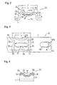
- the boot-band 10 has a band-body 11 made of a belt-shaped metal (such as stainless steel) member.
- the longitudinal ends of the band-body 11 are the first end 13, which is loose, and the second end 14.
- This band-body 11 is rolled into a ring shape around the clamped member 17 so that the first end 13 is situated on the external surface.
- One example of the clamped member 17 is a rubber boot, which is set around a cylindrical connected member 18 in a power-transmission system of an automobile.
- the band-body 11 which is curled into the shape of a ring, has an outer overlap portion 21, which is begins at the first end 13 of the band body 11, an inner overlap portion 22, which ends at the second end 14 of the band body 11, and an intermediate portion 23 (which neither overlaps nor is overlapped), which is situated between the overlap portions 21 and 22. It is preferable that the band-body 11 be previously molded into the shape of a ring.
- the ear portion 30 contains a pair of front and rear leg portions 31 and 32 that are erected on the outer circumferential surface of the band-body, and a bridge portion 33 between these leg portions 31 and 32.
- the ear portion 30 is so designed that its shape will make it possible for it to decrease the inner diameter of the band-body 11.
- curved portions (round-corner portions) 34 and 35 are formed at the opposite ends of the bridge portion 33 in the clamping direction, which are regions continuous to the tops of the leg portions 31 and 32, which curve toward the leg portions 31 and 32 in an arc shape.
- rib-like parts 36 each of which is inwardly bent by a press or the like (so-called flare working) into the ear portion 30, are formed at the opposite ends of the bridge portion 33 along a line perpendicular to the circumference. Between each pair of rib-like parts 36 is formed a dowel portion 37, which is inwardly sunk into the ear portion 30 by a press or the like.
- the rib-like parts 36 if viewed from a side of the band 10, have a convex shape like a U-shaped arc such that the inward prominence of the parts grows larger toward the middle of the bridge portion 33 in the clamping direction. Therefore, the bridge portion 33 is most rigid in its middle in the clamping direction, and the rigidity decreases toward the leg portions 31 and 32.
- the length L of the rib-like parts 36 is so designed that the ends of the rib-like parts 36 do not reach the curved portions 34 and 35.
- the bridge portion 33 is not very strong as compared with the leg portions 31 and 32. This makes it possible to prevent the leg portions 31 and 32 from damage that is caused by the stretches localized in the leg portions 31 and 32.
- the length L of the rib-like parts 36 is shorter than the length of the portion that results if the lengths (R1 + R2) of the curved portions 34 and 35 are subtracted from the length Y of the bridge portion 33 in the clamping direction.
- the length L of the rib-like parts 36 is 60% or more of that of the bridge portion 33 in the clamping direction. This secures the rigidity of the bridge portion, and reduces the maximum height of the ear portion 30 after it is plastically deformed.
- the dowel portion 37 in contrast, is formed in the middle of the bridge portion 33 on a line perpendicular to the circumference so as to extend in the clamping direction of the band-body 11, as is shown in Fig. 3 and other drawings.
- the length of the dowel portion 37 in the clamping direction is as long as, or longer than, the aforementioned length L of the rib-like parts 36.
- the transverse cross-section of the bridge portion 33 if taken along the perpendicular line to the circumference, is roughly M-shaped, as is shown in Fig. 4. It is desirable that the height of the connecting regions 39, which connect the rib-like parts 36 with the dowel portion 37, should be approximately the height of the ear portion 30 that is not subject to the plastic deformation.
- hooking holes 40 are formed along the longitudinal centerline of the band-body 11. These hooking holes 40 penetrate the strip of the band-body 11 in the thickness direction.
- a number (three, in the drawings) of hooking claws 41 are formed on the inner overlap portion 22, at locations corresponding to those of each hooking hole.
- Each of the hooking claws 41 is prominent toward the outer overlap portion 21, so that each hooking claw 41 is inserted into the corresponding hooking hole 40.
- These hooking holes 40 and hooking claws 41 are example of the fixing portions to be used in the present invention.
- the tip portion 41a of the hooking claw 41 overhangs aslant so as to be prominent toward the first end 13. Accordingly, this hooking claw 41, with its tip portion 41a being hooked over the brim portion 40a of the hooking hole 40, prevents the outer overlap portion 21 from separating from the inner overlap portion 22.
- This boot-band 10 tends to extend its winding diameter with the elastic restitution power of the band-body 11. This causes the tip portion 41a of the hooking claw 41- to hook over the brim portion 40a of the hooking hole 40, preventing the winding diameter of the band-body 11 from more extension. In this way, the boot-band 10 keeps its temporary fixation on the mating member 17, as shown in Fig. 1.
- a caulking load by the clamping jig not illustrated in the drawing (such as pincers-like tools or an automatic caulking machine), in the direction the arrow indicates in Fig. 2.
- the leg portions 31 and 32 and the curved portions 34 and 35 which are relatively less rigid than the bridge portion 33, are more subject to plastic deformation caused by this caulking load P.
- the whole ear portion is deformed plastically as illustrated in Fig. 5 and Fig. 6, that is to say, the leg portions 31 and 32 are the most subject to the plastic deformation while the curved portions 34 and 35 are only a little deformed.
- the rigidity changing of the bridge portion 33, near the curved portions 34 and 35 is relatively mild because the influence of the rigidity increase is reduced by the rib-like parts 36. This prevents the deformation from being too localized.
- the connecting regions 39, which connect the rib-like parts 36 and the dowel portion 37, are around the height of the ear portion which is not subject to plastic deformation, and the bridge portion 33 is almost flat. This particularly lowers the height of the ear portion.
- the plastic deformation of the ear portion 30 into the desired shape reduces the winding diameter or circumference of the band-body 11 and it also maintains the deformed shape of the ear portion 30 or the reduced circumference even after unloading of the caulking load. Therefore, the clamped member 17 is bonded tight on the connected member 18 by the band-body 11.
- the ear portions 30 were plastically deformed by a caulking tester 50, as shown in Fig. 7.
- the results of the 3 Embodiment Models 1, 2, and 3 are compared with those of Comparison Models 1, 2, and 3 with regard to the following evaluating criteria.
- a resin boot 53 covers the circumference of a rigid cylindrical member 52 installed inside a frame 51, and also a boot-band is attached outside the boot 53.
- the ear portion 30 is put between the acute heads of the clamping claws 54 and 55, and a caulking load P is applied to the pressure member 56 through a load-cell, which is not illustrated in the drawing. With this device, the leg portions 31 and 32 are so deformed as to contact each other and then the caulking loads are measured by the load-cell.
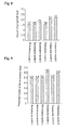
- the results of measurements of the amount of spring-back of the ear portions 30 is shown by Fig. 8.
- the measurement the purpose of which is to determine the decreases of the clamping power, is made when the clamping claws 54, and 55 of the tester 50 are removed from the caulking portion of the boot-band 10 after the plastic deformation of the ear portion 30 by the clamping claws 54 and 55.
- the maximum heights of the ear portions after their plastic deformation are shown by Fig. 9.
- the relation between the caulking load P (measurement: Newton) and the opening dimensions (the distance S between the leg portions 31 and 32) is shown by Fig. 10.
- Embodiment Models 1, 2, and 3 and Comparison Models 1, 2, and 3 shown in the graphs are all made of belt-shaped, stainless-steal (SUS304) band-bodies that are 10 mm wide and 1 mm thick. The distance between the leg portions of each model is 10 mm before the plastic deformation.
- the boot-band 10 of Embodiment Model 1 has the aforementioned rib-like parts 36 and the dowel portion 37 in the ear portion 30.
- the length L of the rib-like parts 36 is so designed as to be 60% or more of that of the bridge portion 33 in the clamping direction.
- no end of the rib-like parts 36 is designed to reach the curved portions 34 and 35.
- Embodiment Model 2 is a boot-band that also has rib-like parts 36 and a dowel portion 37, but its rib-like parts, which are longer than those of the Embodiment Model 1, reach the curved portions 34 and 35. In Embodiment Model 2, therefore, the curved portions 34 and 35 are also reinforced by the rib-like parts 36.
- Embodiment Model 3 is also a boot-band that has the aforementioned rib-like parts 36 and such a dowel portion 37, but the length L of its rib-like parts 36 is 50% of the length Y of the bridge portion 33.
- Comparison Model 1 which has an ear portion 100, as shown in Fig. 11, is a boot-band that embodies the concept of the boot-band in Japanese Utility Model Publication No. H2-9195.
- it has rib-like parts 102, each of which is outwardly prominent, formed at the opposite ends of the bridge portion 101 along a line that is perpendicular to the circumference of the ear portion 100. Between these outward rib-like parts 102 is formed a dowel portion 103 that inwardly sinks into the ear portion 100.
- Comparison model 2 shown in Fig. 12 is a boot-band that has rib-like parts 112, which are inwardly prominent into the ear portion 110, formed at the opposite ends of the bridge portion 111 along a line that is perpendicular to the circumference of the ear portion 110.
- Comparison model 3 is a boot-band that embodies the concept of the aforementioned boot-band of Japanese Patent Publication No. 2538554.
- a shallow, dish-shaped sinking 122 In the middle of the bridge portion 121 of the ear portion 120 is formed a shallow, dish-shaped sinking 122, which inwardly sinks into the ear portion, as shown in Fig. 13.
- Embodiment Models 1, 2, and 3 and Comparison Model 1 do not differ much in the amount of spring-back, which means they all are effective in maintaining the binding force.
- Comparison Models 2 and 3 show too much spring-back, which means that they remarkably lower the binding power.
- the caulking load As shown by the results, presented in Fig. 10, of the examinations of Embodiment Models 1, 2 and 3, and Comparison Models 1, 2, and 3, when the clamping is strong enough to reduce the distance between the leg portions to around 10 mm to 8 mm, the inner circumferential surface of the boot-band is brought into contact with the outer circumferential surface. Also, a greater caulking load that is enough to reduce the distance between the leg portions to 8 mm or less, compresses the boot in the thickness direction. It is noted, therefore, that the initial loading, which is to keep the distance between the leg portions at 8 mm or more, should be only such as is necessary to deform only the ear portion. Embodiment Models 1 and 2 and Comparison Model 1 show comparatively large initial loading, which means that their ear portions are highly rigid.
- Comparison Model 1 and Embodiment Model I show large caulking loads (or high rigidity of the ear portions), while Embodiment Models 2 and 3 and Comparison Models 2 and 3 show lower caulking loads.
- Comparison Models 2 and 3 and Embodiment Model 3 show lower caulking loads.
- embodiment model 2 its caulking load is lowered probably because of the thinned leg portions, which is caused by the localized plastic deformation on the leg portions and, as a result, extension of it when caulked.
- Embodiment Model 1 is especially favorable in terms of any of the criteria, which are the amount of spring-back, the maximum height of the ear portion, and the caulking loads.
- High rigidity which is obtained in Embodiment Model 1, 2 and 3, can be obtained when the length of the rib-like portion 36 is 60% or more of that of the bridge portion 33 in the clamping direction.
- the present invention when the present invention is embodied, it is possible to make necessary changes in its components, such as the shape of the ear portion, the hooking claws or holes (fixing portion), and the band-body.
- the fixing portion is, for example, need not be a combination of hooking claws and holes as in the aforementioned embodiment. It is possible to design a previously curled band-body, with its inner and outer overlap portions being connected by the fixing portion, that is to be put on the clamped member from its end side.
- the invention set forth in claim 1 it is possible to lower the prominence of the ear portion after its deformation by the clamping tool and, moreover, to reduce the amount of spring-back, by the more rigid ear portion, so as to keep the desired binding power.
- the rib-like parts which are inwardly bent into the ear portion, makes it possible to reduce the amount of assured clearance between the band and the members around it.
- the maximum height of the ear portion even with a longer bridge portion, can be lowered after its plastic deformation, because the bridge portion is kept more flat-shaped. This makes it possible to obtain a larger clamping stroke by making a longer ear portion, as well as to reduce the amount of assured clearance with the members around the band. Therefore, the rigidity distribution of the ear portion and its shape after the plastic deformation is adjustable according to the length or the shape of the rib-like parts.
Landscapes
- Engineering & Computer Science (AREA)
- General Engineering & Computer Science (AREA)
- Mechanical Engineering (AREA)
- Clamps And Clips (AREA)
- Joints That Cut Off Fluids, And Hose Joints (AREA)
Abstract
Description
- 10
- boot-band,
- 11
- band-body
- 17
- clamped member
- 21
- outer overlap portion of band-body
- 22
- inner overlap portion of band-body
- 30
- ear portion
- 31, 32
- leg portion of ear portion
- 33
- leg portion of ear portion
- 36
- rib-like part of ear portion
- 37
- dowel portion of ear portion
- 40
- hole (fixing portion)
- 41
- hooking claw (fixing portion)
Claims (4)
- A boot-band, of which belt-shaped, metal band-body, being curled in a ring, is set on a clamped member, and which is characterized in that it possesses fixing portions, which is to fix the outer overlap portion on the inner overlap portion of the aforementioned band-body, and a ear portion which, having a pair of leg portions, outwardly prominent, and a bridge portion connecting these leg portions, is formed in a region of the aforementioned band-body in the circumferential direction and can be plastically deformed to reduce the circumference of the band-body, and that in the ear portion are formed rib-like parts, each inwardly bent into the leg portion, at the opposite ends of the aforementioned bridge portion on the perpendicular line to the circumference and between the aforementioned rib-like portions are formed a dowel portion, inwardly sinking into the ear portion.
- A boot-band as set forth in claim 1, characterized in that the aforementioned rib-like parts are so arc-shaped that the prominence, inwardly bulging into the ear portion, grows larger toward the middle of the aforementioned bridge portion in the clamping direction.
- A boot-band as set forth in claim 2, characterized in that the aforementioned rib-like parts are not long enough to reach the curved portions at the opposite ends of the aforementioned bridge portion in the clamping direction.
- A boot-band as set forth in claim 3, characterized in that the length of the aforementioned rib-like parts is 60% and more of that of the bridge portion in the clamping direction..
Applications Claiming Priority (3)
| Application Number | Priority Date | Filing Date | Title |
|---|---|---|---|
| JP13480399 | 1999-05-14 | ||
| JP13480399 | 1999-05-14 | ||
| PCT/JP2000/003072 WO2000070260A1 (en) | 1999-05-14 | 2000-05-12 | Boot band |
Publications (3)
| Publication Number | Publication Date |
|---|---|
| EP1193437A1 true EP1193437A1 (en) | 2002-04-03 |
| EP1193437A4 EP1193437A4 (en) | 2003-05-28 |
| EP1193437B1 EP1193437B1 (en) | 2009-12-16 |
Family
ID=15136904
Family Applications (1)
| Application Number | Title | Priority Date | Filing Date |
|---|---|---|---|
| EP00925655A Expired - Lifetime EP1193437B1 (en) | 1999-05-14 | 2000-05-12 | Clamp band |
Country Status (6)
| Country | Link |
|---|---|
| US (1) | US6560824B1 (en) |
| EP (1) | EP1193437B1 (en) |
| JP (1) | JP3965488B2 (en) |
| CN (1) | CN1167893C (en) |
| AU (1) | AU4433000A (en) |
| WO (1) | WO2000070260A1 (en) |
Cited By (1)
| Publication number | Priority date | Publication date | Assignee | Title |
|---|---|---|---|---|
| WO2003081111A1 (en) * | 2002-03-19 | 2003-10-02 | Mikalor S.A. | Improvements to bridges for flat band clamps |
Families Citing this family (9)
| Publication number | Priority date | Publication date | Assignee | Title |
|---|---|---|---|---|
| JP4499880B2 (en) * | 2000-07-05 | 2010-07-07 | 日本発條株式会社 | Boots band |
| JP4045537B2 (en) * | 2002-06-06 | 2008-02-13 | 日本発条株式会社 | Boots band |
| JP4505713B2 (en) * | 2003-08-19 | 2010-07-21 | 日本発條株式会社 | Boots band |
| US7134696B2 (en) * | 2004-01-23 | 2006-11-14 | Trans-Matic Mfg. Co., Incorporated | Compression cap |
| JP4729688B2 (en) * | 2004-09-30 | 2011-07-20 | 日本発條株式会社 | Endless boot fixing band and manufacturing method thereof |
| CN102066821B (en) * | 2008-06-18 | 2016-07-06 | 汉斯奥蒂克机械和设备工厂股份公司 | Hose clip |
| MX2016002069A (en) * | 2013-08-20 | 2016-08-17 | Oetiker Schweiz Ag | Hose clamp. |
| US9834352B2 (en) * | 2014-11-24 | 2017-12-05 | Thomas & Betts International Llc | Non-slip cable tie |
| CN106764086A (en) * | 2016-12-23 | 2017-05-31 | 慈溪铭展工贸有限公司 | A kind of pipe clamp |
Family Cites Families (9)
| Publication number | Priority date | Publication date | Assignee | Title |
|---|---|---|---|---|
| US4222155A (en) * | 1978-11-01 | 1980-09-16 | Hans Oetiker | Hose clamp |
| US4299012A (en) | 1979-05-08 | 1981-11-10 | Hans Oetiker | Hose clamp |
| US4430775A (en) * | 1981-12-14 | 1984-02-14 | Arvin Industries, Inc. | Muffler shield banding strap |
| JPS60138089A (en) | 1983-12-26 | 1985-07-22 | Kawasaki Steel Corp | Production of steel sheet subjected to surface treatment on one side |
| JPS60138089U (en) * | 1984-02-27 | 1985-09-12 | エヌエス工業株式会社 | hose band |
| US5564167A (en) * | 1984-06-20 | 1996-10-15 | Hans Oetiker Ag Maschinen -Und Apparatefabrik | Reinforced ear structure for clamps |
| US4756060A (en) * | 1985-11-18 | 1988-07-12 | Nhk Spring Co., Ltd. | Hose band |
| JPS63172085A (en) | 1987-01-09 | 1988-07-15 | 日本発条株式会社 | Hose band |
| US5537721A (en) * | 1994-08-19 | 1996-07-23 | Hans Oetiker Ag Maschinen- Und Apparatefabrik | Tolerance-compensating hose clamp |
-
2000
- 2000-05-12 CN CNB008082022A patent/CN1167893C/en not_active Expired - Fee Related
- 2000-05-12 JP JP2000618650A patent/JP3965488B2/en not_active Expired - Fee Related
- 2000-05-12 EP EP00925655A patent/EP1193437B1/en not_active Expired - Lifetime
- 2000-05-12 AU AU44330/00A patent/AU4433000A/en not_active Abandoned
- 2000-05-12 WO PCT/JP2000/003072 patent/WO2000070260A1/en not_active Ceased
- 2000-05-12 US US09/959,900 patent/US6560824B1/en not_active Expired - Lifetime
Cited By (2)
| Publication number | Priority date | Publication date | Assignee | Title |
|---|---|---|---|---|
| WO2003081111A1 (en) * | 2002-03-19 | 2003-10-02 | Mikalor S.A. | Improvements to bridges for flat band clamps |
| ES2223220A1 (en) * | 2002-03-19 | 2005-02-16 | Mikalor, S.A. | Improvements to bridges for flat band clamps |
Also Published As
| Publication number | Publication date |
|---|---|
| EP1193437A4 (en) | 2003-05-28 |
| US6560824B1 (en) | 2003-05-13 |
| CN1359458A (en) | 2002-07-17 |
| AU4433000A (en) | 2000-12-05 |
| JP3965488B2 (en) | 2007-08-29 |
| CN1167893C (en) | 2004-09-22 |
| EP1193437B1 (en) | 2009-12-16 |
| WO2000070260A1 (en) | 2000-11-23 |
Similar Documents
| Publication | Publication Date | Title |
|---|---|---|
| US6560824B1 (en) | Boot-band | |
| JPS586109B2 (en) | hose clamp | |
| JP3678805B2 (en) | Tolerance compensation hose clamp | |
| CA2135219C (en) | Earless, stepless clamp structure | |
| JPWO2000070260A1 (en) | Boot band | |
| JPH0587280A (en) | Clamp structure with improved spring action | |
| JP4045537B2 (en) | Boots band | |
| US6860527B2 (en) | Strap clamp | |
| SK102095A3 (en) | Jack and method of fastening of its compensation | |
| MXPA04011157A (en) | Open hose clamp with plastically deformable ear and method of making the same. | |
| JPS61140688A (en) | Brake hose with intermediate joint fitting | |
| KR100625140B1 (en) | Fastening means for hose clamps | |
| EP0710780B1 (en) | Installation ring for mounting pressurized fluid buffer device and fabrication method therefor | |
| JP3927690B2 (en) | Boots band | |
| JP3853955B2 (en) | Boots band | |
| US20250369462A1 (en) | Clamp with stronger closing hook design | |
| JP3556620B2 (en) | Hydraulic hose connection fitting fastening structure | |
| US11460132B2 (en) | Locator systems and methods for hose clamps | |
| JPS63172085A (en) | Hose band | |
| KR20260001686A (en) | A method of manufacturing a Tooth Lock Band for Boot Fastening of a Constant Speed Joint with Improved Fixing Power | |
| JP3049050U (en) | Flexible pipe | |
| FI95833C (en) | Collar, especially tension collar | |
| JPH0126949Y2 (en) | ||
| JPH10217728A (en) | Tightening rope fixing metal fitting for tire-skid preventing device | |
| JPH10252967A (en) | Pipe fittings and hoses with pipe fittings |
Legal Events
| Date | Code | Title | Description |
|---|---|---|---|
| PUAI | Public reference made under article 153(3) epc to a published international application that has entered the european phase |
Free format text: ORIGINAL CODE: 0009012 |
|
| 17P | Request for examination filed |
Effective date: 20011213 |
|
| AK | Designated contracting states |
Kind code of ref document: A1 Designated state(s): AT BE CH CY DE DK ES FI FR GB GR IE IT LI LU MC NL PT SE |
|
| AX | Request for extension of the european patent |
Free format text: AL;LT;LV;MK;RO;SI |
|
| A4 | Supplementary search report drawn up and despatched |
Effective date: 20030415 |
|
| REG | Reference to a national code |
Ref country code: DE Ref legal event code: 8566 |
|
| RBV | Designated contracting states (corrected) |
Designated state(s): FR GB |
|
| 17Q | First examination report despatched |
Effective date: 20050513 |
|
| GRAP | Despatch of communication of intention to grant a patent |
Free format text: ORIGINAL CODE: EPIDOSNIGR1 |
|
| RTI1 | Title (correction) |
Free format text: CLAMP BAND |
|
| GRAS | Grant fee paid |
Free format text: ORIGINAL CODE: EPIDOSNIGR3 |
|
| GRAA | (expected) grant |
Free format text: ORIGINAL CODE: 0009210 |
|
| AK | Designated contracting states |
Kind code of ref document: B1 Designated state(s): FR GB |
|
| REG | Reference to a national code |
Ref country code: GB Ref legal event code: FG4D |
|
| PLBE | No opposition filed within time limit |
Free format text: ORIGINAL CODE: 0009261 |
|
| STAA | Information on the status of an ep patent application or granted ep patent |
Free format text: STATUS: NO OPPOSITION FILED WITHIN TIME LIMIT |
|
| 26N | No opposition filed |
Effective date: 20100917 |
|
| REG | Reference to a national code |
Ref country code: FR Ref legal event code: PLFP Year of fee payment: 17 |
|
| REG | Reference to a national code |
Ref country code: FR Ref legal event code: PLFP Year of fee payment: 18 |
|
| REG | Reference to a national code |
Ref country code: FR Ref legal event code: PLFP Year of fee payment: 19 |
|
| PGFP | Annual fee paid to national office [announced via postgrant information from national office to epo] |
Ref country code: GB Payment date: 20180329 Year of fee payment: 19 |
|
| PGFP | Annual fee paid to national office [announced via postgrant information from national office to epo] |
Ref country code: FR Payment date: 20180412 Year of fee payment: 19 |
|
| GBPC | Gb: european patent ceased through non-payment of renewal fee |
Effective date: 20190512 |
|
| PG25 | Lapsed in a contracting state [announced via postgrant information from national office to epo] |
Ref country code: GB Free format text: LAPSE BECAUSE OF NON-PAYMENT OF DUE FEES Effective date: 20190512 |
|
| PG25 | Lapsed in a contracting state [announced via postgrant information from national office to epo] |
Ref country code: FR Free format text: LAPSE BECAUSE OF NON-PAYMENT OF DUE FEES Effective date: 20190531 |