EP1193429A1 - Shaft sealing mechanism of compressor by mechanical seal - Google Patents
Shaft sealing mechanism of compressor by mechanical seal Download PDFInfo
- Publication number
- EP1193429A1 EP1193429A1 EP01926126A EP01926126A EP1193429A1 EP 1193429 A1 EP1193429 A1 EP 1193429A1 EP 01926126 A EP01926126 A EP 01926126A EP 01926126 A EP01926126 A EP 01926126A EP 1193429 A1 EP1193429 A1 EP 1193429A1
- Authority
- EP
- European Patent Office
- Prior art keywords
- sliding ring
- rotary
- sliding
- ring
- side sliding
- Prior art date
- Legal status (The legal status is an assumption and is not a legal conclusion. Google has not performed a legal analysis and makes no representation as to the accuracy of the status listed.)
- Withdrawn
Links
Images

Classifications
-
- F—MECHANICAL ENGINEERING; LIGHTING; HEATING; WEAPONS; BLASTING
- F16—ENGINEERING ELEMENTS AND UNITS; GENERAL MEASURES FOR PRODUCING AND MAINTAINING EFFECTIVE FUNCTIONING OF MACHINES OR INSTALLATIONS; THERMAL INSULATION IN GENERAL
- F16J—PISTONS; CYLINDERS; SEALINGS
- F16J15/00—Sealings
- F16J15/16—Sealings between relatively-moving surfaces
- F16J15/34—Sealings between relatively-moving surfaces with slip-ring pressed against a more or less radial face on one member
- F16J15/3464—Mounting of the seal
- F16J15/3472—Means for centering or aligning the contacting faces
Definitions
- the present invention relates to a technique for shaft-sealing a circumference of a rotary shaft of a compressor of an air-conditioner using a mechanical seal.
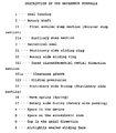
- Fig. 6 is a view showing a typical example of a conventional mechanical seal used as a shaft-seal means of a compressor of an air-conditioner for automobile use (a car air-conditioner) in which CO 2 gas is used as refrigerant.
- This type mechanical seal 200 is composed as follows. On the rotary shaft 101 of a gas compressor, the refrigerant of which is CO 2 gas, the rotary side sliding ring 201 is arranged via the O-ring 202 in such a manner that the rotary side sliding ring 201 is capable of moving in the axial direction and rotating together with the rotary shaft 101.
- the stationary side sliding ring 203 which cannot rotate, is airtightly arranged via the O-ring 204 on the seal housing 102 side of the gas compressor, the refrigerant of which is CO 2 gas.
- the rotary side sliding ring 201 is closely contacted with the stationary side sliding ring 203 by a pushing force generated by the spring 205 in the axial direction.
- both the rings 201 and 203 are closely contacted with each other, the airtightly sealed sliding face 200S is formed.
- space A in the device which is located on the right in the drawing and reaches the outer circumference of the airtightly sealed sliding face 200S, is filled with an atmosphere of CO 2 gas containing refrigerating machine oil.
- Space B on the atmosphere side reaches the inner circumference of the airtightly sealed sliding face 200S.
- the differential pressure ⁇ p between space A in the device and space B on the atmosphere side changes in a range from 3 to 13 MPa.
- the rotary side sliding ring 201 is made of carbon sliding material having a self-lubrication property.
- the sliding protrusion 201a which is continuously formed in the circumferential direction, of the rotary side sliding ring 201 is slidably contacted with the stationary side sliding ring 203.
- the stationary side sliding ring 203 is made of sliding material of ceramics which is harder than the carbon sliding material described above.
- the rotary side sliding ring 201 made of carbon sliding material, the Young's modulus of which is low, is deformed into a tapered-shape which is exaggeratedly shown in Fig. 7.
- the reason why the rotary side sliding ring 201 is deformed into a tapered-shape will be explained as follows.
- the rotary side sliding ring 201 is given a displacement force as shown by arrow "f" by the differential pressure ⁇ p acting in the radial direction on a portion close to the stationary side sliding ring 203 with respect to the O-ring 202 which is arranged on an inner circumference of the rotary side sliding ring 201.
- the sliding protrusion 201a the bending strength of which is low from the viewpoints of profile and structure, further leans against the inner circumferential side by the differential pressure acting in the radial direction.
- the outer diameter of the sliding protrusion 201a is approximately 20 mm and the width of the airtightly sealed sliding face 200S in the radial direction is approximately 2 mm, partial abrasion is caused by sliding in which the quantity of abrasion in the outer circumferential portion of the sliding protrusion 201a is larger than that in the inner circumferential portion of the sliding protrusion 201a by about 1 to 3 fm (femto-meter).
- the present invention has been accomplished to solve the above problems.
- the primary technical task of the present invention is to prevent the collapse of an oil film on the airtightly sealed sliding face and suppress the leakage of refrigerant gas caused by the collapse of the oil film when deformation of the sliding ring and sliding protrusion caused by the pressure in the space in the device is reduced and partial abrasion on the airtightly sealed sliding face, which is caused by the deformation, is reduced.
- the present invention provides a shaft seal mechanism of a compressor with a mechanical seal, the mechanical seal comprising: a rotary side sliding ring supported by an outer circumferential face on a large diameter side of an annular step section formed on a rotary shaft of a compressor via a rotary side packing, the rotary side sliding ring being press-fitted into the annular step section by gas pressure in the device; and a stationary side sliding ring, which is not rotated, airtightly fixed onto a seal housing side of the compressor via a stationary side packing in such a manner that the stationary side sliding ring can be moved in the axial direction, the stationary side sliding ring airtightly coming into contact with the rotary side sliding ring by a pushing force of a spring in the axial direction so as to form an airtightly sealed sliding face, wherein a space in the device in which gas to be sealed exists reaches an outer circumferential side of the airtightly sealed sliding face, the rotary side sliding ring is made of a self-lubrication sliding material,
- the rotary side sliding ring is given a deforming force in the leaning direction by a differential pressure between high gas pressure in the device and atmospheric pressure outside the device, however, this deforming force is canceled by a deforming force generated by a component force in the axial direction of the differential pressure acting on the annular step section of the rotary shaft in a pushing direction. Therefore, the occurrence of partial abrasion of the airtightly sealed sliding face, which is caused by a deformation of the rotary side sliding ring by leaning, can be suppressed.
- the stationary side sliding ring is also given a deforming force in the leaning direction by the differential pressure in the same manner as that described above. However, since this stationary side sliding ring is made of material, the Young's modulus of which is high, a quantity of deformation is very low, which causes no problems.
- a gap in the axial direction is formed in an outer circumferential section between an annular step section of the rotary shaft and a back face of an inner diameter section of the rotary side sliding ring, which are contacted with each other, being located on the inner diameter side with respect to an airtightly sealed section formed by the rotary side packing. Due to the foregoing, a deforming force, the direction of which is opposite to that of the deformation of the rotary side sliding ring by leaning, is generated. Therefore, the occurrence of partial abrasion on the outer circumferential side of the airtightly sealed sliding face caused by the deformation by leaning can be more positively prevented.
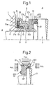
- Fig. 1 is a view showing a preferable embodiment of a shaft seal mechanism of a compressor with a mechanical seal of the present invention.
- reference numeral 1 is a seal housing of a compressor of an air-conditioner for automobile use in which CO 2 is used as refrigerant.
- Reference numeral 2 is a rotary shaft which is inserted from an inner circumference of the shaft hole 11 of this seal housing 1 into the compressor and rotated when a drive force is given to it from a crank shaft of an engine via an electromagnetic clutch (not shown) so that the inner mechanism of the compressor can be driven.
- the mechanical seal 3 is arranged between the seal housing 1 and the rotary shaft 2.
- the stationary side sliding ring 31, which is attached to the seal housing 1 side in an unturnable state, and the rotary side sliding ring 32, which is attached to the rotary shaft 2 side and rotated integrally with this rotary shaft 2, are opposed to each other in the axial direction.
- the mechanical seal 3 exhibits a shaft seal function on the airtightly-sealed sliding face S on which end faces of the stationary side sliding ring 31 and the rotary side sliding ring 32 come closely into contact with each other.
- Spaces are formed around the shaft on both sides of the mechanical seal 3 in the axial direction.
- Space A which exists on the right of the seal housing 1 and reaches the outer circumference of the airtightly sealed sliding face S in Fig. 1, is a space in the device to be sealed
- space B which exists on the left of the seal housing 1 and reaches the inner circumference of the airtightly sealed sliding face S in Fig. 1, is an atmospheric side space open to the outside of the device.
- the structure of the mechanical seal 3 will be explained in more detail as follows.
- the rotary side sliding ring 32 is made of carbon sliding material and arranged on the side of space A in the device when the rotary side sliding ring 32 is viewed from the stationary side sliding ring 31.
- This rotary side sliding ring 32 is fixed onto the outer circumferential face of the rotary shaft 2 via the O-ring 37.
- the rotary shaft 2 has an annular step section 21, 22 at a position where the rotary side sliding ring 32 is attached, and the diameter of the inserting section of this annular step section 21, 22, into the shaft hole 11 of the seal housing 1, is small.
- the rotary side sliding ring 32 includes; an inner circumference radial direction section 321, the back face of which comes into contact with the first annular step section 21 on the small diameter side; and an outer circumference axial direction section 322 which extends from the outer circumferential end section to the back face side and is held by the large diameter side outer circumferential face 23 of the first annular step section 21 via the O-ring 37.
- the stationary side sliding ring 31 is made of hard sliding material (for example, a ceramic such as SiC), the Young's modulus of which is higher than that of the carbon sliding material.
- the stationary side sliding ring 31 is attached via the stationary side O-ring 33 in such a manner that the stationary side sliding ring 31 can be freely moved in the axial direction.
- the stationary side O-ring 33 when this stationary side O-ring 33 is accommodated in the packing accommodating recess 31a formed on the inner circumferential face on the back face of the stationary side sliding ring 31, the stationary side O-ring 33 is given an appropriate squeeze in the radial direction between the outer circumferential face of the cylindrical support section 12 and the stationary side sliding ring 31.
- the retainer 34 composed of a metal sheet is arranged, and the inner diameter section of the retainer 34 extends in such a manner that the rear of the packing accommodating recess 31a of the stationary side sliding ring 31 is closed.
- a case 35 composed of a flange-shaped metal sheet.
- This case 35 is engaged in the circumferential direction with the engaging section 12a formed on the outer circumferential face of the base portion of the cylindrical support section 12.
- this case 35 is engaged in the axial direction with the end face 13 of the seal housing 1 rising from the rear end of the base portion.
- a wave spring 36 which is appropriately compressed in the axial direction.
- a plurality of engagement pawls 35a extending in the axial direction are arranged at regular intervals.
- engagement pawls 35a are engaged with the engagement notches 31b formed on the outer circumferential face of the stationary side sliding ring 31 at the same phase intervals in such a manner that the engagement pawls 35a can be freely relatively moved in the axial direction.
- the stationary side sliding ring 31 is attached to the seal housing 1 in such a manner that the stationary side sliding ring 31 cannot be rotated with respect to the seal housing 1 by the engaging section 12a of the cylindrical support section 12 and the case 35.
- a pushing force of the wave spring 36, in the axial direction, is given to the stationary side sliding ring 31 via the retainer 34. Therefore, the forward end face 31c of the stationary side sliding ring 31 is pressed against a forward end face of the sliding protrusion 323 of the rotary side sliding ring 32, which is rotated together with the rotary shaft 2, with an appropriate surface pressure, and an airtightly sealed sliding face S is formed.
- refrigerating machine oil is mixed as a mist with refrigerant CO 2 gas, which is compressed by the compressor at high pressure and temperature.
- a portion of the refrigerating machine oil mixed with the refrigerant CO 2 gas is introduced onto the airtightly sealed sliding face S and formed into a lubricant film, which excellently lubricates the airtightly sealed sliding face S and shuts off the refrigerant CO 2 gas so that it cannot leak to space B on the atmospheric side.
- the pressure of the refrigerant CO 2 gas in space A in the device is higher than the atmospheric pressure in space B on the atmospheric side. Therefore, differential pressure between the atmospheric pressure and the pressure of the refrigerant CO 2 gas acting on the back face of the stationary side sliding ring 31 on the outer circumferential side of the airtightly sealed section by the stationary side O-ring 33, acts as a pressing load which increases surface pressure on the airtightly sealed sliding face S.
- the sliding protrusion 323, which forms the airtightly sealed sliding face S together with the stationary side sliding ring 31, is protruded from the inner circumferential radial direction section 321 and located on the inner diameter side with respect to the airtightly sealed section by the rotary side O-ring 37. Therefore, as shown in Fig.
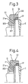
- a pressure receiving area of differential pressure ⁇ p 1 acting on the front face of the rotary side sliding ring 32 in the axial direction on the outer circumferential side of the airtightly sealed sliding face S is larger than a pressure receiving area of differential pressure ⁇ p 2 acting on the back face of the rotary side sliding ring 32 in the axial direction on the outer circumferential side of the section airtightly sealed by the rotary side O-ring 37. Accordingly, by the axial direction load F 1 , caused by the difference between the pressure receiving areas, in this rotary side sliding ring 32, the back face of the inner circumferential radial direction section 321 is fixed being press-fitted to the first annular step section 21 of the rotary shaft 2.
- differential pressure ⁇ p 3 acting on the rotary side sliding ring 32 in the radial direction generates a deforming force F 2 by which the rotary side sliding ring 32 is made to lean against the stationary side sliding ring 31 side as shown by the two-dotted chain line in Fig. 2.
- the load F 1 in the axial direction described above acts in a direction so that the above deforming force F 2 can be canceled. Therefore, it is possible to prevent the rotary side sliding ring 32 from leaning in the direction of F 2 . Due to the foregoing, it is possible to effectively prevent the occurrence of partial abrasion in which a quantity of abrasion on the airtightly sealed sliding face S (sliding protrusion 323) is increased on the outer circumferential side.
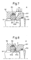
- Fig. 3 is a view showing the second embodiment of the present invention.
- the auxiliary step section 21a in the first annular step section 21 on the rotary shaft 2, the auxiliary step section 21a, the outer diameter of which corresponds to the sliding protrusion 323 of the rotary side sliding ring 32, is formed.
- the axial direction gap G which is located on the inner diameter side with respect to the airtightly sealed section by the rotary side O-ring 37, is formed.
- the structure of other portions is substantially the same as that shown in Fig. 1.
- the inner diameter (outer diameter of the auxiliary step section 21a) of the gap G in the axial direction is set according to a state of use so that the airtightly sealed sliding face S can be put into an appropriate contact condition.
- Fig. 5 is a view showing the third embodiment of the present invention.
- the clearance groove 321a is formed which is continuous in the circumferential direction. Due to the foregoing, in the outer circumferential section between the inner circumferential radial direction section 321 and the first annular step section 21 of the rotary shaft 2, the gap G, which is located on the inner diameter side with respect to the airtightly sealed section by the rotary side O-ring 37, is formed.
- the structure of other portions is substantially the same as that shown in Fig. 1.
- the rotary side sliding ring 32 is made of carbon sliding material, however, it is possible to use another self-lubrication sliding material such as PTFE or polyimide.
- the shaft sealing mechanism of the compressor by the mechanical seal of the present invention even if the refrigerant gas pressure in the device is increased to be high, it is possible to prevent the occurrence of partial abrasion on the outer circumferential side of the airtightly sealed sliding face caused by deformation when the rotary side sliding ring leans. Also, it is possible to prevent an increase in the sliding load caused by partial abrasion. Further, it is possible to effectively suppress an increase in the leakage of refrigerant gas.
Landscapes
- Engineering & Computer Science (AREA)
- General Engineering & Computer Science (AREA)
- Mechanical Engineering (AREA)
- Mechanical Sealing (AREA)
- Compressor (AREA)
Abstract
Description
Claims (3)
- A shaft seal mechanism of a compressor with a mechanical seal, the mechanical seal comprising:a rotary side sliding ring supported by an outer circumferential face on a large diameter side of an annular step section formed on a rotary shaft of a compressor via a rotary side packing, the rotary side sliding ring being press-fitted into the annular step section by gas pressure in the device; anda stationary side sliding ring, which is not rotated, airtightly fixed onto a seal housing side of the compressor via a stationary side packing in such a manner that the stationary side sliding ring can be moved in the axial direction, the stationary side sliding ring airtightly coming into contact with the rotary side sliding ring by a pushing force of a spring in the axial direction so as to form an airtightly sealed sliding face, whereina space in the device, in which gas to be sealed exists, reaches an outer circumferential side of the airtightly sealed sliding face,the rotary side sliding ring is made of a self-lubrication sliding material,the stationary side sliding ring is made of a sliding material, the Young's modulus of which is higher than that of the self-lubrication sliding material, anda sliding protrusion extending from the rotary side sliding ring in the circumferential direction slidably comes into contact with the stationary side sliding ring.
- A shaft seal mechanism of a compressor with a mechanical seal according to claim 1, wherein the self-lubrication sliding material is a carbon sliding material, a PTFE sliding material or a polyimide sliding material.
- A shaft seal mechanism of a compressor by a mechanical seal according to claim 1, wherein a gap in the axial direction is formed in an outer circumferential section between an annular step section of the rotary shaft and a back face of an inner diameter section of the rotary side sliding ring, which are contacted with each other, being located on the inner diameter side with respect to an airtightly sealed section formed by the rotary side packing.
Applications Claiming Priority (3)
| Application Number | Priority Date | Filing Date | Title |
|---|---|---|---|
| JP2000133235 | 2000-05-02 | ||
| JP2000133235A JP4606545B2 (en) | 2000-05-02 | 2000-05-02 | Compressor shaft seal mechanism with mechanical seal |
| PCT/JP2001/003811 WO2001084025A1 (en) | 2000-05-02 | 2001-05-02 | Shaft sealing mechanism of compressor by mechanical seal |
Publications (2)
| Publication Number | Publication Date |
|---|---|
| EP1193429A1 true EP1193429A1 (en) | 2002-04-03 |
| EP1193429A4 EP1193429A4 (en) | 2006-01-18 |
Family
ID=18641767
Family Applications (1)
| Application Number | Title | Priority Date | Filing Date |
|---|---|---|---|
| EP01926126A Withdrawn EP1193429A4 (en) | 2000-05-02 | 2001-05-02 | Shaft sealing mechanism of compressor by mechanical seal |
Country Status (4)
| Country | Link |
|---|---|
| US (1) | US6688602B2 (en) |
| EP (1) | EP1193429A4 (en) |
| JP (1) | JP4606545B2 (en) |
| WO (1) | WO2001084025A1 (en) |
Families Citing this family (10)
| Publication number | Priority date | Publication date | Assignee | Title |
|---|---|---|---|---|
| US7389832B2 (en) * | 2006-05-26 | 2008-06-24 | Dyna-Drill Technologies, Inc. | Hydrostatic mechanical seal with local pressurization of seal interface |
| CA2746726C (en) * | 2008-12-12 | 2015-03-10 | Flowserve Management Company | Pump seal |
| GB0908201D0 (en) * | 2009-05-13 | 2009-06-24 | Crane John Uk Ltd | Seal assemblies |
| DE102010024289A1 (en) * | 2010-04-23 | 2011-10-27 | Carl Freudenberg Kg | Mechanical seal |
| ITVI20120048A1 (en) * | 2012-02-29 | 2013-08-30 | Calpeda A Spa | SEALING GROUP FOR A FLUID |
| US9261095B2 (en) * | 2012-08-31 | 2016-02-16 | Cornell Pump Company | Cutter system for pump suction |
| US9845697B2 (en) * | 2015-01-19 | 2017-12-19 | United Technologies Corporation | Sliding seal |
| US10260364B2 (en) | 2015-03-09 | 2019-04-16 | United Technologies Corporation | Sliding seal |
| WO2019059197A1 (en) * | 2017-09-20 | 2019-03-28 | イーグル工業株式会社 | Mecanical seal |
| CN109932169B (en) * | 2019-04-08 | 2020-05-29 | 浙江大学 | A mechanical seal test device with adjustable axis declination angle of seal ring |
Family Cites Families (26)
| Publication number | Priority date | Publication date | Assignee | Title |
|---|---|---|---|---|
| US3511510A (en) * | 1964-05-25 | 1970-05-12 | Sealol | High pressure fluid seal with biasing action |
| CA919210A (en) * | 1968-12-30 | 1973-01-16 | Westinghouse Electric Corporation | Controlled leakage face type shaft seal |
| DE2315190B2 (en) * | 1973-03-27 | 1978-04-20 | Klein, Schanzlin & Becker Ag, 6710 Frankenthal | Hydrostatic mechanical seal |
| GB2080446B (en) * | 1980-07-17 | 1984-08-15 | Fenner Co Ltd J H | Annular fluid seals |
| JPS60178661A (en) | 1984-02-24 | 1985-09-12 | Nec Corp | Manufacture of semiconductor device |
| JPS60178661U (en) * | 1984-05-10 | 1985-11-27 | イ−グル工業株式会社 | mechanical seal |
| JPS6237665A (en) | 1985-08-09 | 1987-02-18 | 三洋電機株式会社 | Refrigerated counter |
| JPS6237573A (en) | 1985-08-12 | 1987-02-18 | Ebara Res Co Ltd | Shaft seal device |
| FI74121C (en) | 1986-01-22 | 1988-08-01 | Safematic Ltd Oy | Mechanical seals |
| US4691927A (en) * | 1986-12-01 | 1987-09-08 | A. W. Chesterton Company | Temperature-compensating mechanical face seal |
| US4848774A (en) * | 1987-08-31 | 1989-07-18 | Westinghouse Electric Corp. | Reactor coolant pump hydrostatic sealing assembly with externally pressurized hydraulic balance chamber |
| FI882106A7 (en) | 1988-05-05 | 1989-11-06 | Safematic Ltd Oy | ANORDNING FOER AENDTAETNING VID EN BOEJNINGSKOMPENSERAD ELLER -REGLERAD VALS. |
| JPH0544618Y2 (en) * | 1988-05-30 | 1993-11-12 | ||
| JPH0614159Y2 (en) * | 1989-02-23 | 1994-04-13 | イーグル工業株式会社 | mechanical seal |
| ATE106999T1 (en) * | 1989-12-06 | 1994-06-15 | Pacific Wietz Gmbh & Co Kg | GAS BARRIER, NON-CONTACT SEAL ASSEMBLY FOR SINGLE SHAFT. |
| JPH04125364A (en) | 1990-09-18 | 1992-04-24 | Riken Corp | Shaft seal device for stirling cycle |
| JP2744856B2 (en) | 1991-05-22 | 1998-04-28 | 工業技術院長 | Titanium boride composite silicon carbide sintered body for mechanical seal and mechanical seal |
| JPH0540661A (en) | 1991-08-02 | 1993-02-19 | Nec Corp | Simulator |
| JP2558860Y2 (en) * | 1991-10-29 | 1998-01-14 | 株式会社タンケンシールセーコウ | mechanical seal |
| US5567132A (en) * | 1994-12-06 | 1996-10-22 | Endura Pumps International, Inc. | Seal for pump having an internal gas pump |
| CH689826A5 (en) | 1995-05-10 | 1999-12-15 | Daimler Benz Ag | Vehicle air conditioner. |
| JP4008098B2 (en) | 1998-04-10 | 2007-11-14 | イーグル工業株式会社 | Shaft seal structure of refrigerator compressor |
| JP4307590B2 (en) | 1998-05-29 | 2009-08-05 | イーグル工業株式会社 | Shaft seal device for refrigerator compressor |
| US6227547B1 (en) | 1998-06-05 | 2001-05-08 | Kalsi Engineering, Inc. | High pressure rotary shaft sealing mechanism |
| JP3280344B2 (en) * | 1999-05-14 | 2002-05-13 | 日本ピラー工業株式会社 | mechanical seal |
| JP3351515B2 (en) | 1999-09-01 | 2002-11-25 | 日本ピラー工業株式会社 | mechanical seal |
-
2000
- 2000-05-02 JP JP2000133235A patent/JP4606545B2/en not_active Expired - Lifetime
-
2001
- 2001-05-02 EP EP01926126A patent/EP1193429A4/en not_active Withdrawn
- 2001-05-02 US US10/019,844 patent/US6688602B2/en not_active Expired - Fee Related
- 2001-05-02 WO PCT/JP2001/003811 patent/WO2001084025A1/en not_active Ceased
Also Published As
| Publication number | Publication date |
|---|---|
| EP1193429A4 (en) | 2006-01-18 |
| US6688602B2 (en) | 2004-02-10 |
| US20030098547A1 (en) | 2003-05-29 |
| JP4606545B2 (en) | 2011-01-05 |
| JP2001317637A (en) | 2001-11-16 |
| WO2001084025A1 (en) | 2001-11-08 |
Similar Documents
| Publication | Publication Date | Title |
|---|---|---|
| EP0942209B1 (en) | Rotary cartridge seals with retainer | |
| US4755115A (en) | Shaft seal assembly for compressor | |
| EP0835398B1 (en) | Skew and twist resistant hydrodynamic rotary shaft seal | |
| US20100295253A1 (en) | Packing and sealing system | |
| JPWO2002099320A1 (en) | Sealing device | |
| US6688602B2 (en) | Shaft sealing mechanism of compressor with mechanical seal | |
| US7828300B2 (en) | Sealing device for reciprocating shaft | |
| JP2009074602A (en) | Oil seal | |
| CN102549320A (en) | Seal device | |
| US8651496B2 (en) | Seal | |
| EP1098117A1 (en) | Mechanical seal for compressor | |
| US11221074B2 (en) | Mechanical seal | |
| US6158744A (en) | Seal arrangement providing a seal between a bore and a rod movable in the bore | |
| EP1164317A2 (en) | Sealing structure for joint of housing parts | |
| WO2020112558A1 (en) | Seal assembly with anti-rotation and stability features | |
| CN110520658B (en) | Configuration of seals | |
| US7534101B2 (en) | Pump with radial packing ring | |
| EP3315833A1 (en) | Shaft seal device of refrigerator compressor | |
| EP3742027A1 (en) | Seal structure and seal to be used in same | |
| JP2005240932A (en) | Sealing device | |
| JP5087284B2 (en) | Shaft seal device | |
| KR20230145489A (en) | Sealing structure and sealing method | |
| JP2006177500A (en) | Mechanical seal | |
| JP2000055207A (en) | Sealing device | |
| US11592108B2 (en) | Seal having a lip optimized for low temperature applications |
Legal Events
| Date | Code | Title | Description |
|---|---|---|---|
| PUAI | Public reference made under article 153(3) epc to a published international application that has entered the european phase |
Free format text: ORIGINAL CODE: 0009012 |
|
| 17P | Request for examination filed |
Effective date: 20011228 |
|
| AK | Designated contracting states |
Kind code of ref document: A1 Designated state(s): AT BE CH CY DE DK ES FI FR GB GR IE IT LI LU MC NL PT SE TR |
|
| RAP1 | Party data changed (applicant data changed or rights of an application transferred) |
Owner name: KABUSHIKI KAISHA TOYOTA JIDOSHOKKI |
|
| RIN1 | Information on inventor provided before grant (corrected) |
Inventor name: IMAI, TAKAYUKIKABUSHIKI KAISHA TOYOTA JIDOSHOKKI Inventor name: TAKIGAHIRA, YOSHIAKI Inventor name: YAMADA, TAKESHIKABUSHIKI KAISHA TOYOTA JIDOSHOKKI |
|
| RBV | Designated contracting states (corrected) |
Designated state(s): DE FR IT |
|
| A4 | Supplementary search report drawn up and despatched |
Effective date: 20051201 |
|
| STAA | Information on the status of an ep patent application or granted ep patent |
Free format text: STATUS: THE APPLICATION HAS BEEN WITHDRAWN |
|
| 18W | Application withdrawn |
Effective date: 20060309 |