EP1193405A2 - Collation strip and collated strip of fasteners - Google Patents
Collation strip and collated strip of fasteners Download PDFInfo
- Publication number
- EP1193405A2 EP1193405A2 EP01402492A EP01402492A EP1193405A2 EP 1193405 A2 EP1193405 A2 EP 1193405A2 EP 01402492 A EP01402492 A EP 01402492A EP 01402492 A EP01402492 A EP 01402492A EP 1193405 A2 EP1193405 A2 EP 1193405A2
- Authority
- EP
- European Patent Office
- Prior art keywords
- fasteners
- members
- strip
- set forth
- collar members
- Prior art date
- Legal status (The legal status is an assumption and is not a legal conclusion. Google has not performed a legal analysis and makes no representation as to the accuracy of the status listed.)
- Withdrawn
Links
Images


Classifications
-
- F—MECHANICAL ENGINEERING; LIGHTING; HEATING; WEAPONS; BLASTING
- F16—ENGINEERING ELEMENTS AND UNITS; GENERAL MEASURES FOR PRODUCING AND MAINTAINING EFFECTIVE FUNCTIONING OF MACHINES OR INSTALLATIONS; THERMAL INSULATION IN GENERAL
- F16B—DEVICES FOR FASTENING OR SECURING CONSTRUCTIONAL ELEMENTS OR MACHINE PARTS TOGETHER, e.g. NAILS, BOLTS, CIRCLIPS, CLAMPS, CLIPS OR WEDGES; JOINTS OR JOINTING
- F16B15/00—Nails; Staples
- F16B15/08—Nails; Staples formed in integral series but easily separable
-
- B—PERFORMING OPERATIONS; TRANSPORTING
- B25—HAND TOOLS; PORTABLE POWER-DRIVEN TOOLS; MANIPULATORS
- B25C—HAND-HELD NAILING OR STAPLING TOOLS; MANUALLY OPERATED PORTABLE STAPLING TOOLS
- B25C1/00—Hand-held nailing tools; Nail feeding devices
- B25C1/08—Hand-held nailing tools; Nail feeding devices operated by combustion pressure
- B25C1/10—Hand-held nailing tools; Nail feeding devices operated by combustion pressure generated by detonation of a cartridge
- B25C1/18—Details and accessories, e.g. splinter guards, spall minimisers
- B25C1/182—Feeding devices
- B25C1/184—Feeding devices for nails
-
- F—MECHANICAL ENGINEERING; LIGHTING; HEATING; WEAPONS; BLASTING
- F16—ENGINEERING ELEMENTS AND UNITS; GENERAL MEASURES FOR PRODUCING AND MAINTAINING EFFECTIVE FUNCTIONING OF MACHINES OR INSTALLATIONS; THERMAL INSULATION IN GENERAL
- F16B—DEVICES FOR FASTENING OR SECURING CONSTRUCTIONAL ELEMENTS OR MACHINE PARTS TOGETHER, e.g. NAILS, BOLTS, CIRCLIPS, CLAMPS, CLIPS OR WEDGES; JOINTS OR JOINTING
- F16B15/00—Nails; Staples
- F16B15/06—Nails; Staples with barbs, e.g. for metal parts; Drive screws
Definitions
- the present invention relates generally to collation strips for fasteners which are adapted to be disposed within power tool magazine assemblies so as to be driven by means of suitable driver piston assemblies of the power tools into any one of a variety of substrates, such as, for example, masonry, concrete, steel, wood, or the like, and more particularly to a new and improved nail collation strip which is provided with fastener guide rings for respective use in conjunction with each one of the nail-type fasteners so as to define a new and improved collation strip assembly which is able to be supported upon the rail members or shear blocks provided within the power tool magazine assembly and to ensure that the nail-type fasteners are driven and guided in a substantially coaxial manner within the nosepiece bore of the power tool whereby the nail-type fasteners are driven along axes which are disposed substantially perpendicular to the face of the substrate into which the nail-type fasteners are to be driven.
- Nail-type fasteners to be driven into an underlying substrate such as, for example, masonry, steel, concrete, wood, or the like, are usually fed within magazine assemblies of fastener-driving power tools in the form of collated strips.
- the strips of fasteners are moved along the magazine assembly by means of, for example, well-known spring-biasing mechanisms so as to serially dispose or present an endmost one of the fasteners coaxially within a nosepiece bore whereby a driver piston assembly of the power tool can then impact the endmost one of the fasteners, cause separation of the endmost one of the fasteners from the remaining portion of the collated strip of fasteners, and subsequently drive the endmost one of the fasteners through the nosepiece bore and into the substrate.
- One important objective to always be achieved in conjunction with the driving of such nail-type fasteners into a particular substrate by means of such fastener-driving tools, is to ensure as best as possible that the longitudinal axis of each nail-type fastener is disposed substantially perpendicular to the face or surface of the substrate upon which the tool nosepiece is disposed during the fastener-driving operation.
- each nail-type fastener further ensures proper seating of the fastener upon the substrate so as to in turn ensure, for example, proper clamping or attachment of components or work elements to the substrate.
- one side portion of the fastener head can in effect be embedded within, for example, a sheet-type component to be secured to the underlying substrate, while the diametrically opposite side portion of the fastener head can be disposed slightly above the surface of the sheet-type component. Wind forces can then cause portions of the sheet-type component to be pulled or blown over the fastener head eventually leading to dislodgment or disengagement of the sheet-type component from its secured state upon the substrate.
- nail-type fasteners not only be presented or disposed in a substantially coaxial manner with respect to the nosepiece bore of the fastener-driving tool, but in addition, it is also essential or imperative to retain such coaxial disposition of the nail-type fastener within the nosepiece bore of the fastener-driving tool throughout the entire driving movement of the nail-type fastener through the nosepiece bore of the fastener-driving tool.
- nail-type fasteners are being employed, it is conceivable that as a result of such nail-type fasteners being supported upon the magazine rail members by means of their head structures, the shank portions of the nail-type fasteners may no longer be disposed or presented to the nosepiece bore of the tool in a coaxial manner. Accordingly, when the nail-type fasteners are subsequently individually driven into and through the nosepiece bore of the tool by means of the tool driver piston assembly, it is likely that such nail-type fasteners may not be driven through the nose-piece bore in a coaxial manner whereby proper insertion of the nail-type fasteners into the substrate will not be achieved. The components to be attached to the substrate may therefore not in fact be properly or securely attached, and in addition, the pull-out or withdrawal resistance of the fasteners with respect to the substrate may be compromised.
- collated strips of fasteners are of course well known
- one of the most common methods of forming such collated strips of fasteners is to firstly form the collated strips from a suitable plastic material by means of suitable injection molding techniques, and subsequently, to either insert the nails into recesses or pockets specially formed within a single one the strips, or to insert the nails between a pair of collation strips which are then, for example, heat-sealed together.
- Either one of such collation strip processing techniques is quite tedious and time-consuming, and is therefore not particularly desirable from an economical manufacturing point of view.
- Another object of the present invention is to provide a new and improved collation strip for nail-type fasteners, and a new and improved collation strip assembly comprising the collation strip and the nail-type fasteners, which overcomes the various disadvantages and drawbacks characteristic of prior art collated strips of nail-type fasteners.
- An additional object of the present invention is to provide a new and improved collation strip for nail-type fasteners, and a new and improved collation strip assembly comprising the collation strip and the nail-type fasteners, which is economical to manufacture.
- a further object of the present invention is to provide a new and improved collation strip for nail-type fasteners, and a new and improved collation strip assembly comprising the collation strip and the nail-type fasteners, which is able to simultaneously support the collated strip of nail-type fasteners upon the rail members or shear blocks of the tool fastener magazine so as to guide the collated strip of nail-type fasteners through the tool fastener magazine, and to cooperate with the head structures of the nail-type fasteners so as to guide individual ones of the plurality of nail-type fasteners through the nosepiece bore of the tool as the fasteners are serially driven through the nose-piece bore of the tool by means of the tool driver piston assembly and thereby ensure the coaxial disposition of the nail-type fasteners within the nosepiece bore of the tool during the entire driven operation of each nail-type fastener through the nosepiece bore of the tool so as to in turn ensure the fact that the nail-type fasteners are properly disposed or oriented with respect to the substrate into which the nail-type fasten
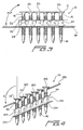
- the nail-type fastener collation strip assembly 10 is seen to comprise a plurality of laterally spaced nail-type fasteners 12 and a collation strip 14.
- the nail-type fasteners 12 are adapted to be driven into a suitable substrate member, not shown, which may be, for example, masonry, concrete, steel, wood, or the like, and each one of the nail-type fasteners 12 is seen to comprise a shank portion 16, a tip portion 18, and a head portion 20.
- each nail-type fastener 12 is seen to further comprise a plurality of annular rib-type members 22 such that together the rib-type members 22 provide a substantial portion of the external periphery of each shank portion 16 with a saw-tooth configuration as may be appreciated in longitudinal or axial cross-section.
- This saw-tooth configuration defined upon the external periphery of each shank portion 16 of each nail-type fastener 12 provides each nail-type fastener 12 with enhanced gripping properties and pull-out or withdrawal resistance once the nail-type fastener 12 has been driven into the particular substrate.
- the collation strip 14 is seen to further comprise a plurality of annular collar members 24 which are respectively disposed about an intermediate or axially central region of each shank portion 16 of each nail-type fastener 12 such that each collar member of the collation strip 14 is axially spaced from both the head portion 20 of its associated fastener 12 as well as from the tip portion 18 of the associated fastener 12.
- the collation strip 14 also comprises a plurality of transversely disposed web members 26 which integrally interconnect adjacent collar members 24, and each web member 26 is provided with a transversely extending rib member 28.
- the collation strip 14 may be fabricated from any one of a plurality of suitable thermoplstic materials, or a combination thereof, such as, for example, polyethylene (PE), polypropylene (PP), or polystyrene (PS), and the collation strip 14 is formed in accord-ance with known extrusion processing techniques.
- suitable thermoplstic materials such as, for example, polyethylene (PE), polypropylene (PP), or polystyrene (PS)
- each one of the collar members 24 has a substantially bell-shaped or frusto-conical configuration. More particularly, it is noted that each collar member 24 comprises an upper substantially cylindrical or tubular portion 30 and a radially outwardly flared portion 32 which terminates in a lower end annular ring portion 34. Still further, the annular ring portion 34 therefore defines a lower or undersurface portion 36.
- This particular structure of each collar member 24 serves at least two major functions in conjunction with the nail-type fastener collation strip assembly 10 of the present invention.
- the lower or undersurface portions 36 of the nail-type fasteners 12 serve to support the nail-type fastener collation strip assembly 10 upon horizontally disposed rail members or shear blocks 38,38 which are provided within the tool magazine and which project toward each other in a laterally spaced manner so as to define a space 40 therebetween.
- the lower shank and tip portions of the nail-type fasteners 12 can therefore depend downwardly through the space 40, and in this manner, the collated strip of nail-type fasteners 12 can be moved along the rail members or shear blocks 38,38, as indicated by the arrow F shown in FIGURE 2, by means of a known spring-biasing mechanism, not shown, such that leading ones of the nail-type fasteners 12 can be serially presented to and moved into a nosepiece bore 42 of the powered tool.
- a tool driver piston assembly 44 is adapted to be moved downwardly through or within the nosepiece bore 42 so as to individually sever the leading one of the nail-type fasteners 12 from the collation strip 14, and drive the severed leading one of the nail-type fasteners 12 through the nosepiece bore 42 and into the substrate.
- each nail-type fastener 12 With respect to the nose-piece bore 42 initially ensures that each nail-type fastener 12 will be presented to and inserted within the substrate in a substantially perpendicular manner with respect to the surface or face of the substrate into which the nail-type fastener 12 is being driven and inserted.
- the collation strip 14 and the collar members 24 thereof were not disposed upon substantially axially central regions of the shank portions 16 of the nail-type fasteners, that is, if the collation strip 14 and the collar members 24 were disposed upon upper regions of the shank portions 16 of the nail-type fasteners 12 so as to be disposed, for example, adjacent to the head portions 12 of the nail-type fasteners 12, then the depending shank portions 16 of the nail-type fasteners 12 would not necessarily be disposed in vertical planes and not necessarily presented to and inserted within the nosepiece bore 42 of the tool in the aforenoted desired coaxial manner with respect to the nosepiece bore 42 of the powered tool.
- each collar member 24 of the nail-type fastener collation strip assembly 10 of the present invention resides in the fact that the outer peripheral surface of the annular ring portion 34 has an outer diametrical extent which is substantially equal to the outer diametrical extent of the head portion 20 of each associated nail-type fastener 12.
- each nail-type fastener 12 is secondarily guided, in a coaxial manner with respect to the axis 46 of the nosepiece bore 42, through the nosepiece bore 42 of the tool so as to again ensure that each nail-type fastener 12 will be presented to and inserted within the substrate in a substantially perpendicular manner with respect to the surface or face of the substrate into with the nail-type fastener 12 is being driven and inserted.
- the outer diametrical extent of the head portion 20 of each nail-type fastener 12 is designated as HOD , as seen in FIGURE 1
- the outer diametrical extent of the annular guide ring portion 34 of each collar member 24 is designated as GROD as also seen in FIGURE 1 .
- the outer diametrical extent HOD of the head portion 20 of each nail-type fastener 12 is fabricated so as to be substantially equal to the outer diametrical extent GROD of the guide ring portion 34 of each collar member 24.
- each head portion 20 of each nail-type fastener 12 serves along with each guide ring portion 34 of each collar member 24 to define an axially separated two-point guidance system for coaxially guiding the movement of each nail-type fastener 12 with respect to the nosepiece bore 42 during the movement of each nail-type fastener 12 through the nosepiece bore 42 under the driving influence of the driver piston assembly 44.
- the second embodiment of the fastener collation strip assembly 110 of which the components correspond essentially to the various components of the collation strip assembly 10 disclosed within FIGURES 1-3 , and accordingly, such components of the collation strip assembly 110 which correspond to those components of the collation strip assembly 10 will be designated by similar reference characters except that they will be within the 100 series, does however present several apparent differences.
- the magazine assembly rail members 138 are disposed at a predetermined angle A with respect to the vertical longitudinal axes of the nail-type fasteners 112 wherein, for example, angle A is approximately 125°.
- collation strip collar members 124 are similarly disposed upon axially central regions of the shank portions 116 of the nail-type fasteners 112 with the longitudinal axes of the collar members 124 being coaxially disposed with respect to the longitudinal axes of the nail-type fasteners 112, the longitudinal transverse extent of the collation strip web portion 126, as well as the guide ring portions 134, are likewise disposed at predetermined angles A with respect to vertical planes such as, for example, the aforenoted angle of approximately 125°, so as to be disposed substantially parallel to the magazine rail members 138.
- the collation strip assembly 110 is supported within the tool magazine assembly as a result of the head portions 120 of the nail-type fasteners 112 being slidably supported upon the rail members 138.
- the head portions 120 of the nail-type fasteners 112 are vertically off-set with respect to each other such that the locus of the head portions 120 of the plurality of nail-type fasteners 112 is generally parallel to the rail members 138.
- the disposition of the collation strip 114 upon axially central portions of the nail-type fasteners 112 is in fact necessary to achieve the aforenoted two-point, axially spaced guided mode of the head-supported fasteners 112 because if, for example, the collation strip 114 was mounted, for example, upon upper end portions of the fasteners shanks 116 so as to be disposed adjacent to the head portions 120, the remaining dependent portions of the fastener shanks 116 would in effect be unconstrained whereby the fastener shanks 116 would not necessarily be disposed parallel to each other and with their longitudinal axes disposed vertically.
- the nail-type fasteners 112 would not be ensured to enter the nosepiece bore 42 of the powered tool in a substantially vertical, coaxial manner with respect to the longitudinal axis 46 of the nosepiece bore 42.
- the nail-type fasteners 112 in a manner similar to the nail-type fasteners 12, are ensured that when the same are driven through the nosepiece bore 42 of the powered tool, by means of the driver piston assembly 44, and into the particular substrate, the longitudinal axis of each nail-type fastener 112 will be disposed perpendicular to the face or surface of the substrate upon which the powered tool is disposed and into which the nail-type fastener 112 is being inserted.
- the collation strip comprises bell-shaped collar portions and is adapted to be mounted upon axially central shank portions of the nail-type fasteners such that the nail-type fasteners are constrained so as to be disposed parallel to each other and presented to the nosepice bore of the power tool in a coaxial manner with respect to the longitudinal axis of the nose-piece bore.
- the lower end guide ring portions of the bell-shaped collar portions cooperate together with the head portions of the nail-type fasteners in establishing a two-point guidance system for each nail-type fastener as each nail-type fastener is driven through the nosepiece bore of the power tool by means of the tool driver piston assembly.
- the lower end guide ring portions of the collar portions of the collation strip also serve to support the collation strip assembly upon the magazine rail members or shear blocks.
Landscapes
- Engineering & Computer Science (AREA)
- General Engineering & Computer Science (AREA)
- Mechanical Engineering (AREA)
- Chemical & Material Sciences (AREA)
- Combustion & Propulsion (AREA)
- Portable Nailing Machines And Staplers (AREA)
Abstract
Description
Claims (25)
- A collation strip for disposition upon a plurality of fasteners so as to form a collated strip of fasteners to be loaded into a tool magazine and be serially driven through a nosepiece bore (42) of the tool, comprising :a plurality of collar members (24) adapted to be respectively disposed upon a plurality of fasteners (12) ;a plurality of web members (26) integrally interconnecting said plurality of collar members (24) such that when said plurality of collar members (24) are respectively disposed upon the plurality of fasteners (12), said plurality of collar members (24), said plurality of web members (26), and said plurality of fasteners (12) form a collated strip of fasteners ;said plurality of collar members (24) respectively comprising a plurality of annular guide ring members (34) having an outer peripheral surface for engaging interior wall portions of the tool nosepiece bore (42) so as to guide each one of the plurality of fasteners (12) as each one of the plurality of fasteners is driven through the nosepiece bore (42) by a tool driver piston assembly (44).
- The collation strip as set forth in claim 1, wherein :
each one of said collar members (24) has a substantially bell-shaped cross-sectional configuration. - The collation strip as set forth in claim 2, wherein :
each one of said bell-shaped collar members (24) comprises a substantially cylindrical portion (30) adapted to be disposed upon a shank portion (16) of each one of the plurality of fasteners (12), and a radially outwardly flared portion (32) integrally interconnecting said substantially cylindrical portion (30) to said annular guide ring member (34). - The collation strip as set forth in claim 1, wherein :
said annular guide ring member (34) is disposed upon a lower end portion of each collar member (24). - The collation strip as set forth in claim 1, wherein :
said collation strip comprises an extrusion structure. - The collation strip as set forth in claim 5, wherein :
said collation strip is fabricated from a thermoplastic material. - The collation strip as set forth in claim 6, wherein :
said thermoplastic material is selected from the group comprising polyethylene, polypropylene, and polystyrene. - The collation strip as set forth in claim 1, wherein :
each one of said plurality of annular guide ring members (34) comprises an undersurface portion (36) for supporting said plurality of collar members (24) and the collated strip of fasteners upon rail members (38) of the tool magazine. - The collation strip as set forth in claim 3, wherein:said substantially cylindrical portion (30) is defined around a longitudinal axis ; andsaid undersurface portion (36) is disposed perpendicular to said longitudinal axis.
- The collation strip as set forth in claim 1, wherein :each one of said collar members (124) comprises a longitudinal axis ; andsaid web members (126) extend in a direction transverse to said longitudinal axes of said collar members (124) and together define a transverse axis which is disposed at a predetermined angle with respect to said longitudinal axes of said collar members (124).
- The collation strip as set forth in claim 10, wherein :
said transverse axis of said web members (126) is disposed at an angle of approximately 35° with respect to said longitudinal axes of said collar members (124). - A collated strip of fasteners for disposition within a tool magazine such that a plurality of fasteners (12) can be serially driven through a nosepiece bore (42) of a fastener-driving tool, comprising:a plurality of fasteners (12) respectively having shank portions (16) and head portions (20);a plurality of collar members (24) respectively disposed upon said shank portions (16) of said plurality of fasteners (12);a plurality of web members (26) integrally interconnecting said plurality of collar members (24) such that when said plurality of collar members (24) are respectively disposed upon said plurality of fasteners (12), said plurality of collar members (24), said plurality of web members (26), and said plurality of fasteners (12) form said collated strip of fasteners ;said plurality of collar members (24) respectively comprising a plurality of annular guide ring members (34) having an outer peripheral surface for engaging interior wall portions of said tool nosepiece bore (42) and for cooperating with said head portions (20) of said plurality of fasteners (12) so as together guide each one of said plurality of fasteners (12) in a coaxial manner with respect to the nosepiece bore (42) of the fastener-driving tool as each one of said plurality of fasteners (12) is driven through the nosepiece bore (42) of the fastener-driving tool by a tool driver piston assembly.
- The collated strip of fasteners as set forth in claim 12, wherein :
said plurality of collar members (24) are respectively mounted at substantially axially central regions of said shank portions (16) of said plurality of fasteners so as to be axially spaced from said head portions (20) of said plurality of fasteners (12) such that each one of said plurality of fasteners (12) is guided through the nosepiece bore (42) of the fastener-driving tool by means of a two-point axially-spaced guidance system. - The collated strip of fasteners as set forth in claim 12, wherein :each one of said annular guide ring members (34) of said collar members (24) has a first outer diametrical extent (GROD) ; andeach one of said head portions (20) of said plurality of fasteners has a second outer diametrical extent (HOD),said first and second outer diametrical extents (GROD, HOD) of said annular guide ring members of said collar members and said head portions of said plurality of fasteners are substantially equal to each other so as to define said two-point axially-spaced guidance system.
- The collated strip of fasteners as set forth in claim 12, wherein :
each one of said collar members (24) has a substantially-bell-shaped cross-sectional configuration. - The collated strip of fasteners as set forth in claim 15, wherein :
each one of said bell-shaped collar members (24) comprises a substantially cylindrical portion (30) adapted to be disposed upon said shank portion (16) of each one of said plurality of fasteners (12), and a radially outwardly flared portion (32) integrally interconnecting said substantially cylindrical portion (30) to said annular guide ring member (34). - The collated strip of fasteners as set forth is claim 12, wherein :
said annular guide ring member (34) is disposed upon a lower end portion of each collar member (24). - The collated strip of fasteners as set forth in claim 12, wherein :
said collar members (24) and said web members (26) of said collated strip of fasteners together comprise an extrusion structure. - The collated strip of fasteners as set forth in claim 18, wherein :
said extrusion structure is fabricated from a thermoplastic material. - The collated strip of fasteners as set forth in claim 19, wherein :
said thermoplastic material is selected from the group comprising polyethylene, polypropylene, and polystyrene. - The collated strip of fasteners as set forth in claim 12, wherein :
each one of said plurality of annular guide ring members (34) comprises an undersurface portion (36) for supporting said plurality of collar members (24) and said collated strip of fasteners upon rail members (38) of the tool magazine. - The collated strip of fasteners as set forth in claim 21, wherein :said substantially cylindrical portion (30) is defined around a longitudinal axis ; andsaid undersurface portion (36) is disposed perpendicular to said longitudinal axis.
- The collated strip of fasteners as set forth in claim 12, wherein :each one of said collar members (124) comprises a longitudinal axis ; andsaid web members (126) extend in a direction transverse to said longitudinal axes of said collar members (124) and together define a transverse axis which is disposed at a predetermined angle with respect to said longitudinal axes of said collar members (124).
- The collated strip of fasteners as set forth in claim 23, wherein :
said transverse axis of said web members (126) is disposed at an angle of approximately 35° with respect to said longitudinal axes of said collar members (124). - The collated strip of fasteners as set forth in claim 23, wherein :
said head portions (120) of said plurality of fasteners (112) are vertically offset with respect to each other so as to define a locus which is parallel to said transverse axis of said web members (126) and to enable the support of said collated strip of fasteners (112) by said head portions (120) upon rail members (138) of the fastener-driving tool.
Applications Claiming Priority (2)
| Application Number | Priority Date | Filing Date | Title |
|---|---|---|---|
| US09/675,221 US6394268B1 (en) | 2000-09-29 | 2000-09-29 | Nail-type fastener collation strip with fastener guide rings, and combination thereof |
| US675221 | 2000-09-29 |
Publications (2)
| Publication Number | Publication Date |
|---|---|
| EP1193405A2 true EP1193405A2 (en) | 2002-04-03 |
| EP1193405A3 EP1193405A3 (en) | 2004-01-14 |
Family
ID=24709537
Family Applications (1)
| Application Number | Title | Priority Date | Filing Date |
|---|---|---|---|
| EP01402492A Withdrawn EP1193405A3 (en) | 2000-09-29 | 2001-09-27 | Collation strip and collated strip of fasteners |
Country Status (4)
| Country | Link |
|---|---|
| US (1) | US6394268B1 (en) |
| EP (1) | EP1193405A3 (en) |
| AU (1) | AU772931B2 (en) |
| CA (1) | CA2355809A1 (en) |
Cited By (1)
| Publication number | Priority date | Publication date | Assignee | Title |
|---|---|---|---|---|
| DE102011075085A1 (en) * | 2011-05-02 | 2012-11-08 | Hilti Aktiengesellschaft | Fasteners strips |
Families Citing this family (17)
| Publication number | Priority date | Publication date | Assignee | Title |
|---|---|---|---|---|
| US6823990B2 (en) * | 2000-08-21 | 2004-11-30 | Power Products Iii, Llc | Nail holder strip |
| FR2831231B1 (en) * | 2001-10-18 | 2004-06-11 | Prospection & Inventions | FIXING ELEMENT BAND AND CHARGER FOR SUCH A BAND FOR DRIVING DEVICE FOR SUCH FIXING ELEMENTS |
| US6708821B2 (en) * | 2002-08-21 | 2004-03-23 | Illinois Tool Works Inc. | Fastener collation strip and debris exhaust mechanism |
| US20040118720A1 (en) * | 2002-12-18 | 2004-06-24 | Powers Fasteners, Inc. | Fastener carrier assembly and method of use |
| US7021462B2 (en) * | 2002-12-18 | 2006-04-04 | Powers Fasteners, Inc. | Fastener carrier assembly and method of use |
| FR2850895B1 (en) * | 2003-02-10 | 2006-03-03 | Prospection & Inventions | BAND OF FIXING ELEMENTS FOR SEALING APPARATUS WITH CHARGER FOR RECEIVING THE BAND, THE APPARATUS AND THE CHARGER |
| US7703649B2 (en) * | 2004-05-04 | 2010-04-27 | Illinois Tool Works, Inc. | Collations for fasteners of various lengths |
| US7971768B2 (en) * | 2004-05-04 | 2011-07-05 | Illinois Tool Works Inc. | Guidance system for fasteners |
| CA2613502A1 (en) * | 2005-06-24 | 2007-01-04 | James Murtha | Nail gun cartridge and driver and stud finder integrated with nail gun |
| US8360703B2 (en) * | 2006-05-12 | 2013-01-29 | Illinois Tool Works Inc. | Debris-free plastic collating strip for nails |
| US8333538B2 (en) * | 2006-05-12 | 2012-12-18 | Illinois Tool Works Inc. | Debris-free plastic collating strip for nails |
| USD605016S1 (en) | 2007-08-17 | 2009-12-01 | Simpson Strong-Tie Company, Inc. | Collation strip |
| US7963193B2 (en) * | 2008-11-29 | 2011-06-21 | John David Morgan | Adjustable multiple nail holder-extension |
| US8251686B1 (en) | 2008-12-02 | 2012-08-28 | Illinois Tool Works Inc. | Apparatus for making debris-free nail collation |
| US8033005B1 (en) | 2008-12-02 | 2011-10-11 | Illinois Tool Works Inc. | Method for making debris-free nail collation |
| US8387846B2 (en) * | 2009-06-08 | 2013-03-05 | Illinois Tool Works Inc | Fastening tool with blind guide work contact tip |
| JP2011179525A (en) * | 2010-02-26 | 2011-09-15 | Total Fastening Co Ltd | Connecting body of nail and connecting body of screw nail |
Family Cites Families (27)
| Publication number | Priority date | Publication date | Assignee | Title |
|---|---|---|---|---|
| US354462A (en) | 1886-12-14 | Tack-strip | ||
| US1263218A (en) | 1916-12-12 | 1918-04-16 | Albert C Fischer | Combined nail holding and spacing means. |
| US2982595A (en) | 1959-05-14 | 1961-05-02 | United Shoe Machinery Corp | Fastener inserting tools |
| US3357761A (en) | 1965-10-11 | 1967-12-12 | Signode Corp | Nail cartridge for driving tool magazines and flexible nail strip therefor |
| US3463304A (en) | 1967-09-06 | 1969-08-26 | Fastener Corp | Assembly or package of fasteners |
| US3736198A (en) * | 1971-02-08 | 1973-05-29 | W Leistner | Method of forming a nailing strip by applying a hot melt liquid plastic |
| US3823818A (en) | 1972-01-24 | 1974-07-16 | Monsanto Co | Belted preforms |
| US3802987A (en) | 1972-03-23 | 1974-04-09 | Corning Glass Works | Method of joining |
| US4167229A (en) | 1975-03-22 | 1979-09-11 | Karl M. Reich Maschinenfabrik Gmbh | Screw strip and method for forming the same |
| US4106618A (en) * | 1975-12-15 | 1978-08-15 | Haytayan Harry M | Nail assemblies |
| US4298121A (en) | 1980-08-08 | 1981-11-03 | Daichiku Company, Limited | Connected temporary fastening nails for use in the adhesive installation of ornamental plywood |
| JPS58178006A (en) * | 1982-04-09 | 1983-10-18 | 日立工機株式会社 | Connecting nail |
| DE3606901A1 (en) * | 1986-03-03 | 1987-09-10 | Hilti Ag | NAIL STRIP |
| US4913611A (en) | 1988-12-23 | 1990-04-03 | Leistner H E | Nailing strip |
| US5069340A (en) * | 1991-03-05 | 1991-12-03 | Illinois Tool Works Inc. | Strip of collated fasteners for fastener-driving tool |
| JP2593069Y2 (en) | 1993-10-13 | 1999-03-31 | 日本パワーファスニング株式会社 | Screw holding belt |
| DE19602789A1 (en) * | 1996-01-26 | 1997-07-31 | Hilti Ag | Nail strips for setting tool |
| US5713709A (en) | 1996-06-25 | 1998-02-03 | Huang; Shih Chang | Screw stay suitable for use with screws of different screw heads |
| US5775514A (en) | 1997-02-28 | 1998-07-07 | Lin; Jack | Screw band |
| US5931622A (en) | 1997-10-07 | 1999-08-03 | Illinois Tool Works Inc. | Fastener assembly with lateral end extension |
| US5931298A (en) | 1998-02-04 | 1999-08-03 | Huang; Shih Chang | Strip for supporting nails |
| DE19831378A1 (en) * | 1998-07-13 | 2000-01-20 | Hilti Ag | Nail magazine |
| DE19831371A1 (en) * | 1998-07-13 | 2000-01-20 | Hilti Ag | Nail magazine |
| AU754213B2 (en) * | 1998-09-18 | 2002-11-07 | Cetram Pty Limited | Power actuated tools with magazine feed |
| EP0987086A3 (en) * | 1998-09-18 | 2000-12-20 | Ramset Fasteners (Aust.) Pty. Ltd. | Power actuated tools with magazine feed |
| DE69919657T2 (en) * | 1998-11-06 | 2005-01-05 | Max Co. Ltd. | Banded fasteners |
| DE19860667A1 (en) * | 1998-12-29 | 2000-09-07 | Hilti Ag | Belt-like magazine for fasteners |
-
2000
- 2000-09-29 US US09/675,221 patent/US6394268B1/en not_active Expired - Fee Related
-
2001
- 2001-08-24 CA CA002355809A patent/CA2355809A1/en not_active Abandoned
- 2001-09-05 AU AU67111/01A patent/AU772931B2/en not_active Ceased
- 2001-09-27 EP EP01402492A patent/EP1193405A3/en not_active Withdrawn
Cited By (1)
| Publication number | Priority date | Publication date | Assignee | Title |
|---|---|---|---|---|
| DE102011075085A1 (en) * | 2011-05-02 | 2012-11-08 | Hilti Aktiengesellschaft | Fasteners strips |
Also Published As
| Publication number | Publication date |
|---|---|
| AU6711101A (en) | 2002-04-11 |
| CA2355809A1 (en) | 2002-03-29 |
| AU772931B2 (en) | 2004-05-13 |
| EP1193405A3 (en) | 2004-01-14 |
| US6394268B1 (en) | 2002-05-28 |
Similar Documents
| Publication | Publication Date | Title |
|---|---|---|
| US6394268B1 (en) | Nail-type fastener collation strip with fastener guide rings, and combination thereof | |
| US6814231B2 (en) | Strip of collated fasteners for fastener-driving tool | |
| AU2003231725B2 (en) | Fastener collation strip and debris exhaust mechanism | |
| EP0165674B1 (en) | Insert for a drywall | |
| US4932821A (en) | Nail retaining strip | |
| US5069340A (en) | Strip of collated fasteners for fastener-driving tool | |
| US5836732A (en) | Fastener assembly | |
| US5443345A (en) | Fastener-sleeve assembly and strip of collated fasteners | |
| AU709554B2 (en) | Fastener assembly with lateral end extension | |
| CN100408449C (en) | Fastener bracket assembly and method of use | |
| US7866931B2 (en) | Preset depth adapter and finger guard for screws and nails when installing sheetrock | |
| EP0264293A2 (en) | Collation strip | |
| US4106619A (en) | Nail clips | |
| AU2007249837B2 (en) | Debris-free plastic collating strip for nails | |
| US4971503A (en) | Plastic nails for automatic nail gun | |
| CA1086269A (en) | Fastener assembly | |
| JP2018532077A (en) | Fastener with transition zone and method of use | |
| NZ542837A (en) | Flute holder | |
| US5366082A (en) | Nail support strips | |
| GB2091368A (en) | Drive anchor | |
| US3455199A (en) | Eye-pin fasteners | |
| AU2005333514B8 (en) | Pin fastener for achieving metal-to-metal connections | |
| US20060280577A1 (en) | Multiple shank nail | |
| US20100021266A1 (en) | Directional fastener | |
| AU2005232309B2 (en) | Fastener collation strip and debris exhaust mechanism |
Legal Events
| Date | Code | Title | Description |
|---|---|---|---|
| PUAI | Public reference made under article 153(3) epc to a published international application that has entered the european phase |
Free format text: ORIGINAL CODE: 0009012 |
|
| AK | Designated contracting states |
Kind code of ref document: A2 Designated state(s): AT BE CH CY DE DK ES FI FR GB GR IE IT LI LU MC NL PT SE TR |
|
| AX | Request for extension of the european patent |
Free format text: AL;LT;LV;MK;RO;SI |
|
| PUAL | Search report despatched |
Free format text: ORIGINAL CODE: 0009013 |
|
| AK | Designated contracting states |
Kind code of ref document: A3 Designated state(s): AT BE CH CY DE DK ES FI FR GB GR IE IT LI LU MC NL PT SE TR |
|
| AX | Request for extension of the european patent |
Extension state: AL LT LV MK RO SI |
|
| RIC1 | Information provided on ipc code assigned before grant |
Ipc: 7F 16B 15/08 B Ipc: 7B 25C 1/18 B Ipc: 7F 16B 27/00 A |
|
| STAA | Information on the status of an ep patent application or granted ep patent |
Free format text: STATUS: THE APPLICATION HAS BEEN WITHDRAWN |
|
| 18W | Application withdrawn |
Effective date: 20040708 |