EP1193157A2 - Cable holding structure - Google Patents
Cable holding structure Download PDFInfo
- Publication number
- EP1193157A2 EP1193157A2 EP01308294A EP01308294A EP1193157A2 EP 1193157 A2 EP1193157 A2 EP 1193157A2 EP 01308294 A EP01308294 A EP 01308294A EP 01308294 A EP01308294 A EP 01308294A EP 1193157 A2 EP1193157 A2 EP 1193157A2
- Authority
- EP
- European Patent Office
- Prior art keywords
- cable
- flexible flat
- bent portion
- cylindrical portion
- flat cable
- Prior art date
- Legal status (The legal status is an assumption and is not a legal conclusion. Google has not performed a legal analysis and makes no representation as to the accuracy of the status listed.)
- Granted
Links
Images




Classifications
-
- H—ELECTRICITY
- H01—ELECTRIC ELEMENTS
- H01R—ELECTRICALLY-CONDUCTIVE CONNECTIONS; STRUCTURAL ASSOCIATIONS OF A PLURALITY OF MUTUALLY-INSULATED ELECTRICAL CONNECTING ELEMENTS; COUPLING DEVICES; CURRENT COLLECTORS
- H01R35/00—Flexible or turnable line connectors, i.e. the rotation angle being limited
- H01R35/02—Flexible line connectors without frictional contact members
- H01R35/025—Flexible line connectors without frictional contact members having a flexible conductor wound around a rotation axis
-
- H—ELECTRICITY
- H01—ELECTRIC ELEMENTS
- H01R—ELECTRICALLY-CONDUCTIVE CONNECTIONS; STRUCTURAL ASSOCIATIONS OF A PLURALITY OF MUTUALLY-INSULATED ELECTRICAL CONNECTING ELEMENTS; COUPLING DEVICES; CURRENT COLLECTORS
- H01R12/00—Structural associations of a plurality of mutually-insulated electrical connecting elements, specially adapted for printed circuits, e.g. printed circuit boards [PCB], flat or ribbon cables, or like generally planar structures, e.g. terminal strips, terminal blocks; Coupling devices specially adapted for printed circuits, flat or ribbon cables, or like generally planar structures; Terminals specially adapted for contact with, or insertion into, printed circuits, flat or ribbon cables, or like generally planar structures
- H01R12/70—Coupling devices
- H01R12/77—Coupling devices for flexible printed circuits, flat or ribbon cables or like structures
- H01R12/771—Details
- H01R12/772—Strain relieving means
Definitions
- the present invention relates to a cable holding structure for holding a flexible flat cable (FFC) at predetermined positions thereof. More particularly, the invention relates to a cable holding structure adapted to hold a bent portion of a flexible flat cable connecting a steering wheel side of a steering wheel portion of an automobile to a steering column side thereof.
- FFC flexible flat cable
- this cable structure comprises a rotor (or rotator) 1 including an inner cylindrical portion (or internal cylindrical member) 1a, and a stator 2 which includes an outer cylindrical portion (or outside cylindrical member) 2a surrounding the inner cylindrical portion in such a manner as to provide a space having predetermined width therebetween.
- This cable structure further comprises a flexible flat cable 3 (hereunder referred to simply as a cable 3) accommodated in the annular space K provided between the inner cylindrical portion 1a and the outer cylindrical portion 2a in such a manner as to be wound like a spiral along this space K, and a nearly C-shaped moving element 4 rotationally movably provided along this space K and adapted so as to turn back the cable 3 at an opening portion 4a.
- a flexible flat cable 3 hereunder referred to simply as a cable 3
- a cable 3 accommodated in the annular space K provided between the inner cylindrical portion 1a and the outer cylindrical portion 2a in such a manner as to be wound like a spiral along this space K
- a nearly C-shaped moving element 4 rotationally movably provided along this space K and adapted so as to turn back the cable 3 at an opening portion 4a.
- the rotor 1 is provided with a holder portion 1b for fitting and holding a cable holding element 5 provided in an inner peripheral end portion 3a of the cable 3.
- a cover member 6 is attached to the stator 2 in such a manner as to cover the topside of the space K and the periphery of the outer cylindrical portion 2a.
- the cover member 6 comprises an upper cover 6a for covering the topside of the space K, and a cylindrical portion 6b surrounding the periphery of the outer cylindrical portion 2a.
- the cover member 6 is adapted in such a way as not to perform relative rotation with respect to the stator 2.
- an opening portion 6c is formed in the central portion of the upper cover 6a.
- a lower cover 2b for covering the lower side of the space K is formed in such a manner as to be integral with the outer cylindrical portion 2a.
- a holder portion 2c for holding the cable holding element 5 provided in the cable 3 is provided in the outer cylindrical portion 2a.
- an externally introducing cover 8 for externally introducing the cable 3 is rotatably provided on the topside of the cover member 6.
- the externally introducing cover 8 is connected to the inner cylindrical portion 1a through the opening portion 6c of the cover member 6, and adapted to rotate together with the inner cylindrical portion 1a.
- a connector holder portion 8a for holding an inner connector 9 of the cable 3 is provided in this externally introducing cover 8.
- a portion of the cable 3 held by the cable holding element 5 has a bent portion 3b bent at right angle .
- the cable 3 is formed so that this bent portion 3b forms the boundary between a part extending in a direction X and another part extending in a direction Y, which are orthogonal to each other. Further, the former part of the cable 3 extending in the direction X is placed in the annular space k, and the latter part of the cable 3 extending in the direction Y is led to the externally introducing cover 8.
- the cable 3 is fixed to a connector holder 8a through the inner connector 9.
- the cable holding element 5 is formed like a square block.
- a groove 5a into which the bent portion 3b of the cable 3 is inserted is formed in this block.
- a first opening portion 5b through which the part of the cable 3 extending in the direction X passes, and a second opening portion 5c through which the part of the cable 3 extending in the direction Y passes are formed in the groove 5a.
- a stopper 5d abutting a side edge portion 3c of the cable 3, which extends in the direction Y, for preventing this bent portion 3c from going out therefrom in the direction X is provided in the first opening portion 5b.
- the related cable holding structure has encountered the problems that a backlash in the upward or downward direction is occurred in a portion of the cable holding element 5, into which the holder portion 1b of the rotor 1 is inserted, that because the cable 3 is rotatably and movably provided along the space K and turned back in an opening portion 4a, the turned-back portion is liable to upwardly and downwardly swing, and the cable 3 is shaken upwardly and downwardly, and that abnormal noises are generated by performing sliding operations between the cabled 3 and each of the cover member 6 and the rotor 1.
- the rotor 1 has a space (that is, the holder portion 1b) for accommodating the cable holding element 5.
- the rotor 1 has a space (that is, the holder portion 1b) for accommodating the cable holding element 5.
- an object of the invention is to provide a cable holding structure, which provides good assemblability and is enabled to reduce the number of components and to cope with an increase in the number of circuits corresponding to flexible flat cables.
- a cable holding structure (hereunder referred to as a first structure), in which a bent portion is formed by bending a band-like flexible flat cable at a predetermined portion and is then held by a first one of members each performing relative rotation.
- the first structure comprises a groove portion formed in the first one of the members and adapted so that the bent portion is inserted into the groove portion, a first slit formed in the groove portion and adapted so that the flexible flat cable extending in a first direction from the bent portion is inserted thereinto, a second slit formed in the second slit formed in the groove portion and adapted so that the flexible flat cable extending in a second direction from the bent portion is inserted thereinto, a first stopper provided in the first slit in such a way as to abut against a side edge portion of the flexible flat cable extending in the second direction from the bent portion, and a second stopper provided in the second slit in such a manner as to abut against a side edge portion of the flexible flat cable extending in the first direction from the bent portion.
- the first stopper abuts against the side edge portion of the flexible flat cable extending in the second direction from the bent portion in the first slit during this structure is in a state in which the bent portion of this flexible flat cable is inserted into the groove portion formed in the one of members.
- this cable holding structure has an advantageous effect in that the bent portion is prevented from slipping off therefrom in a direction.
- the second stopper formed in the second slit abuts against the side edge portion of the flexible flat cable extending in the first direction from the bent portion.
- this structure has an advantageous effect in that the second stopper is prevented from slipping off therefrom in the second direction. Consequently, the flexible flat cable is prevented from being shaken with respect to the one of the members.
- the flexible flat cable and the one of the members are prevented from performing a sliding operation therebetween to thereby generate abnormal noises.
- the first structure has an advantageous effect in that the number of components is reduced by assembling the bent portion to the one of the members.
- the one of members is a rotator, which is fixed to a steering shaft and has an inner cylindrical portion.
- the second one of members is a stator, which is fixed to a steering column and has an outer cylindrical portion.
- the flexible flat cable extended from the bent portion in the first direction is disposed between the inner cylindrical portion and the outer cylindrical portion like a spiral.
- the bent portion of the flexible flat cable is assembled directly to the rotator without using a holding member.
- the second structure has an advantageous effect in that the structure is enabled to cope with an increase in the number of circuits corresponding to the flexible flat cables.
- the groove portion is formed in a wall portion of the inner cylindrical portion formed in the rotator. Further, the first slit is formed in a peripheral wall of the inner cylindrical portion.
- the groove portion is formed in the wall part of the inner cylindrical portion of the rotator.
- FIG. 1 is an exploded perspective view illustrating the relay apparatus according to the invention.
- FIG. 2 is an exploded perspective view illustrating a cable holding structure to be applied to the relay apparatus.
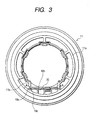
- FIG. 3 is a plan view illustrating a rotator (or rotor) serving as a cable holding portion.
- FIG. 4 is a sectional view taken on line A-A of FIG. 3, which shows a cable holding state.
- this relay apparatus 10 comprises a synthetic resin rotator 11 including an inner cylindrical portion (an internal cylindrical member) 11a, and a stator 12 including an outer cylindrical portion (or outside cylindrical member) 12a surrounding the inner cylindrical portion in such a manner as to provide a space of predetermined width therebetween.
- This relay apparatus 10 further comprises a flexible flat cable 13 (hereunder referred to simply as a cable 13) accommodated in the ring-like space K provided between the inner cylindrical portion 11a and the outer cylindrical portion 12a in such a manner as to be wound like a spiral along this space K, and a nearly C-shaped synthetic resin moving element 14 rotationally movably provided along this space K and adapted in such a way as to turn back the cable 13 in an opening portion 14a.
- a flexible flat cable 13 hereunder referred to simply as a cable 13
- a synthetic resin cover member 15 is provided on the stator 12 in such a manner as to cover the topside of the space K and the periphery of the outer cylindrical portion 12a.
- This cover member 15 comprises an upper cover 15a for covering the topside of the space K, and a cylindrical portion 15b surrounding the periphery of the outer cylindrical portion 12a.
- the cover member 15 is adapted in such a way as not to perform relative rotation with respect to the stator 12.
- an opening portion 15c is formed in the central portion of the upper cover 15a.
- a lower cover 12b for covering the lower side of the space K is formed in such a manner as to be integral with the outer cylindrical portion 12a.
- a holder portion 12c for holding the cable holding element 16 provided in the cable 13 is provided in the outer cylindrical portion 12a.
- An externally introducing synthetic resin cover 17 for externally introducing the cable 13 is rotatably provided on the topside of the cover member 15.
- This externally introducing cover 17 is connected to the inner cylindrical portion 11a through the opening portion 15c of the cover member 15, and adapted to rotate together with the inner cylindrical portion 11a.
- a connector holder portion 17a for holding an inner connector 18 of the cable 13 is provided in this externally introducing cover 17.
- the cable 13 is formed so that a bent portion 13a forms the boundary between a part extending in a direction X and another part extending in one direction Y, which are orthogonal to each other. Further, the former part of the cable 13, which extends in the direction X, is placed in the ring-like space k, while the latter part of the cable 13, which extends in the direction Y, is led to the externally introducing cover 17. The cable 13 is fixed to a connector holder 17a through the inner connector 18.
- a grove-like holder portion (or groove portion) 19 into which the bent portion 13a of the cable 13 is inserted is formed in the inner cylindrical portion 11a of the rotator 11. Further, this holder portion 19 is formed by being surrounded by the wall of the inner cylindrical portion 11a and a plate-like inner wall 20 formed on the inner side of the inner cylindrical portion 11a.
- aslit (that is, a first slit) 19a into which the cable 3 extending in the one direction X is inserted in the direction of width thereof, is formed.
- An inwardly concave groove 11b is formed along the direction Y on the one side in the direction of circumference of the holder portion 19 in the inner cylindrical portion 11a of the rotator 11.
- the slit 19a is formed in the groove wall of this concave groove 11b.
- the holder portion 19 includes an opening portion (that is, a second slit) 19b, through which the cable 13 extending in another direction Y passes.
- the slit 19a is set in a gap of a width that is equal to the thickness of the cable 13.
- a stopper that is, a first stopper
- 19c is formed on an outer opening edge of the slit 19a and is adapted to abut against the side edge portion 13b of the cable 13 extending in the other direction Y for preventing this bent portion 13a from going off in the one direction X.
- a slip-off preventing projection that is, a second stopper
- 21 is provided on the upper opening edge (that is, a part thereof facing the opening portion 19b) in such a way as to protrude therefrom.
- the slip-off preventing projection 21 has the functions of abutting against an upper edge portion (that is, a side edge portion) 13c of the cable 13 extending in the one direction X from the bent portion 13a, and preventing this bent portion 13a from going off in the other direction Y.
- Bottom plate portions 22 and 23 respectively having slopes 22a and 23a provided along the bottom edge of the inserted bent portion 13a are integrally formed on the bottom portion of the holder portion 19 in such a way as to project therefrom.
- the insertion of the bent portion 13a of the cable 13 into the holder portion 19 formed in the inner cylindrical portion 11a of the rotator 11 causes the stopper 19c to abut against the side edge portion 13b of the cable 13 extending in the latter direction Y from the bent portion 13a.
- the slip-off projection 21 is placed in such a manner as to abut against the side edge portion 13c of the cable 13 extending in the direction of the one direction X from the bent portion 13a. Consequently, the cable 13 is not shaken upwardly and downwardly with respect to the rotator 11.
- the sliding operations are restrained from being performed between the cable 13 and each of the rotator 11 and the cover member 15. Consequently, abnormal noises are prevented from being generated as the steering wheel is turned.
- the aforementioned embodiment is constructed so that the cable 13 is inserted directly into the holder portion 19 of the rotator 11 without using the cable holding element.
- the embodiment easily copes with the case that the number of circuits corresponding to the cables 13 increases.
- the cable 13 can be held without using the cable holding element.
- the assemblability is enhanced.
- the number of components is reduced.
- the relay apparatus 10 has the moving element 14.
- the invention can be applied to an apparatus that does not have the moving element 14.
- the first stopper abuts against the side edge portion of the cable to thereby prevent the bent portion from slipping off in a direction.
- the second stopper abuts against the side edge portion of the flexible flat cable extending a direction from the bent portion.
- the bent portion is prevented from going off therefrom in the one direction or in the other direction. Consequently, the cable is reliably held. Therefore, the flexible flat cable is prevented from being shaken with respect to one of the relative rotation members.
- the flexible flat cable and the one of the members are prevented from performing a sliding operation therebetween to thereby generate abnormal noises.
- the first structure has an advantageous effect in that the number of components is reduced by assembling the bent portion and the one of the members .
- the bent portion of the flexible flat cable is assembled directly to the rotator without using a holding member.
- the second structure has an advantageous effect in that the structure is enabled to cope with an increase in the number of circuits corresponding to the flexible flat cables. This enables an increase in the number of signal input/output paths and electric power supply paths provided between the steering wheel side and the steering column.
- the groove portion is formed in the wall part of the inner cylindrical portion of the rotator.
Landscapes
- Steering Controls (AREA)
- Electric Cable Arrangement Between Relatively Moving Parts (AREA)
- Installation Of Indoor Wiring (AREA)
Abstract
Description
Claims (3)
- A cable holding structure, in which a bent portion is formed by bending a band-like flexible flat cable at a predetermined portion and held by a first one of members each performing relative rotation, the cable holding structure comprising:a groove portion formed in the first one of members and adapted so that the bent portion is inserted into the groove portion;a first slit formed in the groove portion and adapted so that the flexible flat cable extending in a first direction from the bent portion is inserted thereinto;a second slit formed in the groove portion and adapted so that the flexible flat cable extending in a second direction substantially perpendicular to the first direction from the bent portion is inserted thereinto;a first stopper provided in the first slit for abutting against a side edge portion of the flexible flat cable extending in the second direction from the bent portion; anda second stopper provided in the second slit for abutting against a side edge portion of the flexible flat cable extending in the first direction from the bent portion.
- The cable holding structure according to claim 1, whereinthe first one of members is a rotator fixed to a steering shaft and including an inner cylindrical portion,a second one of members is a stator fixed to a steering column and including an outer cylindrical portion, andthe flexible flat cable extended from the bent portion in the first direction is disposed between the inner cylindrical portion and the outer cylindrical portion like a spiral.
- The cable holding structure according to claim 2, wherein the groove portion is formed in a wall portion of the inner cylindrical portion formed in said rotator, and wherein said first slit is formed in a peripheral wall of said inner cylindrical portion.
Applications Claiming Priority (2)
| Application Number | Priority Date | Filing Date | Title |
|---|---|---|---|
| JP2000302480A JP2002118946A (en) | 2000-10-02 | 2000-10-02 | Cable holding structure |
| JP2000302480 | 2000-10-02 |
Publications (3)
| Publication Number | Publication Date |
|---|---|
| EP1193157A2 true EP1193157A2 (en) | 2002-04-03 |
| EP1193157A3 EP1193157A3 (en) | 2003-02-12 |
| EP1193157B1 EP1193157B1 (en) | 2006-03-08 |
Family
ID=18783826
Family Applications (1)
| Application Number | Title | Priority Date | Filing Date |
|---|---|---|---|
| EP01308294A Expired - Lifetime EP1193157B1 (en) | 2000-10-02 | 2001-09-28 | Cable holding structure |
Country Status (4)
| Country | Link |
|---|---|
| US (1) | US20020038842A1 (en) |
| EP (1) | EP1193157B1 (en) |
| JP (1) | JP2002118946A (en) |
| DE (1) | DE60117730T2 (en) |
Families Citing this family (2)
| Publication number | Priority date | Publication date | Assignee | Title |
|---|---|---|---|---|
| US6586673B1 (en) | 2002-05-24 | 2003-07-01 | Hernan F. Socarras | Service loop tray and assembly for low voltage cables |
| JP2025038605A (en) * | 2023-09-07 | 2025-03-19 | 古河電気工業株式会社 | Power supply device |
Family Cites Families (3)
| Publication number | Priority date | Publication date | Assignee | Title |
|---|---|---|---|---|
| JPH08185950A (en) * | 1995-01-05 | 1996-07-16 | Yazaki Corp | Fixing structure of flat cable to cylindrical rotating body |
| JP2863104B2 (en) * | 1995-01-12 | 1999-03-03 | 矢崎総業株式会社 | Relay device between relative rotating members |
| JP3112424B2 (en) * | 1996-01-18 | 2000-11-27 | 矢崎総業株式会社 | Cable holding structure |
-
2000
- 2000-10-02 JP JP2000302480A patent/JP2002118946A/en active Pending
-
2001
- 2001-09-28 DE DE60117730T patent/DE60117730T2/en not_active Expired - Lifetime
- 2001-09-28 EP EP01308294A patent/EP1193157B1/en not_active Expired - Lifetime
- 2001-10-02 US US09/968,668 patent/US20020038842A1/en not_active Abandoned
Also Published As
| Publication number | Publication date |
|---|---|
| EP1193157B1 (en) | 2006-03-08 |
| DE60117730T2 (en) | 2007-01-25 |
| US20020038842A1 (en) | 2002-04-04 |
| JP2002118946A (en) | 2002-04-19 |
| DE60117730D1 (en) | 2006-05-04 |
| EP1193157A3 (en) | 2003-02-12 |
Similar Documents
| Publication | Publication Date | Title |
|---|---|---|
| CN204304183U (en) | Rotary connector | |
| EP1650838A1 (en) | Rotary connector | |
| JP2921734B2 (en) | Electrical connection between steering wheel and steering column | |
| JPH09151923A (en) | Cover fixing structure to the end surface of the cylindrical body | |
| US9653234B2 (en) | Multidirectional switch | |
| JPH0864324A (en) | Electrical connection device between steering wheel and steering column | |
| WO2012111753A1 (en) | Lever connector | |
| JP2003319535A (en) | Grommet | |
| EP1193157B1 (en) | Cable holding structure | |
| US6341969B1 (en) | Rotary connector | |
| JPH11144564A (en) | Operating mechanism of rotary type electric component | |
| JP4262665B2 (en) | Electrical connector with cover | |
| JP3700484B2 (en) | Rotating connector | |
| US20200211805A1 (en) | Lever switch device | |
| US12170429B2 (en) | Rotary connector having an external connection terminal movable in multiple directions | |
| CN104833379B (en) | The manufacture method of detector and detector | |
| JP3535654B2 (en) | Connector and its mounting structure | |
| JP2009146794A (en) | On-vehicle plug terminal box | |
| JPH10155789A (en) | Ultrasonic probe | |
| JPH09326283A (en) | Electrical connection device between rotating body and fixed body | |
| JP6141560B2 (en) | Electronic equipment and assembly structure thereof | |
| US20260045430A1 (en) | Rotary electric component | |
| CN111095747A (en) | motor unit | |
| JP2001102145A (en) | Rotating connector | |
| JP2000004084A (en) | Hinge structure of electronic device and electronic device |
Legal Events
| Date | Code | Title | Description |
|---|---|---|---|
| PUAI | Public reference made under article 153(3) epc to a published international application that has entered the european phase |
Free format text: ORIGINAL CODE: 0009012 |
|
| AK | Designated contracting states |
Kind code of ref document: A2 Designated state(s): AT BE CH CY DE DK ES FI FR GB GR IE IT LI LU MC NL PT SE TR |
|
| AX | Request for extension of the european patent |
Free format text: AL;LT;LV;MK;RO;SI |
|
| PUAL | Search report despatched |
Free format text: ORIGINAL CODE: 0009013 |
|
| AK | Designated contracting states |
Designated state(s): AT BE CH CY DE DK ES FI FR GB GR IE IT LI LU MC NL PT SE TR |
|
| AX | Request for extension of the european patent |
Extension state: AL LT LV MK RO SI |
|
| 17P | Request for examination filed |
Effective date: 20030729 |
|
| AKX | Designation fees paid |
Designated state(s): AT BE CH LI |
|
| RBV | Designated contracting states (corrected) |
Designated state(s): DE FR GB |
|
| 17Q | First examination report despatched |
Effective date: 20031014 |
|
| REG | Reference to a national code |
Ref country code: DE Ref legal event code: 8566 |
|
| GRAP | Despatch of communication of intention to grant a patent |
Free format text: ORIGINAL CODE: EPIDOSNIGR1 |
|
| GRAS | Grant fee paid |
Free format text: ORIGINAL CODE: EPIDOSNIGR3 |
|
| GRAA | (expected) grant |
Free format text: ORIGINAL CODE: 0009210 |
|
| AK | Designated contracting states |
Kind code of ref document: B1 Designated state(s): DE FR GB |
|
| REG | Reference to a national code |
Ref country code: GB Ref legal event code: FG4D |
|
| REF | Corresponds to: |
Ref document number: 60117730 Country of ref document: DE Date of ref document: 20060504 Kind code of ref document: P |
|
| ET | Fr: translation filed | ||
| PLBE | No opposition filed within time limit |
Free format text: ORIGINAL CODE: 0009261 |
|
| STAA | Information on the status of an ep patent application or granted ep patent |
Free format text: STATUS: NO OPPOSITION FILED WITHIN TIME LIMIT |
|
| 26N | No opposition filed |
Effective date: 20061211 |
|
| REG | Reference to a national code |
Ref country code: FR Ref legal event code: PLFP Year of fee payment: 16 |
|
| REG | Reference to a national code |
Ref country code: FR Ref legal event code: PLFP Year of fee payment: 17 |
|
| REG | Reference to a national code |
Ref country code: FR Ref legal event code: PLFP Year of fee payment: 18 |
|
| PGFP | Annual fee paid to national office [announced via postgrant information from national office to epo] |
Ref country code: DE Payment date: 20180918 Year of fee payment: 18 Ref country code: FR Payment date: 20180813 Year of fee payment: 18 |
|
| PGFP | Annual fee paid to national office [announced via postgrant information from national office to epo] |
Ref country code: GB Payment date: 20180926 Year of fee payment: 18 |
|
| REG | Reference to a national code |
Ref country code: DE Ref legal event code: R119 Ref document number: 60117730 Country of ref document: DE |
|
| PG25 | Lapsed in a contracting state [announced via postgrant information from national office to epo] |
Ref country code: DE Free format text: LAPSE BECAUSE OF NON-PAYMENT OF DUE FEES Effective date: 20200401 |
|
| GBPC | Gb: european patent ceased through non-payment of renewal fee |
Effective date: 20190928 |
|
| PG25 | Lapsed in a contracting state [announced via postgrant information from national office to epo] |
Ref country code: FR Free format text: LAPSE BECAUSE OF NON-PAYMENT OF DUE FEES Effective date: 20190930 Ref country code: GB Free format text: LAPSE BECAUSE OF NON-PAYMENT OF DUE FEES Effective date: 20190928 |