EP1193106A1 - Vehicle running control device and vehicle - Google Patents
Vehicle running control device and vehicle Download PDFInfo
- Publication number
- EP1193106A1 EP1193106A1 EP99919537A EP99919537A EP1193106A1 EP 1193106 A1 EP1193106 A1 EP 1193106A1 EP 99919537 A EP99919537 A EP 99919537A EP 99919537 A EP99919537 A EP 99919537A EP 1193106 A1 EP1193106 A1 EP 1193106A1
- Authority
- EP
- European Patent Office
- Prior art keywords
- vehicle
- distance
- speed
- running
- preceding vehicle
- Prior art date
- Legal status (The legal status is an assumption and is not a legal conclusion. Google has not performed a legal analysis and makes no representation as to the accuracy of the status listed.)
- Granted
Links
- 230000005540 biological transmission Effects 0.000 claims description 23
- 238000002485 combustion reaction Methods 0.000 claims description 18
- 238000001514 detection method Methods 0.000 claims description 18
- 230000004048 modification Effects 0.000 claims description 14
- 238000012986 modification Methods 0.000 claims description 14
- 238000000034 method Methods 0.000 description 21
- 230000008569 process Effects 0.000 description 20
- 230000013011 mating Effects 0.000 description 8
- 230000007246 mechanism Effects 0.000 description 8
- 230000008859 change Effects 0.000 description 7
- 230000001276 controlling effect Effects 0.000 description 6
- 230000001133 acceleration Effects 0.000 description 4
- 239000000446 fuel Substances 0.000 description 3
- 230000004044 response Effects 0.000 description 3
- 230000004913 activation Effects 0.000 description 2
- 238000002347 injection Methods 0.000 description 2
- 239000007924 injection Substances 0.000 description 2
- 230000008929 regeneration Effects 0.000 description 2
- 238000011069 regeneration method Methods 0.000 description 2
- 230000008878 coupling Effects 0.000 description 1
- 238000010168 coupling process Methods 0.000 description 1
- 238000005859 coupling reaction Methods 0.000 description 1
- 230000003247 decreasing effect Effects 0.000 description 1
- 238000010586 diagram Methods 0.000 description 1
- 238000011156 evaluation Methods 0.000 description 1
- 230000007935 neutral effect Effects 0.000 description 1
- 230000001105 regulatory effect Effects 0.000 description 1
- 238000009738 saturating Methods 0.000 description 1
- 230000005236 sound signal Effects 0.000 description 1
- 230000001131 transforming effect Effects 0.000 description 1
Images





Classifications
-
- F—MECHANICAL ENGINEERING; LIGHTING; HEATING; WEAPONS; BLASTING
- F02—COMBUSTION ENGINES; HOT-GAS OR COMBUSTION-PRODUCT ENGINE PLANTS
- F02D—CONTROLLING COMBUSTION ENGINES
- F02D29/00—Controlling engines, such controlling being peculiar to the devices driven thereby, the devices being other than parts or accessories essential to engine operation, e.g. controlling of engines by signals external thereto
- F02D29/02—Controlling engines, such controlling being peculiar to the devices driven thereby, the devices being other than parts or accessories essential to engine operation, e.g. controlling of engines by signals external thereto peculiar to engines driving vehicles; peculiar to engines driving variable pitch propellers
-
- B—PERFORMING OPERATIONS; TRANSPORTING
- B60—VEHICLES IN GENERAL
- B60K—ARRANGEMENT OR MOUNTING OF PROPULSION UNITS OR OF TRANSMISSIONS IN VEHICLES; ARRANGEMENT OR MOUNTING OF PLURAL DIVERSE PRIME-MOVERS IN VEHICLES; AUXILIARY DRIVES FOR VEHICLES; INSTRUMENTATION OR DASHBOARDS FOR VEHICLES; ARRANGEMENTS IN CONNECTION WITH COOLING, AIR INTAKE, GAS EXHAUST OR FUEL SUPPLY OF PROPULSION UNITS IN VEHICLES
- B60K31/00—Vehicle fittings, acting on a single sub-unit only, for automatically controlling vehicle speed, i.e. preventing speed from exceeding an arbitrarily established velocity or maintaining speed at a particular velocity, as selected by the vehicle operator
- B60K31/0008—Vehicle fittings, acting on a single sub-unit only, for automatically controlling vehicle speed, i.e. preventing speed from exceeding an arbitrarily established velocity or maintaining speed at a particular velocity, as selected by the vehicle operator including means for detecting potential obstacles in vehicle path
-
- B—PERFORMING OPERATIONS; TRANSPORTING
- B60—VEHICLES IN GENERAL
- B60W—CONJOINT CONTROL OF VEHICLE SUB-UNITS OF DIFFERENT TYPE OR DIFFERENT FUNCTION; CONTROL SYSTEMS SPECIALLY ADAPTED FOR HYBRID VEHICLES; ROAD VEHICLE DRIVE CONTROL SYSTEMS FOR PURPOSES NOT RELATED TO THE CONTROL OF A PARTICULAR SUB-UNIT
- B60W30/00—Purposes of road vehicle drive control systems not related to the control of a particular sub-unit, e.g. of systems using conjoint control of vehicle sub-units
- B60W30/14—Adaptive cruise control
- B60W30/16—Control of distance between vehicles, e.g. keeping a distance to preceding vehicle
-
- B—PERFORMING OPERATIONS; TRANSPORTING
- B60—VEHICLES IN GENERAL
- B60W—CONJOINT CONTROL OF VEHICLE SUB-UNITS OF DIFFERENT TYPE OR DIFFERENT FUNCTION; CONTROL SYSTEMS SPECIALLY ADAPTED FOR HYBRID VEHICLES; ROAD VEHICLE DRIVE CONTROL SYSTEMS FOR PURPOSES NOT RELATED TO THE CONTROL OF A PARTICULAR SUB-UNIT
- B60W30/00—Purposes of road vehicle drive control systems not related to the control of a particular sub-unit, e.g. of systems using conjoint control of vehicle sub-units
- B60W30/14—Adaptive cruise control
- B60W30/16—Control of distance between vehicles, e.g. keeping a distance to preceding vehicle
- B60W30/17—Control of distance between vehicles, e.g. keeping a distance to preceding vehicle with provision for special action when the preceding vehicle comes to a halt, e.g. stop and go
-
- B—PERFORMING OPERATIONS; TRANSPORTING
- B60—VEHICLES IN GENERAL
- B60W—CONJOINT CONTROL OF VEHICLE SUB-UNITS OF DIFFERENT TYPE OR DIFFERENT FUNCTION; CONTROL SYSTEMS SPECIALLY ADAPTED FOR HYBRID VEHICLES; ROAD VEHICLE DRIVE CONTROL SYSTEMS FOR PURPOSES NOT RELATED TO THE CONTROL OF A PARTICULAR SUB-UNIT
- B60W30/00—Purposes of road vehicle drive control systems not related to the control of a particular sub-unit, e.g. of systems using conjoint control of vehicle sub-units
- B60W30/18—Propelling the vehicle
- B60W30/18009—Propelling the vehicle related to particular drive situations
- B60W30/18109—Braking
- B60W30/18127—Regenerative braking
-
- F—MECHANICAL ENGINEERING; LIGHTING; HEATING; WEAPONS; BLASTING
- F02—COMBUSTION ENGINES; HOT-GAS OR COMBUSTION-PRODUCT ENGINE PLANTS
- F02D—CONTROLLING COMBUSTION ENGINES
- F02D41/00—Electrical control of supply of combustible mixture or its constituents
- F02D41/02—Circuit arrangements for generating control signals
- F02D41/021—Introducing corrections for particular conditions exterior to the engine
- F02D41/0215—Introducing corrections for particular conditions exterior to the engine in relation with elements of the transmission
- F02D41/0225—Introducing corrections for particular conditions exterior to the engine in relation with elements of the transmission in relation with the gear ratio or shift lever position
-
- B—PERFORMING OPERATIONS; TRANSPORTING
- B60—VEHICLES IN GENERAL
- B60W—CONJOINT CONTROL OF VEHICLE SUB-UNITS OF DIFFERENT TYPE OR DIFFERENT FUNCTION; CONTROL SYSTEMS SPECIALLY ADAPTED FOR HYBRID VEHICLES; ROAD VEHICLE DRIVE CONTROL SYSTEMS FOR PURPOSES NOT RELATED TO THE CONTROL OF A PARTICULAR SUB-UNIT
- B60W2554/00—Input parameters relating to objects
- B60W2554/80—Spatial relation or speed relative to objects
- B60W2554/804—Relative longitudinal speed
-
- B—PERFORMING OPERATIONS; TRANSPORTING
- B60—VEHICLES IN GENERAL
- B60W—CONJOINT CONTROL OF VEHICLE SUB-UNITS OF DIFFERENT TYPE OR DIFFERENT FUNCTION; CONTROL SYSTEMS SPECIALLY ADAPTED FOR HYBRID VEHICLES; ROAD VEHICLE DRIVE CONTROL SYSTEMS FOR PURPOSES NOT RELATED TO THE CONTROL OF A PARTICULAR SUB-UNIT
- B60W2556/00—Input parameters relating to data
- B60W2556/10—Historical data
-
- B—PERFORMING OPERATIONS; TRANSPORTING
- B60—VEHICLES IN GENERAL
- B60W—CONJOINT CONTROL OF VEHICLE SUB-UNITS OF DIFFERENT TYPE OR DIFFERENT FUNCTION; CONTROL SYSTEMS SPECIALLY ADAPTED FOR HYBRID VEHICLES; ROAD VEHICLE DRIVE CONTROL SYSTEMS FOR PURPOSES NOT RELATED TO THE CONTROL OF A PARTICULAR SUB-UNIT
- B60W2754/00—Output or target parameters relating to objects
- B60W2754/10—Spatial relation or speed relative to objects
- B60W2754/30—Longitudinal distance
-
- F—MECHANICAL ENGINEERING; LIGHTING; HEATING; WEAPONS; BLASTING
- F02—COMBUSTION ENGINES; HOT-GAS OR COMBUSTION-PRODUCT ENGINE PLANTS
- F02D—CONTROLLING COMBUSTION ENGINES
- F02D2200/00—Input parameters for engine control
- F02D2200/50—Input parameters for engine control said parameters being related to the vehicle or its components
- F02D2200/501—Vehicle speed
-
- F—MECHANICAL ENGINEERING; LIGHTING; HEATING; WEAPONS; BLASTING
- F02—COMBUSTION ENGINES; HOT-GAS OR COMBUSTION-PRODUCT ENGINE PLANTS
- F02D—CONTROLLING COMBUSTION ENGINES
- F02D2250/00—Engine control related to specific problems or objectives
- F02D2250/18—Control of the engine output torque
Definitions
- the present invention relates to a vehicle running control device and a vehicle for regulating automatically a vehicle-to-vehicle distance by controlling at least one of an engine or a transmission or a brake or a motor or a generator or the like.
- a vehicle-to-vehicle distance control device used to follow a preceding vehicle, which can carry out automatic follow running is disclosed in Japanese patent prepublication No. 137561/1995.
- the disclosed vehicle-to-vehicle distance control device determines the distance between a preceding vehicle and an own vehicle, and adjusts the vehicle-to-vehicle distance by controlling a throttle in case where it is smaller than a first vehicle-to-vehicle distance which has been preset. Further, in case where the vehicle-to-vehicle distance is larger a second vehicle-to-vehicle distance which has preset, the vehicle-to-vehicle distance is adjusted by controlling the throttle.
- an adjustable speed control is carried out on the basis of the amount of variation the vehicle-to-vehicle distance.
- the second vehicle-to-vehicle distance it is set to zero. Also, setting is made so that the larger throttle opening in case where the vehicle-to-vehicle distance is longer than the first vehicle-to-vehicle distance is, the longer the vehicle-to-vehicle distance is.
- the vehicle-to-vehicle distance which a driver takes is different between when the preceding vehicle is stopping and when it is running. It is needed that a vehicle-to-vehicle distance control device which automates starting and stopping should control to become a vehicle-to-vehicle distance giving a occupant the feeling of safe when the preceding vehicle is stopping and when it is running as is the case with the driver.
- braking force is determined on the basis of a vehicle-to-vehicle distance and the speed of an own vehicle within the limit below the first vehicle-to-vehicle distance, and therefore although the safety of an occupant is ensured, the vehicle-to-vehicle distance at the time of stoppage is uncertain and it is not possible to give an occupant the sufficient feeling of safe. In order to give the occupant the feeling of safe, it is needed to cause to stop the own vehicle smoothly with an appropriate vehicle-to-vehicle distance every time the preceding vehicle stops.
- An object of this invention is to provide a running control device which gives an occupant the feeling safe, and causes to stop a vehicle with an appropriate vehicle-to-vehicle distance.
- vehicle-to-vehicle distance control means 101 comprises: speed control means 102; own vehicle speed detecting means 103; preceding vehicle speed detecting means 104; vehicle-to-vehicle distance detecting means 105 for detecting the distance between the preceding vehicle and the own vehicle; means 106 for setting a first target vehicle-to-vehicle distance which is set when the preceding vehicle is running; means 107 for setting a first target speed on the basis of information from the running target distance setting means 106and the vehicle-to-vehicle distance detecting means 105: means 108 for setting a second target vehicle-to-vehicle distance (a distance into which a vehicle cannot enter, with a resolution more than the resolution of the vehicle-to-vehicle distance detecting means such as a radar.
- a second target vehicle-to-vehicle distance a distance into which a vehicle cannot enter, with a resolution more than the resolution of the vehicle-to-vehicle distance detecting means such as a radar.
- the speed control means 102 in case where the preceding vehicle is faster than a predetermined speed (a speed which is one of the extent of 0 - 18[km/h], for example 1[km/h]), as the target speed, the setting value of the first target speed setting means 107 calculated from the running target vehicle-to-vehicle distance is used.
- a predetermined speed a speed which is one of the extent of 0 - 18[km/h], for example 1[km/h]
- the setting value of the first target speed setting means 107 calculated from the running target vehicle-to-vehicle distance is used.
- the setting value of the second target speed setting means 109 calculated from the stoppage target vehicle-to-vehicle distance is used.
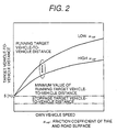
- Fig. 2 shows the relationship between the running target vehicle-to-vehicle distance, the stoppage target vehicle-to-vehicle distance and the own vehicle speed. From the minimum value (for example, 5[m]) of the running target vehicle-to-vehicle distance, the running target vehicle-to-vehicle distance is set in response to the own vehicle speed and the friction coefficient ⁇ HF of a road surface and a tire. Also, in case where it is impossible to measure or assume the friction coefficient ⁇ HF of the road surface and the tire, the running target vehicle-to-vehicle distance may be set so that when a wiper switch is OFF high ⁇ HF is provided and when the wiper switch is ON low ⁇ HF is provided.
- the stoppage target vehicle-to-vehicle distance is brought about regardless of the own vehicle speed.
- the setting value of the stoppage vehicle-to-vehicle distance can be set by the driver.
- the range within which the setting can be effected is the distance less than the minimum value the running target vehicle-to-vehicle distance.
- Fig. 3 is a first system configuration to which this invention is applied.
- a radar sensor 301 detects the distance between the proceeding vehicle and the own vehicle, and the relative speed.
- a transmission controller 305 controls an automatic transmission. Vehicle speed is transmitted to a vehicle-to-vehicle distance controller 302.
- the vehicle-to-vehicle distance controller 302 calculates the target speed from the vehicle-to-vehicle distance, the relative speed, the own vehicle speed and the target vehicle-to-vehicle distance, and further calculates target torque from its target speed and the own vehicle speed.
- the target torque is transmitted to an engine controller 303 and a brake controller 304. Also, if it is needed that a gear ratio should be changed, a gear change command is sent to a transmission controller 305.
- the opening angle of an electronic control throttle 306, the amount of fuel injected from a fuel injection valve 307 and the ignition timing of a ignition plug 308 are properly adjust to control engine timing.
- an oil pressure pump 309 and a proportional solenoid valve 310 are adjusted to the brake torque of a wheel.
- a valve 311 relays to a braking mechanism either one larger oil pressure of automatic braking oil pressure adjusted by the proportional solenoid valve and foot braking oil pressure adjusted by the driver through a master cylinder 316.
- a braking oil presser sensor 114 detects the braking oil pressure applied to the braking mechanism 313. The braking controller feedback-controls the proportional solenoid valve 310 with reference to the value of the braking oil pressure sensor 314.
- Fig. 4 is an example in which the start, stop is carried out by applying this invention. From above, vehicle-to-vehicle distance, the preceding vehicle speed, the own vehicle speed and the own vehicle acceleration are shown, and the horizontal axis represents time.
- the target vehicle-to-vehicle distance is set to the stoppage vehicle-to-vehicle distance when the preceding vehicle is stopping, and to the running target vehicle-to-vehicle distance when running.
- the stoppage vehicle-to-vehicle distance is set by the driver when the driver handles a switch for saturating the use of this invention.
- Step 501 it is judged whether the SET switch 319 (Fig. 3) is being ON. If ON, in next Step 502, it is judged whether the braking pedal 318 (Fig. 3) is working (ON state). If ON, in next Step 503, it is judged whether the own vehicle is stopping.
- Step 504 an announcement that the vehicle-to-vehicle distance control does not carried out and an announcement that the stoppage vehicle-to-vehicle distance cannot be set are made to the driver using an audio signal.
- the announcements may be made by a lump and/or character representation in addition to the audio.
- Step 505 it is judged whether the measured vehicle-to-vehicle distance is shorter than the minimum value of the running vehicle-to-vehicle distance. If longer, in Step 506 the stoppage target vehicle-to-vehicle distance is set to the minimum value of the running vehicle-to-vehicle distance.
- step 507 the stoppage target vehicle-to-vehicle distance is set to the measured vehicle-to-vehicle distance.
- Step 508 an announcement that the setting of the stoppage vehicle-to-vehicle distance was carried out is made to the driver.
- Step 509 the stoppage vehicle-to-vehicle distance which was set is newly displayed.
- Table 1 shows an example of the setting of the stoppage target vehicle-to-vehicle distance set in the processes in Fig. 5.
- Preceding Vehicle Speed Own Vehicle Speed Measured Vehicle-to-Vehicle Distance Minimum Value of Running Target Vehicle-to-Vehicle Distance Stoppage Vehicle-to-Vehicle Distance which was Set 1 0[m/s] 0[m/s] 0[m] 5[m] 3[m] 2 0[m/s] 0[m/s] 6[m] 5[m] 5[m] 3 2[m/s] 0[m/s] 3[m] 5[m] 3[m] 4 2[m/s] 0[m/s] 6[m] 5[m] 5[m] 5 0[m/s] 2[m/s] 3[m] 5[m] No Modification 6 0[m/s] 2[m/s] 6[m] 5[m] No Modification 6 0[m/s] 2[m/s
- the table shows 6 examples in connection with the preceding vehicle speed, the own vehicle speed and the vehicle-to-vehicle distance.
- the minimum value of the running target vehicle-to-vehicle distance is set to 5[m].
- the stoppage target vehicle-to-vehicle distance is set to the measured vehicle-to-vehicle distance at the time when the driver handled the SET switch the braking pedal while the minimum value of the running target vehicle-to-vehicle distance is taken as the maximum value.
- the own vehicle speed is 2[m/s] (the own vehicle is running)
- the stoppage target vehicle-to-vehicle distance is not changed.
- the minimum value of the running target vehicle-to-vehicle distance is set.
- the driver can set the stoppage target vehicle-to-vehicle distance certainly and visually.
- the stoppage target vehicle-to-vehicle distance is set to the measured vehicle-to-vehicle distance as shown in the processes in Fig. 5.
- the target vehicle-to-vehicle distance is changed from the stoppage target vehicle-to-vehicle distance to the minimum value of the running target vehicle-to-vehicle distance.
- the throttle opening command is always started at a constant period (the range from 10[ms] to 100[ms]), and is set through the processes shown in Fig. 6, Fig. 7 and Fig. 8.
- Fig. 6 shows processes in the vehicle-to-vehicle distance controller 302 in Fig. 3.
- Step 601 the own vehicle speed is acquired.
- Step 602 the relative speed Vr is acquired.
- Step 3 the target vehicle-to-vehicle distance Dr is set.
- the preceding vehicle speed can be measured as the sum of the own vehicle speed and the relative speed.
- the target vehicle-to-vehicle distance Dr is set to the stoppage vehicle-to-vehicle distance.
- the running target vehicle-to-vehicle distance is set in response to the own vehicle speed.
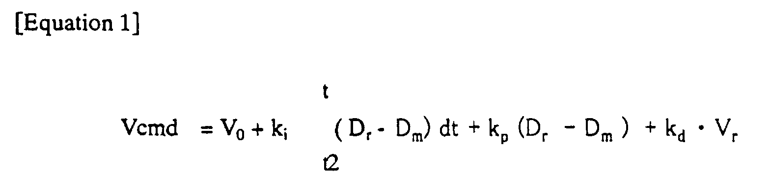
- the target Vcmd is set.
- the settings are effected using following Equation 1:
- Ki, Kp and Kd are control constants, which is set to predetermined values.
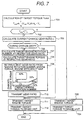
- Fig. 7 shows processes processed through the vehicle-to-vehicle distance controller 302 following the processes in Fig. 6.
- the target torque Tcmd is calculated from the target speed Vcmd and the own vehicle speed Vo, by using following Equation 2:
- Kj and Kq are control constants which are set predetermined values.
- Step 702 a predetermined torque Tth and a target torque Tcmd are compared. In case where the target torque is larger than the predetermined torque, processes in Step 705 and later are carried out, and the target torque is smaller, processes in Step 703 and later are carried out.
- Step 705 a current change gear ration is calculated on the basis of engine rotation number and wheel rotation number.
- Step 706 the judgment of "during speed change” is performed on the basis of the fact as to whether the calculated change gear ratio is the same as the predetermined change gear ration of a transmission installed in the vehicle. If not “during speed change", in Step 707, the target engine rotation number is calculated, by using the gear ratio of the transmission installed in the vehicle, in the case of the use of the respective gears.
- Step 708 the target engine torque is calculated in case where the respective gears were used.
- Step 709 engine heat efficiency in case where the respective gear ratio is used is retrieved from the map of the target engine rotation number, the target engine torque and the engine heat efficiency.
- the gear ratio, target engine rotation number and target engine torque giving the best engine heat efficiency are selected. For example, in Fig. 7, since the engine heat efficiency is 20% at the time of the first-speed gear ration and the engine heat efficiency is 30% at the time of the second-speed gear ration, the second-speed is selected.
- Step 710 the gear ratio and the target engine torque are transmitted to the transmission controller and the engine controller, respectively, as command values.
- Step 706 the "during speed change" is judged, the engine controller operates on the basis of the command of the transmission controller, and therefore the command from the vehicle-to-vehicle distance controller is not transmitted.
- Step 711 a command for releasing the automatic braking is transmitted to the brake controller.
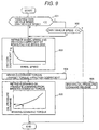
- Fig. 8 shows processes for transforming the target engine torque to the throttle opening command in the engine controller.
- the target engine torque is acquired.
- the engine rotation number is acquired.
- the throttle opening is retrieved from the map of the engine rotation number, the engine torque and the throttle opening, and it is made to the throttle opening command value.
- the electronic control throttle 306 in Fig. 3 is controlled. Further, in line with the filled air amount of the cylinder 320 which varies in response to the throttle opening, the amount of fuel injection and the timing of ignition are controlled to effectuate the target engine torque.
- Step 901 the comparison of the assumed own vehicle speed assumed from the time-series data of the vehicle speed with the own vehicle speed is performed, and if it is larger than a predetermined range C, the process in Step 902 is vehicleried out. In case where the difference between the assumed own vehicle speed and the own vehicle speed is large, there is the possibility that the wheel is locked. In case where it is small, the process in Step 903 is vehicleried out. In Step 902, the comparison of the own vehicle speed with a predetermined speed Vt, is vehicleried out, and if it is small, the process of Step 903 is performed.
- Step 903 a friction coefficient ⁇ B is retrieved from the relationship between the wheel speed of the own vehicle which has been measured in advance and the friction coefficient ⁇ B of a braking pad and a brake disk.
- torque for the braking command is calculated on the basis of the retrieved friction coefficient ⁇ B and the target torque Tcmd.
- Step 905 braking oil pressure command is retrieved and set on the basis of the relationship between preset torque for the braking command and braking oil pressure command. Then, on the basis of the braking oil pressure command, the proportional solenoid valve 310 in Fig.
- Step 902 in case where the own vehicle speed is larger than a predetermined speed Vt, the braking oil pressure command is made to zero to prevent the lock of the wheel.
- the valve 311 is coupled the brake master cylinder 314 which the driver handles, and in the case where the driver handles the brake, it is possible to decelerate the vehicle by apply the braking oil pressure to the braking mechanism 313 through the valve 311.
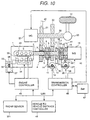
- Fig. 10 shows a configuration of a hybrid vehicle system according to the second embodiment of this invention.
- the output shaft 2 of an engine 1 comprises a low speed engine-side gear 4 having a mating gear 3, a high speed engine-side gear 6 having a mating gear 5, and a hub 7 and sleeve 8 for coupling directly the low speed engine-side gear 4 and the high speed engine-side gear 6 to the output shaft 2.
- a low speed engine-side gear 4 having a mating gear 3
- a high speed engine-side gear 6 having a mating gear 5
- a hub 7 and sleeve 8 for coupling directly the low speed engine-side gear 4 and the high speed engine-side gear 6 to the output shaft 2.
- the mating gears 3 and 5 and the hub 7 have the same grooves and on the inside of the sleeve 8 a groove (not shown) is formed which engages with the hub 7.
- a linear actuator consisting of a rack 11, a small gear 12 engaging with the rack and a stepping motor 13 is used.
- the periphery of the sleeve 8 is made free with respect to the rotational direction of the output shaft 2, and a lever 14 is installed which does not rotate with respect to the rotation of the sleeve 8.
- a clutch mechanism comprised of the hub 7, the sleeve 8, the mating gear 3 and the mating gear 5 is called as a dog clutch.
- This mechanism can transmit the energy of a power source such as the engine 1 to a tire 10 with high efficiency.
- the stepping motor (1) 13 can recognize the rotational angle by preset step number, and therefore it is possible to judge the moving position of the rack 11. Accordingly, it is possible to judge, at present, whether the low speed engine-side gear 4 is being used, whether the high speed engine-side gear 6 is being used or whether a neutral position is set.
- the above-mentioned judgment can be preformed by the combination of a sensor for detecting the position of the rack and a direct current motor.
- the above-mentioned clutch mechanism and linear actuator are used also to couple directly the output shaft 2 of the engine 1 and a generator 15.
- a gear 18 for detecting the rotational number Ne of the engine 1 is installed on the output shaft 2 .
- the gear 18 rotates with the output shaft 2 and has a mating gear 17.
- a gear 22 for detecting the rotation number Ng of the generator 15 is installed on the output shaft 16 .
- the gear 22 rotates with the output shaft 16 and has a hub 20 movable along a groove 19 in the axial direction of the output shaft 16 and a mating gear 21.
- a sleeve 23 is provided on the periphery of the hub 20.
- a linear actuator portion comprises a lever 25, a rack 26, a small gear 27 and a stepping motor (2) 28.
- a low speed motor-side gear 31 and a high speed motor-side gear 32 are mounted which engage with the low speed engine-side gear 4 and the high speed engine-side gear 6, respectively.
- the low speed motor-side gear 31 is used to detect the rotational number Nm of the motor-generator 29.
- a final deceleration gear 33 is mounted which enables the running only by the motor-generator 29.
- the target motor torque is converted to target current in the transmission controller, and in order to bring the target current into line with current flowing through the stator of the motor-generator 29, the applied voltage of the stator and the period are controlled and the output torque of the motor-generator 29 is effectuated.
- the target motor torque is negative, the applied voltage of the stator is released. Since the vehicle cannot stop abruptly, a configuration in which the tire rotates the motor-generator 29 is come up with.
- Fig. 11 is the flow of processes for anticipating the future speed of the preceding vehicle. This is activated at a period Tc.
- Step 1101 the preceding vehicle speed which was measured at the time of the last time activation is acquired.
- Step 1102 the future speed Veo(t-T)of the preceding vehicle which was calculated at the time of the last time activation is acquired.
- Step 1003 the presently measured preceding vehicle speed is acquired.
- Step 1104 the comparison of the preceding.
- Equation 3 1 2•T c (V p (t) - V ep (t - T c )
- either one of the running target vehicle-to-vehicle distance and the stoppage target vehicle-to-vehicle distance is selected.
- the control is made more quickly than that using the measured preceding vehicle speed, and therefore it is efficient at the time of the deceleration of the preceding vehicle especially. Also, at the time of the stoppage of the preceding vehicle, it is possible to switch the target vehicle-to-vehicle distance more quickly.
- the embodiment is applicable to a vehicle comprising detection means for detecting the vehicle-to-vehicle distance between the own vehicle and the preceding vehicle, an internal combustion engine or a motor, a transmission shaft for transmitting the rotation of the internal combustion engine or the motor to a wheel, modification means mounted on the internal combustion engine or the motor, the transmission shaft, or the wheel for modify its number of rotation, and control means receiving a signal from the detection means and outputting a control signal to the modification means for causing to run the own vehicle to follow the preceding, vehicle, and in case where the preceding vehicle stopped, said own vehicle once stops, and thereafter restarts the running, and stops at the vehicle-to-vehicle distance backward with respect to the preceding vehicle.
- detection means for detecting the vehicle-to-vehicle distance between the own vehicle and the preceding vehicle
- an internal combustion engine or a motor for transmitting the rotation of the internal combustion engine or the motor to a wheel
- modification means mounted on the internal combustion engine or the motor, the transmission shaft, or the wheel for modify its number
Landscapes
- Engineering & Computer Science (AREA)
- Mechanical Engineering (AREA)
- Transportation (AREA)
- Chemical & Material Sciences (AREA)
- Combustion & Propulsion (AREA)
- Automation & Control Theory (AREA)
- General Engineering & Computer Science (AREA)
- Controls For Constant Speed Travelling (AREA)
- Control Of Vehicle Engines Or Engines For Specific Uses (AREA)
- Control Of Driving Devices And Active Controlling Of Vehicle (AREA)
Abstract
Description
| Preceding Vehicle Speed | Own Vehicle Speed | Measured Vehicle-to-Vehicle Distance | Minimum Value of Running Target Vehicle-to-Vehicle Distance | Stoppage Vehicle-to-Vehicle Distance Which was Set | |
| 1 | 0[m/s] | 0[m/s] | 0[m] | 5[m] | 3[m] |
| 2 | 0[m/s] | 0[m/s] | 6[m] | 5[m] | 5[m] |
| 3 | 2[m/s] | 0[m/s] | 3[m] | 5[m] | 3[m] |
| 4 | 2[m/s] | 0[m/s] | 6[m] | 5[m] | 5[m] |
| 5 | 0[m/s] | 2[m/s] | 3[m] | 5[m] | No Modification |
| 6 | 0[m/s] | 2[m/s] | 6[m] | 5[m] | No Modification |
since the own vehicle speed is 2[m/s] (the own vehicle is running), the stoppage target vehicle-to-vehicle distance is not changed. At that time, in case where the stoppage target vehicle-to-vehicle distance is not being set (at the first time), the minimum value of the running target vehicle-to-vehicle distance is set. With the processes shown in Fig. 5, the driver can set the stoppage target vehicle-to-vehicle distance certainly and visually.

Claims (15)
- A vehicle running control device having:wherein said first running mode and said second running mode are switched on the basis of the speed of the preceding vehicle.a first running mode in which a distance between an own vehicle and a preceding vehicle is controlled on the basis of the relative speed difference between these two vehicles, anda second running mode in which the distance between the own vehicle and the preceding vehicle is controlled to a predetermined target value,
- A vehicle running controlling device according to claim 1, comprising means for anticipating a future speed of the preceding vehicle on the basis of present or past information.
- A vehicle running controlling device according to any one of claim 1 or 2, wherein said speed is a value within the range from the kilometer per hour of 0 to the kilometer per hour of 18.
- A vehicle running control device having:wherein, after the detection that the speed of the preceding vehicle became substantially zero was carried out, said first running mode is switched to said second running mode.a first running mode in which a distance between an own vehicle and a preceding vehicle is controlled on the basis of the relative speed difference between these two vehicles, anda second running mode in which the distance between the own vehicle and the preceding vehicle is controlled to a predetermined target value,
- A vehicle running controlling device according to any one of claim 1 or 4,
wherein said target value is set when both of the speed of the preceding vehicle and the speed of the own vehicle are substantially zero. - A vehicle running controlling device according to claim 5,
wherein, in case where the measured distance between the proceeding vehicle and the own vehicle is smaller than the pre-stored minimum value of the distance between said two vehicles at said first running mode, said measured distance is set as said target value. - A vehicle running controlling device according to claim 5,
wherein, in case where the measured distance between the proceeding vehicle and the own vehicle is larger than the pre-stored minimum value of the distance between said two vehicles at said first running mode, said minimum value is set as said target value. - A vehicle running controlling device according to any one of claim 1 or 4,
wherein after the accelerated speed of the own vehicle was made larger than the accelerated speed of the own vehicle at the time when the speed of the preceding vehicle became substantially zero, stoppage is carried out. - A vehicle running controlling device according to claim 5,
wherein said setting is input by the driver. - In a vehicle comprising:wherein said control means has a first running mode in which the distance between the own vehicle and said preceding vehicle is controlled on the basis of the detected relative speed, and a second running mode in which the detected vehicle-to-vehicle distance is controlled to a preset target value; andan internal combustion engine or a motor;a transmission shaft for transmitting the rotation of said internal combustion engine or said motor to a wheel;modification means installed in said internal combustion engine or said motor or said transmission shaft or said wheel, for modifying the number of rotation thereof;relative speed detection means for detecting the relative speed between the own vehicle and a preceding vehicle;vehicle-to-vehicle distance detection means for detecting the distance between the own vehicle and said preceding vehicle; andcontrol means receiving signals from said relative speed detection means and said vehicle-to-vehicle distance detection means, for outputting a control signal to said modification means;a vehicle running control device:
wherein said first running mode is switched to said second running mode on the basis of the speed of said preceding vehicle. - In a vehicle comprising:wherein said control means has a first running mode in which the distance between the own vehicle and said preceding vehicle is controlled on the basis of the detected relative speed, and a second running mode in which the detected vehicle-to-vehicle distance is controlled to a preset target value; andan internal combustion engine or a motor;a transmission shaft for transmitting the rotation of said internal combustion engine or said motor to a wheel;modification means installed in said internal combustion engine or said motor or said transmission shaft or said wheel, for modifying the number of rotation thereof;relative speed detection means for detecting the relative speed between the own vehicle and a preceding vehicle;vehicle-to-vehicle distance detection means for detecting the distance between the own vehicle and said preceding vehicle; andcontrol means receiving signals from said relative speed detection means and said vehicle-to-vehicle distance detection means, for outputting a control signal to said modification means;a vehicle running control device:
wherein, after the detection that the speed of the preceding vehicle became substantially zero was carried out, said first running mode is switched to said second running mode. - In a vehicle comprising:wherein, in case where said preceding vehicle stopped, the accelerated speed of the own vehicle is made lager than the accelerated speed of said own vehicle at the time when said preceding vehicle stopped, and thereafter stoppage is carried out with a distance between the vehicles at the back with respect to said preceding vehicle.detection means for detecting the distance between the own vehicle and a preceding vehicle;an internal combustion engine or a motor,a transmission shaft for transmitting the rotation of said internal combustion engine or said motor to a wheel;modification means installed in said internal combustion engine or said motor or said transmission shaft or said wheel, for modifying the number of rotation thereof; andcontrol means receiving a signal from said detection means, for supplying a control signal to said modification means and causing the own vehicle to run following said preceding vehicle;a vehicle running control device:
- A vehicle comprising+
detection means for detecting the distance between the own vehicle and a preceding vehicle;
an internal combustion engine or a motor;
a transmission shaft for transmitting the rotation of said internal combustion engine or said motor to a wheel;
modification means installed in said internal combustion engine or said motor or said transmission shaft or said wheel, for modifying the number of rotation thereof; and
control means receiving a signal from said detection means, for supplying a control signal to said modification means and causing the own vehicle to run following said preceding vehicle;
wherein the own vehicle continues its running even after said preceding vehicle stopped, and after the distance between said preceding vehicle and the own vehicle became smaller than a target value, stoppage is carried out with a distance between the vehicles at the back with respect to said preceding vehicle. - A vehicle comprising:wherein even where said preceding vehicle stopped, the own vehicle also stops and thereafter restarts the running and stoppage is carried out with a distance between the own vehicles at the back with respect to said preceding vehicle.detection means for detecting the distance between the own vehicle and a preceding vehicle;an internal combustion engine or a motor;a transmission shaft for transmitting the rotation of said internal combustion engine or said motor to a wheel;modification means installed in said internal combustion engine or said motor or said transmission shaft or said wheel, for modifying the number of rotation thereof; andcontrol means receiving a signal from said detection means, for supplying a control signal to said modification means and causing the own vehicle to run following said preceding vehicle;
- A vehicle according to any one of claim 1 through 14:
wherein said target value is a value from 0.5m to 5m..
Applications Claiming Priority (1)
| Application Number | Priority Date | Filing Date | Title |
|---|---|---|---|
| PCT/JP1999/002447 WO2000069665A1 (en) | 1999-05-12 | 1999-05-12 | Vehicle running control device and vehicle |
Publications (3)
| Publication Number | Publication Date |
|---|---|
| EP1193106A1 true EP1193106A1 (en) | 2002-04-03 |
| EP1193106A4 EP1193106A4 (en) | 2005-06-15 |
| EP1193106B1 EP1193106B1 (en) | 2008-09-03 |
Family
ID=14235652
Family Applications (1)
| Application Number | Title | Priority Date | Filing Date |
|---|---|---|---|
| EP99919537A Expired - Lifetime EP1193106B1 (en) | 1999-05-12 | 1999-05-12 | Vehicle running control device and vehicle |
Country Status (5)
| Country | Link |
|---|---|
| US (1) | US6622078B1 (en) |
| EP (1) | EP1193106B1 (en) |
| JP (1) | JP3937728B2 (en) |
| DE (1) | DE69939493D1 (en) |
| WO (1) | WO2000069665A1 (en) |
Cited By (4)
| Publication number | Priority date | Publication date | Assignee | Title |
|---|---|---|---|---|
| EP1437254A1 (en) * | 2003-01-09 | 2004-07-14 | Ford Global Technologies, Inc. | An adaptive cruise control system for a motor vehicle |
| WO2012072464A1 (en) * | 2010-11-30 | 2012-06-07 | Valeo Schalter Und Sensoren Gmbh | Method for operating a vehicle and driver assistance device |
| WO2015008060A3 (en) * | 2013-07-16 | 2015-04-16 | Bentley Motors Limited | Vehicle |
| WO2022063859A1 (en) * | 2020-09-22 | 2022-03-31 | Jaguar Land Rover Limited | Control of vehicle-to-vehicle separation |
Families Citing this family (12)
| Publication number | Priority date | Publication date | Assignee | Title |
|---|---|---|---|---|
| WO2001099081A1 (en) * | 2000-06-20 | 2001-12-27 | Hitachi, Ltd. | Vehicle control device |
| JP3431021B2 (en) * | 2001-05-24 | 2003-07-28 | 日産自動車株式会社 | Vehicle fuel cell system |
| US6998727B2 (en) * | 2003-03-10 | 2006-02-14 | The United States Of America As Represented By The Administrator Of The Environmental Protection Agency | Methods of operating a parallel hybrid vehicle having an internal combustion engine and a secondary power source |
| US6876098B1 (en) * | 2003-09-25 | 2005-04-05 | The United States Of America As Represented By The Administrator Of The Environmental Protection Agency | Methods of operating a series hybrid vehicle |
| US7627413B2 (en) * | 2005-03-31 | 2009-12-01 | Nissan Technical Center North America, Inc. | System and methods utilizing slope of target speed for cooperative speed for cooperative speed control system |
| JP4674491B2 (en) * | 2005-05-20 | 2011-04-20 | 日産自動車株式会社 | Preceding vehicle tracking control device |
| JP4973573B2 (en) * | 2008-03-28 | 2012-07-11 | 日産自動車株式会社 | Inter-vehicle distance control device and inter-vehicle distance control method |
| US20100020170A1 (en) * | 2008-07-24 | 2010-01-28 | Higgins-Luthman Michael J | Vehicle Imaging System |
| JP5332993B2 (en) * | 2009-07-15 | 2013-11-06 | トヨタ自動車株式会社 | Travel plan generator |
| GB2508668A (en) * | 2012-12-10 | 2014-06-11 | Jaguar Land Rover Ltd | Adaptive cruise control (ACC) means for a host vehicle having regenerative and non-regenerative braking means |
| JP7255113B2 (en) * | 2018-09-13 | 2023-04-11 | いすゞ自動車株式会社 | Vehicle control device and vehicle control method |
| KR102895469B1 (en) * | 2020-12-11 | 2025-12-05 | 현대자동차주식회사 | Apparatus and method for contorlling hybrid vehicle |
Family Cites Families (17)
| Publication number | Priority date | Publication date | Assignee | Title |
|---|---|---|---|---|
| JPH0614400B2 (en) * | 1983-10-26 | 1994-02-23 | 本田技研工業株式会社 | Inter-vehicle distance warning device |
| JPH0261799A (en) * | 1988-08-26 | 1990-03-01 | Fujitsu Ten Ltd | Device for controlling distance between cars |
| JPH02241938A (en) * | 1989-03-14 | 1990-09-26 | Mazda Motor Corp | Controller for vehicle |
| JPH0412144A (en) * | 1990-04-28 | 1992-01-16 | Aisin Seiki Co Ltd | Vehicle speed control device |
| JPH04113500A (en) * | 1990-09-03 | 1992-04-14 | Mitsubishi Electric Corp | Automatic stoppage/departure device for vehicle |
| US5173859A (en) * | 1990-11-05 | 1992-12-22 | General Motors Corporation | Automatic vehicle deceleration |
| JPH0818233B2 (en) | 1992-07-21 | 1996-02-28 | 新日本製鐵株式会社 | Grinding machine for strip metal |
| EP0841648B1 (en) * | 1992-09-30 | 2004-06-02 | Hitachi, Ltd. | Vehicle driving support system and vehicle therewith |
| JPH06111199A (en) * | 1992-09-30 | 1994-04-22 | Hitachi Ltd | Vehicle running mode change device |
| DE4418085C2 (en) * | 1993-05-21 | 1999-09-09 | Toyota Motor Co Ltd | Safety device for a vehicle |
| JP3208983B2 (en) | 1993-09-24 | 2001-09-17 | トヨタ自動車株式会社 | Inter-vehicle distance control device |
| JP3127083B2 (en) * | 1994-07-21 | 2001-01-22 | ダイハツ工業株式会社 | Rear-end collision judgment method in rear-end collision prevention system |
| JPH08169251A (en) * | 1994-12-15 | 1996-07-02 | Nissan Motor Co Ltd | Vehicle tracking control device |
| FR2732651B1 (en) * | 1995-04-07 | 1997-05-09 | Renault | METHOD AND DEVICE FOR REGULATING THE LONGITUDINAL ACCELERATION OF A ROAD VEHICLE |
| JP3374321B2 (en) * | 1995-11-30 | 2003-02-04 | トヨタ自動車株式会社 | Constant-speed driving device, automobile constant-speed traveling device, and control method for power output device |
| JP3395575B2 (en) * | 1997-06-10 | 2003-04-14 | 日産自動車株式会社 | Vehicle follow-up control system |
| US6233515B1 (en) * | 1998-12-07 | 2001-05-15 | Jaguar Car, Limited | Adaptive vehicle cruise control system and methodology |
-
1999
- 1999-05-12 US US09/959,943 patent/US6622078B1/en not_active Expired - Fee Related
- 1999-05-12 WO PCT/JP1999/002447 patent/WO2000069665A1/en not_active Ceased
- 1999-05-12 JP JP2000618104A patent/JP3937728B2/en not_active Expired - Fee Related
- 1999-05-12 EP EP99919537A patent/EP1193106B1/en not_active Expired - Lifetime
- 1999-05-12 DE DE69939493T patent/DE69939493D1/en not_active Expired - Lifetime
Cited By (10)
| Publication number | Priority date | Publication date | Assignee | Title |
|---|---|---|---|---|
| EP1437254A1 (en) * | 2003-01-09 | 2004-07-14 | Ford Global Technologies, Inc. | An adaptive cruise control system for a motor vehicle |
| WO2012072464A1 (en) * | 2010-11-30 | 2012-06-07 | Valeo Schalter Und Sensoren Gmbh | Method for operating a vehicle and driver assistance device |
| CN103370251A (en) * | 2010-11-30 | 2013-10-23 | 法雷奥开关和传感器有限责任公司 | Method for operating a vehicle and driver assistance device |
| US9381897B2 (en) | 2010-11-30 | 2016-07-05 | Valeo Schalter Und Sensoren Gmbh | Method for operating a vehicle and driver assistance device |
| WO2015008060A3 (en) * | 2013-07-16 | 2015-04-16 | Bentley Motors Limited | Vehicle |
| CN105473395A (en) * | 2013-07-16 | 2016-04-06 | 宾利汽车有限公司 | Vehicle |
| CN105473395B (en) * | 2013-07-16 | 2018-01-16 | 宾利汽车有限公司 | vehicle |
| US9944198B2 (en) | 2013-07-16 | 2018-04-17 | Bentley Motors Limited | Vehicle |
| WO2022063859A1 (en) * | 2020-09-22 | 2022-03-31 | Jaguar Land Rover Limited | Control of vehicle-to-vehicle separation |
| US12280780B2 (en) | 2020-09-22 | 2025-04-22 | Jaguar Land Rover Limited | Control of vehicle-to-vehicle separation |
Also Published As
| Publication number | Publication date |
|---|---|
| EP1193106B1 (en) | 2008-09-03 |
| WO2000069665A1 (en) | 2000-11-23 |
| EP1193106A4 (en) | 2005-06-15 |
| JP3937728B2 (en) | 2007-06-27 |
| DE69939493D1 (en) | 2008-10-16 |
| US6622078B1 (en) | 2003-09-16 |
Similar Documents
| Publication | Publication Date | Title |
|---|---|---|
| EP1193106A1 (en) | Vehicle running control device and vehicle | |
| JP3687639B2 (en) | Rotation direction discrimination device for electric motor drive wheel | |
| EP3575130B1 (en) | Vehicle control system and method of controlling the same, and braking device | |
| US7585250B2 (en) | Method for operating a motor vehicle | |
| US6330508B1 (en) | Preceding vehicle following control system | |
| KR100310605B1 (en) | Clutch reengagement control | |
| EP3608191B1 (en) | Vehicle control method and vehicle control device | |
| US9327705B2 (en) | Method and device for steering a vehicle toward an object during a parking operation | |
| GB2310731A (en) | Control of the approach of a vehicle to an obstruction | |
| KR20010083907A (en) | Hill Holder Device For A Motor Vehicle | |
| US6594572B1 (en) | Device for authorizing an unrestricted operating mode of a vehicle control device in the event of a failure of the ignition signal | |
| JP2008032231A (en) | Method and device for controlling torque transmitting system | |
| EP3608186B1 (en) | Control method for hybrid vehicles | |
| KR20000068977A (en) | Device and Method for Adjusting the Transmission Ratio of a CVT | |
| EP1609662B1 (en) | Drive control apparatus and method for vehicles | |
| JP2006504053A (en) | Method for controlling a drive transmission system including a clutch | |
| JP2006123642A (en) | Hybrid vehicle drive device, control method thereof and control device | |
| JPWO2000069665A1 (en) | Vehicle driving control device and vehicle | |
| US6272416B1 (en) | Vehicle drive force control device | |
| US20060128520A1 (en) | Vehicle driving force control system | |
| US20230331228A1 (en) | Driving assistance method and driving assistance device | |
| JP3885347B2 (en) | Vehicle travel control device | |
| JP2000205395A (en) | Neutral control device for automatic transmission | |
| JP3775424B2 (en) | Electric motor drive wheel drive control device | |
| JP3791525B2 (en) | Four-wheel drive vehicle |
Legal Events
| Date | Code | Title | Description |
|---|---|---|---|
| PUAI | Public reference made under article 153(3) epc to a published international application that has entered the european phase |
Free format text: ORIGINAL CODE: 0009012 |
|
| 17P | Request for examination filed |
Effective date: 20011130 |
|
| AK | Designated contracting states |
Kind code of ref document: A1 Designated state(s): DE FR GB IT |
|
| A4 | Supplementary search report drawn up and despatched |
Effective date: 20050428 |
|
| 17Q | First examination report despatched |
Effective date: 20060704 |
|
| GRAP | Despatch of communication of intention to grant a patent |
Free format text: ORIGINAL CODE: EPIDOSNIGR1 |
|
| GRAS | Grant fee paid |
Free format text: ORIGINAL CODE: EPIDOSNIGR3 |
|
| GRAA | (expected) grant |
Free format text: ORIGINAL CODE: 0009210 |
|
| RAP1 | Party data changed (applicant data changed or rights of an application transferred) |
Owner name: HITACHI, LTD. |
|
| AK | Designated contracting states |
Kind code of ref document: B1 Designated state(s): DE FR GB IT |
|
| REG | Reference to a national code |
Ref country code: GB Ref legal event code: FG4D |
|
| REF | Corresponds to: |
Ref document number: 69939493 Country of ref document: DE Date of ref document: 20081016 Kind code of ref document: P |
|
| PLBE | No opposition filed within time limit |
Free format text: ORIGINAL CODE: 0009261 |
|
| STAA | Information on the status of an ep patent application or granted ep patent |
Free format text: STATUS: NO OPPOSITION FILED WITHIN TIME LIMIT |
|
| 26N | No opposition filed |
Effective date: 20090604 |
|
| PGFP | Annual fee paid to national office [announced via postgrant information from national office to epo] |
Ref country code: GB Payment date: 20130508 Year of fee payment: 15 |
|
| PGFP | Annual fee paid to national office [announced via postgrant information from national office to epo] |
Ref country code: IT Payment date: 20130522 Year of fee payment: 15 |
|
| GBPC | Gb: european patent ceased through non-payment of renewal fee |
Effective date: 20140512 |
|
| PG25 | Lapsed in a contracting state [announced via postgrant information from national office to epo] |
Ref country code: IT Free format text: LAPSE BECAUSE OF NON-PAYMENT OF DUE FEES Effective date: 20140512 |
|
| PG25 | Lapsed in a contracting state [announced via postgrant information from national office to epo] |
Ref country code: GB Free format text: LAPSE BECAUSE OF NON-PAYMENT OF DUE FEES Effective date: 20140512 |
|
| REG | Reference to a national code |
Ref country code: FR Ref legal event code: PLFP Year of fee payment: 18 |
|
| PGFP | Annual fee paid to national office [announced via postgrant information from national office to epo] |
Ref country code: DE Payment date: 20160504 Year of fee payment: 18 |
|
| PGFP | Annual fee paid to national office [announced via postgrant information from national office to epo] |
Ref country code: FR Payment date: 20160412 Year of fee payment: 18 |
|
| REG | Reference to a national code |
Ref country code: DE Ref legal event code: R119 Ref document number: 69939493 Country of ref document: DE |
|
| REG | Reference to a national code |
Ref country code: FR Ref legal event code: ST Effective date: 20180131 |
|
| PG25 | Lapsed in a contracting state [announced via postgrant information from national office to epo] |
Ref country code: DE Free format text: LAPSE BECAUSE OF NON-PAYMENT OF DUE FEES Effective date: 20171201 |
|
| PG25 | Lapsed in a contracting state [announced via postgrant information from national office to epo] |
Ref country code: FR Free format text: LAPSE BECAUSE OF NON-PAYMENT OF DUE FEES Effective date: 20170531 |