EP1192481B1 - Connection system for connecting equipment to underwater cables - Google Patents
Connection system for connecting equipment to underwater cables Download PDFInfo
- Publication number
- EP1192481B1 EP1192481B1 EP00951064A EP00951064A EP1192481B1 EP 1192481 B1 EP1192481 B1 EP 1192481B1 EP 00951064 A EP00951064 A EP 00951064A EP 00951064 A EP00951064 A EP 00951064A EP 1192481 B1 EP1192481 B1 EP 1192481B1
- Authority
- EP
- European Patent Office
- Prior art keywords
- cuff
- cable
- gap
- race
- inner collar
- Prior art date
- Legal status (The legal status is an assumption and is not a legal conclusion. Google has not performed a legal analysis and makes no representation as to the accuracy of the status listed.)
- Expired - Lifetime
Links
- 238000010276 construction Methods 0.000 claims description 3
- 230000007246 mechanism Effects 0.000 description 7
- 238000000034 method Methods 0.000 description 7
- 239000013535 sea water Substances 0.000 description 5
- 229910052751 metal Inorganic materials 0.000 description 4
- 239000002184 metal Substances 0.000 description 4
- 150000002739 metals Chemical class 0.000 description 4
- 239000004033 plastic Substances 0.000 description 3
- 229920003023 plastic Polymers 0.000 description 3
- XLYOFNOQVPJJNP-UHFFFAOYSA-N water Substances O XLYOFNOQVPJJNP-UHFFFAOYSA-N 0.000 description 3
- 229910052782 aluminium Inorganic materials 0.000 description 2
- XAGFODPZIPBFFR-UHFFFAOYSA-N aluminium Chemical compound [Al] XAGFODPZIPBFFR-UHFFFAOYSA-N 0.000 description 2
- 230000007774 longterm Effects 0.000 description 2
- 239000000463 material Substances 0.000 description 2
- 238000011084 recovery Methods 0.000 description 2
- 230000000717 retained effect Effects 0.000 description 2
- 125000006850 spacer group Chemical group 0.000 description 2
- 239000004677 Nylon Substances 0.000 description 1
- 239000004698 Polyethylene Substances 0.000 description 1
- RTAQQCXQSZGOHL-UHFFFAOYSA-N Titanium Chemical compound [Ti] RTAQQCXQSZGOHL-UHFFFAOYSA-N 0.000 description 1
- 230000001133 acceleration Effects 0.000 description 1
- DHKHKXVYLBGOIT-UHFFFAOYSA-N acetaldehyde Diethyl Acetal Natural products CCOC(C)OCC DHKHKXVYLBGOIT-UHFFFAOYSA-N 0.000 description 1
- 125000002777 acetyl group Chemical class [H]C([H])([H])C(*)=O 0.000 description 1
- 230000004913 activation Effects 0.000 description 1
- 239000000853 adhesive Substances 0.000 description 1
- 230000001070 adhesive effect Effects 0.000 description 1
- 238000003491 array Methods 0.000 description 1
- 238000006243 chemical reaction Methods 0.000 description 1
- 238000006073 displacement reaction Methods 0.000 description 1
- 238000005516 engineering process Methods 0.000 description 1
- 239000007788 liquid Substances 0.000 description 1
- 238000005259 measurement Methods 0.000 description 1
- 229920001778 nylon Polymers 0.000 description 1
- -1 polyethylene Polymers 0.000 description 1
- 229920000573 polyethylene Polymers 0.000 description 1
- 230000008569 process Effects 0.000 description 1
- 238000005096 rolling process Methods 0.000 description 1
- 150000003839 salts Chemical class 0.000 description 1
- 239000010936 titanium Substances 0.000 description 1
- 229910052719 titanium Inorganic materials 0.000 description 1
Images
Classifications
-
- B—PERFORMING OPERATIONS; TRANSPORTING
- B63—SHIPS OR OTHER WATERBORNE VESSELS; RELATED EQUIPMENT
- B63B—SHIPS OR OTHER WATERBORNE VESSELS; EQUIPMENT FOR SHIPPING
- B63B21/00—Tying-up; Shifting, towing, or pushing equipment; Anchoring
- B63B21/56—Towing or pushing equipment
- B63B21/66—Equipment specially adapted for towing underwater objects or vessels, e.g. fairings for tow-cables
- B63B21/663—Fairings
-
- F—MECHANICAL ENGINEERING; LIGHTING; HEATING; WEAPONS; BLASTING
- F16—ENGINEERING ELEMENTS AND UNITS; GENERAL MEASURES FOR PRODUCING AND MAINTAINING EFFECTIVE FUNCTIONING OF MACHINES OR INSTALLATIONS; THERMAL INSULATION IN GENERAL
- F16L—PIPES; JOINTS OR FITTINGS FOR PIPES; SUPPORTS FOR PIPES, CABLES OR PROTECTIVE TUBING; MEANS FOR THERMAL INSULATION IN GENERAL
- F16L1/00—Laying or reclaiming pipes; Repairing or joining pipes on or under water
- F16L1/12—Laying or reclaiming pipes on or under water
- F16L1/16—Laying or reclaiming pipes on or under water on the bottom
-
- G—PHYSICS
- G01—MEASURING; TESTING
- G01V—GEOPHYSICS; GRAVITATIONAL MEASUREMENTS; DETECTING MASSES OR OBJECTS; TAGS
- G01V1/00—Seismology; Seismic or acoustic prospecting or detecting
- G01V1/16—Receiving elements for seismic signals; Arrangements or adaptations of receiving elements
- G01V1/20—Arrangements of receiving elements, e.g. geophone pattern
- G01V1/201—Constructional details of seismic cables, e.g. streamers
-
- G—PHYSICS
- G01—MEASURING; TESTING
- G01V—GEOPHYSICS; GRAVITATIONAL MEASUREMENTS; DETECTING MASSES OR OBJECTS; TAGS
- G01V1/00—Seismology; Seismic or acoustic prospecting or detecting
- G01V1/38—Seismology; Seismic or acoustic prospecting or detecting specially adapted for water-covered areas
- G01V1/3817—Positioning of seismic devices
Definitions
- This invention relates to marine seismic prospecting and, more particularly, to a connection system for attaching equipment to and detaching equipment from marine seismic cables.
- a marine seismic streamer is a cable, typically several thousand meters long, that contains arrays of hydrophones and associated electronic equipment along its length.
- One purpose of the streamer is to position the hydrophone array at a known depth and orientation relative to a towing vessel in a survey area.
- Externally mounted equipment such as depth controllers, called “birds,” emergency recovery pods, and acoustic pods, performs the functions of positioning and controlling the cable.
- Individual units of these kinds of external equipment are attached to the streamer at various positions along its length. All of these external units should be both attached to and removed from the cable as quickly and reliably as possible. Operational expenses of seismic vessels require rapid attachment and detachment of these external units. Because these external units typically cost thousands of dollars, they demand the highest degree of reliability from any attachment scheme. Cable attachment failures caused by connector failures or by cable accidents result in a significant financial loss both in time and in expensive equipment.
- a thick cross section (typically of aluminum) is required to safely imbed a conventional latching mechanism within the collar.
- Such a large cross section creates hydrodynamic noise and lateral accelerations on the seismic cable as it is towed through the water. These undesirable characteristics corrupt the sensitive measurement of seismic acoustic signals by the hydrophones.
- the connection system includes a cuff attached to a piece of equipment to be connected to the streamer cable at a known location.
- the C-shaped cylindrical cuff has a circular inner surface interrupted by a gap.
- a throat is formed by the gap in the cuff extending the length of the cuff.
- the spacing between the ends of the C across the throat defines the width of the gap.
- the width of the gap is slightly larger than the diameter of the streamer cable so that the cuff can slip onto the cable.
- An inner collar having a race is affixed to the cable at a known location. The diameter of the race is greater than the width of the gap formed by the cuff's throat.
- the inner surface of the cuff can be slid into position on the race of the inner collar. Because the diameter of the race exceeds the width of the gap of the throat, the cuff and the attached equipment cannot disconnect radially from the inner collar. Structural elements on the collar further prevent longitudinal displacement of the cuff along the inner collar. In this way, equipment is connected to the cable at a known location.
- the inner collar has a circumferential groove that admits a retractable pin extending from the external unit through an aperture in the cuff.
- the groove constrains the pin and prevents longitudinal movement of the external unit along the cable and off the inner collar.
- a single operator can remove the unit with the cuff from the inner collar by manually retracting the pin and sliding the cuff longitudinally off the inner collar and then radially off the cable.
- the inner collar has a raised circumferential shoulder just aft of the race to act as a precise longitudinal stop for the cuff. Forward motion of the cable through the water will hold the cuff against the shoulder.
- the cuff itself is of unitary construction with no moving parts.
- connection system includes a cuff having no moving parts and no dissimilar metals in contact to provide a connector that is significantly more reliable, even after long exposure to seawater.
- the connection system does not require two operators as do conventional systems. One operator suffices because the connection system requires no activation of a latch for a secure attachment.
- FIGS. 1 - 4 One example of a system embodying features of the invention for connecting external units to an underwater cable is shown in FIGS. 1 - 4 .
- a key component of the system which achieves a reliable, mechanism-free, connection to the seismic cable, is a C-shaped cylindrical ring, or cuff 10, serving as an outer collar.
- the cuff has an opening, or throat 12, formed by a gap in the cuff along the length of the cuff between the ends of the C.
- the width of the gap between the ends of the C across the throat is slightly larger than the diameter 14 of an underwater seismic cable 16.
- the cuff is preferably of unitary construction, i.e., no dissimilar metals or moving parts, fabricated from a material that will survive long term exposure to seawater and can withstand extensive mechanical loads.
- Each external unit 18, such as a cable-leveling bird as depicted in FIGS. 2 and 4 , an acoustic transmitter, receiver, or transceiver, a cable recovery device, or a float tube, to be connected to the cable typically has two attach points requiring two cuffs. (Of course, external units with a single cuff are also possible.)
- the cuffs are attached to the external units, for example, by attachment means using conventional external device hardware 20 as shown in the cutaway portion of FIG.
- two keyways 22 machined 180° apart around the circumference of the cuff accept a dovetail pin 24 extending from the external unit through an outer surface 27 of the cuff.
- the keyway has a circular opening 28 at one end to accept the head of the dovetail pin and a narrower slotted portion 30 extending from the circular opening to the other end of the keyway.
- the dovetail pin acts as a self-centering guide and swivel.
- Two keyways are provided to enable the mounting of two external units, such as a bird and a float tube, per connection location on a seismic cable.
- the throat is preferably positioned about midway between the two keyways so that the throat assumes an orientation on the cable not facing upward. The important point is that the throat should not be positioned on the cuff diametrically opposite an attached external unit. In other words, the throat should be spaced circumferentially around the cuff less than 180° from the attached external unit.
- an inner collar 32 is semi-permanently clamped around the cable 14 and establishes a longitudinal mounting position along the cable's length and forms the inner bearing race 34 for the cuff.
- the inner collar consists of two symmetrical halves 36, which are screwed together around the cable with screws or bolts 38 typically on top or in front of a cable spacer 40 located within the cable. Screw holes 42 on one side of the collar halves admit the screw heads, which thread into threaded holes 44 on the other side of the collar halves.
- Structural elements such as a pair of raised circumferential ribs 46, are included along the interior surface 48, which can be sized differently to match different seismic cables.
- the elements prevent longitudinal movement of the collar along the cable and, therefore, of an attached external unit.
- the ribs are spaced to just span the fixed cable spacer, which holds the clamped inner race in place.
- a beveled surface 50 at the fore end of the inner collar facilitates self-centering of the cuff.
- a shoulder 52 at the aft end prevents longitudinal translation of the external unit once installed.
- a circumferencial groove 54 accepts a conventional retractable pin 56 extending from the external unit.
- the spring-biased, self-activating pin allows the external unit with attached cuff to snap in place in the race and further prevents forward translation of the external unit along the cable.
- the inner collar 32 is preferably fabricated from a plastic that can withstand harsh mechanical and seawater exposure. For low friction and wear, an engineering grade plastic, such as acetal, nylon, and polyethylene, is preferred.
- the outer diameter 58 of the inner race 34 is slightly larger than the diameter 16 of the seismic cable.
- the inside diameter 60 of the cuff is slightly larger in diameter than the inner race.
- the width of the gap at the throat 12 of the cuff is slightly larger than the cable diameter, but less than the diameter of the inner race.
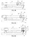
- FIGS. 4A - 4D A method for attaching an external unit to a streamer cable is shown in FIGS. 4A - 4D .
- an external device 18, retained to the cuff 10 by the dovetail pin 24, is installed by positioning each external cuff in front of and to the side of the inner races ( FIGS. 4A and 4B ).
- a radial motion perpendicular to the cable, as indicated by arrow 62, is required to slip the cuff and its throat over the cable to suspend the external unit from the cable.
- the cable temporarily supports the unit, unlike existing methods where an operator supports the device.
- a secondary longitudinal motion, indicated by arrow 64, along the length of the cable Fig.
- the retractable pin is first lowered out of the groove by downward pressure on a stub 66 extending out perpendicularly from the pin through a vertical slot 68 in the external device. The remainder of the detachment process is just the reverse order of the attachment procedure.
- the invention provides, among other advantages: a marine cable connection having no moving parts, which is more reliable than prior art connections; a marine cable connection that performs the same whether brand new or aged as a result of long term exposure to seawater; a marine cable connection that requires fewer operators to safely operate; a marine cable connection with a lower hydrodynamic noise profile because of the lack of a salient attachment mechanism; a marine cable connection that can readily be adapted to both existing seismic cables as well as new technology cables; a marine cable connection that is lighter and simpler than existing connectors; a marine cable connection that consists of an inner race and an outer collar engaged by means of geometrical features rather than a mechanism; and a marine cable connection that is significantly quicker to operate than prior art connectors.
- the invention has been described in detail with reference to a preferred version, other versions are possible.
- the rear inner race could have, but need not have, a circumferential groove and a cooperating retractable pin or a shoulder acting as a longitudinal stop.
- the gap forming the throat could be of constant width, as shown in the drawings, or could alternatively be narrower at one end than at the other.
- the cuff could have only a single keyway if attachment of two external units at a common location is not required. Instead of attaching to an external unit by means of a dovetail pin retained in a keyway, other attachment means are possible.
- the cuff could be semi-permanently fastened to the external unit by screws or other fasteners or permanently attached by adhesives or formed as an integral part of the external unit.
- the method of attachment can be manually performed as described or performed by an automated device handling system.
- a collar encircling the cable other connection structures could be used on the cable.
- a rigid structure inside the jacket of a liquid-filled cable causing a bulge in the cable could be received by the cuff or an in-line body, inserted between fore and aft cable sections, could engage a cuff.
- the invention also has application on untowed sea-bottom-deployed cables to which similar external units are attached. Therefore, the scope of the claims is not limited to the description of the preferred version.
Landscapes
- Engineering & Computer Science (AREA)
- Life Sciences & Earth Sciences (AREA)
- Physics & Mathematics (AREA)
- Geology (AREA)
- General Life Sciences & Earth Sciences (AREA)
- General Engineering & Computer Science (AREA)
- Mechanical Engineering (AREA)
- Geophysics (AREA)
- Acoustics & Sound (AREA)
- Environmental & Geological Engineering (AREA)
- General Physics & Mathematics (AREA)
- Remote Sensing (AREA)
- Ocean & Marine Engineering (AREA)
- Chemical & Material Sciences (AREA)
- Combustion & Propulsion (AREA)
- Oceanography (AREA)
- Laying Of Electric Cables Or Lines Outside (AREA)
- Geophysics And Detection Of Objects (AREA)
- Cable Accessories (AREA)
- Quick-Acting Or Multi-Walled Pipe Joints (AREA)
- Processing Of Terminals (AREA)
- Connector Housings Or Holding Contact Members (AREA)
Abstract
Description
- This invention relates to marine seismic prospecting and, more particularly, to a connection system for attaching equipment to and detaching equipment from marine seismic cables.
- A marine seismic streamer is a cable, typically several thousand meters long, that contains arrays of hydrophones and associated electronic equipment along its length. One purpose of the streamer is to position the hydrophone array at a known depth and orientation relative to a towing vessel in a survey area. Externally mounted equipment, such as depth controllers, called "birds," emergency recovery pods, and acoustic pods, performs the functions of positioning and controlling the cable. Individual units of these kinds of external equipment are attached to the streamer at various positions along its length. All of these external units should be both attached to and removed from the cable as quickly and reliably as possible. Operational expenses of seismic vessels require rapid attachment and detachment of these external units. Because these external units typically cost thousands of dollars, they demand the highest degree of reliability from any attachment scheme. Cable attachment failures caused by connector failures or by cable accidents result in a significant financial loss both in time and in expensive equipment.
- Today's typical cable attachment solutions consist of a collar arrangement that relies on a hinge and latch mechanism for operation. Examples of these mechanisms are described in
U.S. Patent 5,507,243 , "Connector For Underwater Cables," April 16, 1996, to Oneil J. Williams et al. and inU.S. Patent 5,709,497 , " Latching Device," January 20, 1998, to David W. Zoch et al. External units attached to the collars are clamped around races on the cable as the cable is payed out from the back deck of a survey vessel. The races allow the cable to rotate inside the collars while the external units do not rotate as they are towed along. Conventional connector schemes usually require one operator to position and hold the awkward external unit in place while a second operator secures the manual latching collars to the cable, often while trying to maintain balance on a rolling survey vessel. Requiring two operators significantly increases the cost of operation. - These conventional mechanisms also incorporate springs or pins having dissimilar metals in contact with the collar. Dissimilar metals in contact in seawater corrode because of galvanic reactions. While conventional hinge-and-latch collars offer quick attachment and removal when new, exposure to salt water degrades their performance and can eventually lead to their complete failure. A failed collar can result in the loss of an external electronic unit or a jammed connector on the seismic cable, which costs time in removing external devices as the cable is reeled in.
- A thick cross section (typically of aluminum) is required to safely imbed a conventional latching mechanism within the collar. Such a large cross section creates hydrodynamic noise and lateral accelerations on the seismic cable as it is towed through the water. These undesirable characteristics corrupt the sensitive measurement of seismic acoustic signals by the hydrophones.
- Clearly there is a need for an apparatus and a method for avoiding these serious shortcomings that significantly add to the cost of a seismic survey at sea.
- This need is satisfied and other shortcomings are overcome by an innovative cable connection system having features of the invention as set forth in claim 1. The connection system includes a cuff attached to a piece of equipment to be connected to the streamer cable at a known location. The C-shaped cylindrical cuff has a circular inner surface interrupted by a gap. A throat is formed by the gap in the cuff extending the length of the cuff. The spacing between the ends of the C across the throat defines the width of the gap. The width of the gap is slightly larger than the diameter of the streamer cable so that the cuff can slip onto the cable. An inner collar having a race is affixed to the cable at a known location. The diameter of the race is greater than the width of the gap formed by the cuff's throat. The inner surface of the cuff can be slid into position on the race of the inner collar. Because the diameter of the race exceeds the width of the gap of the throat, the cuff and the attached equipment cannot disconnect radially from the inner collar. Structural elements on the collar further prevent longitudinal displacement of the cuff along the inner collar. In this way, equipment is connected to the cable at a known location.
- In a preferred version of the system, the inner collar has a circumferential groove that admits a retractable pin extending from the external unit through an aperture in the cuff. The groove constrains the pin and prevents longitudinal movement of the external unit along the cable and off the inner collar. A single operator can remove the unit with the cuff from the inner collar by manually retracting the pin and sliding the cuff longitudinally off the inner collar and then radially off the cable. In an alternative version, the inner collar has a raised circumferential shoulder just aft of the race to act as a precise longitudinal stop for the cuff. Forward motion of the cable through the water will hold the cuff against the shoulder. Preferably, the cuff itself is of unitary construction with no moving parts.
- Thus, the novel connection system includes a cuff having no moving parts and no dissimilar metals in contact to provide a connector that is significantly more reliable, even after long exposure to seawater. The connection system does not require two operators as do conventional systems. One operator suffices because the connection system requires no activation of a latch for a secure attachment.
- These and other features, aspects, and advantages of the invention are better understood by referring to the following description, appended claims, and accompanying drawings in which:
-
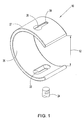
FIG. 1 is a perspective view of one version of a connector for use in a system for connecting devices to an underwater cable embodying features of the invention; -
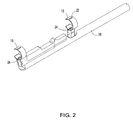
FIG. 2 is a perspective view of two connectors as inFIG. 1 shown attached to an external unit, in this example, a cable-leveling bird; -
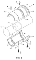
FIG. 3 is an exploded perspective view of an inner collar showing its attachment to a section of an underwater cable; and -
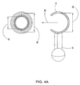
FIGS. 4A - 4D are front (FIG. 4A ) and side elevation (FIGS. 4B - 4D ) views of a section of an underwater cable showing a system according to the invention and an associated procedure for attaching an external unit to the cable at a known location. - One example of a system embodying features of the invention for connecting external units to an underwater cable is shown in
FIGS. 1 - 4 . A key component of the system, which achieves a reliable, mechanism-free, connection to the seismic cable, is a C-shaped cylindrical ring, orcuff 10, serving as an outer collar. The cuff has an opening, orthroat 12, formed by a gap in the cuff along the length of the cuff between the ends of the C. The width of the gap between the ends of the C across the throat is slightly larger than thediameter 14 of an underwaterseismic cable 16. The cuff is preferably of unitary construction, i.e., no dissimilar metals or moving parts, fabricated from a material that will survive long term exposure to seawater and can withstand extensive mechanical loads. Because the cuff freely rotates about the cable similar to the outer race of a journal bearing, friction, especially along itsinner surface 26, must be minimized. Materials such as aluminum, titanium, and engineering grade plastics are preferred for the cuff. Eachexternal unit 18, such as a cable-leveling bird as depicted inFIGS. 2 and4 , an acoustic transmitter, receiver, or transceiver, a cable recovery device, or a float tube, to be connected to the cable typically has two attach points requiring two cuffs. (Of course, external units with a single cuff are also possible.) The cuffs are attached to the external units, for example, by attachment means using conventionalexternal device hardware 20 as shown in the cutaway portion ofFIG. 4D and described, for example, inU.S. Patent 5,214,612 , "Swing Plate Latch Mechanism," May 25, 1993, to André W. Olivier et al., the disclosure of which is hereby incorporated by reference. In the version shown, twokeyways 22 machined 180° apart around the circumference of the cuff accept adovetail pin 24 extending from the external unit through anouter surface 27 of the cuff. The keyway has acircular opening 28 at one end to accept the head of the dovetail pin and a narrower slottedportion 30 extending from the circular opening to the other end of the keyway. The dovetail pin acts as a self-centering guide and swivel. Two keyways are provided to enable the mounting of two external units, such as a bird and a float tube, per connection location on a seismic cable. The throat is preferably positioned about midway between the two keyways so that the throat assumes an orientation on the cable not facing upward. The important point is that the throat should not be positioned on the cuff diametrically opposite an attached external unit. In other words, the throat should be spaced circumferentially around the cuff less than 180° from the attached external unit. - As shown in
FIG. 3 , aninner collar 32 is semi-permanently clamped around thecable 14 and establishes a longitudinal mounting position along the cable's length and forms theinner bearing race 34 for the cuff. The inner collar consists of twosymmetrical halves 36, which are screwed together around the cable with screws orbolts 38 typically on top or in front of acable spacer 40 located within the cable. Screw holes 42 on one side of the collar halves admit the screw heads, which thread into threadedholes 44 on the other side of the collar halves. Structural elements, such as a pair of raisedcircumferential ribs 46, are included along theinterior surface 48, which can be sized differently to match different seismic cables. The elements prevent longitudinal movement of the collar along the cable and, therefore, of an attached external unit. As shown inFIG. 3 , the ribs are spaced to just span the fixed cable spacer, which holds the clamped inner race in place. Abeveled surface 50 at the fore end of the inner collar facilitates self-centering of the cuff. Ashoulder 52 at the aft end prevents longitudinal translation of the external unit once installed. Acircumferencial groove 54 accepts a conventionalretractable pin 56 extending from the external unit. The spring-biased, self-activating pin allows the external unit with attached cuff to snap in place in the race and further prevents forward translation of the external unit along the cable. Theinner collar 32 is preferably fabricated from a plastic that can withstand harsh mechanical and seawater exposure. For low friction and wear, an engineering grade plastic, such as acetal, nylon, and polyethylene, is preferred. - As shown in
FIG. 4A , theouter diameter 58 of theinner race 34 is slightly larger than thediameter 16 of the seismic cable. Theinside diameter 60 of the cuff is slightly larger in diameter than the inner race. The width of the gap at thethroat 12 of the cuff is slightly larger than the cable diameter, but less than the diameter of the inner race. These diametrical differences create an interlocking condition and a highly reliable fault tolerant connection. - A method for attaching an external unit to a streamer cable is shown in
FIGS. 4A - 4D . First, anexternal device 18, retained to thecuff 10 by thedovetail pin 24, is installed by positioning each external cuff in front of and to the side of the inner races (FIGS. 4A and4B ). Then a radial motion perpendicular to the cable, as indicated byarrow 62, is required to slip the cuff and its throat over the cable to suspend the external unit from the cable. In this configuration, the cable temporarily supports the unit, unlike existing methods where an operator supports the device. A secondary longitudinal motion, indicated byarrow 64, along the length of the cable (Fig. 4C ) locates the unit onto theinner collar 32 with theinner surface 26 of thecuff 10 riding in theinner race 34 so that the cable can rotate inside the cuff. The bearingshoulder 52 supports thrust loads and positive location. The spring-loadedpin 56 located in the external device automatically extends into thegroove 54 in theinner race 34 and prevents forward motion of the external unit. The device is ready for deployment as shown inFig. 4D . To detach the external unit from the cable, the retractable pin is first lowered out of the groove by downward pressure on astub 66 extending out perpendicularly from the pin through avertical slot 68 in the external device. The remainder of the detachment process is just the reverse order of the attachment procedure. - Clearly, the invention, as illustrated by the preferred example version described in detail, provides, among other advantages: a marine cable connection having no moving parts, which is more reliable than prior art connections; a marine cable connection that performs the same whether brand new or aged as a result of long term exposure to seawater; a marine cable connection that requires fewer operators to safely operate; a marine cable connection with a lower hydrodynamic noise profile because of the lack of a salient attachment mechanism; a marine cable connection that can readily be adapted to both existing seismic cables as well as new technology cables; a marine cable connection that is lighter and simpler than existing connectors; a marine cable connection that consists of an inner race and an outer collar engaged by means of geometrical features rather than a mechanism; and a marine cable connection that is significantly quicker to operate than prior art connectors.
- Although the invention has been described in detail with reference to a preferred version, other versions are possible. For example, external devices requiring only a single attachment point using a single cuff and inner race are possible with the invention. In a two-cuff attachment, the rear inner race could have, but need not have, a circumferential groove and a cooperating retractable pin or a shoulder acting as a longitudinal stop. The gap forming the throat could be of constant width, as shown in the drawings, or could alternatively be narrower at one end than at the other. The cuff could have only a single keyway if attachment of two external units at a common location is not required. Instead of attaching to an external unit by means of a dovetail pin retained in a keyway, other attachment means are possible. For example, the cuff could be semi-permanently fastened to the external unit by screws or other fasteners or permanently attached by adhesives or formed as an integral part of the external unit. The method of attachment can be manually performed as described or performed by an automated device handling system. Instead of a collar encircling the cable, other connection structures could be used on the cable. For example, a rigid structure inside the jacket of a liquid-filled cable causing a bulge in the cable could be received by the cuff or an in-line body, inserted between fore and aft cable sections, could engage a cuff. The invention also has application on untowed sea-bottom-deployed cables to which similar external units are attached. Therefore, the scope of the claims is not limited to the description of the preferred version.
Claims (8)
- A connection system for connecting an external device (18) at a location on an underwater cable (14) comprising a first inner collar (32) adapted to be affixed to the underwater cable at a specified location and forming a race (34) having an outer diameter (58) and a first cuff (10) having attachment means (22) for attaching an external device to the cuff wherein the first cuff is adapted to (10) engage the first inner collar (32) with the inner surface of the first cuff riding in the race to connect the external device to the underwater cable and allow the underwater cable to rotate inside the first cuff, characterized by:the first cuff (10) having a C-shaped cylindrical inner surface (26) forming a gap (12) extending the full length of the cuff, the gap having a width across the ends of the C, wherein the width of the gap is sized to admit the underwater cable into the cuff and wherein the width of the gap is less than the outer diameter of the race.
- A connection system as in claim 1 wherein the first cuff (10) is of unitary construction.
- A connection system as in claim 1 wherein the attachment means (22) comprises a pair of keyways in diametrically opposite positions on the first cuff (10) and wherein the gap (12) is positioned circumferentially about midway between the keyways.
- A connection system as in claim 1 wherein the attachment means (22) comprises a keyway formed in the first cuff (10) spaced apart circumferentially from the gap by less than 180°.
- A connection system as in claim 1 further comprising a second inner collar (32) adapted to be affixed to the underwater cable (14) at a location spaced apart from the first inner collar (32) and a second cuff (10) adapted to be attached to the external device spaced apart from the first cuff (10) so that the first cuff engages the first inner collar and the second cuff engages the second inner collar.
- A connection system as in claim 1 wherein the first inner collar (32) further includes a circumferential groove (54) along the race to admit a retractable pin (56) extending from the external device through the first cuff and into the groove.
- A connection system as in claim 1 wherein the first inner collar further includes a circumferential shoulder (52) at an aft end of the first inner collar forming a longitudinal stop for the first cuff.
- A connection system as in claim 1 wherein the first inner collar has a beveled surface (50) at an end of the first inner collar.
Applications Claiming Priority (3)
| Application Number | Priority Date | Filing Date | Title |
|---|---|---|---|
| US09/344,884 US6263823B1 (en) | 1999-06-25 | 1999-06-25 | Connection system for connecting equipment to underwater cables |
| US344884 | 1999-06-25 | ||
| PCT/US2000/040248 WO2001001169A1 (en) | 1999-06-25 | 2000-06-20 | Connection system for connecting equipment to underwater cables |
Publications (2)
| Publication Number | Publication Date |
|---|---|
| EP1192481A1 EP1192481A1 (en) | 2002-04-03 |
| EP1192481B1 true EP1192481B1 (en) | 2009-05-13 |
Family
ID=23352480
Family Applications (1)
| Application Number | Title | Priority Date | Filing Date |
|---|---|---|---|
| EP00951064A Expired - Lifetime EP1192481B1 (en) | 1999-06-25 | 2000-06-20 | Connection system for connecting equipment to underwater cables |
Country Status (9)
| Country | Link |
|---|---|
| US (2) | US6263823B1 (en) |
| EP (1) | EP1192481B1 (en) |
| JP (1) | JP4373043B2 (en) |
| AT (1) | ATE431564T1 (en) |
| AU (1) | AU772412B2 (en) |
| CA (1) | CA2378224C (en) |
| DE (1) | DE60042207D1 (en) |
| NO (1) | NO334001B1 (en) |
| WO (1) | WO2001001169A1 (en) |
Families Citing this family (13)
| Publication number | Priority date | Publication date | Assignee | Title |
|---|---|---|---|---|
| US20030015708A1 (en) | 2001-07-23 | 2003-01-23 | Primit Parikh | Gallium nitride based diodes with low forward voltage and low reverse current operation |
| US7310287B2 (en) * | 2003-05-30 | 2007-12-18 | Fairfield Industries Incorporated | Method and apparatus for seismic data acquisition |
| US20040246818A1 (en) * | 2003-06-06 | 2004-12-09 | Maples Michael L. | External weight block for marine seismic cable |
| US7092315B2 (en) * | 2004-05-27 | 2006-08-15 | Input/Output, Inc. | Device for laterally steering streamer cables |
| US7469653B2 (en) * | 2007-01-31 | 2008-12-30 | Ion Geophysical Corporation | Streamer connection system |
| US7623411B2 (en) | 2007-05-25 | 2009-11-24 | Input/Output, Inc. | Stabilized streamer connection system |
| US8792298B2 (en) | 2008-07-18 | 2014-07-29 | Westerngeco L.L.C. | Interconnecting tow members of a marine seismic system |
| US8348543B2 (en) | 2009-03-23 | 2013-01-08 | Ion Geophysical Corporation | Streamer connection system |
| US8905804B2 (en) * | 2009-10-01 | 2014-12-09 | Graham George Bubb | Sectional hose float |
| US9539620B2 (en) | 2010-09-20 | 2017-01-10 | Cgg Data Services Ag | Apparatus for in-situ cleaning of a seismic streamer cable |
| US20150013719A1 (en) * | 2013-07-10 | 2015-01-15 | Cgg Servces Sa | Cleaning device and method |
| DK201870617A1 (en) | 2016-02-26 | 2018-12-07 | Ion Geophysical Corporation | Variable buoyancy control and recovery system for seismic data acquisition |
| US10816370B2 (en) | 2017-03-31 | 2020-10-27 | Sercel, Inc. | Vibration damping of an ancillary device attached to a marine streamer and method |
Family Cites Families (17)
| Publication number | Priority date | Publication date | Assignee | Title |
|---|---|---|---|---|
| US3931608A (en) | 1974-04-25 | 1976-01-06 | Syntron, Inc. | Cable depth control apparatus |
| US4290124A (en) | 1978-11-01 | 1981-09-15 | Syntron, Inc. | Remote control cable depth control apparatus |
| US4711194A (en) | 1982-11-24 | 1987-12-08 | The Laitram Corporation | Streamer interface adapter cable mounted leveler |
| US4549035A (en) * | 1983-10-19 | 1985-10-22 | Leib Zaltsberg | Aerodynamic damper for suppressing galloping in overhead transmission lines |
| GB2191230A (en) * | 1986-06-05 | 1987-12-09 | Bechtel Ltd | Flexible riser system |
| US4879719A (en) | 1988-02-17 | 1989-11-07 | Western Atlas International, Inc. | Latching mechanism |
| NO180605C (en) * | 1990-12-19 | 2003-08-28 | Geco As | Device for weight load of streamer cable |
| US5214612A (en) | 1992-07-27 | 1993-05-25 | The Laitram Corporation | Swing plate latch mechanism |
| US5529011A (en) | 1994-02-23 | 1996-06-25 | Laitram Corporation | Connector for underwater cables |
| US5507243A (en) | 1994-02-23 | 1996-04-16 | The Laitram Corporation | Connector for underwater cables |
| NO179927C (en) | 1994-05-13 | 1997-01-08 | Petroleum Geo Services As | Depth Control Device |
| US5384751A (en) * | 1994-06-30 | 1995-01-24 | The United States Of America As Represented By The Secretary Of The Navy | Attachment device for tethered transducer |
| US6091670A (en) | 1995-09-22 | 2000-07-18 | Input/Output, Inc. | Underwater cable arrangement and coil support arrangement for an underwater cable |
| US5709497A (en) | 1996-06-18 | 1998-01-20 | Concord Technologiies Inc. | Latching device |
| GB9626442D0 (en) | 1996-12-20 | 1997-02-05 | Geco As | Control devices for controlling the position of a marine seismic streamer |
| US6034923A (en) * | 1997-07-28 | 2000-03-07 | Marine Innovations, L.L.C. | Seismic sensor pod |
| US6043433A (en) * | 1998-02-20 | 2000-03-28 | E.O. Schweitzer Manufacturing Co., Inc. | Cable clamp with universal positioning |
-
1999
- 1999-06-25 US US09/344,884 patent/US6263823B1/en not_active Expired - Lifetime
-
2000
- 2000-06-20 CA CA002378224A patent/CA2378224C/en not_active Expired - Lifetime
- 2000-06-20 AT AT00951064T patent/ATE431564T1/en not_active IP Right Cessation
- 2000-06-20 JP JP2001507122A patent/JP4373043B2/en not_active Expired - Lifetime
- 2000-06-20 DE DE60042207T patent/DE60042207D1/en not_active Expired - Fee Related
- 2000-06-20 AU AU64052/00A patent/AU772412B2/en not_active Expired
- 2000-06-20 WO PCT/US2000/040248 patent/WO2001001169A1/en not_active Ceased
- 2000-06-20 EP EP00951064A patent/EP1192481B1/en not_active Expired - Lifetime
-
2001
- 2001-07-23 US US09/911,161 patent/US6397773B2/en not_active Expired - Lifetime
- 2001-12-18 NO NO20016179A patent/NO334001B1/en not_active IP Right Cessation
Also Published As
| Publication number | Publication date |
|---|---|
| US20010054373A1 (en) | 2001-12-27 |
| US6397773B2 (en) | 2002-06-04 |
| ATE431564T1 (en) | 2009-05-15 |
| EP1192481A1 (en) | 2002-04-03 |
| DE60042207D1 (en) | 2009-06-25 |
| JP2003503711A (en) | 2003-01-28 |
| NO334001B1 (en) | 2013-11-11 |
| US6263823B1 (en) | 2001-07-24 |
| NO20016179D0 (en) | 2001-12-18 |
| AU6405200A (en) | 2001-01-31 |
| WO2001001169A1 (en) | 2001-01-04 |
| CA2378224C (en) | 2008-07-22 |
| AU772412B2 (en) | 2004-04-29 |
| CA2378224A1 (en) | 2001-01-04 |
| NO20016179L (en) | 2001-12-18 |
| JP4373043B2 (en) | 2009-11-25 |
Similar Documents
| Publication | Publication Date | Title |
|---|---|---|
| US8348543B2 (en) | Streamer connection system | |
| AU772412B2 (en) | Connection system for connecting equipment to underwater cables | |
| US8226328B2 (en) | Seismic cable with adjustable buoyancy | |
| EP0669540B1 (en) | Connector for underwater cables | |
| US5529011A (en) | Connector for underwater cables | |
| US7933165B2 (en) | Connector for seismic cable | |
| AU622652B2 (en) | Latching mechanism | |
| US20100201970A1 (en) | Cable fleet angle sensor | |
| EP1956394B1 (en) | Streamer connection system | |
| EP0909701B1 (en) | Underwater device with a sacrificial latch mechanism | |
| US4212248A (en) | Apparatus and method for reducing interline twisting | |
| US5388926A (en) | Composite coupling for towed arrays | |
| US4759001A (en) | Termination apparatus for a marine streamer employing a flexible load bearing outer hosewall | |
| US5996525A (en) | Bellmouth exit angle adapter | |
| KR0130141B1 (en) | Polyurethane hose cutting device for towing sonar | |
| EP3912899B1 (en) | Device for supporting a seabed measurement underwater system | |
| Gray | OKC QUALITY HIBfEOSED 3 | |
| JP2005201915A (en) | Connection structure between subsea equipment and submarine cables |
Legal Events
| Date | Code | Title | Description |
|---|---|---|---|
| PUAI | Public reference made under article 153(3) epc to a published international application that has entered the european phase |
Free format text: ORIGINAL CODE: 0009012 |
|
| 17P | Request for examination filed |
Effective date: 20011127 |
|
| AK | Designated contracting states |
Kind code of ref document: A1 Designated state(s): AT BE CH CY DE DK ES FI FR GB GR IE IT LI LU MC NL PT SE |
|
| 17Q | First examination report despatched |
Effective date: 20080516 |
|
| GRAP | Despatch of communication of intention to grant a patent |
Free format text: ORIGINAL CODE: EPIDOSNIGR1 |
|
| GRAS | Grant fee paid |
Free format text: ORIGINAL CODE: EPIDOSNIGR3 |
|
| GRAA | (expected) grant |
Free format text: ORIGINAL CODE: 0009210 |
|
| RAP1 | Party data changed (applicant data changed or rights of an application transferred) |
Owner name: ION GEOPHYSICAL CORPORATION |
|
| AK | Designated contracting states |
Kind code of ref document: B1 Designated state(s): AT BE CH CY DE DK ES FI FR GB GR IE IT LI LU MC NL PT SE |
|
| REG | Reference to a national code |
Ref country code: GB Ref legal event code: FG4D |
|
| REG | Reference to a national code |
Ref country code: CH Ref legal event code: EP |
|
| REG | Reference to a national code |
Ref country code: IE Ref legal event code: FG4D |
|
| REF | Corresponds to: |
Ref document number: 60042207 Country of ref document: DE Date of ref document: 20090625 Kind code of ref document: P |
|
| PG25 | Lapsed in a contracting state [announced via postgrant information from national office to epo] |
Ref country code: AT Free format text: LAPSE BECAUSE OF FAILURE TO SUBMIT A TRANSLATION OF THE DESCRIPTION OR TO PAY THE FEE WITHIN THE PRESCRIBED TIME-LIMIT Effective date: 20090513 Ref country code: ES Free format text: LAPSE BECAUSE OF FAILURE TO SUBMIT A TRANSLATION OF THE DESCRIPTION OR TO PAY THE FEE WITHIN THE PRESCRIBED TIME-LIMIT Effective date: 20090824 Ref country code: FI Free format text: LAPSE BECAUSE OF FAILURE TO SUBMIT A TRANSLATION OF THE DESCRIPTION OR TO PAY THE FEE WITHIN THE PRESCRIBED TIME-LIMIT Effective date: 20090513 Ref country code: PT Free format text: LAPSE BECAUSE OF FAILURE TO SUBMIT A TRANSLATION OF THE DESCRIPTION OR TO PAY THE FEE WITHIN THE PRESCRIBED TIME-LIMIT Effective date: 20090913 |
|
| PG25 | Lapsed in a contracting state [announced via postgrant information from national office to epo] |
Ref country code: SE Free format text: LAPSE BECAUSE OF FAILURE TO SUBMIT A TRANSLATION OF THE DESCRIPTION OR TO PAY THE FEE WITHIN THE PRESCRIBED TIME-LIMIT Effective date: 20090813 |
|
| PG25 | Lapsed in a contracting state [announced via postgrant information from national office to epo] |
Ref country code: MC Free format text: LAPSE BECAUSE OF NON-PAYMENT OF DUE FEES Effective date: 20090630 Ref country code: DK Free format text: LAPSE BECAUSE OF FAILURE TO SUBMIT A TRANSLATION OF THE DESCRIPTION OR TO PAY THE FEE WITHIN THE PRESCRIBED TIME-LIMIT Effective date: 20090513 |
|
| REG | Reference to a national code |
Ref country code: CH Ref legal event code: PL |
|
| PG25 | Lapsed in a contracting state [announced via postgrant information from national office to epo] |
Ref country code: BE Free format text: LAPSE BECAUSE OF FAILURE TO SUBMIT A TRANSLATION OF THE DESCRIPTION OR TO PAY THE FEE WITHIN THE PRESCRIBED TIME-LIMIT Effective date: 20090513 |
|
| PLBE | No opposition filed within time limit |
Free format text: ORIGINAL CODE: 0009261 |
|
| STAA | Information on the status of an ep patent application or granted ep patent |
Free format text: STATUS: NO OPPOSITION FILED WITHIN TIME LIMIT |
|
| REG | Reference to a national code |
Ref country code: IE Ref legal event code: MM4A |
|
| 26N | No opposition filed |
Effective date: 20100216 |
|
| PG25 | Lapsed in a contracting state [announced via postgrant information from national office to epo] |
Ref country code: IE Free format text: LAPSE BECAUSE OF NON-PAYMENT OF DUE FEES Effective date: 20090620 Ref country code: CH Free format text: LAPSE BECAUSE OF NON-PAYMENT OF DUE FEES Effective date: 20090630 Ref country code: LI Free format text: LAPSE BECAUSE OF NON-PAYMENT OF DUE FEES Effective date: 20090630 |
|
| PG25 | Lapsed in a contracting state [announced via postgrant information from national office to epo] |
Ref country code: DE Free format text: LAPSE BECAUSE OF NON-PAYMENT OF DUE FEES Effective date: 20100101 |
|
| PG25 | Lapsed in a contracting state [announced via postgrant information from national office to epo] |
Ref country code: GR Free format text: LAPSE BECAUSE OF FAILURE TO SUBMIT A TRANSLATION OF THE DESCRIPTION OR TO PAY THE FEE WITHIN THE PRESCRIBED TIME-LIMIT Effective date: 20090814 |
|
| PG25 | Lapsed in a contracting state [announced via postgrant information from national office to epo] |
Ref country code: IT Free format text: LAPSE BECAUSE OF FAILURE TO SUBMIT A TRANSLATION OF THE DESCRIPTION OR TO PAY THE FEE WITHIN THE PRESCRIBED TIME-LIMIT Effective date: 20090513 |
|
| PG25 | Lapsed in a contracting state [announced via postgrant information from national office to epo] |
Ref country code: LU Free format text: LAPSE BECAUSE OF NON-PAYMENT OF DUE FEES Effective date: 20090620 |
|
| PG25 | Lapsed in a contracting state [announced via postgrant information from national office to epo] |
Ref country code: CY Free format text: LAPSE BECAUSE OF FAILURE TO SUBMIT A TRANSLATION OF THE DESCRIPTION OR TO PAY THE FEE WITHIN THE PRESCRIBED TIME-LIMIT Effective date: 20090513 |
|
| REG | Reference to a national code |
Ref country code: FR Ref legal event code: PLFP Year of fee payment: 17 |
|
| REG | Reference to a national code |
Ref country code: FR Ref legal event code: PLFP Year of fee payment: 18 |
|
| REG | Reference to a national code |
Ref country code: FR Ref legal event code: PLFP Year of fee payment: 19 |
|
| PGFP | Annual fee paid to national office [announced via postgrant information from national office to epo] |
Ref country code: NL Payment date: 20190612 Year of fee payment: 20 |
|
| PGFP | Annual fee paid to national office [announced via postgrant information from national office to epo] |
Ref country code: FR Payment date: 20190510 Year of fee payment: 20 |
|
| PGFP | Annual fee paid to national office [announced via postgrant information from national office to epo] |
Ref country code: GB Payment date: 20190619 Year of fee payment: 20 |
|
| REG | Reference to a national code |
Ref country code: NL Ref legal event code: MK Effective date: 20200619 |
|
| REG | Reference to a national code |
Ref country code: GB Ref legal event code: PE20 Expiry date: 20200619 |
|
| PG25 | Lapsed in a contracting state [announced via postgrant information from national office to epo] |
Ref country code: GB Free format text: LAPSE BECAUSE OF EXPIRATION OF PROTECTION Effective date: 20200619 |