EP1191887B1 - Medical retriever device - Google Patents
Medical retriever device Download PDFInfo
- Publication number
- EP1191887B1 EP1191887B1 EP00947024A EP00947024A EP1191887B1 EP 1191887 B1 EP1191887 B1 EP 1191887B1 EP 00947024 A EP00947024 A EP 00947024A EP 00947024 A EP00947024 A EP 00947024A EP 1191887 B1 EP1191887 B1 EP 1191887B1
- Authority
- EP
- European Patent Office
- Prior art keywords
- core
- medical device
- spring
- coil
- sheath
- Prior art date
- Legal status (The legal status is an assumption and is not a legal conclusion. Google has not performed a legal analysis and makes no representation as to the accuracy of the status listed.)
- Expired - Lifetime
Links
- 239000000463 material Substances 0.000 claims abstract description 37
- PXHVJJICTQNCMI-UHFFFAOYSA-N Nickel Chemical compound [Ni] PXHVJJICTQNCMI-UHFFFAOYSA-N 0.000 claims description 5
- 229910045601 alloy Inorganic materials 0.000 claims description 5
- 239000000956 alloy Substances 0.000 claims description 5
- 239000004593 Epoxy Substances 0.000 claims description 4
- 229920002313 fluoropolymer Polymers 0.000 claims description 3
- 229910052759 nickel Inorganic materials 0.000 claims description 3
- -1 polytetrafluoroethylene Polymers 0.000 claims description 3
- 239000010935 stainless steel Substances 0.000 claims description 3
- 229910001220 stainless steel Inorganic materials 0.000 claims description 3
- 229910052804 chromium Inorganic materials 0.000 claims description 2
- 229920001343 polytetrafluoroethylene Polymers 0.000 claims description 2
- 239000004810 polytetrafluoroethylene Substances 0.000 claims description 2
- BASFCYQUMIYNBI-UHFFFAOYSA-N platinum Chemical compound [Pt] BASFCYQUMIYNBI-UHFFFAOYSA-N 0.000 claims 4
- RTAQQCXQSZGOHL-UHFFFAOYSA-N Titanium Chemical compound [Ti] RTAQQCXQSZGOHL-UHFFFAOYSA-N 0.000 claims 2
- PCHJSUWPFVWCPO-UHFFFAOYSA-N gold Chemical compound [Au] PCHJSUWPFVWCPO-UHFFFAOYSA-N 0.000 claims 2
- 229910052737 gold Inorganic materials 0.000 claims 2
- 239000010931 gold Substances 0.000 claims 2
- 229910052741 iridium Inorganic materials 0.000 claims 2
- GKOZUEZYRPOHIO-UHFFFAOYSA-N iridium atom Chemical compound [Ir] GKOZUEZYRPOHIO-UHFFFAOYSA-N 0.000 claims 2
- 229910052697 platinum Inorganic materials 0.000 claims 2
- 229910052702 rhenium Inorganic materials 0.000 claims 2
- WUAPFZMCVAUBPE-UHFFFAOYSA-N rhenium atom Chemical compound [Re] WUAPFZMCVAUBPE-UHFFFAOYSA-N 0.000 claims 2
- 229910052703 rhodium Inorganic materials 0.000 claims 2
- 239000010948 rhodium Substances 0.000 claims 2
- MHOVAHRLVXNVSD-UHFFFAOYSA-N rhodium atom Chemical compound [Rh] MHOVAHRLVXNVSD-UHFFFAOYSA-N 0.000 claims 2
- 229910052715 tantalum Inorganic materials 0.000 claims 2
- GUVRBAGPIYLISA-UHFFFAOYSA-N tantalum atom Chemical compound [Ta] GUVRBAGPIYLISA-UHFFFAOYSA-N 0.000 claims 2
- 229910052719 titanium Inorganic materials 0.000 claims 2
- 239000010936 titanium Substances 0.000 claims 2
- WFKWXMTUELFFGS-UHFFFAOYSA-N tungsten Chemical compound [W] WFKWXMTUELFFGS-UHFFFAOYSA-N 0.000 claims 2
- 229910052721 tungsten Inorganic materials 0.000 claims 2
- 239000010937 tungsten Substances 0.000 claims 2
- VYZAMTAEIAYCRO-UHFFFAOYSA-N Chromium Chemical compound [Cr] VYZAMTAEIAYCRO-UHFFFAOYSA-N 0.000 claims 1
- 239000011651 chromium Substances 0.000 claims 1
- 230000005855 radiation Effects 0.000 claims 1
- 239000004575 stone Substances 0.000 abstract description 42
- 238000000034 method Methods 0.000 abstract description 21
- 238000013467 fragmentation Methods 0.000 abstract description 10
- 238000006062 fragmentation reaction Methods 0.000 abstract description 10
- 230000002485 urinary effect Effects 0.000 abstract description 5
- 239000012634 fragment Substances 0.000 description 25
- 210000000626 ureter Anatomy 0.000 description 10
- 208000000913 Kidney Calculi Diseases 0.000 description 9
- 206010029148 Nephrolithiasis Diseases 0.000 description 9
- 239000002245 particle Substances 0.000 description 6
- 238000012360 testing method Methods 0.000 description 6
- 229910001000 nickel titanium Inorganic materials 0.000 description 5
- 238000011282 treatment Methods 0.000 description 5
- 239000000853 adhesive Substances 0.000 description 4
- 230000001070 adhesive effect Effects 0.000 description 4
- 210000003734 kidney Anatomy 0.000 description 4
- 230000005012 migration Effects 0.000 description 4
- 238000013508 migration Methods 0.000 description 4
- 239000004033 plastic Substances 0.000 description 4
- LEHOTFFKMJEONL-UHFFFAOYSA-N Uric Acid Chemical compound N1C(=O)NC(=O)C2=C1NC(=O)N2 LEHOTFFKMJEONL-UHFFFAOYSA-N 0.000 description 3
- TVWHNULVHGKJHS-UHFFFAOYSA-N Uric acid Natural products N1C(=O)NC(=O)C2NC(=O)NC21 TVWHNULVHGKJHS-UHFFFAOYSA-N 0.000 description 3
- 208000027418 Wounds and injury Diseases 0.000 description 3
- CKMXBZGNNVIXHC-UHFFFAOYSA-L ammonium magnesium phosphate hexahydrate Chemical compound [NH4+].O.O.O.O.O.O.[Mg+2].[O-]P([O-])([O-])=O CKMXBZGNNVIXHC-UHFFFAOYSA-L 0.000 description 3
- 230000004888 barrier function Effects 0.000 description 3
- 239000011324 bead Substances 0.000 description 3
- 239000011248 coating agent Substances 0.000 description 3
- 238000000576 coating method Methods 0.000 description 3
- 230000006378 damage Effects 0.000 description 3
- 238000000605 extraction Methods 0.000 description 3
- HLXZNVUGXRDIFK-UHFFFAOYSA-N nickel titanium Chemical compound [Ti].[Ti].[Ti].[Ti].[Ti].[Ti].[Ti].[Ti].[Ti].[Ti].[Ti].[Ni].[Ni].[Ni].[Ni].[Ni].[Ni].[Ni].[Ni].[Ni].[Ni].[Ni].[Ni].[Ni].[Ni] HLXZNVUGXRDIFK-UHFFFAOYSA-N 0.000 description 3
- 229910052567 struvite Inorganic materials 0.000 description 3
- 229940116269 uric acid Drugs 0.000 description 3
- 206010007027 Calculus urinary Diseases 0.000 description 2
- 208000009911 Urinary Calculi Diseases 0.000 description 2
- 238000010276 construction Methods 0.000 description 2
- 239000013013 elastic material Substances 0.000 description 2
- 238000002474 experimental method Methods 0.000 description 2
- 238000003384 imaging method Methods 0.000 description 2
- 230000007246 mechanism Effects 0.000 description 2
- 239000000523 sample Substances 0.000 description 2
- 239000000758 substrate Substances 0.000 description 2
- 206010068150 Acoustic shock Diseases 0.000 description 1
- 241000758789 Juglans Species 0.000 description 1
- 235000009496 Juglans regia Nutrition 0.000 description 1
- 229920002614 Polyether block amide Polymers 0.000 description 1
- 229910000831 Steel Inorganic materials 0.000 description 1
- 239000004809 Teflon Substances 0.000 description 1
- 229920006362 Teflon® Polymers 0.000 description 1
- 238000003848 UV Light-Curing Methods 0.000 description 1
- 238000007605 air drying Methods 0.000 description 1
- 229910052586 apatite Inorganic materials 0.000 description 1
- 238000005219 brazing Methods 0.000 description 1
- 201000001883 cholelithiasis Diseases 0.000 description 1
- 239000003086 colorant Substances 0.000 description 1
- 238000001723 curing Methods 0.000 description 1
- 208000037265 diseases, disorders, signs and symptoms Diseases 0.000 description 1
- 239000000284 extract Substances 0.000 description 1
- 210000001145 finger joint Anatomy 0.000 description 1
- 239000002783 friction material Substances 0.000 description 1
- 210000000232 gallbladder Anatomy 0.000 description 1
- 230000005802 health problem Effects 0.000 description 1
- 238000013007 heat curing Methods 0.000 description 1
- 238000009998 heat setting Methods 0.000 description 1
- 238000010438 heat treatment Methods 0.000 description 1
- 238000000338 in vitro Methods 0.000 description 1
- 208000014674 injury Diseases 0.000 description 1
- 238000004519 manufacturing process Methods 0.000 description 1
- 229910052751 metal Inorganic materials 0.000 description 1
- 239000002184 metal Substances 0.000 description 1
- 230000027939 micturition Effects 0.000 description 1
- 238000002324 minimally invasive surgery Methods 0.000 description 1
- 238000012986 modification Methods 0.000 description 1
- 230000004048 modification Effects 0.000 description 1
- 210000000496 pancreas Anatomy 0.000 description 1
- 239000013618 particulate matter Substances 0.000 description 1
- VSIIXMUUUJUKCM-UHFFFAOYSA-D pentacalcium;fluoride;triphosphate Chemical compound [F-].[Ca+2].[Ca+2].[Ca+2].[Ca+2].[Ca+2].[O-]P([O-])([O-])=O.[O-]P([O-])([O-])=O.[O-]P([O-])([O-])=O VSIIXMUUUJUKCM-UHFFFAOYSA-D 0.000 description 1
- 230000008569 process Effects 0.000 description 1
- 230000010349 pulsation Effects 0.000 description 1
- 238000011160 research Methods 0.000 description 1
- 230000035939 shock Effects 0.000 description 1
- 238000005507 spraying Methods 0.000 description 1
- 239000010959 steel Substances 0.000 description 1
- 238000001356 surgical procedure Methods 0.000 description 1
- 238000010408 sweeping Methods 0.000 description 1
- BFKJFAAPBSQJPD-UHFFFAOYSA-N tetrafluoroethene Chemical compound FC(F)=C(F)F BFKJFAAPBSQJPD-UHFFFAOYSA-N 0.000 description 1
- 208000008281 urolithiasis Diseases 0.000 description 1
- 230000002792 vascular Effects 0.000 description 1
- 235000020234 walnut Nutrition 0.000 description 1
- XLYOFNOQVPJJNP-UHFFFAOYSA-N water Substances O XLYOFNOQVPJJNP-UHFFFAOYSA-N 0.000 description 1
- 238000003466 welding Methods 0.000 description 1
- 229910052845 zircon Inorganic materials 0.000 description 1
- GFQYVLUOOAAOGM-UHFFFAOYSA-N zirconium(iv) silicate Chemical compound [Zr+4].[O-][Si]([O-])([O-])[O-] GFQYVLUOOAAOGM-UHFFFAOYSA-N 0.000 description 1
Images


Classifications
-
- A—HUMAN NECESSITIES
- A61—MEDICAL OR VETERINARY SCIENCE; HYGIENE
- A61B—DIAGNOSIS; SURGERY; IDENTIFICATION
- A61B17/00—Surgical instruments, devices or methods
- A61B17/22—Implements for squeezing-off ulcers or the like on inner organs of the body; Implements for scraping-out cavities of body organs, e.g. bones; for invasive removal or destruction of calculus using mechanical vibrations; for removing obstructions in blood vessels, not otherwise provided for
- A61B17/221—Gripping devices in the form of loops or baskets for gripping calculi or similar types of obstructions
-
- A—HUMAN NECESSITIES
- A61—MEDICAL OR VETERINARY SCIENCE; HYGIENE
- A61B—DIAGNOSIS; SURGERY; IDENTIFICATION
- A61B17/00—Surgical instruments, devices or methods
- A61B2017/00831—Material properties
- A61B2017/00867—Material properties shape memory effect
-
- A—HUMAN NECESSITIES
- A61—MEDICAL OR VETERINARY SCIENCE; HYGIENE
- A61B—DIAGNOSIS; SURGERY; IDENTIFICATION
- A61B90/00—Instruments, implements or accessories specially adapted for surgery or diagnosis and not covered by any of the groups A61B1/00 - A61B50/00, e.g. for luxation treatment or for protecting wound edges
- A61B90/39—Markers, e.g. radio-opaque or breast lesions markers
- A61B2090/3925—Markers, e.g. radio-opaque or breast lesions markers ultrasonic
Definitions
- the cage or basket-like configuration entrains a single stone within the wire frame; but these prior art devices have rigid frames that lack the maneuverability and flexibility to engage and disengage a stone repeatedly without causing harm to the surrounding tissue, and the entraining portion of these prior art devices are often rigid and are either not collapsible into a smaller configuration or require mechanisms for opening or closing the basket. If the basket or cage of the device itself has become trapped within the ureter, a second device often must be deployed to retrieve the first basket from the body; and if the basket or coil structure has enhanced a stone which is too large to be extracted without further fragmentation, it also may be difficult to disengage the stone without a significant amount of manipulation.
- Another prior art device comprises one or two inflatable balloon catheters that are manipulated so that the arrested stone is caught between one or more of the balloons.
- the balloon is slowly withdrawn from the body, and if there are two balloons, the lower balloon acts as a dilator of the ureteral wall and the upper balloon pushes the stone downward towards the bladder. See, e.g., U.S. Pat. No. 4,295,464.
- the balloons of such devices are difficult to manipulate and failure to maintain the balloons in the correct-spatial position may result in loss of the stone.
- a guidewire device that prevents upward migration of stone fragments generated during a stone fragmentation procedure, and which safely and efficiently extracts fragments from the body.
- a device possessing the following abilities is desired: ability to act as an energy-absorbing barrier that prevents fragments from migrating toward the kidney; ability to "sweep" one or multiple smaller fragments downward and out of the body; the ability to engage and disengage the stone repeatedly, and the ability to disengage the stone for repositioning for further fragmentation if the entrained stone is too large to pass from the body.
- the helical coil section 14 of wire core 10 has a maximum diameter at its proximal end, and a minimum diameter at its distal end.
- the smaller diameter, i.e., the distal end of coil 14 is spaced a relatively short distance 12 (e.g., about 2 cm to about 50 cm, preferably about 10-24 cm, most preferably about 14 cm) from the distal end 11 of device 8.
- the portion 16 of core 10 proximal of the helical coil section 14 is about 50 cm to about 200 cm long; the overall length is usually not critical and, like many of the other particular dimensions of the device, depends on the intended use.
- the length of the proximal portion 16 of the core wire 10 is about 100 to 130 cm, and preferably about 120-130 cm.
- the two springs are wrapped in the same direction, e.g., right-hand wrapped, and the turns at what will be the adjacent ends of the two springs are slightly stretched, so that the turns of the springs at midjoint 22 can be coiled one into the other, interlocking in a fashion similar to that of a finger joint.
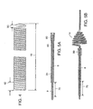
- Figure 4 illustrates a stretched turn having gaps 50 between adjacent turns of spring 18.
- inter-connected turns are further attached to each other and to the wire core 10, typically with an adhesive that can form a high-strength bond with a wide variety of substrates, particularly metal and polymeric materials.
- an adhesive that can form a high-strength bond with a wide variety of substrates, particularly metal and polymeric materials.
- the adhesive typically is cured by a conventional curing method, such as heat setting and air-drying.
- the adhesive comprise epoxy, preferably a UV curing adhesive that offers a secondary heat cure capability to allow areas shadowed from ultraviolet light to be cured with heat, such as that identified by the trade name Dynam 128-M-VT.
- other means of attachment may be employed, preferably welding or brazing.
- providing a colored portion 70 that possesses a color different from that of the rest of the device assists a user in determining whether the tapered helical coil is within or without sheath 24.
- the colored portion 70 will be visible to the user.
- the colored band 70 will no longer be visible to the user.
- Sheath 24 has a length that is less than the overall length of guidewire 9, but is considerably more than the length of wire core 10 forming the helical spring portion 14 so that a physician using device 8 can grasp the proximal end of the sheath when the device has been properly positioned within a patient.
- the inner diameter of sheath 24 is slightly greater than that of the diameter of the wrapped spring that surrounds helical spring portion. Its outer diameter depends, principally, on the wall thickness and strength required to retain the portion of wire core 10 forming spring 14 in a relatively straight configuration when the helical coil spring is drawn into the sleeve, i.e. sheath 24.
- sheath 24 is 75 cm long, has an inner diameter of 0.11 cm (0.043 inches) and an outer diameter of 0.17 cm (0.066 inches).
- the material of which the sheath is made also must be somewhat flexible, so that the sheath can be introduced into the body along with the rest of the device.
- the sheath is made of a flexible polymeric material such as that sold under the trade name PEBAX, and its distal portion is covered with a radiopaque material 80 to assist a user in locating the distal end of the sheath during a medical procedure.
- Figures 1 and 5B illustrate device 8 with sheath 24 positioned proximally of helical coil portion 14.
- the helical coil portion 14 is unconstrained and conforms to the tapered, helical configuration in which the nitinol (or other superelastic material) forming the coil portion was heat set.
- Figure 5A illustrates device 8 with the sheath 24 and helical coil portion 14 moved axially relative to each other so that the helical coil portion has been retracted into the sheath.
- the super-elastic qualities of the material forming the coil portion permit it to be deformed into an essentially straight configuration 60, in which the coil portion of guidewire 9 fits into the sheath whose inner diameter is only slightly (e.g., in the preferred embodiment about 0.013 cm (0.005 inches) greater than the outer diameter of the wrapped wire core. If the super-elastic portion of the coil wire that has been set in the helical coil configuration is then withdrawn from sheath 24, e.g., by moving the sheath proximally relative to the core wire (or the core wire distally relative to the sheath), it will reform the tapered helical spring configuration shown in Figure 5B.
- the deployed coil With the coil thus deployed, energy is applied to the stone or other calculus, in the same manner as in conventional lithotripsy, to break the stone into smaller fragments that may either be extracted or allowed normally to pass from the body.
- the deployed coil functions as a physical barrier, trapping the larger stone or calculus fragments either within the coiled structure or proximal to the coil.
- the smaller fragments e.g., those that are able to pass between the turns of the helical coil 14, are typically of such size that they can pass normally from the body.
- the super-elasticity of the material forming the coil particularly when combined with the tapered configuration, provides a flexible barrier that is able to absorb the kinetic energy of the fragments produced when a laser or other energy is used to comminute or ablate the calculus.
Landscapes
- Health & Medical Sciences (AREA)
- Surgery (AREA)
- Life Sciences & Earth Sciences (AREA)
- Heart & Thoracic Surgery (AREA)
- Molecular Biology (AREA)
- Vascular Medicine (AREA)
- Engineering & Computer Science (AREA)
- Biomedical Technology (AREA)
- Orthopedic Medicine & Surgery (AREA)
- Medical Informatics (AREA)
- Nuclear Medicine, Radiotherapy & Molecular Imaging (AREA)
- Animal Behavior & Ethology (AREA)
- General Health & Medical Sciences (AREA)
- Public Health (AREA)
- Veterinary Medicine (AREA)
- Media Introduction/Drainage Providing Device (AREA)
- Surgical Instruments (AREA)
- External Artificial Organs (AREA)
Abstract
Description
| With Stone Stopper | ||||
| Sample | Stone Type | Stone Size & Weight Before Breaking | Size & Weight of Debris Passed | Size & Weight of Debris Captured |
| 1A | Uric Acid | 6.34mm/ 1.42gm | 4mm/>.01gm | 4mm/.03gm |
| 1B | Uric Acid | 6.31mm/ 1.34gm | 3.5mm/.01gm | 5.5mm/.07gm |
| 2A | Uric Acid | 6.26mm/ 1.43gm | 3mm/>.01gm | 3mm/.07gm |
| 3A | Struvite/ Apatite | 6.71mm/ 1.31gm | 1mm/.01gm | 2mm/>.01gm |
| 4A | Cystic (hard) | 6.64mm/ 1.42gm | 4mm/>.01gm | 3.5mm/.02gm |
| 5A | Black | 6.55mm/ 1.29gm | 1mm/>.01gm | 2.5mm/>.01gm |
| Debris Type | Size of Debris & No. of Pieces | Size of Debris & No. of Pieces Not Entrained | Weight of Debris Not Entrained |
| Kidney Stone (Struvite, soft) | ∼8mm dia./1 pc. | <.5 to 3mm/20 to 25 | pcs..05 grams |
| Kidney Stone (hard) | ∼8mm dia./1 pc. | ∼6mm/1 | pc..10 grams |
| Walnut Shell | 2.8-3.9cm/16 pcs. | None passed | None passed |
| Walnut Shell | 2.8-3.9cm/4 pcs. | None passed' | None passed |
| Debris Type | Size of Debris & No. of Pieces | Weight of Debris | Distance Pulled |
| Kidney Stone (Struvite, soft) | 6 mm/2 pieces | .10 grams | 15cm |
| Walnut Shell | 2.8-3.9 cm/4 pieces. | .08 grams | 15cm |
| Walnut Shell | 2.8-3.9 cm/16 pieces | .30 grams | 15cm |
Claims (23)
- A medical device (8) comprising a generally longitudinally-extending wire core (10) containing at least one tapered portion (30, 32) and portions of differing cross-sectional diameters (31, 33, 34), wherein a portion of said core (10) more adjacent the distal end (11) thereof than the proximal end (13) thereof is wound to form a helical coil (14) which tapers in diameter from a larger diameter end at the proximal end (13) thereof to a smaller diameter end at the distal end (11) thereof, at least the portion of said core (10) forming said helical coil (14) being made of super-elastic deformable material, and including a wrapped helical spring (18,20) surrounding a longitudinally-extending portion of said core (10).
- The medical device (8) of claim 1, wherein said spring (18, 20) surrounds a major fraction of the overall length of said core (10).
- The medical device (8) of claim 1, wherein the distal and proximal ends of said spring (18, 20) are attached to said core (10).
- The medical device (8) of claim 1, wherein said spring (18, 20) includes a first spring portion (18) surrounding a first longitudinally-extending portion of said core (10) and a second spring (20) surrounding a second longitudinally-extending portion of said core (10), said second longitudinally-extending portion including said helical coil (14), said portions being adjacent to one another, and adjacent ends of said spring portions (18, 20) being attached to each other and to said core (10) in a region (22) proximal of said helical coil (14).
- The medical device (8) of claim 4, wherein the first spring portion (18) and said second spring portion (20) comprise wires of different diameters.
- The medical device (8) of claim 1, wherein the spring (18, 20) comprises stainless steel.
- The medical device (8) of claim 1, wherein a layer of a polymeric material (40) substantially covers the outer surface of said spring (18,20).
- The medical device (8) of claim 7, wherein the polymeric material (40) comprises a fluorinated polymer.
- The medical device (8) of claim 8, wherein the fluorinated polymer is polytetrafluoroethylene.
- The medical device (8) of claim 3, wherein the distal (11) and proximal (13) ends of said spring (18, 20) are attached to said core (10) by a weld or braze.
- The medical device (8) of claim 4, wherein the adjacent ends of said first (18) and second (20) spring sections are attached to each other and to said core (10) by an epoxy.
- The medical device (8) of claim 11, wherein the epoxy comprises epoxy which cures upon exposure to ultraviolet radiation.
- The medical device (8) of claim 1, wherein said core (10) comprises a super-elastic deformable material.
- The medical device (8) of claim 1, wherein said super-elastic deformable material is an alloy comprising nickel and titanium.
- The medical device of claim 14, wherein the alloy consists of nickel, titanium, and chromium.
- The medical device (8) of claim 1, wherein the wrapped helical spring (18, 20) surrounding a longitudinally-extending portion of said core (10) comprises a pair of wrapped helical springs (18, 20) surrounding the wire core (10), one of said springs (18, 20) extending distally from a point adjacent to the proximal end (13) of said core (10), the other of said springs (18, 20) extending proximally from a point adjacent the distal end (11) of said core (10) to a point proximal to said helical coil (14), one end of one of said springs (18, 20) being connected to one end of the other of said springs (18, 20) and to said core (10), and the other end of each of said springs (18, 20) being connected to the core (10).
- The medical device (8) of claim 1, wherein the longitudinally-extended wire core (10) is included in a guidewire (9), and further comprising a flexible tubular sheath (24) surrounding a portion of and being movable axially relative to said guidewire(9), the sheath (24) having an inner diameter that is greater than the diameter of the guidewire (9) other than a portion of said guidewire (9) forming said helical coil (14), such that said coil (14) deforms into a configuration having a maximum diameter not more than the inner diameter of said sheath (24) upon retraction into the sheath (24) and returns to a coil configuration having a maximum diameter greater than the outer diameter of said sheath (24) upon withdrawal from the sheath (24).
- The device (8) of claim 17, wherein said guidewire (9) includes one or more wrapped helical springs (18, 20) surrounding a longitudinally-extending portion of said core (10), and a polymeric material (40) covering a major fraction of the outer surface of said springs (18, 20).
- The medical device (8) of claim 1, wherein at least a portion of the device (8) includes a layer of radiopaque material.
- The medical device (8) of claim 19, wherein the radiopaque material comprises gold, platinum, tantalum, tungsten, iridium, rhodium, rhenium, or an alloy of two or more radiopaque materials.
- The medical device (8) of claim 17, wherein at least a portion of the flexible tubular sheath (24) comprises a layer of a radiopaque material.
- The medical device (8) of claim 21, wherein the radiopaque material comprises gold, platinum, tantalum, tungsten, iridium, rhodium, rhenium, or an alloy of two or more radiopaque materials.
- The medical device (8) of claim 16, wherein a portion of the coil (14) is covered with a radiopaque material.
Priority Applications (1)
| Application Number | Priority Date | Filing Date | Title |
|---|---|---|---|
| EP04022392A EP1493393A1 (en) | 1999-07-01 | 2000-06-30 | Medical retriever device |
Applications Claiming Priority (3)
| Application Number | Priority Date | Filing Date | Title |
|---|---|---|---|
| US09/347,591 US6620172B1 (en) | 1999-07-01 | 1999-07-01 | Entraining biological calculi |
| US347591 | 1999-07-01 | ||
| PCT/US2000/018377 WO2001001869A1 (en) | 1999-07-01 | 2000-06-30 | Medical retriever device |
Related Child Applications (1)
| Application Number | Title | Priority Date | Filing Date |
|---|---|---|---|
| EP04022392A Division EP1493393A1 (en) | 1999-07-01 | 2000-06-30 | Medical retriever device |
Publications (2)
| Publication Number | Publication Date |
|---|---|
| EP1191887A1 EP1191887A1 (en) | 2002-04-03 |
| EP1191887B1 true EP1191887B1 (en) | 2004-09-22 |
Family
ID=23364376
Family Applications (2)
| Application Number | Title | Priority Date | Filing Date |
|---|---|---|---|
| EP00947024A Expired - Lifetime EP1191887B1 (en) | 1999-07-01 | 2000-06-30 | Medical retriever device |
| EP04022392A Withdrawn EP1493393A1 (en) | 1999-07-01 | 2000-06-30 | Medical retriever device |
Family Applications After (1)
| Application Number | Title | Priority Date | Filing Date |
|---|---|---|---|
| EP04022392A Withdrawn EP1493393A1 (en) | 1999-07-01 | 2000-06-30 | Medical retriever device |
Country Status (7)
| Country | Link |
|---|---|
| US (3) | US6620172B1 (en) |
| EP (2) | EP1191887B1 (en) |
| JP (1) | JP2003503142A (en) |
| AT (1) | ATE276702T1 (en) |
| DE (1) | DE60014082T2 (en) |
| ES (1) | ES2228574T3 (en) |
| WO (1) | WO2001001869A1 (en) |
Families Citing this family (44)
| Publication number | Priority date | Publication date | Assignee | Title |
|---|---|---|---|---|
| US6758851B2 (en) * | 1999-02-02 | 2004-07-06 | Samuel Shiber | Vessel cleaner |
| US6702811B2 (en) | 1999-04-05 | 2004-03-09 | Medtronic, Inc. | Ablation catheter assembly with radially decreasing helix and method of use |
| US6620172B1 (en) * | 1999-07-01 | 2003-09-16 | Medsource Technologies, Inc. | Entraining biological calculi |
| US6951570B2 (en) | 2001-07-02 | 2005-10-04 | Rubicon Medical, Inc. | Methods, systems, and devices for deploying a filter from a filter device |
| US20030060842A1 (en) * | 2001-09-27 | 2003-03-27 | Yem Chin | Method and apparatus for measuring and controlling blade depth of a tissue cutting apparatus in an endoscopic catheter |
| US6740096B2 (en) | 2002-01-16 | 2004-05-25 | Scimed Life Systems, Inc. | Treatment and removal of objects in anatomical lumens |
| US20030191492A1 (en) * | 2002-04-05 | 2003-10-09 | Scimed Life Systems, Inc. | Radial coil expandable medical wire |
| US8774913B2 (en) | 2002-04-08 | 2014-07-08 | Medtronic Ardian Luxembourg S.A.R.L. | Methods and apparatus for intravasculary-induced neuromodulation |
| US7653438B2 (en) | 2002-04-08 | 2010-01-26 | Ardian, Inc. | Methods and apparatus for renal neuromodulation |
| US7682366B2 (en) | 2002-10-16 | 2010-03-23 | Olympus Corporation | Calculus manipulation apparatus |
| GB0309616D0 (en) | 2003-04-28 | 2003-06-04 | Angiomed Gmbh & Co | Loading and delivery of self-expanding stents |
| WO2005037062A2 (en) | 2003-10-14 | 2005-04-28 | Pluromed, Inc. | Confinement of kidney-stone fragments during lithotripsy |
| US20060074409A1 (en) * | 2004-10-05 | 2006-04-06 | Scimed Life Systems, Inc. | Detachable shaft medical retrieval device and related methods of use |
| US7955344B2 (en) * | 2005-04-01 | 2011-06-07 | Nexgen Medical Systems, Inc. | Thrombus removal system and process |
| US7955345B2 (en) * | 2005-04-01 | 2011-06-07 | Nexgen Medical Systems, Inc. | Thrombus removal system and process |
| US20060224178A1 (en) * | 2005-04-05 | 2006-10-05 | Boston Scientific Scimed, Inc. | Expandable medical retrieval device and related methods of use |
| PT2601972E (en) | 2005-05-02 | 2015-02-09 | Gen Hospital Corp | Non-lithotripsic kidney-stone therapy |
| US20070185520A1 (en) * | 2006-02-07 | 2007-08-09 | Boston Scientific Scimed, Inc. | Detachable medical immobilization device and related methods of use |
| WO2007092506A2 (en) * | 2006-02-08 | 2007-08-16 | Vance Products Incorporated D/B/A Cook Urological Incorporated | Irrigating catch and removal device |
| US7785317B2 (en) * | 2006-03-29 | 2010-08-31 | Codman & Shurtleff, Inc. | Joined metal tubing and method of manufacture |
| KR20160003890A (en) * | 2006-09-29 | 2016-01-11 | 플루로메드, 인코포레이티드 | Methods for preventing retropulsion of concretions and fragments during lithotripsy |
| US10076346B2 (en) | 2007-04-17 | 2018-09-18 | Covidien Lp | Complex wire formed devices |
| GB0816965D0 (en) * | 2008-09-16 | 2008-10-22 | Angiomed Ag | Stent device adhesively bonded to a stent device pusher |
| GB0901496D0 (en) | 2009-01-29 | 2009-03-11 | Angiomed Ag | Delivery device for delivering a stent device |
| GB0909319D0 (en) | 2009-05-29 | 2009-07-15 | Angiomed Ag | Transluminal delivery system |
| EP2485679A1 (en) * | 2009-10-08 | 2012-08-15 | Cook Incorporated | Vascular implant retrieval assembly and tool for the same |
| US8152941B2 (en) | 2009-11-02 | 2012-04-10 | Saes Smart Materials | Ni-Ti semi-finished products and related methods |
| US8764779B2 (en) * | 2010-05-13 | 2014-07-01 | Rex Medical, L.P. | Rotational thrombectomy wire |
| CN202654229U (en) | 2010-10-25 | 2013-01-09 | 美敦力Af卢森堡有限责任公司 | Catheter device for curing human patients by renal denervation |
| EP2691141A4 (en) * | 2011-03-30 | 2014-08-27 | Univ Cornell | INTRALUMINAL ACCESS APPARATUS AND METHODS OF USING THE SAME |
| EP2846724B1 (en) | 2012-05-11 | 2016-11-09 | Medtronic Ardian Luxembourg S.à.r.l. | Multi-electrode catheter assemblies for renal neuromodulation and associated systems |
| US9095321B2 (en) | 2012-11-21 | 2015-08-04 | Medtronic Ardian Luxembourg S.A.R.L. | Cryotherapeutic devices having integral multi-helical balloons and methods of making the same |
| WO2014081942A1 (en) | 2012-11-21 | 2014-05-30 | Concert Medical, Llc | Preformed guidewire |
| US9179974B2 (en) | 2013-03-15 | 2015-11-10 | Medtronic Ardian Luxembourg S.A.R.L. | Helical push wire electrode |
| US9360124B2 (en) | 2013-03-15 | 2016-06-07 | Cook Medical Technologies Llc | Bi-directional valve device for selective control of fluid flow through multiple converging paths |
| US20150073515A1 (en) | 2013-09-09 | 2015-03-12 | Medtronic Ardian Luxembourg S.a.r.I. | Neuromodulation Catheter Devices and Systems Having Energy Delivering Thermocouple Assemblies and Associated Methods |
| US10736690B2 (en) | 2014-04-24 | 2020-08-11 | Medtronic Ardian Luxembourg S.A.R.L. | Neuromodulation catheters and associated systems and methods |
| WO2017127595A1 (en) | 2016-01-22 | 2017-07-27 | Boston Scientific Scimed, Inc. | Retrieval system |
| CN112118794B (en) | 2018-04-30 | 2024-12-06 | 波士顿科学有限公司 | System and method for object size estimation |
| US10667833B2 (en) * | 2018-06-08 | 2020-06-02 | Neuravi Limited | Guidewire with an atraumatic clot-circumventing configured distal end for use in an endovascular medical system |
| US11350956B2 (en) | 2019-08-01 | 2022-06-07 | Carnelian Medical LLC | Snare device with anti-skewing |
| US12274462B2 (en) | 2019-08-01 | 2025-04-15 | Carnelian Medical LLC | Snare device with anti-skewing |
| EP4301251B1 (en) | 2021-03-04 | 2025-12-03 | Carnelian Medical LLC | Snare device |
| CN117122377B (en) * | 2023-04-04 | 2024-04-23 | 上海中医药大学附属曙光医院 | Stone removal guide wire and ureteroscope |
Family Cites Families (34)
| Publication number | Priority date | Publication date | Assignee | Title |
|---|---|---|---|---|
| US843951A (en) | 1906-04-24 | 1907-02-12 | Joseph S Klock | Gape-worm extractor. |
| US2756752A (en) | 1953-12-23 | 1956-07-31 | Scherlis Irving | Surgical instrument |
| US2943626A (en) | 1957-01-31 | 1960-07-05 | Dormia Enrico | Instruments for the extraction of foreign bodies |
| US3472230A (en) | 1966-12-19 | 1969-10-14 | Fogarty T J | Umbrella catheter |
| JPS558709A (en) * | 1978-07-01 | 1980-01-22 | Chiyouei Takahashi | Curve operating device of medical coelom inside inserting tool |
| US4299225A (en) | 1979-04-26 | 1981-11-10 | The Southeastern Research Foundation | Surgical extracter |
| IT1126526B (en) | 1979-12-07 | 1986-05-21 | Enrico Dormia | SURGICAL EXTRACTOR TO REMOVE FOREIGN BODIES THAT ARE FOUND IN THE NATURAL ROUTES OF THE HUMAN BODY, AS CALCULATIONS AND SIMILAR |
| US4295464A (en) | 1980-03-21 | 1981-10-20 | Shihata Alfred A | Ureteric stone extractor with two ballooned catheters |
| US4425908A (en) | 1981-10-22 | 1984-01-17 | Beth Israel Hospital | Blood clot filter |
| US4807626A (en) | 1985-02-14 | 1989-02-28 | Mcgirr Douglas B | Stone extractor and method |
| US4706671A (en) * | 1985-05-02 | 1987-11-17 | Weinrib Harry P | Catheter with coiled tip |
| US4793348A (en) | 1986-11-15 | 1988-12-27 | Palmaz Julio C | Balloon expandable vena cava filter to prevent migration of lower extremity venous clots into the pulmonary circulation |
| JPS63238872A (en) | 1987-03-25 | 1988-10-04 | テルモ株式会社 | Instrument for securing inner diameter of cavity of tubular organ and catheter equipped therewith |
| US4817600A (en) | 1987-05-22 | 1989-04-04 | Medi-Tech, Inc. | Implantable filter |
| US5054501A (en) * | 1990-05-16 | 1991-10-08 | Brigham & Women's Hospital | Steerable guide wire for cannulation of tubular or vascular organs |
| US5195954A (en) | 1990-06-26 | 1993-03-23 | Schnepp Pesch Wolfram | Apparatus for the removal of deposits in vessels and organs of animals |
| US5626605A (en) | 1991-12-30 | 1997-05-06 | Scimed Life Systems, Inc. | Thrombosis filter |
| JP2552820B2 (en) | 1992-09-23 | 1996-11-13 | ターゲット セラピューティクス,インコーポレイテッド | Medical recovery equipment |
| US5490859A (en) | 1992-11-13 | 1996-02-13 | Scimed Life Systems, Inc. | Expandable intravascular occlusion material removal devices and methods of use |
| US5330483A (en) | 1992-12-18 | 1994-07-19 | Advanced Surgical Inc. | Specimen reduction device |
| JPH09510637A (en) * | 1994-03-18 | 1997-10-28 | クック インコーポレイティッド | Spiral embolization coil |
| US6117157A (en) * | 1994-03-18 | 2000-09-12 | Cook Incorporated | Helical embolization coil |
| US5601595A (en) | 1994-10-25 | 1997-02-11 | Scimed Life Systems, Inc. | Remobable thrombus filter |
| US5895398A (en) * | 1996-02-02 | 1999-04-20 | The Regents Of The University Of California | Method of using a clot capture coil |
| IT241710Y1 (en) * | 1996-06-20 | 2001-05-17 | Fina Ernesto | DEVICE FOR ENDOCAVITARY ELECTROLYSIS OF URINE CALCULATIONS OELECTROLITOLYSIS |
| US5669933A (en) | 1996-07-17 | 1997-09-23 | Nitinol Medical Technologies, Inc. | Removable embolus blood clot filter |
| EP0968015A4 (en) | 1996-11-26 | 2004-12-29 | Medtronic Inc | SYSTEM AND METHODS FOR REMOVING CLOCKS FROM BLOOD VESSELS |
| ES2214698T3 (en) * | 1997-02-24 | 2004-09-16 | Cook Urological Inc. | FOLDING FILTER BASKET FOR MEDICAL USE. |
| US6066149A (en) * | 1997-09-30 | 2000-05-23 | Target Therapeutics, Inc. | Mechanical clot treatment device with distal filter |
| CA2309428A1 (en) | 1997-11-07 | 1999-05-20 | Prolifix Medical, Inc. | Methods and systems for treating obstructions in a body lumen |
| US6156046A (en) * | 1997-11-07 | 2000-12-05 | Prolifix Medical, Inc. | Methods and systems for treating obstructions in a body lumen |
| US5895308A (en) * | 1998-03-24 | 1999-04-20 | Spector; Donald | Sound-producing soft toy missile |
| US6500182B2 (en) * | 1998-03-27 | 2002-12-31 | Cook Urological, Incorporated | Minimally-invasive medical retrieval device |
| US6620172B1 (en) * | 1999-07-01 | 2003-09-16 | Medsource Technologies, Inc. | Entraining biological calculi |
-
1999
- 1999-07-01 US US09/347,591 patent/US6620172B1/en not_active Expired - Lifetime
-
2000
- 2000-06-30 EP EP00947024A patent/EP1191887B1/en not_active Expired - Lifetime
- 2000-06-30 EP EP04022392A patent/EP1493393A1/en not_active Withdrawn
- 2000-06-30 JP JP2001507375A patent/JP2003503142A/en active Pending
- 2000-06-30 AT AT00947024T patent/ATE276702T1/en active
- 2000-06-30 ES ES00947024T patent/ES2228574T3/en not_active Expired - Lifetime
- 2000-06-30 WO PCT/US2000/018377 patent/WO2001001869A1/en not_active Ceased
- 2000-06-30 DE DE60014082T patent/DE60014082T2/en not_active Expired - Lifetime
-
2001
- 2001-05-21 US US09/862,068 patent/US20010031971A1/en not_active Abandoned
-
2003
- 2003-09-16 US US10/663,361 patent/US20050192593A1/en not_active Abandoned
Also Published As
| Publication number | Publication date |
|---|---|
| WO2001001869A1 (en) | 2001-01-11 |
| US20050192593A1 (en) | 2005-09-01 |
| US6620172B1 (en) | 2003-09-16 |
| DE60014082T2 (en) | 2005-11-17 |
| ATE276702T1 (en) | 2004-10-15 |
| EP1493393A1 (en) | 2005-01-05 |
| JP2003503142A (en) | 2003-01-28 |
| ES2228574T3 (en) | 2005-04-16 |
| EP1191887A1 (en) | 2002-04-03 |
| DE60014082D1 (en) | 2004-10-28 |
| US20010031971A1 (en) | 2001-10-18 |
Similar Documents
| Publication | Publication Date | Title |
|---|---|---|
| US6620172B1 (en) | Entraining biological calculi | |
| US8540729B2 (en) | Treatment and removal of objects in anatomical lumens | |
| US8382771B2 (en) | Radial coil expandable medical wire | |
| US8979870B2 (en) | Distal release retrieval assembly and related methods of use | |
| EP1408854B1 (en) | Surgical grasping device | |
| JP4152071B2 (en) | Mechanical clot treatment device using distal filter | |
| US8608761B2 (en) | Thrombus removal device | |
| CA2304562C (en) | Releasable basket | |
| JP3366835B2 (en) | Mechanical clot treatment device | |
| US7879066B2 (en) | Apparatus for occluding body lumens | |
| EP1838227A1 (en) | Releasable medical basket and related methods of use | |
| US20060200171A1 (en) | Medical retrieval device and related methods of use |
Legal Events
| Date | Code | Title | Description |
|---|---|---|---|
| PUAI | Public reference made under article 153(3) epc to a published international application that has entered the european phase |
Free format text: ORIGINAL CODE: 0009012 |
|
| 17P | Request for examination filed |
Effective date: 20020104 |
|
| AK | Designated contracting states |
Kind code of ref document: A1 Designated state(s): AT BE CH CY DE DK ES FI FR GB GR IE IT LI LU MC NL PT SE |
|
| 17Q | First examination report despatched |
Effective date: 20030319 |
|
| GRAP | Despatch of communication of intention to grant a patent |
Free format text: ORIGINAL CODE: EPIDOSNIGR1 |
|
| GRAS | Grant fee paid |
Free format text: ORIGINAL CODE: EPIDOSNIGR3 |
|
| GRAA | (expected) grant |
Free format text: ORIGINAL CODE: 0009210 |
|
| AK | Designated contracting states |
Kind code of ref document: B1 Designated state(s): AT BE CH CY DE DK ES FI FR GB GR IE IT LI LU MC NL PT SE |
|
| PG25 | Lapsed in a contracting state [announced via postgrant information from national office to epo] |
Ref country code: FI Free format text: LAPSE BECAUSE OF FAILURE TO SUBMIT A TRANSLATION OF THE DESCRIPTION OR TO PAY THE FEE WITHIN THE PRESCRIBED TIME-LIMIT Effective date: 20040922 |
|
| REG | Reference to a national code |
Ref country code: GB Ref legal event code: FG4D |
|
| REG | Reference to a national code |
Ref country code: CH Ref legal event code: EP |
|
| REG | Reference to a national code |
Ref country code: IE Ref legal event code: FG4D |
|
| REF | Corresponds to: |
Ref document number: 60014082 Country of ref document: DE Date of ref document: 20041028 Kind code of ref document: P |
|
| PG25 | Lapsed in a contracting state [announced via postgrant information from national office to epo] |
Ref country code: GR Free format text: LAPSE BECAUSE OF FAILURE TO SUBMIT A TRANSLATION OF THE DESCRIPTION OR TO PAY THE FEE WITHIN THE PRESCRIBED TIME-LIMIT Effective date: 20041222 Ref country code: SE Free format text: LAPSE BECAUSE OF FAILURE TO SUBMIT A TRANSLATION OF THE DESCRIPTION OR TO PAY THE FEE WITHIN THE PRESCRIBED TIME-LIMIT Effective date: 20041222 Ref country code: DK Free format text: LAPSE BECAUSE OF FAILURE TO SUBMIT A TRANSLATION OF THE DESCRIPTION OR TO PAY THE FEE WITHIN THE PRESCRIBED TIME-LIMIT Effective date: 20041222 |
|
| REG | Reference to a national code |
Ref country code: CH Ref legal event code: NV Representative=s name: E. BLUM & CO. PATENTANWAELTE |
|
| REG | Reference to a national code |
Ref country code: ES Ref legal event code: FG2A Ref document number: 2228574 Country of ref document: ES Kind code of ref document: T3 |
|
| ET | Fr: translation filed | ||
| RAP2 | Party data changed (patent owner data changed or rights of a patent transferred) |
Owner name: MEDSOURCE TECHNOLOGIES, LLC |
|
| PG25 | Lapsed in a contracting state [announced via postgrant information from national office to epo] |
Ref country code: CY Free format text: LAPSE BECAUSE OF FAILURE TO SUBMIT A TRANSLATION OF THE DESCRIPTION OR TO PAY THE FEE WITHIN THE PRESCRIBED TIME-LIMIT Effective date: 20050630 |
|
| PLBE | No opposition filed within time limit |
Free format text: ORIGINAL CODE: 0009261 |
|
| STAA | Information on the status of an ep patent application or granted ep patent |
Free format text: STATUS: NO OPPOSITION FILED WITHIN TIME LIMIT |
|
| NLT2 | Nl: modifications (of names), taken from the european patent patent bulletin |
Owner name: MEDSOURCE TECHNOLOGIES, LLC Effective date: 20050629 |
|
| 26N | No opposition filed |
Effective date: 20050623 |
|
| REG | Reference to a national code |
Ref country code: GB Ref legal event code: 732E |
|
| REG | Reference to a national code |
Ref country code: FR Ref legal event code: TP |
|
| REG | Reference to a national code |
Ref country code: CH Ref legal event code: PUE Owner name: MEDSOURCE TECHNOLOGIES, LLC Free format text: THE MICROSPRING COMPANY, LLC#BUILDING A, 77 ACCORD PARK DRIVE#NORWELL, MA 02061 (US) -TRANSFER TO- MEDSOURCE TECHNOLOGIES, LLC#110 CHESHIRE LANE, SUITE 100#MINNEAPOLIS, MN 55305 (US) |
|
| NLS | Nl: assignments of ep-patents |
Owner name: MEDSOURCE TECHNOLOGIES, LLC Effective date: 20060308 |
|
| REG | Reference to a national code |
Ref country code: CH Ref legal event code: PFA Owner name: MEDSOURCE TECHNOLOGIES, LLC Free format text: MEDSOURCE TECHNOLOGIES, LLC#110 CHESHIRE LANE, SUITE 100#MINNEAPOLIS, MN 55305 (US) -TRANSFER TO- MEDSOURCE TECHNOLOGIES, LLC#110 CHESHIRE LANE, SUITE 100#MINNEAPOLIS, MN 55305 (US) |
|
| PG25 | Lapsed in a contracting state [announced via postgrant information from national office to epo] |
Ref country code: PT Free format text: LAPSE BECAUSE OF NON-PAYMENT OF DUE FEES Effective date: 20050222 |
|
| REG | Reference to a national code |
Ref country code: FR Ref legal event code: PLFP Year of fee payment: 17 |
|
| REG | Reference to a national code |
Ref country code: FR Ref legal event code: PLFP Year of fee payment: 18 |
|
| REG | Reference to a national code |
Ref country code: FR Ref legal event code: PLFP Year of fee payment: 19 |
|
| REG | Reference to a national code |
Ref country code: GB Ref legal event code: 732E Free format text: REGISTERED BETWEEN 20180517 AND 20180523 |
|
| PGFP | Annual fee paid to national office [announced via postgrant information from national office to epo] |
Ref country code: NL Payment date: 20190612 Year of fee payment: 20 Ref country code: IE Payment date: 20190610 Year of fee payment: 20 Ref country code: DE Payment date: 20190618 Year of fee payment: 20 Ref country code: IT Payment date: 20190620 Year of fee payment: 20 Ref country code: MC Payment date: 20190529 Year of fee payment: 20 Ref country code: LU Payment date: 20190610 Year of fee payment: 20 |
|
| PGFP | Annual fee paid to national office [announced via postgrant information from national office to epo] |
Ref country code: BE Payment date: 20190417 Year of fee payment: 20 Ref country code: FR Payment date: 20190510 Year of fee payment: 20 |
|
| PGFP | Annual fee paid to national office [announced via postgrant information from national office to epo] |
Ref country code: CH Payment date: 20190614 Year of fee payment: 20 |
|
| PGFP | Annual fee paid to national office [announced via postgrant information from national office to epo] |
Ref country code: AT Payment date: 20190528 Year of fee payment: 20 Ref country code: ES Payment date: 20190701 Year of fee payment: 20 Ref country code: GB Payment date: 20190626 Year of fee payment: 20 |
|
| REG | Reference to a national code |
Ref country code: DE Ref legal event code: R071 Ref document number: 60014082 Country of ref document: DE |
|
| REG | Reference to a national code |
Ref country code: NL Ref legal event code: MK Effective date: 20200629 |
|
| REG | Reference to a national code |
Ref country code: CH Ref legal event code: PL |
|
| REG | Reference to a national code |
Ref country code: GB Ref legal event code: PE20 Expiry date: 20200629 Ref country code: IE Ref legal event code: MK9A |
|
| REG | Reference to a national code |
Ref country code: AT Ref legal event code: MK07 Ref document number: 276702 Country of ref document: AT Kind code of ref document: T Effective date: 20200630 |
|
| REG | Reference to a national code |
Ref country code: BE Ref legal event code: MK Effective date: 20200630 |
|
| PG25 | Lapsed in a contracting state [announced via postgrant information from national office to epo] |
Ref country code: GB Free format text: LAPSE BECAUSE OF EXPIRATION OF PROTECTION Effective date: 20200629 |
|
| PG25 | Lapsed in a contracting state [announced via postgrant information from national office to epo] |
Ref country code: IE Free format text: LAPSE BECAUSE OF EXPIRATION OF PROTECTION Effective date: 20200630 |
|
| REG | Reference to a national code |
Ref country code: ES Ref legal event code: FD2A Effective date: 20220128 |
|
| PG25 | Lapsed in a contracting state [announced via postgrant information from national office to epo] |
Ref country code: ES Free format text: LAPSE BECAUSE OF EXPIRATION OF PROTECTION Effective date: 20200701 |