EP1191842B1 - Insecticidal liquid bait station - Google Patents
Insecticidal liquid bait station Download PDFInfo
- Publication number
- EP1191842B1 EP1191842B1 EP00945046A EP00945046A EP1191842B1 EP 1191842 B1 EP1191842 B1 EP 1191842B1 EP 00945046 A EP00945046 A EP 00945046A EP 00945046 A EP00945046 A EP 00945046A EP 1191842 B1 EP1191842 B1 EP 1191842B1
- Authority
- EP
- European Patent Office
- Prior art keywords
- bait
- liquid
- reservoir
- insect
- wall
- Prior art date
- Legal status (The legal status is an assumption and is not a legal conclusion. Google has not performed a legal analysis and makes no representation as to the accuracy of the status listed.)
- Expired - Lifetime
Links
- 239000007788 liquid Substances 0.000 title claims abstract description 267
- 230000000749 insecticidal effect Effects 0.000 title description 5
- 241000238631 Hexapoda Species 0.000 claims abstract description 149
- 230000004913 activation Effects 0.000 claims abstract description 75
- 239000002917 insecticide Substances 0.000 claims abstract description 7
- 238000007789 sealing Methods 0.000 claims abstract description 6
- 239000007787 solid Substances 0.000 claims description 53
- 230000009193 crawling Effects 0.000 claims description 21
- 239000011148 porous material Substances 0.000 claims description 20
- 238000000034 method Methods 0.000 claims description 3
- 230000032258 transport Effects 0.000 description 76
- 239000000463 material Substances 0.000 description 20
- 230000009471 action Effects 0.000 description 12
- 239000003440 toxic substance Substances 0.000 description 9
- 241001674044 Blattodea Species 0.000 description 8
- 239000011888 foil Substances 0.000 description 7
- XLYOFNOQVPJJNP-UHFFFAOYSA-N water Substances O XLYOFNOQVPJJNP-UHFFFAOYSA-N 0.000 description 6
- 239000012530 fluid Substances 0.000 description 5
- 238000004891 communication Methods 0.000 description 4
- 239000000203 mixture Substances 0.000 description 4
- 231100000614 poison Toxicity 0.000 description 4
- 230000007096 poisonous effect Effects 0.000 description 4
- -1 polyethylene Polymers 0.000 description 4
- 230000003111 delayed effect Effects 0.000 description 3
- 238000009472 formulation Methods 0.000 description 3
- 239000000243 solution Substances 0.000 description 3
- 231100000167 toxic agent Toxicity 0.000 description 3
- QYYMDNHUJFIDDQ-UHFFFAOYSA-N 5-chloro-2-methyl-1,2-thiazol-3-one;2-methyl-1,2-thiazol-3-one Chemical compound CN1SC=CC1=O.CN1SC(Cl)=CC1=O QYYMDNHUJFIDDQ-UHFFFAOYSA-N 0.000 description 2
- 239000004698 Polyethylene Substances 0.000 description 2
- 239000004743 Polypropylene Substances 0.000 description 2
- 241000209149 Zea Species 0.000 description 2
- 235000005824 Zea mays ssp. parviglumis Nutrition 0.000 description 2
- 235000002017 Zea mays subsp mays Nutrition 0.000 description 2
- KGBXLFKZBHKPEV-UHFFFAOYSA-N boric acid Chemical compound OB(O)O KGBXLFKZBHKPEV-UHFFFAOYSA-N 0.000 description 2
- 239000004327 boric acid Substances 0.000 description 2
- 235000005822 corn Nutrition 0.000 description 2
- 235000003599 food sweetener Nutrition 0.000 description 2
- 229920000573 polyethylene Polymers 0.000 description 2
- 229920001155 polypropylene Polymers 0.000 description 2
- 239000003755 preservative agent Substances 0.000 description 2
- 230000002335 preservative effect Effects 0.000 description 2
- 239000003765 sweetening agent Substances 0.000 description 2
- 239000004215 Carbon black (E152) Substances 0.000 description 1
- 239000005944 Chlorpyrifos Substances 0.000 description 1
- CZMRCDWAGMRECN-UGDNZRGBSA-N Sucrose Chemical compound O[C@H]1[C@H](O)[C@@H](CO)O[C@@]1(CO)O[C@@H]1[C@H](O)[C@@H](O)[C@H](O)[C@@H](CO)O1 CZMRCDWAGMRECN-UGDNZRGBSA-N 0.000 description 1
- 229930006000 Sucrose Natural products 0.000 description 1
- 230000003213 activating effect Effects 0.000 description 1
- 239000013011 aqueous formulation Substances 0.000 description 1
- 239000005667 attractant Substances 0.000 description 1
- 229920001525 carrageenan Polymers 0.000 description 1
- 229910010293 ceramic material Inorganic materials 0.000 description 1
- 230000031902 chemoattractant activity Effects 0.000 description 1
- SBPBAQFWLVIOKP-UHFFFAOYSA-N chlorpyrifos Chemical compound CCOP(=S)(OCC)OC1=NC(Cl)=C(Cl)C=C1Cl SBPBAQFWLVIOKP-UHFFFAOYSA-N 0.000 description 1
- 230000001877 deodorizing effect Effects 0.000 description 1
- 239000003995 emulsifying agent Substances 0.000 description 1
- 239000000835 fiber Substances 0.000 description 1
- 239000000499 gel Substances 0.000 description 1
- 239000003292 glue Substances 0.000 description 1
- 229930195733 hydrocarbon Natural products 0.000 description 1
- 150000002430 hydrocarbons Chemical class 0.000 description 1
- 235000012054 meals Nutrition 0.000 description 1
- 238000012986 modification Methods 0.000 description 1
- 230000004048 modification Effects 0.000 description 1
- 230000002093 peripheral effect Effects 0.000 description 1
- 239000004033 plastic Substances 0.000 description 1
- 229920003023 plastic Polymers 0.000 description 1
- 229920000642 polymer Polymers 0.000 description 1
- 239000000843 powder Substances 0.000 description 1
- 238000003825 pressing Methods 0.000 description 1
- 239000005720 sucrose Substances 0.000 description 1
- 231100000331 toxic Toxicity 0.000 description 1
- 230000002588 toxic effect Effects 0.000 description 1
Images






Classifications
-
- A—HUMAN NECESSITIES
- A01—AGRICULTURE; FORESTRY; ANIMAL HUSBANDRY; HUNTING; TRAPPING; FISHING
- A01M—CATCHING, TRAPPING OR SCARING OF ANIMALS; APPARATUS FOR THE DESTRUCTION OF NOXIOUS ANIMALS OR NOXIOUS PLANTS
- A01M1/00—Stationary means for catching or killing insects
- A01M1/20—Poisoning, narcotising, or burning insects
-
- A—HUMAN NECESSITIES
- A01—AGRICULTURE; FORESTRY; ANIMAL HUSBANDRY; HUNTING; TRAPPING; FISHING
- A01M—CATCHING, TRAPPING OR SCARING OF ANIMALS; APPARATUS FOR THE DESTRUCTION OF NOXIOUS ANIMALS OR NOXIOUS PLANTS
- A01M1/00—Stationary means for catching or killing insects
- A01M1/20—Poisoning, narcotising, or burning insects
- A01M1/2005—Poisoning insects using bait stations
- A01M1/2011—Poisoning insects using bait stations for crawling insects
-
- A—HUMAN NECESSITIES
- A01—AGRICULTURE; FORESTRY; ANIMAL HUSBANDRY; HUNTING; TRAPPING; FISHING
- A01M—CATCHING, TRAPPING OR SCARING OF ANIMALS; APPARATUS FOR THE DESTRUCTION OF NOXIOUS ANIMALS OR NOXIOUS PLANTS
- A01M1/00—Stationary means for catching or killing insects
- A01M1/20—Poisoning, narcotising, or burning insects
- A01M1/2022—Poisoning or narcotising insects by vaporising an insecticide
- A01M1/2027—Poisoning or narcotising insects by vaporising an insecticide without heating
- A01M1/2044—Holders or dispensers for liquid insecticide, e.g. using wicks
-
- A—HUMAN NECESSITIES
- A01—AGRICULTURE; FORESTRY; ANIMAL HUSBANDRY; HUNTING; TRAPPING; FISHING
- A01M—CATCHING, TRAPPING OR SCARING OF ANIMALS; APPARATUS FOR THE DESTRUCTION OF NOXIOUS ANIMALS OR NOXIOUS PLANTS
- A01M2200/00—Kind of animal
- A01M2200/01—Insects
- A01M2200/011—Crawling insects
Definitions
- the present invention relates to insecticidal bait stations for the control of insects such as cockroaches.
- U.S. patent 5,033,229 discloses a bait station for passive control of insects, particularly roaches, that provides a source of a liquid bait-toxicant solution, which roaches seek
- U.S. patent 5,501,033 discloses techniques for the controlled delivery of a liquid insecticidal bait along a vertical axis.
- Insect control devices configured to hold both a liquid and a solid bait and/or toxicant preparation are also known.
- U.S. patent 2,167,978 discloses an insect control device having a paralyzing insect powder as well as a liquid attractant (water) wicked upwardly to a desired position from a reservoir;
- U.S. patent 5,339,563 discloses the use of a liquid positioned adjacent an insecticidal material; and
- U.S. patent 5,749,168 discloses an insect control device having liquid and solid bait.
- the liquid is a trapping solution, preferably comprising a mixture of water and household glue.
- Insect bait stations that offer a solid poisonous meal and a poisonous drink are quite advantageous, as crawling insects will be able to consume both solid and liquid poisonous materials when looking for water or similar liquids.
- currently available insect control devices that include solid and liquid bait do not provide for a convenient means for sealing the liquid bait during transport and storage and for releasing the liquid bait when the insect bait station is placed into service.
- Such a station has a reservoir for holding a liquid bait, the reservoir having a mouth and a closure for sealing the mouth such that the liquid bait is contained in the reservoir; a piercer for opening the closure of the reservoir such that a liquid wicking device positioned in the mouth of the reservoir may transport the liquid bait from the reservoir and through the mouth of the reservoir; and an activation member for moving the piercer into contact with the closure of the reservoir to open the closure, wherein the station also comprises an insecticide and a solid bait.
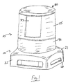
- the insect bait station 10 includes a base 20 having an outer wall 22, a slightly inclined portion 21 extending inwardly from the outer wall 22, and a cylindrical wall 36 extending upwardly from the inclined portion 21.
- the outer wall 22 of the base 20 has an opening 28 that provides access into the insect bait station 10.
- the insect bait station 10 also includes a cylindrical wall portion 35 affixed to the top of the cylindrical wall 36 of the base 20.
- the cylindrical wall portion 35 may include a transparent window 37 that enables a user to view inside the insect bait station 10.
- the insect bait station 10 also includes an activation member 80 that may be press fit into an upper portion of the cylindrical wall portion 35.
- the activation member 80 and the cylindrical wall portion 35 are dimensioned such that the activation member may be moved downward in relation to the cylindrical wall portion 35 by applying pressure to a top surface of the activation member 80.
- the components of the insect bait station are manufactured from a polymeric material such as polyethylene or polypropylene.
- the base 20 includes a cylindrical inner wall 24 that is inwardly spaced from the outer wall 22 so as to define a solid bait chamber 26 between the outer wall 22 and the inner wall 24.
- the solid bait chamber 26 contains a solid bait 34.
- the solid bait 34 may be any of a number of solid bait-toxicant formulations, preferably one having a delayed kill action.
- a suitable solid bait-toxicant comprises: boric acid (@ 2% by weight), sugar/corn Sweetener (@ 15% by weight), preservative such as that commonly sold under the trademark "Legend MK" (@ 0.2% by weight), carageenan (@ 1.2% by weight) and water (@ 81.6% by weight).
- the inner wall 24 of the base 20 also defines a liquid bait holding tank 30 in an inner region of the base 20.
- the liquid bait holding tank 30 has a floor 131 and a conical piercer 160 that extends upwardly from the floor 131.
- the insect bait station 10 shown in Figures 3A and 3B also includes a reservoir 40 for holding a liquid bait 42.
- the liquid bait 42 may be an aqueous bait-toxicant formulation, preferably one having a delayed kill action.
- An example of a suitable bait-toxicant formulation would comprise 9.5% chlorpyrifos insecticide, 5.0% isoparrafinic hydrocarbon (BP 208°-289° C), 1.0% HLB-12 emulsifier, 10.0% sucrose, and 83.5% water.
- boric acid (@ 2% by weight), sugar/corn Sweetener (@15% by weight), preservative such as that commonly sold under the trademark "Legend MK” by Rohm & Haas (@ 0.2% by weight) and water (@ 82.8% by weight).
- preservative such as that commonly sold under the trademark "Legend MK” by Rohm & Haas (@ 0.2% by weight) and water (@ 82.8% by weight).
- Other aqueous formulations containing insecticides and bait components may also be used.
- the reservoir 40 may be made from a plastic material, and has a body 43 that terminates in a mouth 44.
- the mouth 44 is sealed so as to contain the liquid bait 42 in the reservoir 40 by way of a closure 46.
- the closure 46 may be any material suitable for sealing the mouth 44 of the reservoir 40. However, the closure material must be capable of being punctured by the piercer 160 as will be described below.
- One suitable material for the closure 46 is a foil material commonly used as a safety seal on pharmaceutical containers.
- the reservoir 40 is arranged in the insect bait station 10 in an inverted position as shown in Figures 3A and 3B. One end of the reservoir 40 is arranged in abutting relationship with an underside 84 of the activation member 80 between spaced apart mounting tabs 81.
- the mouth 44 of the reservoir 40 fits snugly against an inner surface of the cylindrical inner wall 24.
- the mouth 44 of the reservoir 40 is positioned between inwardly directed protrusions 38a and 38b on the inner surface of the inner wall 24 in order to maintain the sealed reservoir 40 in a storage position as shown in Figure 3A.
- the reservoir 40 also includes a liquid transport device 148 positioned in the mouth 44 of the reservoir 40.
- the liquid transport device 148 may be a member having capillary channels for transferring liquid by capillary action or may be a body formed from a porous wicking material such as a fiber wick. Many materials are suitable for wicking liquid through a body of material. For example, fibrous or porous polymeric materials will wick liquid. Sponges with small pores, capillaries, and lattice matrices of cellulosic materials or polymers all can draw liquid to a surface. In the present invention, cellulosic, polyolefinic (e.g., polyethylene and polypropylene), and ceramic materials are preferred for the wicking material.
- Figure 3A shows the insect bait station 10 before any liquid bait 42 would be accessible to a crawling insect.
- the configuration of the insect bait station shown in Figure 3A prevents any liquid bait 42 from leaking or spilling when the insect bait station 20 is transported before activation by a user.
- a user applies a downward force to the activation member 80 in direction "A" as shown in Figure 3A.
- the activation member 80 moves the liquid reservoir 40 downward such that the piercer 160 on the floor 131 of the liquid holding tank 30 comes into contact with the closure 46 and punctures the closure such that liquid bait 42 may exit the reservoir 40.
- the liquid transport device 148 controls the release of liquid bait 42 from the reservoir 40. As shown in Figure 3B, the liquid bait 42 travels from the body 43 of the reservoir 40 through the liquid transport device 148 and through the mouth 44 of the reservoir 40. The liquid bait 42 then travels down the sloping sides of the piercer 160 and into the liquid holding tank 30. The liquid bait 42 is then accessible to a crawling insect that enters the opening 28 in the outer wall 22 of the base 22 and the aperture 32 in the inner wall 24 of the base 22. While the ability of an insect to access liquid bait 42 in the liquid bait holding tank 30 is readily apparent, insects can also feed directly from the liquid transport device 148. Therefore, the presence of liquid bait 42 in the liquid bait holding tank 30 is not a requirement of the invention as long as an insect can access the liquid transport device 148 to feed.
- the base 220 includes a cylindrical inner wall 24 that is inwardly spaced from the outer wall 22 so as to define a solid bait chamber 26 between the outer wall 22 and the inner wall 24.
- the solid bait chamber 26 contains a solid bait 34 as described above.
- the inner wall 24 of the base 220 also defines a liquid bait holding tank 30 in an inner region of the base 220.
- the insect bait station 210 shown in Figure 4 also includes a reservoir 240 for holding a liquid bait 42.
- the reservoir 240 has a body 243 with sloping sides that extend upward and terminate in a mouth 244.
- the mouth 244 is sealed so as to contain the liquid bait 42 in the reservoir 240 by way of a closure 246, preferably a foil material as described above.
- the reservoir 240 is arranged in the insect bait station 210 such that the mouth 244 opens upwardly and the bottom end of the reservoir 240 rests on the floor of the a liquid bait holding tank 30.
- the reservoir 240 also includes a liquid transport device 248 that may be a capillary member or other porous material such as a wick.
- the liquid transport device 248 is positioned in the mouth 244 of the reservoir 240.
- the insect bait station 210 of Figure 4 also includes an activation member 280 that is used to release liquid bait 42 from the reservoir 240 into the liquid holding tank 30.
- the activation member 280 has a conical projection 282 that extends downwardly from an underside 284 of the activation member 280.
- a liquid transport device 290 such a capillary member or other porous material such as a wick, surrounds the projection 282.
- a cylindrical wall 286 also extends downwardly from an underside 284 of the activation member 280 and surrounds the liquid transport device 290.
- Figure 4 shows the insect bait station 210 with the activation member 280 in the storage position, i.e., the position that would keep the liquid bait 42 in the reservoir 240.
- a user applies a downward force to the activation member 280 in direction "A" as shown in Figure 4.
- the activation member 280 moves downward such that conical projection 282 punctures the closure 246 of the reservoir 240 such that liquid bait 42 may exit the reservoir 240.
- the liquid transport device 248 transports the liquid bait 42 upward from the body 243 of the reservoir 240 by capillary or wicking action through the mouth 244 of the reservoir 240.
- the liquid transport device 290 which is in fluid communication with the liquid transport device 248, then transports the liquid bait 42 from the liquid transport device 248 such that the liquid bait 42 travels down the sloping sides of reservoir 240 and into the liquid holding tank 30 as shown in Figure 4.
- Liquid bait 42 may also travel through openings 287 of the cylindrical wall 286 of the activation member 280 and down the sloping sides of reservoir 240 and into the liquid holding tank 30.
- the liquid bait 42 is then accessible to a crawling insect that enters the opening 28 in the outer wall 22 of the base 22 and the aperture 32 in the inner wall 24 of the base 22.
- liquid bait 42 in the liquid bait holding tank 30 While the ability of an insect to access liquid bait 42 in the liquid bait holding tank 30 is readily apparent, insects can also feed directly from the liquid transport device 248 and/or liquid transport device 290. Therefore, the presence of liquid bait 42 in the liquid bait holding tank 30 is not a requirement of the invention as long as an insect can access the liquid transport device 248 and/or liquid transport device 290 to feed.
- the base 320 includes a cylindrical inner wall 24 that is inwardly spaced from the outer wall 22 so as to define a solid bait chamber 26 between the outer wall 22 and the inner wall 24.
- the solid bait chamber 26 contains a solid bait 34 as described above.
- the inner wall 24 of the base 320 also defines a liquid bait holding tank 30 in an inner region of the base 320.
- the insect bait station 310 shown in Figure 5 also includes a reservoir 340 for holding a liquid bait 42.
- the reservoir 340 has a body 343 with sloping sides that extend upward and terminate in a mouth 344.
- the mouth 344 is sealed so as to contain the liquid bait 42 in the reservoir 340 by way of a closure 346, preferably a foil material as described above.
- the reservoir 340 is arranged in the insect bait station 310 such that the mouth 344 opens upwardly and the bottom end of the reservoir 340 rests on the floor of the a liquid bait holding tank 30.
- the reservoir 340 also includes a liquid transport device 348 that may be a capillary member or other porous material such as a wick.
- the liquid transport device 348 is positioned in the mouth 344 of the reservoir 340.
- the insect bait station 310 of Figure 5 also includes an activation member 380 that is used to release liquid bait 42 from the reservoir 340 into the liquid holding tank 30.
- the activation member 380 has a liquid transport device 390, such a capillary member or other porous material such as a wick, that extends downwardly from an underside 384 of the activation member 380.
- a cylindrical wall 386 also extends downwardly from an underside 384 of the activation member 380 and surrounds the liquid transport device 390.
- Figure 5 shows the insect bait station 310 with the activation member 380 in the storage position, i.e., the position that would keep the liquid bait 42 in the reservoir 340.
- a user applies a downward force to the activation member 380 in direction "A" as shown in Figure 5.
- the activation member 380 moves downward such that liquid transport device 390 punctures the closure 346 of the reservoir 340 such that liquid bait 42 may exit the reservoir 340.
- the liquid transport device 348 transports the liquid bait 42 upward from the body 343 of the reservoir 340 by capillary or wicking action through the mouth 344 of the reservoir 340.
- the liquid transport device 390 which is in fluid communication with the liquid transport device 348, then transports the liquid bait 42 from the liquid transport device 348 such that the liquid bait 42 travels down the sloping sides of reservoir 340 and into the liquid holding tank 30 as shown in Figure 5.
- Liquid bait 42 may also travel through openings 387 of the cylindrical wall 386 of the activation member 380 and down the sloping sides of reservoir 340 and into the liquid holding tank 30.
- the liquid bait 42 is then accessible to a crawling insect that enters the opening 28 in the outer wall 22 of the base 22 and the aperture 32 in the inner wall 24 of the base 22.
- liquid bait 42 in the liquid bait holding tank 30 While the ability of an insect to access liquid bait 42 in the liquid bait holding tank 30 is readily apparent, insects can also feed directly from the liquid transport device 348 and/or liquid transport device 390. Therefore, the presence of liquid bait 42 in the liquid bait holding tank 30 is not a requirement of the invention as long as an insect can access the liquid transport device 348 and/or liquid transport device 390 to feed.
- the base 620 includes a cylindrical inner wall 24 that is inwardly spaced from the outer wall 22 so as to define a solid bait chamber 26 between the outer wall 22 and the inner wall 24.
- the solid bait chamber 26 contains a solid bait 34 as described above.
- the inner wall 24 of the base 620 also defines a liquid bait holding tank 30 in an inner region of the base 620.
- the insect bait station 610 shown in Figure 6 also includes a reservoir 640 for holding a liquid bait 42.
- the reservoir 640 comprises a housing 670 having a first section 672 enclosing a first portion of a bottle 660 holding the liquid bait 42 and a second section 674 enclosing a second portion of the bottle 660.
- a first wall 673 separates the housing 670 into the first section 672 and the second section 674.
- the second section 674 of the housing 670 defines the mouth of the reservoir 640.
- a second wall 675 having an aperture 676 divides the second section 674 of the housing 670 into two parts.
- the bottle 660 has a cap 662 for sealing the second portion of the bottle 660.
- the cap 662 has an area of reduced thickness 664 that can be used to open the cap 662 as will be described below.
- a liquid transport device 648 that may be a capillary member or porous material such as wick.
- the insect bait station 610 of Figure 6 also includes an activation member 680 that is used to release liquid bait 42 from the reservoir 640 into the liquid holding tank 30.
- the activation member 680 has a blade 682 that extends downwardly from an underside 684 of the activation member 680.
- Figure 6 shows the insect bait station 610 with the activation member 680 in the storage position, i.e., the position that would keep the liquid bait 42 in the reservoir 640.
- a user applies a downward force to the activation member 680 in direction "A" as shown in Figure 6.
- the activation member 680 moves downward such that the edge of the blade 682 opens the cap 662 of the bottle 660 by fracturing the area of reduced thickness 664 of the cap 662 such that liquid bait 42 may exit the bottle 660.
- the liquid bait 42 passes through the aperture 676 in the second wall 675 of the housing 670 and contacts the liquid transport device 648.
- the liquid transport device 648 transports the liquid bait 42 by capillary or wicking action through an opening 679 in an end of the housing 670 and into the liquid bait holding tank 30.
- the liquid bait 42 is then accessible to a crawling insect that enters the opening 28 in the outer wall 22 of the base 22 and the aperture 32 in the inner wall 24 of the base 22.
- liquid bait 42 in the liquid bait holding tank 30 While the ability of an insect to access liquid bait 42 in the liquid bait holding tank 30 is readily apparent, insects can also feed directly from the liquid transport device 648. Therefore, the presence of liquid bait 42 in the liquid bait holding tank 30 is not a requirement of the invention as long as an insect can access the liquid transport device 648 to feed.
- the base 420 includes a cylindrical inner wall 24 that is inwardly spaced from the outer wall 22 so as to define a solid bait chamber 26 between the outer wall 22 and the inner wall 24.
- the solid bait chamber 26 contains a solid bait 34 as described above.
- the inner wall 24 of the base 40 also defines a liquid bait holding tank 30 in an inner region of the base 720.
- the insect bait station 410 shown in Figure 7 also includes a reservoir 440 for holding a liquid bait 42.
- the reservoir 440 extends upwardly and terminates in an open end.
- the open end partially sealed by a cover flange 456 that is shown in detail in Figure 7B.
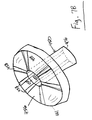
- the cover flange 456 has a central opening 441 and a tube 450 that extends downward from the central opening 441.
- the inner surface 447 of the tube 450 has capillary channels 458 formed in the inner surface 447.
- the capillary channels 458 also are present in the upper surface 449 of the cover flange 456.
- the capillary channels 458 provide a fluid path from the bottom end 476 of the tube 450 to the edge 461 of the cover flange 456.
- the cover flange fits over the open end of the reservoir 440 as shown in Figure 7 such that the tube 460 extends into the liquid bait 42 in the reservoir 440.
- the central opening 441 of the cover flange 456 is sealed by closure 446, preferably a foil material as described above.
- the reservoir 440 is arranged in the insect bait station 410 such that the reservoir opens upwardly and the bottom end of the reservoir 440 rests on the floor of the a liquid bait holding tank 30.
- the insect bait station 410 of Figure 7 also includes an activation member 480 that is used to release liquid bait 42 from the reservoir 440 into the liquid holding tank 30.
- the activation member 480 has a central section 481 having a conical projection 487 that extends downwardly from the central section 481 of the activation member 480. Looking at Figure 7 and Figure 7A, it can be seen that the central section 481 is attached to the activation member 480 by way of a connector strips 482.
- Figure 7 shows the insect bait station 410 with the activation member 480 in the storage position, i.e., the position that would keep the liquid bait 42 in the reservoir 440.
- a user applies a downward force to the central section 481 of the activation member 480 in direction "A" as shown in Figure 7.
- the central section 481 of the activation member 480 moves downward by the way of flexing of the connector strip 482.
- the central section 481 of the activation member 480 continues to move downward such that conical projection 487 punctures the closure 446 above the central opening 441 of the cover flange 456 such that liquid bait 42 may exit the reservoir 440.
- capillary action of the capillary channels 458 transports liquid bait 42 up from the reservoir 440, through the mouth of the reservoir and out onto the upper surface 449 of the cover flange 456.
- a porous material 454, such as a wick is located adjacent the upper surface 449 of the cover flange 456 to assist in transporting liquid bait 42 from the upper surface 449 of the cover flange 456.
- Liquid bait 42 may then travel over the edge 461 of the cover flange 456 and down into the liquid holding tank 30 as shown in Figure 7.
- the liquid bait 42 is then accessible to a crawling insect that enters the opening 28 in the outer wall 22 of the base 22 and the aperture 32 in the inner wall 24 of the base 22. While the ability of an insect to access liquid bait 42 in the liquid bait holding tank 30 is readily apparent, insects can also feed directly from the cover flange 456 and/or the porous material 454. Therefore, the presence of liquid bait 42 in the liquid bait holding tank 30 is not a requirement of the invention as long as an insect can access the cover flange 456 and/or the porous material 454 to feed.
- the base 520 includes a cylindrical inner wall 24 that is inwardly spaced from the outer wall 22 so as to define a solid bait chamber 26 between the outer wall 22 and the inner wall 24.
- the solid bait chamber 26 contains a solid bait 34.
- the inner wall 24 of the base 20 also defines a liquid bait holding tank 30 in an inner region of the base 20.
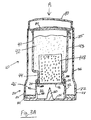
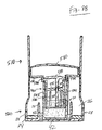
- the insect bait station 510 shown in Figures 8A and 8B also includes a reservoir 540 for holding a liquid bait 42.
- the reservoir 540 has a body 543 that terminates in a mouth 544.
- the mouth 544 is sealed so as to contain the liquid bait 42 in the reservoir 540 by way of a closure 546 that may be a foil material as described above.
- the reservoir 540 rests on and can be affixed to a floor of the liquid bait holding tank 30.
- the insect bait station 510 of Figures 8A and 8B also includes an activation member 580 that is used to release liquid bait 42 from the reservoir 540 into the liquid holding tank 30.
- the activation member 580 has a cylindrical tube 591 that extends downwardly from an underside 584 of the activation member 580.
- a liquid transport device 590 preferably a porous material such as a wick, is contained within the tube 591.
- the tube 591 also has an outer wall 594 with holes 586 such that liquid bait 42 may flow through each hole 586 when the liquid bait 42 is activated as described below.
- the tube 591 also has a transverse wall 587 extending laterally inward from an inner surface 555 of the tube 591.
- the transverse wall 587 defines an upper section and a lower section of the tube 591.
- the porous material 590 extends from the upper section to the lower section of the tube through a passage 577 in the transverse wall 587.
- FIG 8A shows the insect bait station 510 with the activation member 580 in the storage position, i.e., the position that would keep the liquid bait 42 in the reservoir 540.
- a user applies a downward force to the activation member 580 in direction "A" as shown in Figure 8A.
- the activation member 580 moves downward such that tube 591 punctures the closure 546 of the reservoir 540 and enters the reservoir 540 as shown in Figure 8B. Liquid bait 42 can then flow into the inner regions of the tube 591.
- the porous material 590 in the tube 591 transports the liquid bait 42 upward from the tube 591 of the reservoir 540 by capillary or wicking action through the passage 577 in the transverse wall 587 and out of the mouth 544 of the reservoir 540 by way of holes 589 in the tube 591 as shown in Figure 8B.
- the liquid bait 42 travels down the sides of reservoir 540 and into the liquid holding tank 30 as shown in Figure 8B.
- the liquid bait 42 is then accessible to a crawling insect that enters the opening 28 in the outer wall 22 of the base 22 and the aperture 32 in the inner wall 24 of the base 22. While the ability of an insect to access liquid bait 42 in the liquid bait holding tank 30 is readily apparent, insects can also feed directly from the porous material 590. Therefore, the presence of liquid bait 42 in the liquid bait holding tank 30 is not a requirement of the invention as long as an insect can access the porous material 590 to feed.
- the insect bait station of Figure 8A and 8B is particularly advantageous as it will not leak liquid bait from the reservoir 540 upon tipping over even after the liquid bait enters the liquid bait holding tank 30. Looking at Figure 8B, it can be seen that the reservoir is sealed by the tube 591 after activation. If the insect bait station 510 were to tip over, the porous material 590 and the transverse wall 587 of the tube 591 would block passage of liquid bait from the reservoir 540.
- the base 720 includes a cylindrical inner wall 24 that is inwardly spaced from the outer wall 22 so as to define a solid bait chamber 26 between the outer wall 22 and the inner wall 24.
- the solid bait chamber 26 contains a solid bait 34 as described above.
- the inner wall 24 of the base 720 also defines a liquid bait holding tank 30 in an inner region of the base 720.
- the insect bait station 710 shown in Figure 9 also includes a reservoir 740 for holding a liquid bait 42.
- the reservoir 740 has a body 743 with sloping sides that extend upward and terminate in a mouth 744.
- the mouth 744 is sealed so as to contain the liquid bait 42 in the reservoir 740 by way of a closure 746, preferably a foil material as described above.
- the reservoir 740 is arranged in the insect bait station 710 such that the mouth 744 opens upwardly and the bottom end of the reservoir 740 rests on the floor of the a liquid bait holding tank 30.
- the reservoir 740 also includes a liquid transport device 748 that may be a capillary member or other porous material such as a wick.
- the liquid transport device 748 is positioned in the mouth 744 of the reservoir 740.
- the insect bait station 710 of Figure 9 also includes an activation member 780 that is used to release liquid bait 42 from the reservoir 740 into the liquid holding tank 30.
- the activation member 780 has a central section 781 having a conical projection 747 that extends downwardly from the central section 781 of the activation member 280.
- a liquid transport device 790 such a capillary member or other porous material such as a wick, surrounds the projection 747.
- a cylindrical wall 786 also extends downwardly from the central section 781 of the activation member 780 and surrounds the liquid transport device 790. Looking at Figure 9 and Figure 11A, it can be seen that the central section 781 is attached to the activation member 780 by way of connector strips 782, which have an area of reduced thickness 783 in their upper surface.
- Figure 9 shows the insect bait station 710 with the activation member 780 in the storage position, i.e., the position that would keep the liquid bait 42 in the reservoir 740.
- a user applies a downward force to the activation member 780 in direction "A" as shown in Figure 9
- the central section 781 of the activation member 780 moves downward such that the connector strips 782 fracture at their respective areas of reduced thickness 783 in the upper surface.
- the central section 781 of the activation member 780 continues to move downward such that conical projection 747 punctures the closure 746 of the reservoir 740 such that liquid bait 42 may exit the reservoir 740.
- the liquid transport device 748 transports the liquid bait 42 upward from the body 743 of the reservoir 740 by capillary or wicking action through the mouth 744 of the reservoir 740.
- the liquid transport device 790 which is in fluid communication with the liquid transport device 748, then transports the liquid bait 42 from the liquid transport device 748 such that the liquid bait 42 travels down the sloping sides of reservoir 740 and into the liquid holding tank 30 as shown in Figure 9.
- the liquid bait 42 is then accessible to a crawling insect that enters the opening 28 in the outer wall 22 of the base 22 and the aperture 32 in the inner wall 24 of the base 22. While the ability of an insect to access liquid bait 42 in the liquid bait holding tank 30 is readily apparent, insects can also feed directly from the liquid transport device 748 and/or liquid transport device 790. Therefore, the presence of liquid bait 42 in the liquid bait holding tank 30 is not a requirement of the invention as long as an insect can access the liquid transport device 748 and/or liquid transport device 790 to feed.
- the base 820 includes a cylindrical inner wall 24 that is inwardly spaced from the outer wall 22 so as to define a solid bait chamber 26 between the outer wall 22 and the inner wall 24.
- the solid bait chamber 26 contains a solid bait 34 as described above.
- the inner wall 24 of the base 820 also defines a liquid bait holding tank 30 in an inner region of the base 820.
- the insect bait station 810 shown in Figure 10 also includes a reservoir 840 for holding a liquid bait 42.
- the reservoir 840 has a body 843 with sloping sides that extend upward and terminate in a mouth 844.
- the mouth 844 is sealed so as to contain the liquid bait 42 in the reservoir 840 by way of a closure 846, preferably a foil material as described above.
- the reservoir 840 is arranged in the insect bait station 810 such that the mouth 844 opens upwardly and the bottom end of the reservoir 840 rests on the floor of the liquid bait holding tank 30.
- the reservoir 840 also includes a liquid transport device 848 that may be a capillary member or other porous material such as a wick.
- the liquid transport device 848 is positioned in the mouth 844 of the reservoir 840.
- the insect bait station 810 of Figure 10 also includes an activation member 880 that is used to release liquid bait 42 from the reservoir 840 into the liquid holding tank 30.
- the activation member 880 has a central section 881 having a liquid transport device 890, such a capillary member or other porous material such as a wick, that extends downwardly from the central section 881 of the activation member 880.
- a cylindrical wall 886 also extends downwardly from the central section 881 of the activation member 880 and surrounds the liquid transport device 890. Looking at Figure 10 and Figure 11B, it can be seen that the central section 881 is attached to the activation member 880 by way of connector strips 882, which have an area of reduced thickness 883 in their upper surface.
- Figure 10 shows the insect bait station 810 with the activation member 880 in the storage position, i.e., the position that would keep the liquid bait 42 in the reservoir 840.
- a user applies a downward force to the central section 881 of the activation member 880 in direction "A" as shown in Figure 10.
- the central section 881 of the activation member 880 moves downward such that the connector strips 882 fracture at their respective areas of reduced thickness 883 in the upper surface.
- the central section 881 of the activation member 880 continues to move downward such that liquid transport device 890 punctures the closure 846 of the reservoir 840 such that liquid bait 42 may exit the reservoir 840.
- the liquid transport device 848 transports the liquid bait 42 upward from the body 843 of the reservoir 840 by capillary or wicking action through the mouth 844 of the reservoir 840.
- the liquid transport device 890 which is in fluid communication with the liquid transport device 848, then transports the liquid bait 42 from the liquid transport device 848 such that the liquid bait 42 travels down the sloping sides of reservoir 840 and into the liquid holding tank 30 as shown in Figure 10.
- Liquid bait 42 may also travel through openings 887 of the cylindrical wall 886 of the activation member 880 and down the sloping sides of reservoir 840 and into the liquid holding tank 30.
- the liquid bait 42 is then accessible to a crawling insect that enters the opening 28 in the outer wall 22 of the base 22 and the aperture 32 in the inner wall 24 of the base 22. While the ability of an insect to access liquid bait 42 in the liquid bait holding tank 30 is readily apparent, insects can also feed directly from the liquid transport device 848 and/or liquid transport device 890. Therefore, the presence of liquid bait 42 in the liquid bait holding tank 30 is not a requirement of the invention as long as an insect can access the liquid transport device 848 and/or liquid transport device 890 to feed.
- an insect bait station for controlling crawling insects, such as cockroaches.
- Cockroaches are attracted to the insect bait station to find a dark harborage and to seek the moisture offered by the liquid bait. They enter through access openings in the insect bait station and reach areas which contain solid or liquid bait. They then feed upon the bait-toxicant solids and/or liquids, which may preferably contain delayed action insecticide, return to their usual hiding places within walls or behind cabinets and die.
- the dead roaches, which are now toxic, will then be cannibalized by other roaches, extending the kill action of the station to roaches which have not contacted the station directly.
- the invention provides an insecticidal bait station.
Landscapes
- Life Sciences & Earth Sciences (AREA)
- Pest Control & Pesticides (AREA)
- Health & Medical Sciences (AREA)
- General Health & Medical Sciences (AREA)
- Toxicology (AREA)
- Engineering & Computer Science (AREA)
- Insects & Arthropods (AREA)
- Wood Science & Technology (AREA)
- Zoology (AREA)
- Environmental Sciences (AREA)
- Catching Or Destruction (AREA)
- Agricultural Chemicals And Associated Chemicals (AREA)
- Medicines Containing Material From Animals Or Micro-Organisms (AREA)
Abstract
Description
Claims (9)
- An insect bait station, comprising:characterized in that such that the liquid is a liquid bait (42);a reservoir (40) for holding a liquid (42), the reservoir having a mouth (44) and a closure (46) for sealing the mouth (44) such that the liquid (42) is contained in the reservoir (40); there being positioned a liquid wicking device (148) in the mouth (44) of the reservoir (40) to transport the liquid (42) from the reservoir (40) and through the mouth (44) of the reservoir (40); wherein the station also comprises a solid bait;
a piercer is provided for opening the closure (46) of the reservoir (40) such that said transport of liquid may occur;
an activation member (80) is provided for moving the piercer (160) into contact with the closure (46) of the reservoir (40) to open the closure (46); and
the station also comprises an insecticide . - An insect bait station according to claim 1, wherein there is provided a base (20) defining a solid bait chamber containing the solid bait (34).
- An insect bait station according to claim 2, wherein:the base (20) includes an upwardly extending outer wall (22) and an upwardly extending inner wall (24), the inner wall (24) being inwardly spaced from the outer wall (22) so as to define the solid bait chamber (26) between the outer wall (22) and the inner wall (24), the outer wall (22) having an opening (28) to provide access to the solid bait chamber (26), the inner wall (24) also defining a liquid bait holding tank (30) in an inner region of the base which can be fed by the wicking device (148) once the closure (46) is opened.
- An insect bait station according to claim 1, 2 or 3 wherein:the reservoir (40) is positioned such that the mouth (44) of the reservoir (40) opens downwardly, anda downward force applied to the activation member (80) brings the closure (46) of the reservoir (40) into contact with the piercer (160) to open the closure (46).
- An insect bait station according to any preceding claim wherein:the liquid wicking device (143) comprises a porous material positioned in the mouth of the reservoir (40).
- An insect bait station according to any of claims 1, 2 or 3 wherein:the reservoir (240) is positioned such that the mouth (244) of the reservoir opens upwardly, andthe piercer (282) comprises a downwardly extending projection located on an underside of the activation member (280).
- An insect bait station according to any of claims 1, 2 or 3 wherein:the piercer (282) comprises a downwardly extending blade (682) located on the underside of the activation member (680) such that a downward force applied to the activation member (680) brings the blade into contact with the closure (664) of the reservoir (640) to open the closure (664).
- An insect bait station according to any of claims 1 to 3 wherein:the liquid wicking device comprises a tube (450) having an inner surface (447) with capillary channels (458), the tube extending from the mouth of the reservoir into the liquid bait, the capillary channels (458) controllably transporting liquid bait from the reservoir up through the mouth of the reservoir.
- A method of controlling crawling insects, comprising:providing a bait station in accordance with any preceding claim; andlocating the bait station where accessible to the insects.
Applications Claiming Priority (3)
| Application Number | Priority Date | Filing Date | Title |
|---|---|---|---|
| US14218499P | 1999-07-01 | 1999-07-01 | |
| US142184P | 1999-07-01 | ||
| PCT/US2000/018091 WO2001001770A1 (en) | 1999-07-01 | 2000-06-30 | Insecticidal liquid bait station |
Publications (2)
| Publication Number | Publication Date |
|---|---|
| EP1191842A1 EP1191842A1 (en) | 2002-04-03 |
| EP1191842B1 true EP1191842B1 (en) | 2003-01-08 |
Family
ID=22498886
Family Applications (1)
| Application Number | Title | Priority Date | Filing Date |
|---|---|---|---|
| EP00945046A Expired - Lifetime EP1191842B1 (en) | 1999-07-01 | 2000-06-30 | Insecticidal liquid bait station |
Country Status (16)
| Country | Link |
|---|---|
| US (1) | US6553712B1 (en) |
| EP (1) | EP1191842B1 (en) |
| JP (1) | JP2003503077A (en) |
| KR (1) | KR100443187B1 (en) |
| CN (1) | CN1166288C (en) |
| AT (1) | ATE230563T1 (en) |
| AU (1) | AU761063B2 (en) |
| BR (1) | BR0012070A (en) |
| CA (1) | CA2373746C (en) |
| DE (1) | DE60001171T2 (en) |
| ES (1) | ES2185600T3 (en) |
| NZ (1) | NZ516405A (en) |
| PL (1) | PL352759A1 (en) |
| RU (1) | RU2002102493A (en) |
| WO (1) | WO2001001770A1 (en) |
| ZA (1) | ZA200200119B (en) |
Cited By (1)
| Publication number | Priority date | Publication date | Assignee | Title |
|---|---|---|---|---|
| US20210144986A1 (en) * | 2011-06-15 | 2021-05-20 | Ecolab Usa Inc. | Flying insect attraction station |
Families Citing this family (82)
| Publication number | Priority date | Publication date | Assignee | Title |
|---|---|---|---|---|
| US7614568B2 (en) * | 2000-08-24 | 2009-11-10 | Microlin, Llc | Device employing gas generating cell for facilitating controlled release of fluid into ambient environment |
| US20070001024A1 (en) * | 1997-06-20 | 2007-01-04 | Microlin, L.C. | Device employing gas generating cell for facilitating controlled release of fluid into ambient environment |
| US7712248B2 (en) * | 2002-09-20 | 2010-05-11 | The United States Of America As Represented By The Secretary Of Agriculture | Insect attractant releasing device |
| US20050263609A1 (en) * | 2002-11-20 | 2005-12-01 | Joshi Ashok V | Foldable, refillable, sustained-release fluid delivery system |
| US6871444B1 (en) * | 2003-10-06 | 2005-03-29 | Alan Bernard | User activated disposable insect bait station |
| US7584901B2 (en) * | 2003-12-16 | 2009-09-08 | International Flavors & Fragrances, Inc. | Dispensing device for active gels |
| DE102004003439B4 (en) * | 2004-01-22 | 2022-02-03 | Sata Gmbh & Co. Kg | Paint cup system for a paint spray gun |
| DE102004022103A1 (en) * | 2004-05-05 | 2005-11-24 | Bayer Cropscience Ag | Bait Box |
| ATE383768T1 (en) * | 2004-05-11 | 2008-02-15 | Johnson & Son Inc S C | BAIT STATIONS |
| MY146066A (en) * | 2004-07-01 | 2012-06-29 | Microlin L C | Device employing gas generating cell for facilitating controlled release of fluid into ambient environment |
| US7678174B2 (en) * | 2004-09-01 | 2010-03-16 | Sumitomo Electric Industries, Ltd. | Soft magnetic material, compressed powder magnetic core and method for producing compressed power magnetic core |
| CN101052424A (en) * | 2004-09-08 | 2007-10-10 | 日晷公司 | Methods and apparatus for a low-cost vapor-dispersing device |
| USD515175S1 (en) | 2004-10-26 | 2006-02-14 | Senoret Chemical Company | Bait station |
| US7204054B2 (en) * | 2005-02-04 | 2007-04-17 | Senoret Chemical Company | Insecticidal activatable bait station |
| US20070289202A1 (en) * | 2005-07-12 | 2007-12-20 | Spencer Bill L | Method and apparatus for abating insects |
| FR2890053B1 (en) * | 2005-08-31 | 2010-03-19 | Valeo Systemes Thermiques | CAP FOR A CONTAINER COMPRISING A VOLATILE AIR TREATMENT AGENT |
| JP4846436B2 (en) * | 2006-05-10 | 2011-12-28 | アース製薬株式会社 | Pest control container |
| US20090134238A1 (en) * | 2006-06-13 | 2009-05-28 | Biosect Research Ltd. | Reservoir and matrix system for controlled release of insect semiochemicals |
| GB2451585A (en) * | 2006-10-20 | 2009-02-04 | Sdk | A method of applying insecticide to an enclosed space |
| GB2442939A (en) * | 2006-10-20 | 2008-04-23 | Sdk | A method of applying liquid insecticide to an enclosed space |
| DE502007000825D1 (en) | 2006-12-05 | 2009-07-16 | Sata Gmbh & Co Kg | Ventilation for the gravity cup of a paint spray gun |
| US9307820B2 (en) * | 2007-01-04 | 2016-04-12 | Novomic Ltd. | Treating lice with gaseous compounds in an airtight space |
| US20100031556A1 (en) * | 2007-01-08 | 2010-02-11 | Km Investors, Llc | Device and method for controlling insect pests |
| US8113390B2 (en) * | 2007-04-18 | 2012-02-14 | Microlin, Llc | Gas generation dispenser apparatus and method for on-demand fluid delivery |
| KR100911534B1 (en) | 2007-05-14 | 2009-08-10 | 주식회사 세스코 | Cockroach trap |
| US8005350B2 (en) * | 2007-05-24 | 2011-08-23 | Pestco, Inc. | Gravity driven fluid supply vessel for dispensing an aromatic odor neutralizer |
| US7922104B2 (en) * | 2007-05-24 | 2011-04-12 | Pestco, Inc. | Gravity driven fluid supply vessel for dispensing an aromatic odor neutralizer |
| AU2008352594B2 (en) | 2008-03-12 | 2013-11-21 | Jeffrey D. Fox | Disposable spray gun cartridge |
| MX2010010586A (en) | 2008-04-04 | 2010-10-20 | Basf Se | Device for controlling pests. |
| US8342177B2 (en) * | 2008-09-24 | 2013-01-01 | Covidien Lp | Spill resistant humidifier for use in a breathing assistance system |
| DE202008014389U1 (en) | 2008-10-29 | 2010-04-08 | Sata Gmbh & Co. Kg | Gravity cup for a paint spray gun |
| US20100176214A1 (en) * | 2009-01-13 | 2010-07-15 | Joshi Ashok V | Greeting card fragrance delivery system |
| US9468204B2 (en) | 2009-03-04 | 2016-10-18 | Goodnature Limited | Trap |
| CA2662816C (en) | 2009-04-16 | 2011-01-25 | The Procter & Gamble Company | Method for delivering a volatile material |
| CA2759008C (en) | 2009-04-16 | 2014-06-03 | The Procter & Gamble Company | Volatile composition dispenser |
| US11911540B2 (en) | 2009-04-16 | 2024-02-27 | The Procter & Gamble Company | Apparatus for delivering a volatile material |
| US8740110B2 (en) | 2009-04-16 | 2014-06-03 | The Procter & Gamble Company | Apparatus for delivering a volatile material |
| JP5213058B2 (en) * | 2009-06-30 | 2013-06-19 | 株式会社吉野工業所 | Volatilization vessel for volatilization liquid |
| DE102009032399A1 (en) | 2009-07-08 | 2011-01-13 | Sata Gmbh & Co. Kg | Spray Gun |
| MX2012002754A (en) * | 2009-09-03 | 2012-04-30 | Fmc Corp | Bed bug capturing device. |
| US9272065B2 (en) * | 2009-10-02 | 2016-03-01 | Takasago International Corporation | Volatile medium delivery device |
| DE202010007355U1 (en) | 2010-05-28 | 2011-10-20 | Sata Gmbh & Co. Kg | Nozzle head for a spraying device |
| US20120066960A1 (en) * | 2010-09-22 | 2012-03-22 | Pryor Alan E | Bait Station |
| US9333519B2 (en) | 2010-12-02 | 2016-05-10 | Sata Gmbh & Co. Kg | Spray gun and accessories |
| US8939435B2 (en) | 2011-06-03 | 2015-01-27 | Microlin, Llc | Device for delivery of volatile liquids to gaseous environment utilizing a gas generating cell |
| CN103517765B (en) | 2011-06-30 | 2017-09-12 | 萨塔有限两合公司 | Easy-to-clean spray gun, accessories for the spray gun and methods of mounting and dismounting |
| US20130180162A1 (en) * | 2012-01-17 | 2013-07-18 | Bug Elimination And Prevention Corporation | Bed bug trap, carbon dioxide generator, and travel kit |
| AU2012258328B2 (en) | 2012-08-30 | 2017-10-05 | Goodnature Limited | Animal traps and trigger mechanisms |
| US9238086B2 (en) * | 2012-10-16 | 2016-01-19 | Silver Coast, Inc. | Spill-resistant air freshener canister |
| BR112015032985A2 (en) * | 2013-07-01 | 2017-08-22 | Takasago Int Corporation U S A | FRAGRANCE DELIVERY SYSTEM, FRAGRANCE DELIVERY DEVICE AND METHOD FOR OPERATING A FRAGRANCE DELIVERY SYSTEM |
| CA155474S (en) | 2013-09-27 | 2015-08-27 | Sata Gmbh & Co Kg | Spray gun |
| USD822191S1 (en) | 2013-10-16 | 2018-07-03 | Silver Coast, Inc. | Refill for a fragrance dispenser |
| DE202013105779U1 (en) | 2013-12-18 | 2015-03-19 | Sata Gmbh & Co. Kg | Air nozzle termination for a paint spray gun |
| US9015989B1 (en) | 2014-05-22 | 2015-04-28 | Bell Laboratories, Inc. | Ant bait dispenser |
| CN105289870B (en) | 2014-07-31 | 2019-09-24 | 萨塔有限两合公司 | Manufacturing method of spray gun, spray gun, spray gun body and cover |
| CA159961S (en) | 2014-07-31 | 2015-07-17 | Sata Gmbh & Co Kg | Spray gun |
| USD758537S1 (en) | 2014-07-31 | 2016-06-07 | Sata Gmbh & Co. Kg | Paint spray gun rear portion |
| US10225925B2 (en) | 2014-08-29 | 2019-03-05 | Nxp Usa, Inc. | Radio frequency coupling and transition structure |
| USD768820S1 (en) | 2014-09-03 | 2016-10-11 | Sata Gmbh & Co. Kg | Paint spray gun with pattern |
| US10182565B2 (en) * | 2015-02-20 | 2019-01-22 | Sterling International Inc. | Insect repellent fixture and method |
| DE102015006484A1 (en) | 2015-05-22 | 2016-11-24 | Sata Gmbh & Co. Kg | Nozzle arrangement for a spray gun, in particular paint spray gun and spray gun, in particular paint spray gun |
| DE102015016474A1 (en) | 2015-12-21 | 2017-06-22 | Sata Gmbh & Co. Kg | Air cap and nozzle assembly for a spray gun and spray gun |
| DE102016109930A1 (en) * | 2016-05-30 | 2017-11-30 | Jürgen Buchstaller | Device for holding a bait |
| KR20190067154A (en) * | 2016-07-20 | 2019-06-14 | 마커스 아자렐로 | Pest control system and method |
| CN205995666U (en) | 2016-08-19 | 2017-03-08 | 萨塔有限两合公司 | Spray gun and its trigger |
| CN205966208U (en) | 2016-08-19 | 2017-02-22 | 萨塔有限两合公司 | Hood subassembly and spray gun |
| MX2020000030A (en) * | 2017-06-30 | 2020-08-06 | Scotts Canada Ltd | An insect trap. |
| US10166311B1 (en) * | 2017-10-19 | 2019-01-01 | F-Matic, Inc. | Twist activated dispenser |
| DE102018118737A1 (en) | 2018-08-01 | 2020-02-06 | Sata Gmbh & Co. Kg | Nozzle for a spray gun, nozzle set for a spray gun, spray guns and method for producing a nozzle for a spray gun |
| DE102018118738A1 (en) | 2018-08-01 | 2020-02-06 | Sata Gmbh & Co. Kg | Base body for a spray gun, spray guns, spray gun set, method for producing a base body for a spray gun and method for converting a spray gun |
| CN112533705B (en) | 2018-08-01 | 2023-07-04 | 萨塔有限两合公司 | Nozzle bank for spray gun, spray gun system, method for manufacturing nozzle modules, method for selecting nozzle modules from nozzle banks for painting tasks, selection system and computer program product |
| DE102018122004A1 (en) | 2018-09-10 | 2020-03-12 | Sata Gmbh & Co. Kg | Spray gun, material application system and method for its operation |
| ES2752884B2 (en) * | 2018-10-05 | 2021-03-10 | Zenit Estudio De Diseno E Innovacion S L | COMPOSITE INSECT BAIT |
| ES2818773B2 (en) * | 2019-10-09 | 2022-01-31 | Zobele Espana Sa | Volatile substance diffusion device |
| ES2818748B2 (en) * | 2019-10-09 | 2022-03-22 | Zobele Espana Sa | Volatile substance diffusion device |
| ES2937019T3 (en) * | 2019-11-19 | 2023-03-23 | Zobele Holding Spa | Volatile substance diffusion device |
| US11432540B1 (en) * | 2020-02-25 | 2022-09-06 | Dalen Products, Inc. | Mosquito trap |
| DE102020106172A1 (en) | 2020-03-06 | 2021-09-09 | Sata Gmbh & Co. Kg | Spray gun, in particular paint spray gun that atomizes compressed air, in particular hand-held paint spray gun that atomizes compressed air |
| DE102020109914A1 (en) * | 2020-04-08 | 2021-10-14 | Sata Gmbh & Co. Kg | Color cup with ventilation valve |
| DE102020123769A1 (en) | 2020-09-11 | 2022-03-17 | Sata Gmbh & Co. Kg | Sealing element for sealing a transition between a base body of a spray gun and an add-on part of a spray gun, add-on part, in particular paint nozzle arrangement, for a spray gun and spray gun, in particular paint spray gun |
| KR102441289B1 (en) * | 2020-10-12 | 2022-09-07 | (주) 디엔디이 | Feeding device for fish farm and feeding method using the same |
| US12433288B2 (en) * | 2022-03-02 | 2025-10-07 | Laurie Weddington | Systems, devices, and/or methods for managing pest control |
Family Cites Families (22)
| Publication number | Priority date | Publication date | Assignee | Title |
|---|---|---|---|---|
| US1309606A (en) | 1919-07-15 | Rat and mottse exterminator | ||
| US2167978A (en) | 1933-08-02 | 1939-08-01 | Jennerich Balthasar | Insect trap |
| US3587968A (en) * | 1969-07-07 | 1971-06-28 | Ciba Geigy Corp | Apparatus for the diffusion of volatile products |
| US3727840A (en) | 1971-08-19 | 1973-04-17 | Gillette Co | Dispersant container and dispenser |
| DE2807424C2 (en) | 1978-02-22 | 1980-05-14 | Globol-Werk Gmbh, 8858 Neuburg | Evaporation device for insecticides and / or other volatile agents |
| US4323193A (en) * | 1979-11-07 | 1982-04-06 | The Procter & Gamble Company | Wick-type slow diffusion dispenser |
| DE3364412D1 (en) * | 1982-05-15 | 1986-08-14 | Globol Werk | Vaporizer for insecticides, aromatics and/or other volatile active substances |
| ES279748Y (en) * | 1984-05-11 | 1988-05-01 | Airwick Ag | DEVICE TO PROVIDE A VOLATILE PRODUCT |
| US4823506A (en) | 1987-07-02 | 1989-04-25 | S.C. Johnson & Son, Inc. | Insect bait device |
| US4837969A (en) | 1988-09-27 | 1989-06-13 | S. C. Johnson & Son, Inc. | Bait station |
| US5038516A (en) | 1990-03-20 | 1991-08-13 | Carl Doucette | Rodent poison dispenser |
| US5033229A (en) | 1990-10-10 | 1991-07-23 | S. C. Johnson & Son, Inc. | Liquid delivery bait station |
| US5339563A (en) | 1991-01-22 | 1994-08-23 | Frank Job | Non-toxic insect capture and killing apparatus |
| BR9307358A (en) * | 1992-11-03 | 1999-06-15 | Ronpal Ltd | Insecticidal device |
| WO1994022297A1 (en) | 1993-04-05 | 1994-10-13 | The Clorox Company | Multiple component pest control systems |
| US5501033A (en) | 1994-05-02 | 1996-03-26 | S. C. Johnson & Son, Inc. | Two-stage liquid delivery bait station |
| US5548922A (en) | 1995-01-11 | 1996-08-27 | S. C. Johnson & Son, Inc. | Insect bait station |
| US5628143A (en) | 1995-06-14 | 1997-05-13 | Doucette; Carl | Rodent poison dispenser |
| US5802761A (en) | 1996-09-18 | 1998-09-08 | S. C. Johnson & Son, Inc. | Bait station for crawling insects |
| US5960585A (en) | 1996-09-18 | 1999-10-05 | S. C. Johnson & Son, Inc. | Bait station for crawling insects |
| US5749168A (en) | 1996-10-10 | 1998-05-12 | Chrysanthis; Chris A. | Fly and insect trap |
| US5875968A (en) * | 1997-07-18 | 1999-03-02 | S. C. Johnson & Son, Inc. | Liquid air freshener dispenser device with nonporous capillary wicking function |
-
2000
- 2000-06-30 JP JP2001507287A patent/JP2003503077A/en active Pending
- 2000-06-30 NZ NZ516405A patent/NZ516405A/en unknown
- 2000-06-30 EP EP00945046A patent/EP1191842B1/en not_active Expired - Lifetime
- 2000-06-30 BR BR0012070-7A patent/BR0012070A/en not_active IP Right Cessation
- 2000-06-30 ES ES00945046T patent/ES2185600T3/en not_active Expired - Lifetime
- 2000-06-30 CN CNB008111715A patent/CN1166288C/en not_active Expired - Fee Related
- 2000-06-30 RU RU2002102493/13A patent/RU2002102493A/en not_active Application Discontinuation
- 2000-06-30 AT AT00945046T patent/ATE230563T1/en not_active IP Right Cessation
- 2000-06-30 KR KR10-2001-7016954A patent/KR100443187B1/en not_active Expired - Fee Related
- 2000-06-30 WO PCT/US2000/018091 patent/WO2001001770A1/en not_active Ceased
- 2000-06-30 PL PL00352759A patent/PL352759A1/en not_active Application Discontinuation
- 2000-06-30 CA CA002373746A patent/CA2373746C/en not_active Expired - Fee Related
- 2000-06-30 AU AU59041/00A patent/AU761063B2/en not_active Ceased
- 2000-06-30 DE DE60001171T patent/DE60001171T2/en not_active Expired - Fee Related
- 2000-06-30 US US10/069,153 patent/US6553712B1/en not_active Expired - Fee Related
-
2002
- 2002-01-07 ZA ZA200200119A patent/ZA200200119B/en unknown
Cited By (2)
| Publication number | Priority date | Publication date | Assignee | Title |
|---|---|---|---|---|
| US20210144986A1 (en) * | 2011-06-15 | 2021-05-20 | Ecolab Usa Inc. | Flying insect attraction station |
| US20240423186A1 (en) * | 2011-06-15 | 2024-12-26 | Ecolab Usa Inc. | Flying insect attraction station |
Also Published As
| Publication number | Publication date |
|---|---|
| DE60001171T2 (en) | 2003-07-10 |
| WO2001001770A1 (en) | 2001-01-11 |
| RU2002102493A (en) | 2003-08-27 |
| EP1191842A1 (en) | 2002-04-03 |
| KR100443187B1 (en) | 2004-08-04 |
| JP2003503077A (en) | 2003-01-28 |
| US6553712B1 (en) | 2003-04-29 |
| CA2373746A1 (en) | 2001-01-11 |
| BR0012070A (en) | 2002-04-30 |
| DE60001171D1 (en) | 2003-02-13 |
| ZA200200119B (en) | 2003-01-07 |
| CN1166288C (en) | 2004-09-15 |
| WO2001001770A9 (en) | 2002-07-25 |
| ES2185600T3 (en) | 2003-05-01 |
| KR20020026485A (en) | 2002-04-10 |
| CA2373746C (en) | 2006-08-29 |
| CN1367645A (en) | 2002-09-04 |
| AU761063B2 (en) | 2003-05-29 |
| AU5904100A (en) | 2001-01-22 |
| WO2001001770B1 (en) | 2001-02-08 |
| PL352759A1 (en) | 2003-09-08 |
| ATE230563T1 (en) | 2003-01-15 |
| NZ516405A (en) | 2002-11-26 |
Similar Documents
| Publication | Publication Date | Title |
|---|---|---|
| CA2373746C (en) | Insecticidal liquid bait station | |
| EP1638767B1 (en) | Bait stations | |
| EP0552248B1 (en) | Liquid delivery bait station | |
| US8266839B2 (en) | Insect bait station with snap-open cartridge and cradle | |
| AU2003275010B9 (en) | Wick-based delivery system with wick having sections of varying porosities | |
| EP1133323B1 (en) | Unit for the transfer and distribution of a liquid, dispenser and refill | |
| US6871444B1 (en) | User activated disposable insect bait station | |
| US20080104882A1 (en) | Insect bait station | |
| JPH10512146A (en) | Insect feeding ground | |
| IL103629A (en) | Insecticidal device |
Legal Events
| Date | Code | Title | Description |
|---|---|---|---|
| PUAI | Public reference made under article 153(3) epc to a published international application that has entered the european phase |
Free format text: ORIGINAL CODE: 0009012 |
|
| 17P | Request for examination filed |
Effective date: 20020102 |
|
| AK | Designated contracting states |
Kind code of ref document: A1 Designated state(s): AT BE CH CY DE DK ES FI FR GB GR IE IT LI LU MC NL PT SE |
|
| AX | Request for extension of the european patent |
Free format text: AL;LT;LV;MK;RO;SI |
|
| GRAG | Despatch of communication of intention to grant |
Free format text: ORIGINAL CODE: EPIDOS AGRA |
|
| GRAG | Despatch of communication of intention to grant |
Free format text: ORIGINAL CODE: EPIDOS AGRA |
|
| GRAH | Despatch of communication of intention to grant a patent |
Free format text: ORIGINAL CODE: EPIDOS IGRA |
|
| 17Q | First examination report despatched |
Effective date: 20020628 |
|
| GRAH | Despatch of communication of intention to grant a patent |
Free format text: ORIGINAL CODE: EPIDOS IGRA |
|
| GRAA | (expected) grant |
Free format text: ORIGINAL CODE: 0009210 |
|
| AK | Designated contracting states |
Kind code of ref document: B1 Designated state(s): AT BE CH CY DE DK ES FI FR GB GR IE IT LI LU MC NL PT SE |
|
| PG25 | Lapsed in a contracting state [announced via postgrant information from national office to epo] |
Ref country code: FI Free format text: LAPSE BECAUSE OF FAILURE TO SUBMIT A TRANSLATION OF THE DESCRIPTION OR TO PAY THE FEE WITHIN THE PRESCRIBED TIME-LIMIT Effective date: 20030108 Ref country code: CH Free format text: LAPSE BECAUSE OF FAILURE TO SUBMIT A TRANSLATION OF THE DESCRIPTION OR TO PAY THE FEE WITHIN THE PRESCRIBED TIME-LIMIT Effective date: 20030108 Ref country code: NL Free format text: LAPSE BECAUSE OF FAILURE TO SUBMIT A TRANSLATION OF THE DESCRIPTION OR TO PAY THE FEE WITHIN THE PRESCRIBED TIME-LIMIT Effective date: 20030108 Ref country code: GR Free format text: LAPSE BECAUSE OF FAILURE TO SUBMIT A TRANSLATION OF THE DESCRIPTION OR TO PAY THE FEE WITHIN THE PRESCRIBED TIME-LIMIT Effective date: 20030108 Ref country code: LI Free format text: LAPSE BECAUSE OF FAILURE TO SUBMIT A TRANSLATION OF THE DESCRIPTION OR TO PAY THE FEE WITHIN THE PRESCRIBED TIME-LIMIT Effective date: 20030108 Ref country code: BE Free format text: LAPSE BECAUSE OF FAILURE TO SUBMIT A TRANSLATION OF THE DESCRIPTION OR TO PAY THE FEE WITHIN THE PRESCRIBED TIME-LIMIT Effective date: 20030108 Ref country code: AT Free format text: LAPSE BECAUSE OF FAILURE TO SUBMIT A TRANSLATION OF THE DESCRIPTION OR TO PAY THE FEE WITHIN THE PRESCRIBED TIME-LIMIT Effective date: 20030108 |
|
| REF | Corresponds to: |
Ref document number: 230563 Country of ref document: AT Date of ref document: 20030115 Kind code of ref document: T |
|
| REG | Reference to a national code |
Ref country code: GB Ref legal event code: FG4D |
|
| REG | Reference to a national code |
Ref country code: CH Ref legal event code: EP |
|
| REG | Reference to a national code |
Ref country code: IE Ref legal event code: FG4D |
|
| REF | Corresponds to: |
Ref document number: 60001171 Country of ref document: DE Date of ref document: 20030213 Kind code of ref document: P |
|
| PG25 | Lapsed in a contracting state [announced via postgrant information from national office to epo] |
Ref country code: SE Free format text: LAPSE BECAUSE OF FAILURE TO SUBMIT A TRANSLATION OF THE DESCRIPTION OR TO PAY THE FEE WITHIN THE PRESCRIBED TIME-LIMIT Effective date: 20030408 Ref country code: DK Free format text: LAPSE BECAUSE OF FAILURE TO SUBMIT A TRANSLATION OF THE DESCRIPTION OR TO PAY THE FEE WITHIN THE PRESCRIBED TIME-LIMIT Effective date: 20030408 |
|
| REG | Reference to a national code |
Ref country code: ES Ref legal event code: FG2A Ref document number: 2185600 Country of ref document: ES Kind code of ref document: T3 |
|
| PGFP | Annual fee paid to national office [announced via postgrant information from national office to epo] |
Ref country code: PT Payment date: 20030616 Year of fee payment: 4 |
|
| PG25 | Lapsed in a contracting state [announced via postgrant information from national office to epo] |
Ref country code: CY Free format text: LAPSE BECAUSE OF FAILURE TO SUBMIT A TRANSLATION OF THE DESCRIPTION OR TO PAY THE FEE WITHIN THE PRESCRIBED TIME-LIMIT Effective date: 20030630 Ref country code: LU Free format text: LAPSE BECAUSE OF NON-PAYMENT OF DUE FEES Effective date: 20030630 Ref country code: MC Free format text: LAPSE BECAUSE OF NON-PAYMENT OF DUE FEES Effective date: 20030630 Ref country code: IE Free format text: LAPSE BECAUSE OF NON-PAYMENT OF DUE FEES Effective date: 20030630 |
|
| REG | Reference to a national code |
Ref country code: CH Ref legal event code: PL |
|
| ET | Fr: translation filed | ||
| PLBE | No opposition filed within time limit |
Free format text: ORIGINAL CODE: 0009261 |
|
| STAA | Information on the status of an ep patent application or granted ep patent |
Free format text: STATUS: NO OPPOSITION FILED WITHIN TIME LIMIT |
|
| 26N | No opposition filed |
Effective date: 20031009 |
|
| REG | Reference to a national code |
Ref country code: IE Ref legal event code: MM4A |
|
| PG25 | Lapsed in a contracting state [announced via postgrant information from national office to epo] |
Ref country code: PT Free format text: LAPSE BECAUSE OF NON-PAYMENT OF DUE FEES Effective date: 20041231 |
|
| REG | Reference to a national code |
Ref country code: PT Ref legal event code: MM4A Free format text: LAPSE DUE TO NON-PAYMENT OF FEES Effective date: 20041231 |
|
| PGFP | Annual fee paid to national office [announced via postgrant information from national office to epo] |
Ref country code: DE Payment date: 20080731 Year of fee payment: 9 |
|
| PGFP | Annual fee paid to national office [announced via postgrant information from national office to epo] |
Ref country code: GB Payment date: 20080627 Year of fee payment: 9 |
|
| PGFP | Annual fee paid to national office [announced via postgrant information from national office to epo] |
Ref country code: ES Payment date: 20090626 Year of fee payment: 10 |
|
| PGFP | Annual fee paid to national office [announced via postgrant information from national office to epo] |
Ref country code: FR Payment date: 20090617 Year of fee payment: 10 |
|
| GBPC | Gb: european patent ceased through non-payment of renewal fee |
Effective date: 20090630 |
|
| PGFP | Annual fee paid to national office [announced via postgrant information from national office to epo] |
Ref country code: IT Payment date: 20090627 Year of fee payment: 10 |
|
| PG25 | Lapsed in a contracting state [announced via postgrant information from national office to epo] |
Ref country code: GB Free format text: LAPSE BECAUSE OF NON-PAYMENT OF DUE FEES Effective date: 20090630 |
|
| PG25 | Lapsed in a contracting state [announced via postgrant information from national office to epo] |
Ref country code: DE Free format text: LAPSE BECAUSE OF NON-PAYMENT OF DUE FEES Effective date: 20100101 |
|
| REG | Reference to a national code |
Ref country code: FR Ref legal event code: ST Effective date: 20110228 |
|
| PG25 | Lapsed in a contracting state [announced via postgrant information from national office to epo] |
Ref country code: IT Free format text: LAPSE BECAUSE OF NON-PAYMENT OF DUE FEES Effective date: 20100630 |
|
| PG25 | Lapsed in a contracting state [announced via postgrant information from national office to epo] |
Ref country code: FR Free format text: LAPSE BECAUSE OF NON-PAYMENT OF DUE FEES Effective date: 20100630 |
|
| REG | Reference to a national code |
Ref country code: ES Ref legal event code: FD2A Effective date: 20110715 |
|
| PG25 | Lapsed in a contracting state [announced via postgrant information from national office to epo] |
Ref country code: ES Free format text: LAPSE BECAUSE OF NON-PAYMENT OF DUE FEES Effective date: 20110705 |
|
| PG25 | Lapsed in a contracting state [announced via postgrant information from national office to epo] |
Ref country code: ES Free format text: LAPSE BECAUSE OF NON-PAYMENT OF DUE FEES Effective date: 20100701 |