EP1191824A2 - Electronic ballast for fluorescent lamp - Google Patents
Electronic ballast for fluorescent lamp Download PDFInfo
- Publication number
- EP1191824A2 EP1191824A2 EP01660174A EP01660174A EP1191824A2 EP 1191824 A2 EP1191824 A2 EP 1191824A2 EP 01660174 A EP01660174 A EP 01660174A EP 01660174 A EP01660174 A EP 01660174A EP 1191824 A2 EP1191824 A2 EP 1191824A2
- Authority
- EP
- European Patent Office
- Prior art keywords
- lamp
- cathodes
- primary winding
- heating
- voltage
- Prior art date
- Legal status (The legal status is an assumption and is not a legal conclusion. Google has not performed a legal analysis and makes no representation as to the accuracy of the status listed.)
- Withdrawn
Links
Images


Classifications
-
- H—ELECTRICITY
- H05—ELECTRIC TECHNIQUES NOT OTHERWISE PROVIDED FOR
- H05B—ELECTRIC HEATING; ELECTRIC LIGHT SOURCES NOT OTHERWISE PROVIDED FOR; CIRCUIT ARRANGEMENTS FOR ELECTRIC LIGHT SOURCES, IN GENERAL
- H05B41/00—Circuit arrangements or apparatus for igniting or operating discharge lamps
- H05B41/14—Circuit arrangements
- H05B41/26—Circuit arrangements in which the lamp is fed by power derived from DC by means of a converter, e.g. by high-voltage DC
- H05B41/28—Circuit arrangements in which the lamp is fed by power derived from DC by means of a converter, e.g. by high-voltage DC using static converters
- H05B41/295—Circuit arrangements in which the lamp is fed by power derived from DC by means of a converter, e.g. by high-voltage DC using static converters with semiconductor devices and specially adapted for lamps with preheating electrodes, e.g. for fluorescent lamps
Definitions
- the present invention relates to an electronic ballast for a fluorescent lamp, the ballast comprising
- This kind of a ballast is known from patent publication EP 589 081 B1.
- This prior-art ballast provides the heating current to a first cathode of the lamp by means of connecting the cathode in series with the components of the resonant circuit.
- the heating current of the second cathode is generated by means of a secondary winding of the cathode current sense transformer.
- a switch in parallel with the primary winding of a current sense/drive transformer so that different sensitivities can be selected for current sense.
- This prior-art ballast circuitry has no facility for cutting off the heating current of lamp cathodes either when the lamp strikes or just before the ignition of the lamp, but instead depending on the implementation of the circuitry, more or less cathode current remains to flow in one or both cathodes even after the lamp strikes.
- Another shortcoming is that the heating currents of the cathodes are out of balance with each other, whereby the sensing thereof as well as the cathode current control based on the sensed cathode current become complicated. Also the wear of cathodes is uneven.
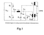
- switches S 1 and S 2 form the normal half-bridge of a lamp circuit.
- Capacitor C DC1 blocks the DC component of the lamp drive voltage.
- Inductor L R and capacitor C R serve as the conventional resonant circuit used for striking the lamp.
- the lamp is stabilized to a desired intensity level by way of controlling the operating frequency of the half-bridge totem-pole connected switch transistors S 1 and S 2 .
- the above-described conventional ballast circuit is complemented with a transformer T 1 whose primary winding T 1a is connected in series with a resonant-circuit capacitor C R . Also in series with the primary winding T 1a of the transformer is connected a capacitor C DC2 . In parallel with the capacitor C DC2 and the primary winding of transformer T 1 is connected a switch transistor S 3 . In parallel with transistor S 3 is a diode D 1 that may be integral with the switch component as in a MOSFET switch or a discrete component. The secondary windings T 1b and T 1c of the transformer are connected in parallel with the lamp cathodes.
- auxiliary components capacitors, diodes, etc.
- the lamp load circuit branches via a conductor from the common point of the resonant-circuit components, that is, inductor L R and capacitor C R to the other lamp cathode, from this branching point onward the lamp ignition circuit and lamp load circuit are in a parallel connection.
- the drive current to the fluorescent lamp cathodes can be sensed at the transformer primary winding T 1a .
- the drive voltage to the fluorescent lamp cathodes may also be sensed from the voltage over the transformer primary winding T 1a . Sensing of drive voltage and current at both cathodes separately is not necessary inasmuch the cathode drive circuit is self-regulating so that when the resistance of the hotter cathode increases, the colder cathode receives more current. Failure at one cathode can be detected from a significant change at the transformer primary winding.
- Changes in the resistance of the fluorescent lamp cathodes during heating can be sensed by way of sensing both the drive current to the cathodes and the drive voltage to the cathodes in the beginning of the heating cycle and then comparing the resistance value obtained based on these values with the corresponding values sensed and computed during heating.
- FIG. 2 is shown the voltage waveform measured from the common point between the resonant-circuit inductor L R and capacitor C R to the ground potential of the supply voltage during a typical preheating cycle.
- FIG. 3 is shown typical voltage waveforms over the primary winding T 1a and secondary winding T 1b of transformer T 1 during the preheating cycle when the cathode resistance is low.
- FIG. 4 shows the corresponding situation for a high cathode resistance.
- the primary voltage is clipped by both diodes D 1 and D 2 .
- the circuit configuration according to the invention may be utilized particularly advantageously for controlling the heating current of lamp cathodes.
- the heating current can be adjusted to a desired level by driving switch S 3 ON and OFF with a pulse-width-controlled drive signal.
- the operating frequency of switch S 3 can be synchronized to the lamp operating frequency.
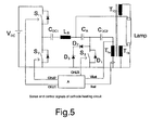
- FIG. 5 is shown by way of an exemplary embodiment the sense/control arrangement during the preheating cycle and immediately thereafter.
- a control block A can sense the cathode drive voltage Vkat during the preheating cycle.
- the voltage over the lamp cathodes can be sensed from the primary winding of transformer T 1 inasmuch the same voltage waveform appears over the different windings of the transformed scaled in turns ratio of the windings.
- the control block A incorporates a circuit or a stored program, wherein a limit is set for the drive voltages of the cathodes at which they are assumed to have reached a sufficiently high temperature for striking the lamp. When this limit is attained, control block A opens switch S 3 via control line OHJ3 thus terminating the preheating cycle. Thereupon, the control block commences the ignition cycle by controlling the operating frequency of switches S 1 and S 2 so that the voltage generated by the resonant circuit L R1 , C R rises to a level sufficient for striking the lamp.
- Control block A incorporates a circuit or stored program capable of resolving the resistance of the cathodes from the sensed values. During the preheating cycle, control block A can then determine from the sensed values the instant of a sufficiently high increase of the cathode resistance to allow the control block A to terminate the preheating cycle. As the resistances of the cathodes are proportional to their temperatures, the ignition cycle can be commenced by the ballast as soon as the cathodes have reached their proper striking temperatures.
- the common heating current of the cathodes can be either sensed separately from transformer current or inferred by the logic of the control block from control frequency of the switches S 1 and S 2 and the known values of the resonant-circuit components C R and L R and the input voltage.
- FIG. 6 is elucidated how the sensed values obtained according to the invention and the control functions based thereon can be used in a controllable ballast at low levels of illumination.
- the heating voltage applied to the cathodes can be kept at a constant level by way of sensing the voltage Vkat over the transformer primary winding and then based thereon controlling the ON time of S 3 .
- the control can be effected dynamically pulse by pulse.
- FIG. 6 is shown at two control levels the voltage waveform over the transformer primary winding (upper diagrams) and the corresponding control signals of switch S 3 (lower diagrams).
Landscapes
- Circuit Arrangements For Discharge Lamps (AREA)
Abstract
Description
- an inverter which is supplied from a DC voltage source and includes two power switch elements operating in a half-bridge totem-pole configuration for generating a high-frequency voltage,
- a lamp load circuit which is connected to the inverter and comprises an inductor and a capacitor that in a series connection form a series-resonant circuit and to which the fluorescent lamp can be connected, and
- a heating circuit of the fluorescent lamp cathodes, the heating circuit including a transformer having a primary winding connected in series with the capacitor of the resonant circuit and secondary windings connected in parallel with the cathodes of the fluorescent lamp,
- FIG. 1
- shows a circuit diagram elucidating an electronic ballast according to the invention as to its basic components;
- FIG. 2
- shows a plot of the voltage at the common point of the resonant circuit capacitor and inductor referenced to the ground potential of the supply voltage during the preheating cycle;
- FIG. 3
- shows a plot of the primary and secondary voltages of transformer T1 for a low cathode resistance;
- FIG. 4
- shows a plot of the primary and secondary voltages of transformer T1 for a high cathode resistance;
- FIG. 5
- shows the circuit diagram of FIG. 1 complemented with the sense and control signals of cathode heating circuit and a control block (A) suited for receiving, handling and transmitting signals, whereby the embodiment illustrated in FIG. 5 differs from that of FIG. 1 only therein that capacitor CDC2 has been moved to the other end of the primary winding T1a of transformer T1; and
- FIG. 6
- shows at two different power control levels the voltage over primary winding T1a of transformer T1 (upper diagrams) and the control signals of switch S3 connected over the winding (lower diagrams).
Claims (8)
- An electronic ballast for a fluorescent lamp, the ballast comprisingcharacterized in that the heating current drive to the lamp cathodes is arranged to take place via said secondary windings (T1b, T1c) such that each of the lamp cathodes is driven by its own secondary winding, and that in parallel with said primary winding (T1a) is disposed a switch element (S3) whose setting in an ON condition shuts off the heating current passed via said secondary windings (T1b, T1c).an inverter supplied from a DC voltage source (VDC) and including two power switch elements (S1, S2) in a half-bridge totem-pole configuration for generating a high-frequency voltage,a lamp load circuit which is connected to the inverter and comprising an inductor (LR) and a capacitor (CR) in a series connection so as to form a series-resonant circuit and to which circuit the fluorescent lamp can be connected, anda heating circuit of the fluorescent lamp cathodes, the heating circuit including a transformer having a primary winding (T1a) in series with the capacitor (CR) of the resonant circuit and at least two secondary windings (T1b, T1c) connected in parallel with the cathodes of the fluorescent lamp, the lamp being adapted connectable in parallel with the series connection of the capacitor (CR) of the resonant circuit and the transformer primary winding (T1a),
- A ballast according to claim 1, characterized in that the heating current is adapted controllable to a desired level by driving the switch (S3) ON and OFF with a pulse-width-controlled drive signal.
- A ballast according to claim 2, characterized in that the operating frequency of switch (S3) is synchronized to the operating frequency of lamp load circuit.
- A ballast according to any one of claims 1 - 3, characterized in that the sensing of the drive current (Ikat) to the fluorescent lamp cathodes is arranged to take place at the primary winding (T1a) of the transformer.
- A ballast according to any one of claims 1 - 4, characterized in that the sensing of the drive voltage (Vkat) to the fluorescent lamp cathodes is arranged to take place from voltage of the primary winding (T1a) of the transformer.
- A ballast according to claims 4 and 5, characterized in that the sensing of changes in the resistance of the fluorescent lamp cathodes during heating cycle is arranged to take place by way of sensing both the drive current of the cathodes and the drive voltage of the cathodes in the beginning of the heating cycle and then comparing the resistance value obtained based on these values with the corresponding values sensed and computed during heating.
- A ballast according to any one of claims 1 - 6, characterized in that, in order to limit the cathode drive voltage, in parallel with the primary winding (T1a) of the transformer are connected components (D2, D3) for clipping the positive half-wave of the voltage.
- A ballast according to any one of claims 1-7, characterized in that the heating current drive to the lamp cathodes is arranged to take place solely via said secondary windings (T1b, T1c).
Applications Claiming Priority (2)
| Application Number | Priority Date | Filing Date | Title |
|---|---|---|---|
| FI20002069A FI108105B (en) | 2000-09-20 | 2000-09-20 | Electronic connection arrangement for a fluorescent tube |
| FI20002069 | 2000-09-20 |
Publications (2)
| Publication Number | Publication Date |
|---|---|
| EP1191824A2 true EP1191824A2 (en) | 2002-03-27 |
| EP1191824A3 EP1191824A3 (en) | 2003-12-17 |
Family
ID=8559118
Family Applications (1)
| Application Number | Title | Priority Date | Filing Date |
|---|---|---|---|
| EP01660174A Withdrawn EP1191824A3 (en) | 2000-09-20 | 2001-09-19 | Electronic ballast for fluorescent lamp |
Country Status (2)
| Country | Link |
|---|---|
| EP (1) | EP1191824A3 (en) |
| FI (1) | FI108105B (en) |
Cited By (4)
| Publication number | Priority date | Publication date | Assignee | Title |
|---|---|---|---|---|
| EP1811817A1 (en) | 2006-01-18 | 2007-07-25 | Helvar Oy Ab | Electronic ballast for fluorescent lamp |
| WO2007099464A1 (en) | 2006-02-28 | 2007-09-07 | Koninklijke Philips Electronics N.V. | Method and device for driving a discharge lamp |
| WO2010150151A2 (en) | 2009-06-24 | 2010-12-29 | Koninklijke Philips Electronics N.V. | Electronic ballast for a fluorescent lamp |
| WO2011114245A1 (en) * | 2010-03-19 | 2011-09-22 | Koninklijke Philips Electronics N.V. | Electronic ballast for parallel lamp operation with program start |
Family Cites Families (2)
| Publication number | Priority date | Publication date | Assignee | Title |
|---|---|---|---|---|
| US5656891A (en) * | 1994-10-13 | 1997-08-12 | Tridonic Bauelemente Gmbh | Gas discharge lamp ballast with heating control circuit and method of operating same |
| BE1009717A3 (en) * | 1995-10-20 | 1997-07-01 | Philips Electronics Nv | Shifting. |
-
2000
- 2000-09-20 FI FI20002069A patent/FI108105B/en not_active IP Right Cessation
-
2001
- 2001-09-19 EP EP01660174A patent/EP1191824A3/en not_active Withdrawn
Cited By (5)
| Publication number | Priority date | Publication date | Assignee | Title |
|---|---|---|---|---|
| EP1811817A1 (en) | 2006-01-18 | 2007-07-25 | Helvar Oy Ab | Electronic ballast for fluorescent lamp |
| WO2007099464A1 (en) | 2006-02-28 | 2007-09-07 | Koninklijke Philips Electronics N.V. | Method and device for driving a discharge lamp |
| WO2010150151A2 (en) | 2009-06-24 | 2010-12-29 | Koninklijke Philips Electronics N.V. | Electronic ballast for a fluorescent lamp |
| WO2011114245A1 (en) * | 2010-03-19 | 2011-09-22 | Koninklijke Philips Electronics N.V. | Electronic ballast for parallel lamp operation with program start |
| CN102792781A (en) * | 2010-03-19 | 2012-11-21 | 皇家飞利浦电子股份有限公司 | Electronic ballast for parallel lamp operation with program start |
Also Published As
| Publication number | Publication date |
|---|---|
| EP1191824A3 (en) | 2003-12-17 |
| FI20002069A0 (en) | 2000-09-20 |
| FI108105B (en) | 2001-11-15 |
Similar Documents
| Publication | Publication Date | Title |
|---|---|---|
| US6972531B2 (en) | Method for operating at least one low-pressure discharge lamp | |
| US5424611A (en) | Method for pre-heating a gas-discharge lamp | |
| US6181082B1 (en) | Ballast power control circuit | |
| US5650694A (en) | Lamp controller with lamp status detection and safety circuitry | |
| EP0233605B1 (en) | Frequency modulation ballast circuit | |
| CN100591187C (en) | Integrated Circuits for Luminaire Heating and Dimming Control | |
| US6127786A (en) | Ballast having a lamp end of life circuit | |
| US5656891A (en) | Gas discharge lamp ballast with heating control circuit and method of operating same | |
| US7190151B2 (en) | High intensity discharge lamp ballast circuit | |
| EP0836793B1 (en) | Power supply for feeding and igniting a discharge lamp | |
| US6479949B1 (en) | Power regulation circuit for high frequency electronic ballast for ceramic metal halide lamp | |
| EP1987705B1 (en) | Voltage fed inverter for fluorescent lamps | |
| CA2512449A1 (en) | Ballast with filament heating control circuit | |
| JP2005510834A (en) | Discharge lamp electrode heating device | |
| US7560868B2 (en) | Ballast with filament heating and ignition control | |
| US6864642B2 (en) | Electronic ballast with DC output flyback converter | |
| US6232726B1 (en) | Ballast scheme for operating multiple lamps | |
| US6414449B1 (en) | Universal electronic ballast | |
| EP2452544B1 (en) | Fluorescent ballast with inherent end-of-life protection | |
| US6157142A (en) | Hid ballast circuit with arc stabilization | |
| WO2000045622A1 (en) | Hid ballast with hot restart circuit | |
| EP2283704B1 (en) | Voltage fed programmed start ballast | |
| US7977894B1 (en) | Programmed start ballast for gas discharge lamps | |
| EP0759685A2 (en) | Instant lighting type fluorescent lamp lighting circuit | |
| US20100013401A1 (en) | Circuit Arrangement and Method for Starting and Operating One or More Discharge Lamps |
Legal Events
| Date | Code | Title | Description |
|---|---|---|---|
| PUAI | Public reference made under article 153(3) epc to a published international application that has entered the european phase |
Free format text: ORIGINAL CODE: 0009012 |
|
| AK | Designated contracting states |
Kind code of ref document: A2 Designated state(s): AT BE CH CY DE DK ES FI FR GB GR IE IT LI LU MC NL PT SE TR |
|
| AX | Request for extension of the european patent |
Free format text: AL;LT;LV;MK;RO;SI |
|
| PUAL | Search report despatched |
Free format text: ORIGINAL CODE: 0009013 |
|
| AK | Designated contracting states |
Kind code of ref document: A3 Designated state(s): AT BE CH CY DE DK ES FI FR GB GR IE IT LI LU MC NL PT SE TR |
|
| AX | Request for extension of the european patent |
Extension state: AL LT LV MK RO SI |
|
| AKX | Designation fees paid | ||
| REG | Reference to a national code |
Ref country code: DE Ref legal event code: 8566 |
|
| STAA | Information on the status of an ep patent application or granted ep patent |
Free format text: STATUS: THE APPLICATION IS DEEMED TO BE WITHDRAWN |
|
| 18D | Application deemed to be withdrawn |
Effective date: 20040618 |