EP1191715A2 - Optical wireless network with direct optical beam pointing - Google Patents
Optical wireless network with direct optical beam pointing Download PDFInfo
- Publication number
- EP1191715A2 EP1191715A2 EP01000449A EP01000449A EP1191715A2 EP 1191715 A2 EP1191715 A2 EP 1191715A2 EP 01000449 A EP01000449 A EP 01000449A EP 01000449 A EP01000449 A EP 01000449A EP 1191715 A2 EP1191715 A2 EP 1191715A2
- Authority
- EP
- European Patent Office
- Prior art keywords
- light
- transmitter
- receiver
- mirror
- lens
- Prior art date
- Legal status (The legal status is an assumption and is not a legal conclusion. Google has not performed a legal analysis and makes no representation as to the accuracy of the status listed.)
- Withdrawn
Links
- 230000003287 optical effect Effects 0.000 title abstract description 29
- 230000006854 communication Effects 0.000 claims description 55
- 238000004891 communication Methods 0.000 claims description 55
- 238000000034 method Methods 0.000 claims description 4
- 239000002178 crystalline material Substances 0.000 claims 1
- 230000004044 response Effects 0.000 abstract description 7
- 238000005516 engineering process Methods 0.000 description 8
- 230000005540 biological transmission Effects 0.000 description 6
- 238000013459 approach Methods 0.000 description 5
- 230000008901 benefit Effects 0.000 description 5
- 239000000835 fiber Substances 0.000 description 5
- 238000010276 construction Methods 0.000 description 4
- 239000000463 material Substances 0.000 description 3
- 238000012986 modification Methods 0.000 description 3
- 230000004048 modification Effects 0.000 description 3
- 238000005457 optimization Methods 0.000 description 3
- 230000007175 bidirectional communication Effects 0.000 description 2
- 238000012937 correction Methods 0.000 description 2
- 238000001514 detection method Methods 0.000 description 2
- 230000001105 regulatory effect Effects 0.000 description 2
- XUIMIQQOPSSXEZ-UHFFFAOYSA-N Silicon Chemical compound [Si] XUIMIQQOPSSXEZ-UHFFFAOYSA-N 0.000 description 1
- 239000000853 adhesive Substances 0.000 description 1
- 230000001070 adhesive effect Effects 0.000 description 1
- 229910052782 aluminium Inorganic materials 0.000 description 1
- XAGFODPZIPBFFR-UHFFFAOYSA-N aluminium Chemical compound [Al] XAGFODPZIPBFFR-UHFFFAOYSA-N 0.000 description 1
- 230000000712 assembly Effects 0.000 description 1
- 238000000429 assembly Methods 0.000 description 1
- 230000008859 change Effects 0.000 description 1
- 230000001427 coherent effect Effects 0.000 description 1
- 238000010586 diagram Methods 0.000 description 1
- 235000019800 disodium phosphate Nutrition 0.000 description 1
- 230000000694 effects Effects 0.000 description 1
- 238000004880 explosion Methods 0.000 description 1
- PCHJSUWPFVWCPO-UHFFFAOYSA-N gold Chemical compound [Au] PCHJSUWPFVWCPO-UHFFFAOYSA-N 0.000 description 1
- 229910052737 gold Inorganic materials 0.000 description 1
- 239000010931 gold Substances 0.000 description 1
- 238000009434 installation Methods 0.000 description 1
- 238000012423 maintenance Methods 0.000 description 1
- 238000005259 measurement Methods 0.000 description 1
- 229910052751 metal Inorganic materials 0.000 description 1
- 239000002184 metal Substances 0.000 description 1
- 229910021421 monocrystalline silicon Inorganic materials 0.000 description 1
- 238000002310 reflectometry Methods 0.000 description 1
- 238000010845 search algorithm Methods 0.000 description 1
- 230000008054 signal transmission Effects 0.000 description 1
- 229910052710 silicon Inorganic materials 0.000 description 1
- 239000010703 silicon Substances 0.000 description 1
- 238000010408 sweeping Methods 0.000 description 1
Images


Classifications
-
- H—ELECTRICITY
- H04—ELECTRIC COMMUNICATION TECHNIQUE
- H04B—TRANSMISSION
- H04B10/00—Transmission systems employing electromagnetic waves other than radio-waves, e.g. infrared, visible or ultraviolet light, or employing corpuscular radiation, e.g. quantum communication
- H04B10/11—Arrangements specific to free-space transmission, i.e. transmission through air or vacuum
- H04B10/112—Line-of-sight transmission over an extended range
- H04B10/1121—One-way transmission
-
- H—ELECTRICITY
- H04—ELECTRIC COMMUNICATION TECHNIQUE
- H04B—TRANSMISSION
- H04B10/00—Transmission systems employing electromagnetic waves other than radio-waves, e.g. infrared, visible or ultraviolet light, or employing corpuscular radiation, e.g. quantum communication
- H04B10/11—Arrangements specific to free-space transmission, i.e. transmission through air or vacuum
- H04B10/112—Line-of-sight transmission over an extended range
- H04B10/1123—Bidirectional transmission
-
- H—ELECTRICITY
- H04—ELECTRIC COMMUNICATION TECHNIQUE
- H04B—TRANSMISSION
- H04B10/00—Transmission systems employing electromagnetic waves other than radio-waves, e.g. infrared, visible or ultraviolet light, or employing corpuscular radiation, e.g. quantum communication
- H04B10/11—Arrangements specific to free-space transmission, i.e. transmission through air or vacuum
- H04B10/112—Line-of-sight transmission over an extended range
- H04B10/1123—Bidirectional transmission
- H04B10/1125—Bidirectional transmission using a single common optical path
-
- H—ELECTRICITY
- H04—ELECTRIC COMMUNICATION TECHNIQUE
- H04B—TRANSMISSION
- H04B10/00—Transmission systems employing electromagnetic waves other than radio-waves, e.g. infrared, visible or ultraviolet light, or employing corpuscular radiation, e.g. quantum communication
- H04B10/11—Arrangements specific to free-space transmission, i.e. transmission through air or vacuum
- H04B10/114—Indoor or close-range type systems
- H04B10/1141—One-way transmission
Definitions
- This invention is related to the field of optical wireless communications, and is more specifically directed to the directing of light beams with micromirror assemblies as used in such communications.
- Each of these conventional communications facilities involves certain limitations in their deployment.
- highspeed data transmission such as that provided by digital subscriber line (DSL) services
- DSL digital subscriber line
- communications over "wired" networks including the telephone network, cable network, or dedicated network, requires the running of the physical wires among the locations to be served. This physical installation and maintenance is costly, as well as limiting to the user of the communications network.
- Wireless communication facilities overcome the limitation of physical wires and cabling, and provide great flexibility to the user.
- Conventional wireless technologies involve their own limitations, however.
- the frequencies at which communications may be carried out are regulated and controlled; furthermore, current wireless telephone communication of large data blocks, such as video, is prohibitively expensive, considering the per-unit-time charges for wireless services.
- wireless telephone communications are subject to interference among the various users within the nearby area. Radio frequency data communication must also be carried out within specified frequencies, and is also vulnerable to interference from other transmissions. Satellite transmission is also currently expensive, particularly for bi-directional communications (i.e., beyond the passive reception of television programming).
- a relatively new technology that has been proposed for data communications is the optical wireless network.
- data is transmitted by way of modulation of a light beam, in much the same manner as in the case of fiber optic telephone communications.
- a photoreceiver receives the modulated light, and demodulates the signal to retrieve the data.
- this approach does not use a physical wire for transmission of the light signal.
- a line-of-sight relationship between the transmitter and the receiver permits a modulated light beam, such as that produced by a laser, to travel without the waveguide of the fiber optic.
- high frequency light can provide high bandwidth, for example ranging from on the order of 100Mbps to several Gbps, using conventional technology.
- This high bandwidth need not be shared among users, when carried out over line-of-sight optical communications between transmitters and receivers. Without the other users on the link, of course, the bandwidth is not limited by interference from other users, as in the case of wireless telephony.
- Modulation can also be quite simple, as compared with multiple-user communications that require time or code multiplexing of multiple communications. Bi-directional communication can also be readily carried out according to this technology.
- optical frequencies are not currently regulated, and as such no licensing is required for the deployment of extra-premises networks.
- optical wireless communications may be useful in data communication within a room, such as for communicating video signals from a computer to a display device, such as a video projector.
- a copending United States patent application having the assigned serial number 09/310,284, filed May 12, 1999, and entitled "Optical Switching Apparatus”, discloses a micromirror assembly for directing a light beam in an optical switching apparatus.
- the micromirror reflects the light beam in a manner that may be precisely controlled by electrical signals.
- the micromirror assembly includes a silicon mirror capable of rotating in two axes.
- One or more small magnets are attached to the micromirror itself; a set of four coil drivers are arranged in quadrants, and are current-controlled to attract or repel the micromirror magnets as desired, to tilt the micromirror in the desired direction.
- the directed light beam or laser beam
- precise positioning of the mirror to aim the beam at the desired receiver is essential in establishing communication. It is contemplated that this precision positioning be accomplished by way of calibration and feedback, so that the mirror is able to sense its position and make corrections.
- the present application discloses a system and method that provide an optical wireless receiver that can provide direct feedback to the transmitter regarding its aiming position. Such a receiver may provide such feedback passively.
- the present application yet further discloses a transmitter and receiver system that provides feedback to the transmitter without requiring a secondary communications channel.
- the present invention may be implemented into an optical wireless network by providing a receiver lens surrounded by a reflective annulus.
- the annulus is preferably formed of a retro-reflector, such as corner cubes, to reflect a directed light beam back to the transmitter over a wide range of angles of incidence.
- the present invention eliminates the need for a secondary feedback communications channel.
- Figure 1 is a schematic drawing of an optical wireless network using a micromirror assembly, and in which a secondary feedback channel is provided.
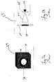
- Figures 2a and 2b are perspective and cross-sectional views, respectively, of a receiver in the optical wireless network.
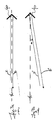
- Figures 3a and 3b are cross-sectional views illustrating the operation of corner cube elements.
- Figure 4 is a schematic diagram illustrating the construction of a transmitter in the optical wireless network.
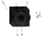
- Figure 5 is a perspective view of the receiver of Figures 2a and 2b illustrating the operation of a preferred embodiment of the invention.
- computer 2 is a conventional microprocessor based personal computer or workstation, including the appropriate network interface adapter for outputting the data to be communicated.
- computer 2 may include a 100Base-T to 100Base-FX converter, coupled to a laser driver that generates modulated control signals that are then applied to transmitter optical module 5, which aims a directed light beam at the desired receiver 17, and which modulates the light beam to communicate the data.
- the transmitting source may be a network switch or router, a source of video data such as a DVD player or a television set-top converter box, or the like, rather than computer 2 as shown. It is contemplated that the present invention may be used in connection with effectively any source of digital data.
- transmitter optical module 5 includes modulating laser 6, which generates a collimated coherent light beam of the desired wavelength (e.g., 850 nm) and power (e.g., on the order of 4 to 5 ⁇ W/cm 2 measured at 50 meters, with a spot size of on the order of 2.0 to 2.5 mm in diameter).
- Modulating laser 6 modulates this light beam according to the digital data being transmitted, in response to the laser driver driven by computer 2.
- the modulation scheme used preferably follows a conventional data communications standard, such as those used in connection with fiber optic communications for similar networks.
- the modulated laser beam exits modulating laser 6 and is reflected from micromirror assembly 10 toward receiver 17.
- micromirror assembly 10 includes a mirror element formed of a single piece of material, preferably single-crystal silicon, photolithographically etched in the desired pattern, to integrally form the mirror surface 29, and its supporting hinges, gimbals, and frame.
- the mirror surface is preferably plated with a metal, such as gold or aluminum.
- One or more permanent magnets are then attached to the mirror and gimbals, to enable rotation of the mirror in the desired direction in response to a magnetic field generated by nearby coil driver magnets to which currents of the desired magnitude and polarity are applied.
- receiver 17 captures the incoming directed light beam, and converts the modulated light energy to an electrical signal; for example, receiver 17 includes a photodiode that modulates an electrical signal in response to the intensity of detected light. The output of this photodiode is then amplified as necessary, and converted into a conventional network protocol, such as by way of a 100Base-FX to 100Base-T converter. Such other conventional receiver circuitry, such as demodulators, filters, and the like, are also provided. The demodulated communicated electrical signal is then forwarded from receiver 17 to router 18, and thus into the receiving network, for eventual distribution to server 20, in this example.
- this example illustrates a unidirectional, or simplex, communications approach, for ease of this description. It will be appreciated by those skilled in the art that bi-directional, or duplex, communications may be carried out by providing another transmitter-receiver pair for communicating signals in the opposite direction (router 18 to computer 2).
- the communications arrangement of Figure 1 may be utilized in connection with a wide range of applications, beyond the simple computer-to-network example suggested by Figure 1.
- each of multiple computers in an office or other workspace may communicate with one another and with a larger network by way of modulated light to a central receiver within the room, and also between rooms by way of relayed communications along hallways or in a space frame.
- Other indoor applications for this optical wireless communications may include the communication of video signals from a computer or DVD player to a large-screen projector. It is further contemplated that optical wireless communications in this fashion may be carried out in this manner but on a larger scale, for example between or among buildings.
- micromirror assembly 10 must be precisely controlled to aim the modulated laser beam at receiver 17, and thus optimize the signal-to-noise ratio of the transmitted signals. It is contemplated that this precision positioning is preferably accomplished by way of calibration and feedback, so that the mirror is able to sense its position and make corrections.
- receiver 17 applies a signal indicative of the received signal intensity to secondary feedback transmitter 25.
- Secondary feedback transmitter 25 then provides a secondary feedback signal SFB to control circuitry 14 of transmitter optical module 5.
- the medium of secondary feedback signal SFB can be any one of a number of conventional communications media, considering that the bandwidth requirements of secondary feedback signal SFB are very low.
- This signal may be communicated by a radio signal in order to maintain the network as fully wireless, or alternatively over a telephone line or other hardwired connection.
- the secondary feedback communications channel will generally not be a high bandwidth link, considering that the optical wireless network itself is being used to establish such high bandwidth communications.
- the reflected laser beam impinges beam splitter 12.
- Beam splitter 12 transmits the majority of the energy to receiver 17, but reflects a portion of the energy to position sensitive detector (PSD) 15.
- PSD 15 provides signals to control circuitry 14, indicating the position of the reflected light that it receives.
- Control circuitry 14 then issues control signals to micromirror assembly 10 to direct its angle of reflection in response to the signals from PSD 15 and in response to the secondary feedback signal SFB from transmitter 25 at the receiver end, thus optimizing the aim of the directed laser beam at receiver 17.
- micromirror assembly 10 and PSD 15 "sweep" the aim of the directed laser beam across the general area of receiver 17.
- receiver 17 issues the secondary feedback signal SFB to control circuitry 14 according to the received energy over time.
- These "pings” may be compared with the instantaneous position of micromirror assembly 10 as measured by PSD 15, to calibrate and optimize the aim of micromirror assembly 10 to achieve maximum energy transmission. Once this aim is set, communications may then be carried out. It is contemplated, however, that adjustments may be necessary due to external factors such as building or equipment movement and the like. These adjustments may be carried out by way of feedback from receiver 17 (either over the secondary channel or as transmit mode feedback in a duplex arrangement), or by periodically repeating the measurement and sweeping.
- receiver 27 As shown in the perspective view of Figure 2a, receiver 27 is embodied in housing 31. On the side of housing 31 that is to receive the incident light from the transmitter, lens 28 is surrounded by reflector ring 30 in this embodiment of the invention. Lens 28 is a conventional lens for receiving and focusing the directed light beam from the transmitter. As such, the aim of the transmitted beam is optimally directed coaxially with lens 28. As shown in the cross-sectional view of receiver 27 illustrated in Figure 2b, light passing through lens 28 is collected by collection cone 32 to impact photodiode 34, which modulates an electrical signal according to the intensity of the light that it receives. Narrow-band filter 35 is provided at photodiode 34, to filter undesired wavelength light from that received by photodiode 34.
- reflector ring 30 surrounds lens 28.
- reflector ring 30 reflects incident light back to the transmitter as direct optical feedback of the aim of the transmitted light. For example, if the incident light has a spot size that is approximately the size of the outer diameter of reflector ring 30, the light reflected from reflector ring 30 will be at a maximum amplitude when the incident light beam is properly centered coaxially with lens 28.
- the transmitter may include the necessary photodetection capability to receive the reflected light as feedback.
- Reflector ring 30 is constructed of conventional "corner cubes" or “retro-reflectors", so that incident light reflected from reflector ring 30 is directed back at its source, over a wide range of angles of incidence. Corner cubes and retro-reflectors are well known for reflecting light back to its source; examples of these devices include reflectors for bicycles and other vehicles, traffic signs, reflective clothing, and the like.
- Figures 3a and 3b illustrate the principle of operation of a corner cube element 40. As shown in Figures 3a and 3b, corner cube element 40 has perpendicular reflective surfaces, with a center line C/L defined at their vertex and extending at equal 45° angles therefrom.
- Figure 3a illustrates the example of incident light I traveling parallel to center line C/L; incident light I reflects from both perpendicular surfaces of element 40, and with reflected light R traveling along a line that is also parallel to center line C/L.
- incident light I' travels along a line that is at an angle ⁇ from center line C/L.
- this incident light I' reflects from the two perpendicular surfaces back toward the source, with reflected light R' also following angle ⁇ , parallel to incident light I'.
- corner cube element 40 reflects incident light back toward its source.
- reflector ring 30 is the only necessary change at the receiver end of the network. Considering the extremely low cost of corner cube material, the present invention may be readily implemented at the receiver end of the network.
- Transmitter module 45 provides the functions of modulating and transmitting the light data beam to receiver 27 of Figures 2a and 2b, and of receiving reflected light from receiver 27 as positional feedback.
- transmitter module 45 includes laser 36 which generates a directed collimated light beam that is modulated according to the desired data signal.
- the modulation of the laser beam is accomplished simply by switching laser 36 on and off; alternatively, a separate modulator may be interposed after laser 36 in transmitter 45.
- the modulated laser beam passes through lens 38 to expand the size of the beam to correspond to the size of reflector ring 30 at receiver 27. This beam is then aimed by mirror 42 toward receiver 27, as incident light beam I. Because of the corner cubes of reflector ring 30 that reflect light back toward its source, reflected light R returns to transmitter module 45.
- Transmitter module 45 may include a receive side.
- Lens 44 is disposed near mirror 42.
- Collector cone 46 is disposed to receive light from lens 44, and to direct this light through narrow-band filter 47 to photodiode 48.
- Photodiode 48 modulates an electrical signal according to the intensity of light that it receives, through lens 44 and filter 47 in this case.
- Preamplifier 50 amplifies the signal modulated by photodiode 48, and applies this signal to digital signal processor (DSP) 52.
- DSP 52 which is preferably a relatively high performance programmable digital signal processor device such as the 320C5x and 320C6x families of DSPs available from Texas Instruments Incorporated, analyzes the signal from preamplifier 50 and controls the aim of mirror 42 accordingly.
- lens 38 may spread the modulated laser beam to have a spot size that is on the order of the outer diameter of reflector ring 30.
- An example of incident light I having such a spot size is illustrated in Figure 5.
- incident light I irradiates lens 28, but its aim is not optimized since incident light I is not concentric with lens 28.
- Reflective ring 30 will, in this example, reflect light back to transmitter 45.
- the intensity of the reflected light R will not be at a maximum, however, because portions of reflective ring 30 are not illuminated by incident light I.
- the signal received by transmitter 45 via lens 44 and photodiode 48 is applied to DSP 52 and recorded.
- DSP 52 then follows a search algorithm to adjust the aim of mirror 42, and thus the location of incident light I at receiver 27.
- DSP 52 can scan the aim of mirror 42 and follow a maximization algorithm based upon the amplitude of the reflected light R received by photodiode 48. Such maximization will eventually result in mirror 42 being aimed so that incident light I is substantially concentric with lens 28, as this will provide the maximum intensity of reflected light R.
- DSP 52 would search for a minimum reflected light R intensity that is present between two maxima of this intensity; the maxima would be detected when the incident light I impinges reflector ring 30 on any side of lens 28, with the local minimum therebetween occurring with incident light I being substantially centered on lens 28.
- the present invention provides numerous important advantages in the transmission of signals over an optical wireless network.
- the necessary feedback and control of the aim of the transmitting beam is provided without requiring a secondary feedback communications channel.
- the latency of the feedback is greatly reduced, since the feedback is direct and traveling at the speed of light.
- the present invention may be implemented at relatively low cost, especially at the receiver end, with the feedback signal generated in a completely passive manner.
- the optics necessary for the present invention are relatively simple, as are the optimization algorithms for aiming the mirror. It is therefore contemplated that the present invention will provide improved aiming performance at less cost and better performance.
Landscapes
- Physics & Mathematics (AREA)
- Electromagnetism (AREA)
- Engineering & Computer Science (AREA)
- Computer Networks & Wireless Communication (AREA)
- Signal Processing (AREA)
- Optical Communication System (AREA)
Abstract
Description
Claims (9)
- A communications system, comprising:a transmitter comprising: a light source for generating a directed light beam modulated to transmit a data signal; a controllable mirror for directing the light beam toward a receiver; a photodiode for receiving light reflected from substantially the same direction as the light is directed by the mirror; and control circuitry coupled to the photodiode and the mirror for controlling the aim of the mirror; anda receiver comprising: a photodiode for receiving incident light from the transmitter through a lens; and a reflective ring surrounding the lens for reflecting incident light from the transmitter back to the transmitter.
- The system of claim 1, wherein the mirror comprises:a mirror element formed from a single piece of crystalline material, the mirror element having a frame, a mirror surface, and a plurality of hinges.
- The system of claim 1 or claim 2, wherein the reflective ring comprises a plurality of corner cube elements.
- The system of any preceding claim, wherein the light source comprises a laser.
- The system of claim 4, wherein the transmitter further comprises:a lens for spreading the modulated laser beam to have a spot size approximately the same size as an outer diameter of the reflective ring.
- A transmitter for use in the communication system of any of claims 1 to 5.
- A receiver for use in the communication system of any of claims 1 to 5.
- A method of transmitting data signals, comprising:generating a modulated light beam;orienting a micromirror to reflect the modulated light beam toward a receiver;receiving reflected light from the transmitter; andadjusting the orientation of the micromirror responsive to the received reflected light.
- The method of claim 8, wherein the adjusting step comprises:iteratively adjusting the orientation of the micromirror to maximize the intensity of the received reflected light.
Applications Claiming Priority (2)
| Application Number | Priority Date | Filing Date | Title |
|---|---|---|---|
| US23408100P | 2000-09-20 | 2000-09-20 | |
| US234081P | 2000-09-20 |
Publications (2)
| Publication Number | Publication Date |
|---|---|
| EP1191715A2 true EP1191715A2 (en) | 2002-03-27 |
| EP1191715A3 EP1191715A3 (en) | 2004-09-22 |
Family
ID=22879826
Family Applications (1)
| Application Number | Title | Priority Date | Filing Date |
|---|---|---|---|
| EP01000449A Withdrawn EP1191715A3 (en) | 2000-09-20 | 2001-09-12 | Optical wireless network with direct optical beam pointing |
Country Status (4)
| Country | Link |
|---|---|
| US (1) | US20020033982A1 (en) |
| EP (1) | EP1191715A3 (en) |
| JP (1) | JP2002152140A (en) |
| CN (1) | CN1356784A (en) |
Cited By (4)
| Publication number | Priority date | Publication date | Assignee | Title |
|---|---|---|---|---|
| EP1566902A1 (en) * | 2004-02-21 | 2005-08-24 | EADS Space Transportation GmbH | Method of energy transmission using coherent electromagnetic radiation |
| WO2007038023A1 (en) * | 2005-09-28 | 2007-04-05 | Motorola Inc. | Light pad charger for electronic devices |
| CN109640196A (en) * | 2018-11-26 | 2019-04-16 | 中国人民解放军国防科技大学 | A wireless optical communication link reconfigurable system for data center |
| WO2024083562A1 (en) | 2022-10-20 | 2024-04-25 | Signify Holding B.V. | Method for beam alignment in optical wireless communication systems |
Families Citing this family (12)
| Publication number | Priority date | Publication date | Assignee | Title |
|---|---|---|---|---|
| FI20020702A7 (en) | 2002-02-22 | 2003-08-23 | Mikko Kalervo Vaeaenaenen | Wireless broadband communication method and device |
| US20030219251A1 (en) * | 2002-04-10 | 2003-11-27 | Mcmurry Sam Eric | Wireless optical system and method for point-to-point high bandwidth communications |
| US20040069742A1 (en) * | 2002-06-19 | 2004-04-15 | Pan Shaoher X. | Fabrication of a reflective spatial light modulator |
| US20030234994A1 (en) * | 2002-06-19 | 2003-12-25 | Pan Shaoher X. | Reflective spatial light modulator |
| DE10329459A1 (en) * | 2003-07-01 | 2005-01-20 | Marconi Communications Gmbh | Transmitter for an optical message signal |
| US7068417B2 (en) * | 2004-07-28 | 2006-06-27 | Miradia Inc. | Method and apparatus for a reflective spatial light modulator with a flexible pedestal |
| WO2006046087A1 (en) * | 2004-10-26 | 2006-05-04 | Freewire Communications Limited | Diverging beam optical communication system |
| KR101479783B1 (en) * | 2008-09-01 | 2015-01-08 | 삼성전자주식회사 | METHOD AND APPARATUS FOR ALIGNING COMMUNICATION LINKS USING A REFLECTOR |
| CN102193182B (en) * | 2011-04-28 | 2013-07-24 | 中国科学院自动化研究所 | Moveable reflector laser collimator, moveable reflector target surface sensor and laser collimating method thereof |
| US20140133152A1 (en) * | 2012-11-12 | 2014-05-15 | Ge Aviation Systems Llc | Pointing system for a laser |
| NL2032214B1 (en) * | 2022-06-17 | 2024-01-05 | Univ Eindhoven Tech | Bi-directional all-optical wireless communication system with autonomous optical beam steering. |
| WO2025057502A1 (en) * | 2023-09-13 | 2025-03-20 | 住友電気工業株式会社 | Optical power supply system and light projection module |
Family Cites Families (15)
| Publication number | Priority date | Publication date | Assignee | Title |
|---|---|---|---|---|
| US3566126A (en) * | 1967-11-29 | 1971-02-23 | Sylvania Electric Prod | Acquisition and tracking laser communication system |
| DE2453077B2 (en) * | 1974-11-08 | 1976-09-02 | Precitronic Gesellschaft für Feinmechanik und Electronic mbH, 2000 Hamburg | RECEIVING TRANSMITTER DEVICE FOR THE TRANSMISSION OF INFORMATION USING CONCENTRATED, MODULATED LIGHT BEAMS |
| US3989942A (en) * | 1974-12-13 | 1976-11-02 | International Telephone And Telegraph Corporation | Retro-reflecting laser responser and data modulator |
| EP0287032B1 (en) * | 1987-04-13 | 1996-02-28 | Nec Corporation | Optical alignment system |
| US5142400A (en) * | 1989-12-26 | 1992-08-25 | Cubic Corporation | Method and apparatus for automatic acquisition and alignment of an optical beam communication link |
| US5627669A (en) * | 1991-11-13 | 1997-05-06 | Canon Kabushiki Kaisha | Optical transmitter-receiver |
| CA2150127A1 (en) * | 1992-11-25 | 1994-06-09 | Robert E. Hefner, Jr. | Thermosettable composition containing mesogenic moieties |
| US5835458A (en) * | 1994-09-09 | 1998-11-10 | Gemfire Corporation | Solid state optical data reader using an electric field for routing control |
| JPH11136190A (en) * | 1997-10-24 | 1999-05-21 | Canon Inc | Optical space communication device |
| SE509209C2 (en) * | 1997-11-28 | 1998-12-14 | Spectra Precision Ab | Device and method for determining the position of the machining part |
| US6118131A (en) * | 1998-05-11 | 2000-09-12 | Astro Terra Corporation | Directional optics for a system for directing a laser beam toward an active area |
| US6577421B1 (en) * | 1999-08-12 | 2003-06-10 | Hughes Electronics Corporation | Alignment system and method for optical satellite communication |
| US20030043435A1 (en) * | 2001-08-27 | 2003-03-06 | Oettinger Eric Gregory | Method and apparatus for re-acquisition after link disruption in an optical wireless link |
| US20020181055A1 (en) * | 2001-04-20 | 2002-12-05 | Grant Christiansen | System and method for embedding control information within an optical wireless link |
| US7181143B2 (en) * | 2002-06-05 | 2007-02-20 | Canon Kabushiki Kaisha | Free space optics communication apparatus and free space optics communication system |
-
2001
- 2001-09-12 EP EP01000449A patent/EP1191715A3/en not_active Withdrawn
- 2001-09-18 US US09/955,540 patent/US20020033982A1/en not_active Abandoned
- 2001-09-20 CN CN01140839A patent/CN1356784A/en active Pending
- 2001-09-20 JP JP2001287177A patent/JP2002152140A/en active Pending
Cited By (6)
| Publication number | Priority date | Publication date | Assignee | Title |
|---|---|---|---|---|
| EP1566902A1 (en) * | 2004-02-21 | 2005-08-24 | EADS Space Transportation GmbH | Method of energy transmission using coherent electromagnetic radiation |
| DE102004008681A1 (en) * | 2004-02-21 | 2005-09-08 | Eads Space Transportation Gmbh | Method for energy transmission by means of coherent electromagnetic radiation |
| US7423767B2 (en) | 2004-02-21 | 2008-09-09 | Eads Space Transportation Gmbh | Method and apparatus for transmitting energy via a laser beam |
| WO2007038023A1 (en) * | 2005-09-28 | 2007-04-05 | Motorola Inc. | Light pad charger for electronic devices |
| CN109640196A (en) * | 2018-11-26 | 2019-04-16 | 中国人民解放军国防科技大学 | A wireless optical communication link reconfigurable system for data center |
| WO2024083562A1 (en) | 2022-10-20 | 2024-04-25 | Signify Holding B.V. | Method for beam alignment in optical wireless communication systems |
Also Published As
| Publication number | Publication date |
|---|---|
| US20020033982A1 (en) | 2002-03-21 |
| JP2002152140A (en) | 2002-05-24 |
| EP1191715A3 (en) | 2004-09-22 |
| CN1356784A (en) | 2002-07-03 |
Similar Documents
| Publication | Publication Date | Title |
|---|---|---|
| US6915080B2 (en) | Method and apparatus for aligning optical wireless links | |
| US20020033982A1 (en) | Optical wireless network with direct optical beam pointing | |
| US6829439B1 (en) | Optical communication device | |
| US6714336B2 (en) | Packaged micromirror assembly with in-package mirror position feedback | |
| US20020131121A1 (en) | Transceiver, system, and method for free-space optical communication and tracking | |
| US6335811B1 (en) | Optical space communication apparatus | |
| US20030043435A1 (en) | Method and apparatus for re-acquisition after link disruption in an optical wireless link | |
| US7133617B2 (en) | Reflection detection in an optical wireless link | |
| US6944403B2 (en) | MEMS based over-the-air optical data transmission system | |
| US6804465B2 (en) | Wireless optical system for multidirectional high bandwidth communications | |
| US8755692B2 (en) | Wireless data transmission with terahertz waves | |
| WO2002087116A1 (en) | System and method for embedding control information within an optical wireless link | |
| US7203425B1 (en) | Optical wireless link | |
| EP1237032A2 (en) | Optical micromirror assembly on a wireless network printed circuit board having in-package mirror position feedback | |
| US20020081060A1 (en) | MEMS based over-the-air optical data transmission system | |
| EP1191382A2 (en) | Stacked micromirror structures | |
| US6639711B2 (en) | Packaged micromirror assembly with in-package mirror position passive component feedback | |
| US7149427B1 (en) | Cooperating array of micromirror devices for wireless optical communication | |
| JPH06224858A (en) | Optical wireless transmission / reception device, optical wireless device, and optical axis adjusting method for optical wireless device | |
| CN112596173B (en) | Optical signal transmitter | |
| US20020095618A1 (en) | Optical wireless network printed circuit board micromirror assembly having in-package mirror position feedback | |
| EP1162770A2 (en) | Free space optical communication device | |
| WO2002087117A1 (en) | Method and apparatus for re-acquisition after link disruption in an optical wireless link | |
| EP1389371A2 (en) | Method and apparatus for aligning optical wireless links | |
| US6697184B1 (en) | Method and system for steering a collimated light beam with a pivotable mirror |
Legal Events
| Date | Code | Title | Description |
|---|---|---|---|
| PUAI | Public reference made under article 153(3) epc to a published international application that has entered the european phase |
Free format text: ORIGINAL CODE: 0009012 |
|
| AK | Designated contracting states |
Kind code of ref document: A2 Designated state(s): AT BE CH CY DE DK ES FI FR GB GR IE IT LI LU MC NL PT SE TR |
|
| AX | Request for extension of the european patent |
Free format text: AL;LT;LV;MK;RO;SI |
|
| PUAL | Search report despatched |
Free format text: ORIGINAL CODE: 0009013 |
|
| AK | Designated contracting states |
Kind code of ref document: A3 Designated state(s): AT BE CH CY DE DK ES FI FR GB GR IE IT LI LU MC NL PT SE TR |
|
| AX | Request for extension of the european patent |
Extension state: AL LT LV MK RO SI |
|
| RIC1 | Information provided on ipc code assigned before grant |
Ipc: 7G 02B 26/08 B Ipc: 7H 04B 10/10 A |
|
| 17P | Request for examination filed |
Effective date: 20050322 |
|
| AKX | Designation fees paid |
Designated state(s): AT BE CH CY DE DK ES FI FR GB GR IE IT LI LU MC NL PT SE TR |
|
| 17Q | First examination report despatched |
Effective date: 20050429 |
|
| STAA | Information on the status of an ep patent application or granted ep patent |
Free format text: STATUS: THE APPLICATION IS DEEMED TO BE WITHDRAWN |
|
| 18D | Application deemed to be withdrawn |
Effective date: 20051110 |