BACKGROUND OF THE INVENTION
1. Field of the Invention
The present invention relates to a wiring harness formed
by combination of a plurality of sub-harnesses.
2. Description of the Related Art
A wiring harness for use in an automobile usually
comprises a plurality of electric wires and connectors and has
a complicatedly-branched geometry. Assembly of a wiring
harness into a finished product through a single operation is
not easy. Therefore, there is employed a series of
manufacturing processes wherein a wiring harness is separated
into a plurality of sub-harnesses of smaller blocks. After
having been assembled individually, the sub-harnesses are
connected into a completed wiring harness (see, for example,
Japanese Patent Application Laid-Open No. 25781/1999).
The size of each block of sub-harness is determined in
consideration of ease of assembly of sub-harnesses. For
example, a wiring harness is separated into sub-harnesses such
as those shown in Fig. 14. Sub-harnesses 101X and 101Y are
assembled, by means of inserting terminal hardware pieces 104F
connected to respective ends of electric wires 103 extending
between a plurality of connectors 102A, 102B, 102C, 102D, and
102E. As a result of the wiring harness having been separated
in the manner as mentioned above, the electric wires 103 must
be connected to other sub-harnesses (not shown) disposed
between the two sub-harnesses 101X and 101Y. Therefore,
after-insert terminals 104R each having one end that is not
connected to the connectors 102A through 102C are exposed
outside the sub-harnesses 101X and 101Y so as to be inserted
into other sub-harnesses in a subsequent bundling process.
As shown in Fig. 15, the sub-harness 101X is laid along
wire holders 106 situated upright on a work table 105 for
assembling and bundling the sub-harnesses 101X and 101Y. In
this state, the after-insert terminals 104R to be inserted into
the connectors 102D and 102E of the remaining sub-harness 101Y
remain exposed. Subsequently, as shown in Fig. 16, the
remaining sub-harness 101Y is laid along predetermined paths,
and the after-insert terminals 104R of the sub-harness 101X are
inserted into the corresponding connectors 102D and 102E,
respectively. Similarly, the after-insert terminals 104R of
the sub-harness 101' are also inserted into the corresponding
connectors 102A and 102B of the sub-harness 101X. Thus, the
wiring harness is assembled.
Terminal hardware which is connected to the terminals of
the electric wires 103 and is to be inserted into the connectors
102A through 102E includes a insulation displacement terminal
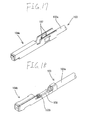
104a and a crimp terminal 104b. As shown in Fig. 17, the
insulation displacement terminal 104a is constituted by means
of press-fitting the electric wire 103 into pressure-connecting
blades 107. As shown in Fig. 18, an insulating sheath 103a
provided at the extremity of the electric wire 103 is stripped,
thereby uncovering cores 103b. The thus-exposed cores 103b are
crimped by means of a wire barrel 108, thereby constituting the
insulation displacement terminal 104b.
In connection with the crimp terminal 104b, the cores 103b
are strongly crimped by the wire barrel 108 by means of a press.
Hence, there is yielded an advantage of superior reliability
of electrical contact with the electric wire 103. Further, the
crimp terminal 104b possesses high tensile strength and is less
impervious to causing removal of the electric wire 103. However,
processing pertaining to complicated processes, such as
stripping of the electric wire 103 and crimping of the electric
wire using a press machine, must be performed for each of the
crimp terminals 104b (for each electric wire 103). Thus, the
wiring harness becomes costly, thereby deteriorating
manufacturing efficiency.
In connection with the insulation displacement terminal
104a, there is no necessity of stripping the electric wire 10
or press-fitting the electric wire 103 to the insulation
displacement terminal 104a. The only requirement is to merely
push the electric wire 103 into the pressure-connecting blades
107. By means of a single operation, a plurality of electric
wires 103 can be pressure-connected to a plurality of insulation
displacement terminals 104a aligned in line. Further, a
process of inserting the insulation displacement terminal 104a
crimped to the electric wire 103 into the connectors 102A
through 102E can be automated. Hence, there is yielded an
advantage of ability to efficiently manufacture sub-harnesses
at lower cost.
In order to curtail manufacturing costs or improve
manufacturing efficiency, all terminal hardware pieces,
including the terminals 104F to be inserted into the connectors
102A through 102E and after-insertion terminals 104R which
remain exposed and are not inserted into the connectors 102A
through 102E when the sub-harnesses 101X and 101Y are not
combined, are desirably formed from the insulation displacement
terminals 104a.
However, in relation to the insulation displacement
terminal 104a, the electric wire 103 is merely press-fitted into
the pressure-connecting blades 107. Hence, the electric wire
103 is readily removed from the insulation displacement
terminal 104a. Further, press-fitting is inferior to crimping
in terms of protection of a connection section (i.e., a
pressure-connecting section) under external force. The
after-insertion terminals 104R are transported or handled while
temporarily being in an exposed state. Against such a backdrop,
crimp terminals 104b, rather than insulation displacement
terminals 104a, are more preferably employed as the
after-insertion terminals 104R.
In relation to the electric wire 103 of the
after-insertion terminal 104R, there is a conceivable method
of connecting the insulation displacement terminals 104a to
ends of the electric wires 103 to be inserted into the connectors
102A through 102E and connecting the crimp terminals 104b to
the remaining ends of the electric wires 103 as the
after-insertion terminals 104R. However, connecting two
different connection types of terminal hardware pieces; that
is, the insulation displacement terminal 104a involving
press-fitting and the crimp terminal 104b involving crimping,
to a single electric wire 103 results in considerable
deterioration of manufacturing efficiency. Hence, such a
method is desirably avoided.
Crimping is not applied solely to connection of the
after-insertion terminal 104R. For instance, terminal
hardware (see Fig. 19) to be connected to an electric wire of
special form, such as a shield wire 103S having a shield layer
103Sa, and terminal hardware (see Fig. 20) which is to be used
in an exposed form and not connected to a connector even when
a wiring harness is completed (see Fig. 20), such as a ground
terminal 104E, must employ crimping as a connecting method.
As mentioned above, in terms of cost, use of the insulation
displacement terminals 104a is preferable at the time of
manufacture of the sub-harnesses 101X and 101Y and a wiring
harness. In spite of this, there has been a necessity of
employing crimp terminals 104b for a portion of terminal
hardware pieces. Further, difficulty is encountered in
mixedly employing the crimp terminal 104b and the insulation
displacement terminal 104a for each of the sub-harnesses 101X
and 101Y. Hence, the majority of related- art sub-harnesses
101X and 101Y use only the crimp terminals 104b. The insulation
displacement terminals 104a are used in only special portions
of a sub-harness where there is no necessity of using the crimp
terminals 104b.
SUMMARY OF THE INVENTION
The present invention has been conceived against the
foregoing backdrop and an object of the invention is to provide
a wiring harness which enables effective heavy use of
sub-harnesses using insulation displacement terminals.
To this end, the present invention provides a wire harness
formed by combination of a plurality of sub-harnesses,
comprising:
The present invention also provides a wire harness formed
by combination of a plurality of sub-harnesses, comprising:
Preferably, the second sub-harness has a shield line
having crimp terminals provided at both ends, the crimp
terminals being inserted into the housing, and/or an earth line
having at one end a crimp terminal inserted into the housing
and at the other end an uninserted earth terminal.
Preferably, the sharable housing has a retainer mount hole
communicating to an exterior surface of the sharable housing
from an inner wall of the cavity into which the crimp terminal
or the insulation displacement terminal is inserted, and a
retainer for preventing removal of the crimp terminal and/or
the insulation displacement terminal attached to the retainer
mount hole.
Preferably, a connection section is formed in each of the
crimp terminal and the insulation displacement terminal so as
to become identical in shape with a mating terminal; a step is
formed in the crimp terminal so as to become identical in shape
with the insulation displacement terminal; and a terminal
engagement section is formed in the retainer for preventing
removal of the crimp terminal and/or the insulation
displacement terminal by means of engaging with the step.
There is employed, as a housing for interconnecting the
first and second sub-harnesses, a sharable housing compatible
with a crimp terminal and a insulation displacement terminal.
Only terminal hardware to be connected to an after-insertion
electric require which requires adhesion strength between an
electric wire and terminal hardware is embodied as a crimp
terminal. The majority of terminal hardware pieces which do
not require adhesion strength are embodied as insulation
displacement terminals. Thus, the present invention is
advantageous in terms of cost and manufacturing efficiency.
The first insulation displacement sub-harness is
provided with a sharable housing compatible with a crimp
terminal and a insulation displacement terminal. A crimp
terminal of the after-insertion electric wire of the second
crimp sub-harness is inserted into the sharable housing. Thus,
the insulation displacement sub-harness and the crimp
sub-harness can be coupled together. Of the two sub-harnesses
coupled together, a insulation displacement terminal is used
for the first sub-harness. When compared with a case where all
terminal hardware pieces are embodied as crimp terminals, the
present invention is advantageous in terms of cost and
manufacturing efficiency.
When either a crimp terminal or a insulation displacement
terminal is embodied as terminal to be inserted into a cavity,
the terminal hardware can be locked without fail.
The crimp terminal or the insulation displacement
terminal inserted into the cavity is locked by means of engaging
the step of the crimp terminal or insulation displacement
terminal with the terminal engagement section.
BRIEF DESCRIPTION OF THE DRAWINGS
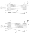
Figs. 1A and 1B are block diagrams showing a process of
coupling sub-harnesses according to a first embodiment of the
present invention.
Fig. 2 is a cross-sectional view showing crimp terminals
and insulation displacement terminals when they are inserted
into a sharable housing.
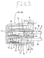
Fig. 3 is a cross-sectional view showing the crimp
terminals and the insulation displacement terminals when they
are inserted into and subjected to primary engagement.
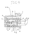
Fig. 4 is a cross-sectional view showing the inserted
crimp terminals and the insulation displacement terminals when
they are double engaged.
Fig. 5 is a perspective view showing a crimp terminal.
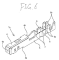
Fig. 6 is a perspective view showing a insulation
displacement terminal.
Fig. 7 is a perspective overview of a pressure-connecting
apparatus.
Fig. 8 is an enlarged perspective fragmentary view of the
pressure-connecting apparatus.
Figs. 9A and 9B are schematic diagrams showing a
sub-harness coupling process according to a second embodiment
of the present invention.
Figs. 10A and 10B are schematic diagrams showing a
sub-harness coupling process according to a third embodiment
of the present invention.
Figs. 11A and 11B are schematic diagrams showing a
sub-harness coupling process according to a fourth embodiment
of the present invention.
Figs. 12A and 12B are schematic diagrams showing a
sub-harness coupling process according to a fifth embodiment
of the present invention.
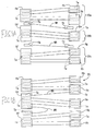
Figs. 13A and 13B are schematic diagrams showing a
modification of the insulation displacement sub-harness
according to a sixth embodiment of the present invention.
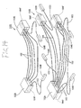
Fig. 14 is a perspective view showing related-art
sub-harnesses before they are coupled together.
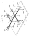
Fig. 15 is a perspective view showing a process of coupling
related-art sub-harnesses.
Fig. 16 is a perspective view showing a process of coupling
related-art sub-harnesses.
Fig. 17 is a perspective view showing a related-art
insulation displacement terminal.
Fig. 18 is a perspective view showing a related-art crimp
terminal.
Fig. 19 is a perspective view showing a connection between
a related-art shield wire and a crimp terminal.
Fig. 20 is a perspective view showing related-art
connection terminal hardware between an earth terminal and an
electric wire.
DETAIELD DESCRIPTION OF THE PRESENT INVENTION
First Embodiment
A first embodiment embodying the present invention will
be described hereinbelow by reference to Figs. 1A through 8.
A wiring harness 10 according to a first embodiment of
the present invention is formed by means of coupling two
sub-harnesses 10a and 10b of pressure-connecting type through
use of two after-insertion electric wires WR. Each of the
sub-harnesses 10a and 10b is formed from a plurality of sharable
housings Ha through Hg, a plurality of electric wires W, and
a plurality of insulation displacement terminals Ta.
The sharable housings Ha through Hg are designed so as
to enable insertion of terminal hardware pieces, such as crimp
terminals Tb and insulation displacement terminals Ta. The
sharable housings Ha through Hg are formed from synthetic resin
into a substantially-parallelepiped shape. Cavities 1 are
formed in two-layer rows within the sharable housings Ha through
Hg, so as to become open in the longitudinal direction. Crimp
terminals Tb or insulation displacement terminals Ta are
inserted into the cavities 1 from the rear. A lance 1a which
can deflect in the vertical direction is formed on an upper wall
surface at a front section of the inside of the cavity 1 so as
to assume a cantilever shape extending in the forward direction.
The lance 1a is engaged with a lance engagement hole 4b of the
crimp terminal Tb and with a lance engagement hole 4b of the
insulation displacement terminal Ta, thereby temporarily
holding the crimp terminal Tb and the insulation displacement
terminal Ta within the cavities 1. Retainer mount holes 2
communicating with the lower surface of the sharable housings
Ha through Hg from the cavities 1 are formed in the sharable
housings Ha through Hg. Retainers 3 to be described later are
assembled into the retainer mount holes 2.
The retainers 3 are formed from synthetic resin and are
inserted into the retainer mount holes 2. As a result, the
retainers 3 are assembled into the sharable housings Ha through
Hg. The retainers 3 can be engaged at a temporary engagement
position (see Figs. 2 and 3) and an engagement position (see
Fig. 4) located deeper than the temporary engagement position
within the retainer mount hole 2. Terminal engagement sections
3a which can be engaged with both the crimp terminal Tb and the
insulation displacement terminal Ta are provided in the
retainers 3 in the form of two-layer rows so as to match the
cavities 1. When the retainer 3 is located in a temporary
engagement position, the terminal engagement section 3a is
flush with the interior wall surface of the cavity 1. Therefore,
insertion and removal of the crimp terminal Tb or the insulation
displacement terminal Ta into and from the cavities 1 are
allowed. When the retainers 3 are pushed from the temporary
engagement position to the engagement position, the terminal
engagement section 3a proceeds into the cavity 1, to thereby
engage with a step of the crimp terminal Tb or a step of the
insulation displacement terminal Ta in a normally-inserted
state from the rear. The crimp terminal Tb or the insulation
displacement terminal Ta that has been inserted is further
locked unremovably.
The crimp terminal Tb is to be connected to a core wire
Wb which is exposed by means of stripping an insulating sheath
Wa at the extremity of the electric wire W. The crimp terminal
Tb is formed by means of punching a conductive metal plate into
a predetermined shape and bending the thus-punched plate. An
angularly cylindrical connection section 4 capable of receiving
a tab of male terminal hardware of a mating retainer (not shown)
and a resilient contact piece 4a which is provided in the
connection section 4 and comes into resilient contact with the
tab are formed in a front section of the crimp terminal Tb. A
lance engagement hole 4b capable of engaging with the lance 1a
in each of the sharable housings Ha through Hg is formed in the
connection section 4. A rear edge of the connection section
4 constitutes a step 4c, and the terminal engagement section
3a of the retainer 3 is engaged with the step 4c.
A wire barrel 6a and an insulation barrel 6b are formed
in the rear of the step 4c so as to be continuous. The wire
barrel 6a is shared between the connection section 4 and a bottom
wall 5 and is lower than the connection section 4 (shown upside
down in Figs. 2 through 4). The wire barrel 6a is crimped to
the exposed core wire Wb of the electric wire W, thereby
electrically connecting the crimp terminal Tb with the electric
wire W. The insulation barrel 6b is crimped to the insulation
sheath Wa.
Pressure-connecting sections 7 which are to be connected
to the internal core wire WB are formed in the insulation
displacement terminal Ta, by means of forming notches in the
insulating sheath Wa of the electric wire W. The insulation
displacement terminal Ta is formed by means of bending a
conductive metal plate punched into a predetermined geometry.
The angularly cylindrical connection section 4 capable of
receiving a tab of male terminal hardware and the resilient
contact piece 4a which is provided in the connection section
4 and comes into resilient contact with the tab are formed in
a front section of the insulation displacement terminal Ta. The
lance engagement hole 4b capable of engaging with the lance 1a
in each of the sharable housings Ha through Hg is formed in the
connection section 4. The connection section 4, the resilient
contact piece 4a, and the lance engagement hole 4b of the
insulation displacement terminal Ta are formed so as to become
identical in shape and size with the connection section 4, the
resilient contact piece 4a, and the lance engagement hole 4b
of the crimp terminal Tb. Further, the rear edge of the
connection section 4 constitutes the step 4c. The terminal
engagement section 3a of the retainer 3 is engaged with the step
4c. More specifically, the step 4c of the insulation
displacement terminal Ta is formed identical in shape and size
with the step 4c of the crimp terminal Tb.
Pressure-connecting sections 7 are formed in the rear of
the connection section 4. The pressure-connecting sections 7
are shared between the connection section 4 and the bottom wall
5 and are lower than the connection section 4 (shown upside down
in Figs. 2 through 4). The pressure-connecting sections 7 are
formed, by means of bending side walls 8 which stand upright
from the bottom wall 5 inwardly so as to assume a V-shaped cross
section. The electric wire W is pushed into the space between
the sidewalls 8 while the insulating sheath Wa remains
unstripped. As a result of the electric wire W being pushed
into the space between the sidewalls 8, the V-shaped press
section 7 cuts the insulating sheath Wa and comes into contact
with the core wire Wb. Thus, the insulation displacement
terminal Ta is electrically connected to the electric wire W.
The step 4c identical with the crimp terminal Tb is formed along
the rear edge of the connection section 4b. Hence, the
pressure-connecting section 7 is lower than the connection
section 4. However, the pressure-connecting section 4 is
formed into the shape of a letter V. Hence, a broad contact
area between the pressure-connecting section 7 and the core wire
Wb can be ensured. Consequently, there can be prevented a drop
in contact reliability, which would otherwise be caused by
reducing the height of the pressure-connecting section 7. In
other words, a contact area is ensured by means of forming the
pressure-connecting section 7 into the shape of a letter V,
thereby forming the step 4c while the pressure-connecting
sections 7 are made lower.
A pair of tabs 9a are projectingly formed at the rear edge
of the pressure-connecting sections 7. The tabs 9a protrude
so as to match in height with the connection section 4. When
the insulation displacement contact Ta is inserted into the
cavity 1, the upper edge of each of the tabs 9a comes into contact
with the internal wall of the cavity 1, thereby regulating
vertical movement of the rear edge of the insulation
displacement terminal Ta. A pair of caulking sections 9b are
projectingly formed in the rear portions of the tabs 9a. When
the caulking sections 9b are caulked by the insulating sheath
Wa of the electric wire W, the electric wire W is fixed.
After the electric wire W has been pressure-connected to
the insulation displacement terminal Ta outside the sharable
housings Ha through Hg, the insulation displacement terminal
Ta is inserted into the sharable housings Ha through Hb.
Automatic insertion machines for this purpose will now be
described by reference to Figs. 7 and 8. Rails 52 are laid on
a table 51 in the longitudinal direction thereof and in a
position closer to the viewer with reference to the lateral
direction of the upper surface of the table 51. Pallets 54 which
slide over the rails 52 are provided on the rails 52.
Pressure-connecting retainers 55 are provided on each of the
pallets 54, and pressure-connecting operation is performed on
the pallets 54. A pressure-connecting press machine 56 for
effecting pressure-connecting operation is provided on the
center in the longitudinal direction of the upper surface of
the table 51. Further, there are provided a console panel 53
for operating the pressure-connecting press machine 56 and a
drive mechanism of each of the pallets 54. As shown in Fig.
8, a servo motor 58 is provided on top of a support member 57,
and the servo motor 58 supports a screw shaft 59a of a joint
lever 59 in a vertically-movable manner by means of a ball screw
structure. An upper hook 61a of an up-and-down lever 61 of a
pressure-connecting jig 60 is fitted to a hook-shaped lower end
of the joint lever 59. In association with vertical movement
of the joint lever 59 and the screw shaft 59a, the up-and-down
lever 61 and the pressure-connecting jig 60 are also moved
vertically.
Four up-and-low levers 61 of the pressure-connecting jig
60 are provided along the periphery of a disk 62 integrated with
the support member 57. Upper-end hooks 61a of the up-and-low
levers 61 are fitted to the periphery of the disk 52 and are
supported by the disk 52 in a slidable manner. The number of
pressure-connecting blades 13 is arbitrary. A guide 63 is
provided on either side of each of the up-and-low levers 61,
and the up-and-low lever 61 vertically travels along a space
between guides 63. Each of the guides 63 is rotated by a rotary
actuator 64 provided on top of the disk 62. An arbitrary
pressure-connecting jig 60 is set to a pressure-connecting
position. At this time, the lower-end hook of the joint lever
59 fills in a notch formed in the disk situated at the
pressure-connecting position. Hence, movement of the
up-and-low lever 61 cause no harm. A pulse motor may be employed
in place of the rotary actuator 64.
The pallets 54 are moved in the same manner as are the
up-and-low lever 61 of the pressure-connecting press machine
56. More specifically, a screw shaft of a ball screw on which
the pallets 54 are fastened is actuated by means of a servo motor.
The ball screw and the servo motor are situated below the pallets
54. Hence, although unillustrated, the ball screw and the servo
motor are actuated on the same principle on which the up-and-low
lever 61 of the pressure-connecting press machine 56 is actuated.
Here, details illustrations and explanations thereof are
omitted.
When the electric wire W is pressure-connected to the
insulation displacement contact Ta, the pallets 54 are placed
in a standby condition at predetermined positions. The
insulation displacement contact Ta is housed in each of hold
grooves 55a of each of the pressure-connecting retainers 55,
and the electric wire W is supplied to each of the crimp terminals
Ta. In this state, the pressure-connecting press machine 56
is actuated, thereby lowering the pressure-connecting jig 60.
The pressure-connecting jig 60 presses the electric wire W into
the pressure-connecting section 7 of the insulation
displacement contact Ta, thereby pressure-connecting the
electric wire w to the insulation displacement contact Ta.
After pressure-connecting operation, the pressure-connecting
jig 60 is elevated and held in a standby condition.
Subsequently, the pallets 54 are moved over the distance
equal to a pitch at which the insulation displacement terminals
Ta are held in the hold grooves 55a. Subsequently, the
pressure-connecting jig 60 is lowered, thereby
pressure-connecting the electric wire W to the solder-less
terminal Ta. After pressure-connecting operation, the
pressure-connecting jig 60 is elevated. The foregoing
processes are sequentially iterated, so that all the insulation
displacement terminals Ta held by the pressure-connecting
retainers 55 are pressure-connected to the electric wire W.
After having undergoing pressure-connecting operation,
the pressure-connecting retainer 55 is removed from the pallet
54 and transferred to an insertion apparatus (not shown) for
inserting the insulation displacement terminals Ta into the
sharable housings Ha to Hg. In the insertion apparatus, the
pressure-connecting retainers 55 are positioned relative to the
sharable housings Ha to Hg so as to fit into corresponding
cavities 1 from the rear. In this state, an insertion jig (not
shown) presses the tabs 9a of the insulation displacement
terminals Ta, so that the insulation displacement terminals Ta
are inserted into the sharable housings Ha to Hg.
With regard to insertion of the insulation displacement
terminals Ta, the insulation displacement terminals Ta may be
sequentially inserted into the shareable housings Ha to Hg one
by one. Alternatively, all the insulation displacement
terminals Ta may be inserted into the shareable cavities 1
simultaneously. In order to prevent removal of the electric
wires W from the insulation displacement terminals Ta after
pressure-connecting operation, attention is preferably paid to
avoid imparting tensile force to the electric wires W. Further,
processing preferably proceeds immediately to a process of
inserting the insulation displacement terminals into the
sharable housings Ha to Hg.
In the present embodiment, the electric wires W are
pressure-connected to the insulation displacement terminal Ta
of the pressure-connecting retainer 55 one by one.
Alternatively, a plurality of pressure-connecting jigs 60 may
be provided at the same pitch as that at which the insulation
displacement terminals Ta are provided in the hold grooves 55a,
and a plurality of electric wires W may be pressure-connected
to the insulation displacement terminals Ta simultaneously.
Next will be described processes of assembling
sub-harnesses 10a and 10b and manufacturing the wiring harness
10 by means of linking the sub-harnesses 10a and 10b. As shown
in Fig. 1A, the first sub-harness 10a is constituted of a
plurality of electric wires WF (identical in configuration with
the electric wires W), a plurality of insulation displacement
terminals Ta pressure-connected to either end of each of the
electric wires WF, and the sharable housings Ha through Hd. The
insulation displacement terminals Ta are pressure-connected to
the ends of the electric wires WF, and the insulation
displacement terminals Ta are inserted into the sharable
housings Ha through Hd in the same manner as mentioned above.
At the time of insertion of the insulation displacement
terminals Ta, the retainers 3 are held in the temporary
engagement position. The insulation displacement terminals Ta
that have been inserted into the regular position in this state
are doubly engaged and locked by means of two engagement
actions; namely, a first engagement action realized as a result
of the lances 1a engaging the lance engagement holes 4b, and
a second engagement action realized as a result of the terminal
engagement section 3a of the retainer 3 moving to the engagement
position after the first engagement action and being engaged
with the steps 4c. The cavity 1 is formed in each of two sharable
housings Hc and Hd so as to enable insertion of the crimp terminal
Tb of the after-insertion wire WR.
The second sub-harness 10b is assembled in the same manner
as the first sub-harness 10a. Some second sub-harnesses 10b
may differ from the first sub-harness 10a in terms of the number
of the sharable housings He through Hg and the number of electric
wires WF and the insulation displacement terminals Ta. Even
in the case of the second sub-harness 10b, the cavity 1 is formed
in each of two sharable housings He and Hg so as to enable
insertion of the crimp terminal Tb of the after-insertion wire
WR.
The two sub-harnesses 10a and 10b are connected together
by means of the two after-insertion electric wires WR. The
crimp terminal Tb is crimped to each end of each of the
after-insertion wires WR. The crimp terminal Tb crimped to one
end of such an after-insertion wire WR is inserted into a vacant
one of the cavities 1 formed in the sharable housings Hc and
Hd of the first sub-harness 10a. The crimp terminal Tb crimped
to the other end of the wire WR is inserted into one of the
cavities 1 formed in the sharable housings He and Hg. At the
time of insertion of the crimp terminal Tb into the cavity, the
retainer 3 is situated at the temporary engagement position,
as in the case of insertion of the insulation displacement
terminal Ta into the housing. The crimp terminals Tb that have
been inserted into the normal position in this state are doubly
engaged and locked by means of two engagement actions; namely,
a first engagement action realized as a result of the lances
1a engaging the lance engagement holes 4b, and a second
engagement action realized as a result of the terminal
engagement section 3a of the retainer 3 moving to the engagement
position after the first engagement action and being engaged
with the steps 4c. The cavity 1 is formed in each of two sharable
housings Hc and Hd so as to enable insertion of the crimp terminal
Tb of the after-insertion wire WR. Thus, the two sub-harnesses
10a and 10b are connected together by means of the
after-insertion electric wires WR, thereby completing the
wiring harness 10.
In relation to the sharable housings Hc, Hd, He, and Hg
having the insulation displacement terminals Ta and the crimp
terminals Tb inserted therein, the lance engagement holes 4b
to be used for first engagement action and the steps 4c to be
used for second engagement action are formed to the same shape
and size. Hence, the terminal hardware pieces Ta and Tb are
doubly engaged in the sharable housings Hc, Hd, He, and Hg
without fail. Since the connection sections 4 and the resilient
contact pieces 4a are formed to be equal in size and shape, the
terminal hardware pieces Ta and Tb are connected to the tab of
the male terminal hardware without involvement of a problem.
As mentioned above, in the present embodiment, there are
used the sharable housings Ha through Hg compatible with the
crimp terminals Tb and the insulation displacement terminals
Ta as the housings for connecting together the first and second
sub-harnesses 10a and 10b. Only the terminal hardware to be
connected to the after-insertion electric wires WR which
requires high adhesion strength between the electric wires W
and the terminal hardware is embodied as the crimp terminals
Tb. Further, the crimp terminals Tb are inserted into the
sharable housings Ha through Hg. Further, the insulation
displacement terminals Ta are used for the majority of terminal
hardware pieces, which do not require high adhesion strength.
Hence, the present invention is advantageous in terms of cost
and manufacturing efficiency.
Second Embodiment
A second embodiment embodying the present invention will
be described hereinbelow by reference to Fig. 9.
The second embodiment relates to a wire harness 20
constituted of three sub-harnesses 20a, 20b, and 20c of
pressure-connecting type and two after-insertion electric
wires WR. In other respects, the present embodiment is
identical in construction with the first embodiment. Those
constituent elements which are the same as those described in
connection with the first embodiment are assigned the same
reference numerals. The structure, operation, and
working-effect of the wire harness according to the present
embodiment are omitted.
The sub-harnesses 20a, 20b, and 20c are assembled in the
same manner as do the sub-harnesses 10a and 10b according to
the first embodiment. In connection with the first sub-harness
20a, one unoccupied cavity 1 is formed in the sharable housing
Ha for enabling insertion of the crimp terminal Tb of the
after-insertion electric wire. Further, in connection with
the third sub-harness 20c, one unoccupied cavity 1 is formed
in the sharable housing Hf for enabling insertion of the crimp
terminal Tb of the after-insertion electric wire. In the second
sub-harness 20b, two cavities 1 are formed in the single
sharable housing Hd for enabling insertion of the crimp terminal
Tb of the inserted after-insertion electric wire WR. In
relation to one of the after-insertion electric wires WR, the
crimp terminal Tb provided at one end of the electric wire WR
is inserted into the unoccupied cavity 1 of the sharable housing
Hc of the first sub-harness 20a. The crimp terminal Tb at the
other end is inserted into one of two unoccupied cavities 1 of
the sharable housing Hd of the second sub-harness 20a. Moreover,
in connection with the remaining after-insertion electric wire
WR, the crimp terminal Tb at one end is inserted into an
unoccupied cavity 1 of the sharable housing Hf of the third
sub-harness 20c. Moreover, the crimp terminal Tb at the other
end is inserted into the remaining one of the two unoccupied
cavities 1 of the sharable housing Hd of the second sub-harness
20b. Through the foregoing operations, the wire harness 20 is
completed.
Third Embodiment
A third embodiment embodying the present invention will
be described hereinbelow by reference to Fig. 10.
In the first and second embodiments, a wire harness
is constituted by means of interconnecting sub-harnesses. In
the third embodiment, however, a wire harness 30 is constituted
by means of connecting together a first insulation displacement
sub-harness 30a and a second crimp sub-harness 30b. In other
respects, the present embodiment is identical in construction
with the first embodiment. Those constituent elements which
are the same as those described in connection with the first
embodiment are assigned the same reference numerals. The
structure, operation, and working-effect of the wire harness
according to the present embodiment are omitted.
The first insulation displacement sub-harness 30a is
assembled in the same manner as do the sub-harnesses 10a and
10b described in connection with the first embodiment. An
unoccupied cavity 1 is formed in each of the sharable housings
Ha and Hc of the sub-harness 30a for enabling insertion of the
crimp terminal Tb of the after-insertion electric wire WR.
The second crimp sub-harness 30b employs a plurality of
sharable housings Hd to Hg which are identical in construction
with those employed in the first sub-harness 30a. The crimp
terminals Tb crimped to the ends of the electric wires WF are
inserted into the respective sharable housings Hd to Hg. As
in the case of the first embodiment, the thus-inserted crimp
terminal Tb is doubly engaged by the lance 1a and the retainer
3. Of the plurality of electric wires W, two electric wires
are taken as after-insertion electric wires WR. As shown in
Fig. 10A, the crimp terminals Tb crimped to one-side ends of
the after-insertion electric wires WR are inserted into the
sharable housings He and Hg. The crimp terminal Tb crimped to
the-other-side ends of the sharable housings He and Hg remain
uninserted and exposed outside. All the crimp terminals Tb
crimped to the respective ends of each of the electric wires
WF other than the after-insertion electric wires WR are inserted
into the sharable housings Hd to Hg.
At the time of assembly, the uninserted crimp terminals
Tb provided at the-other-side ends of the respective
after-insertion electric wires WR are inserted into the
unoccupied cavity 1 of the predetermined sharable housings Ha
and Hc of the first insulation displacement sub-harness 30a.
As shown in Fig. 10B, the first insulation displacement
sub-harness 30a and the second crimp sub-harness 30b are
connected together by way of the after-insertion electric wire
WR, thus completing the wire harness 30.
Fourth Embodiment
A fourth embodiment embodying the present invention will
be described hereinbelow by reference to Figs. 11A and 11B.
A wire harness 40 according to the fourth embodiment is
constituted by means of connecting together a first insulation
displacement sub-harness 40a and a second crimp sub-harness 40b,
as in the case of the third embodiment. However, the second
sub-harness 40b differs in construction from the second
sub-harness 30b employed in the third embodiment. More
specifically, of four electric wires constituting the second
sub-harness 40b, one electric wire is an after-insertion
electric wire WR; one is an earth wire WE; and the remaining
two wires are shield wires WS. A crimp terminal Tb is crimped
to either end of the after-insertion electric wire WR. The
crimp terminal Tb provided at one end is inserted into the
sharable housing He, and the crimp terminal Tb provided at the
other end remains uninserted and exposed. A crimp terminal Ta
is provided at one end of the earth electric wire WE by means
of crimping. An earth terminal Te is connected to the other
end of the earth electric wire WE by means of crimping. A
crimped structure formed between the earth terminal Te and the
earth electric wire WE is identical with that formed between
the after-insertion electric wire WR and the crimp terminal Tb.
Hence, explanation of the crimped structure is omitted here.
The crimp terminal Tb is crimped to either end of the shield
wire WS. The crimp terminals Tb are inserted into the sharable
housings Hd and He. At the time of assembly, the crimp terminal
Tb provided at the other end of the after-insertion electric
wire WR is inserted into the unoccupied cavity 1 of the sharable
housing Hb of the first sub-harness 40a. The earth terminal
Te is not inserted into any of the housings Ha through He and
is fixed to a predetermined earth position (not shown).
Fifth Embodiment
A fifth embodiment embodying the present invention will
now be described hereinbelow by reference to Figs. 12A and 12B.
A wire harness 50 according to a fifth embodiment is constituted
by means of connecting together a first insulation displacement
sub-harness 50a and a second insulation displacement
sub-harness 50b through use of coupling means having a crimp
terminal. A plurality of after-insertion electric wires WR
serving as coupling means are bundled. One-side ends of the
electric wires WR are connected together in a conductive manner
by means of a splice ting tool S. The other-side ends of the
electric wires WR are individually connected to crimp terminals
Tb. Of the plurality of after-insertion electric wires WR, the
other end of one after-insertion electric wire WR is inserted
into an unoccupied cavity 1 of the sharable housing Hb of the
first sub-harness 50a. The crimp terminal Tb provided at the
other end of another after-insertion electric wire WR is
inserted into an unoccupied cavity 1 of the sharable housing
Hd of the second sub-harness 50b, thereby constituting the wire
harness 50.
Sixth Embodiment
A sixth embodiment embodying the present invention will
now be described hereinbelow by reference to Figs. 12A and 12B.
The sixth embodiment shows a modification of the
insulation displacement sub-harness. In the previous
embodiments, all insulation displacement terminals Ta are used
as terminal hardware constituting the insulation displacement
sub-harness. In a sub-harness 60a according to the present
embodiment, a crimp terminal Tb crimped to one end of the earth
wire WE is inserted into one cavity 1 of one sharable housing
Hb. Further, the earth terminal Te is connected to the other
end of the earth wire WE by means of crimping. The earth
terminal Te is not inserted into any one of the sharable housings
Ha to Hc and is connected to grounded at a predetermined earth
position (not shown).
In each of the embodiments, a wire harness is assembled
by means of combining sub-harnesses together on a assembly work
bench such as that shown in Figs. 15 and 16.
Another Embodiment
The present invention is not limited to the embodiments
that have been described by reference to the foregoing
descriptions and drawings. The following embodiment also
falls within the scope invention, and the present invention can
be carried out in a modified manner within the scope of the
invention.