TECHNICAL FIELD
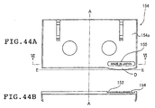
-
The present invention relates to a magnetic tape
cassette, its parts, a method of molding the parts, a
method of stamping a molded article and a molded article
fabricated by the method, particularly to a magnetic tape
cassette in which an opening portion into which a tape
loading device in a recording and reproducing apparatus can
be inserted is provided in a bottom surface of a casing and
furthermore in which a slider for opening and closing this
opening portion or a slider provided with a dust-proof wall
is arranged, and more specifically to improvement of the
structure of the above-described slider. Further, the
present invention Further relates to a method of molding a
slider to be mounted on the outside of a lower half for
protecting a magnetic tape accommodated within a magnetic
tape cassette; a magnetic tape cassette with an improved
brake member for limiting rotation of a take-up hub for
preventing a loosening of a magnetic tape accommodated
within the magnetic tape cassette; and a plate spring used
in a magnetic tape cassette or the like, more specifically
to a plate spring having an extremely large deformation
amount like a slider spring of a magnetic tape cassette.
Further, the present invention relates to a stamping method
of a plastic molded article such as a magnetic tape
cassette or the like whose surface is stamped and a molded
article such as a magnetic tape cassette or the like, more
specifically to a stamping method of a molded article whose
surface is stamped without degrading dimensional precision
by molding with molds provided with stamping surfaces; and
to a plastic molded article such as a magnetic tape
cassette or the like in which a stamped portion is provided
in its surface, a dimensional balance is excellent, and
there is no rattle or peeling of resin during assembling
or using it.
BACKGROUND ART
-
A magnetic tape cassette that can record digital
signFurthern a magnetic tape at a high density is
conventionally known. For example, a DDS for recording
data of a computer or a DAT used for an audio system is
known as such a small and light magnetic tape cassette.
-
In such a magnetic tape cassette, hubs around which a
magnetic tape is wound are accommodated in right and left
portions of a casing, and the above-described opening
portion is provided in a front surface and a bottom surface
of the casing so that the tape cassette may be loaded to
the above-described magnetic tape by a tape loading device.
Further, in order to prevent dust or the like from entering
through the opening portion from the outside, a slider for
closing the above-described opening portion at the bottom
surface is disposed so as to be slidable in a loading
direction of the tape cassette along the bottom surface
side of the casing.
-
With respect to the above-described tape cassette, a
conventional arts for opening and closing the slider
installed slidably back and forth to the casing in response
to the loading operation of the tape cassette to the
recording and reproducing apparatus is disclosed in, for
example, JP 60-129985 A, JP 60-136078 A, JP 60-136879 A and
JP 60-175271 A.
-
Further, when the slider is to be mounted slidably
onto the bottom surface of the casing, when the slider is
brought into totally sliding contact with the bottom
surface of the casing, the sliding resistance becomes
excessive with even a slight error in manufacturing
precision, or with internal strain or thermal deformation,
thereby resulting in malfunction of the slider.
Accordingly, a piece of art for providing a rib-shaped
projection extending in a back-and-forth direction on the
inner surface of the slider and causing the slider to
slidably contact with the casing through this projection is
disclosed in, for example, JP 7-21952 B. In this
conventional art, a locking mechanism is provided for
locking the slider in an open position and a closed
position, and a concave guide groove for guiding a lock
release member for releasing the locked condition is formed
on the bottom surface of the slider.
-
Fig. 32 shows a structural example of a slider 104 of
a conventional tape cassette. The overall structure will
be described later. Through- holes 114 and 115 engaging tip
ends of elastic lock pieces of the casing are opened in
this slider 104, and convex guide grooves 116 for guiding
lock release member for releasing this engagement is
provided at the bottom surface. Furthermore, on the top
surface of the slider 104, projections 120 slidingly
contacting a bottom surface of a lower half 102 (see Fig.
33) is formed such that they extend in rib-shaped manner
over the entire length in the sliding direction from a
front end to a rear end of the slider 104. The structure
other than above-mentioned will be explained by using the
same reference numerals for the same components as those
shown in Fig. 33 to be described later. Therefore, for
description thereof, refer to the explanation later.
-
Note that, in the tape cassette having the slider
according to the above-described conventional art, the
projections are provided at the slider over the entire
longitudinal portion thereof in the sliding direction
including the concave grooves having a substantially
rectangular shape for guiding the lock release members, so
that a thick portion and a thin portion are arranged
adjacent by each other in the slider. Accordingly,
"warpage" is apt to occur in a form after the molding and
there might occur a fear that dimensional precision
degrades to cause various faults.
-
Namely, because a portion where the above-described
concave grooves for guiding the above-described lock
release members are formed becomes thin when molding the
slider, whereby fluidization of resin becomes non-smooth,
and Further a local strain occurs in a molded article.
Therefore, "warpage" or partial deformation would occur.
There are Further problems in terms of outer appearance.
Concretely, a transfer fault of patterns, weld lines, non-uniformity in appearance, shrinkage or the like is apt to
occur.
-
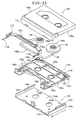
Further, in one example as shown in Fig. 33, the
magnetic tape cassette is basically constituted by an upper
half 100, a lower half 102 coupled with the above-described
upper half 100 to form a casing, a slider coupled thereto
so as to be slidable in a back-and-forth direction (the
direction indicated by an arrow A) of the casing along the
bottom surface and side surfaces of the lower half 102 and
a magnetic tape 34 accommodated in the casing.
-
In this magnetic tape cassette, the slider 104 has a
rectangular engagement sliding portions 104e, 104e by a
longitudinal side at a rear end inner edge of right and
left side walls 104a, 104a. As indicated by the dotted
lines in Fig. 34, when the upper half 100 and the lower
half 102 are coupled to form the casing, the engagement
sliding portions 104e, 104e are slidably attached and
inserted into sliding grooves 122 formed, respectively, in
a space between a left side wall 100a of the upper half 100
and a left side wall 102e of the lower half 102 and a space
between a right side wall 100a of the upper half 100 and a
right side wall 102e of the lower half 102. Each of the
lower surfaces of the engagement sliding portions 104e,
104e are slidably attached to and engaged with the top
surfaces of right and left side walls of the lower half 102,
respectively.
-
As shown in Fig. 34, when the magnetic tape is not
used, the slider 104 is engaged and retained by an
engagement lock mechanism arranged on the bottom surface
102a of the lower half 102 with its front end portion 124
in an advanced position in abutment with an inner end of a
front lid 112 of the upper half 100, thereby closing drive
shaft insertion holes 102b, 102b on the feed side and the
take-up side of the lower half 102. Thus it is possible to
prevent dust or foreign matters from entering from below of
the drive shaft insertion holes 102b, 102b.
-
Further, during use of the magnetic tape, the
engagement lock mechanism is released by the magnetic tap
recording and reproducing apparatus, while rear ends 104f,
104f of the right and left side walls 104d, 104d are
slidably retracted to an abutment position with inner side
wall ends 126a, 126a of the rear side wall 126 of the lower
half 102, respectively. At this time, guide holes 104b,
104b formed in the bottom surface 104a of the slider 104
coincide with the drive shaft insertion holes 102b, 102b of
the hubs on the feed side and the take-up side of the
above-described lower half 102 to open the above-described
drive shaft insertion holes 102b, 102b.
-
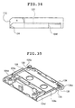
As shown in Figs. 34 and 35, in this magnetic tape
cassette, when the slider 104 is located in an advanced
position, opening portions 128, 128 are formed
corresponding to a retracted position of the advanced
slider 104 at lower portions on both sides of the casing
between the rear ends 104f, 104f of the right and left side
walls 104d, 104d of the slider 104 and the inside wall ends
126a, 126a of rear side wall 126 of lower half 102. These
opening portions 128, 128 may be utilized as portions that
are gripped by chucks of an automatic loader when the
magnetic tape cassette is automatically loaded in the
recording and reproducing apparatus by the automatic loader.
-
Conventionally, as shown in Fig. 35, closing walls
130, 130 extends upwardly from the bottom surface of the
lower half 102 in these opening portions 128, 128. As
shown in Fig. 35, these closing walls 130, 130 are
respectively overlapped with the rear ends 104f, 104f of
right and left side walls of the slider 104 to close an
inner deep portion of the opening portions 128, 128 to
serve to prevent invasion of dust or foreign matters.
-
In this magnetic tape cassette, portions where the
closing walls 130, 130 are provided correspond to outer
contours of regions into which the magnetic tape wound by
the feed side hub 106 or the take-up side hub 106 of the
magnetic tape are accommodated. Thus, the portions are
formed such that the closing walls 130, 130 are not in into
contact with the magnetic tape when the latter is wound
around either one of the feed side hub and the take-up hub
and the wound magnetic tape has a maximum diameter. In
order to secure an amount of the magnetic tape that can be
accommodated in the casing as much as possible, it is
necessary to broaden the winding space as much as possible,
and it is thus necessary to form the closing wall as thin
as possible.
-
In order to serve to prevent the invasion of dust or
foreign matters, it is necessary to make these closing
walls 130, 130 to have such a continuous height that the
closing walls may close at least the opening portions 128,
128. Further, if, in order to secure the winding space of
the magnetic tape as much as possible, thickness of the
closing walls is decreased, it may become difficult for
molten resin, which is introduced into the molds during
molding, to flow through a cavity corresponding to these
portions , thereby causing a problem in molding. If
thickness of the closing walls is sufficiently increased
in order to avoid this problem in molding, then it is
impossible to secure sufficient tape winding space, causing
a problem that a winding amount of magnetic tape cannot be
secured to a maximum.
-
Further, as described above, in a magnetic tape
cassette such as a DDS, a DAT or the like, both ends of an
elongated magnetic tape are fixed, and a pair of hubs or
take-up reels around which this magnetic tape is wound are
accommodated in a case that exposes only the magnetic tape
at a portion tensioned between these two take-up hubs or
take-up reels.
-
Fig. 36 shows an example of such a magnetic tape
cassette. A body of a magnetic tape cassette 140 is
composed of an upper half 141 and a lower half 142 coupled
in a lid-mating manner. Because a high density recording
is performed on the magnetic tape, in particular in order
to prevent a finger from touching a magnetic tape or dust
from attaching thereto, it is necessary to improve
sealability of the casing. Therefore, a front lid (lid)
141a for covering a front surface side from which the
above-described magnetic tape is exposed, is provided at
the upper half 141.A slider 143 for covering the lower
surface side of the cassette case is mounted on an outer
lower surface of the lower half 142.
-
As shown in Fig. 36, the slider 143 is provided with
side walls 143b, 143b extending vertically from a
rectangular bottom surface 143a (horizontal surface) on
both right and left ends of the bottom surface, havingg a
U-shape. Dust preventing wall portions 143c, 143c that are
thin elongated parallelepiped members are partially
provided at upper ends of the side walls 143b, 143b. These
portions are engaged with the side walls of the lower half
142 to prevent the slider 143 from dropping out from there
and to improve dust-proof effect, thereby facilitating
smooth sliding motion of the slider 143.
-
Generally, the slider is manufactured by injection
molding of thermoplastic resin such as POM, PS, ABS or the
like. Usually, this molding is performed by injecting
molten resin into a space formed by molding operation using
such as a movable side mold (core) and a stationary side
mold (cavity).
-
Fig. 37 is a plan view of the slider 143. Fig. 38
shows a state in which a portion of a cross-section taken
along the line VI-VI of side wall 143 of slider 143 is
molded by molding. As shown in Fig. 38, the slider 143 is
formed by injecting molten resin into a space between a
main core (movable side mold) 144 and a cavity (stationary
side metal mold).
-
However, after completion of molding, when the molds
are opened and the molded article is held on the core side
and is removed from the mold using a projecting pin, in a
case of a substantially U-shaped and plate-shaped molded
article such as the above-described slider, there is a
problem that warpage phenomenon in which the side walls are
tilted inwardly and the bottom surface portion is bulged
might be apt to occur, resulting in obtaining a defective
article.
-
Then, in order to prevent the side walls 143b from
being tilted, for example, countermeasure of providing
grooves 143d at proximal ends of the side walls 143b or the
like had been adapted. However, this could not overcome
the problem completely.
-
Further, with respect to the portions of the side
walls 143b having a shape as shown in Fig. 38, the main
core 144 may move upwardly to open the molds. However,
with respect to a portion of the cross-section taken along
the line VII-VII of Fig. 37, as in the state of molding
with molds as shown in Fig. 39, the mold cannot be movedd
upwardly because the dust-proof portion 143c is present at
the upper end of the side wall 143b. Accordingly, a slide
core 146 moving laterally is needed. Namely, as shown in
Fig. 39, mold for molding the L-shaped bent portion formed
by the side wall 143b and the dust-proof wall portion 143c
is formed by a slide core 146 and a side core 147 in
addition to a main core 144 and a cavity 145. The slide
core 146 moves in the lateral direction (in a direction
normal to the drawing plane). In the plan view of Fig. 37,
each portion corresponding to the slide core 146 is
represented by shaded portions 148. In Fig. 37, the slide
core 146 moved downwardly of the paper surface of the
drawing.
-
In Fig. 39, after molding, first of all, the slider
core 146 is removed laterally and the main core 144 and the
side core 147 are moved upwardly. Then, because the slide
core 146 has already been removed as shown in an enlarged
view of the side wall 143b and the side core 147 in Fig. 40,
the side wall 143b (and dust-proof wall portion 143c) is
held by the main core 144 as shown in Fig. 38 and therefore
the force for retaining the side wall 143b is made to be
decreased. As a result, in some cases, the side wall 143b
(end portion of the dust-proof wall portion 143c) may
happen to ride over the side core 147. The ride of the
side wall 143b over the side core 147 is not essentially
preferable as described below.
-
Then the state of the slider 143 as viewed in a
direction as indicated by the arrow of Fig. 37 is shown in
Fig. 41. Fig. 41 shows a state in which the right side
wall 143b rides over the side core 147 and is bent with
respect to only the side wall 143b on the right side. The
situation is the same Further for the left side wall. Fig.
42 shows a state of the condition of the side wall 143b at
this time as viewed from in a direction indicated by the
arrow B of Fig. 37. Because only the portion of the dust-proof
wall portion 143c rides over the side core 147, the
side wall 143b is deformed as indicated by the dotted lines
in Fig. 42.
-
Because the side wall 143b rises over the side core
147, the side wall 143b is rubbed by an edge of the side
core 147 to bring about damaging or curling. When damaging
or curling is generated in the side wall 143b of the slider,
this may cause malfunction. Especially, if curling is
generated at an edge of the dust-proof wall portion 143c,
this causes sliding defect of the slider 143 or assembling
defect of the cassette.
-
Furthermore, conventionally, when a letter such as a
name of a maker, a name of a product, a product type, and a
size, or figures such as logotype marks are displayed on a
plastic portion having a thin plate portion having a small
thickness of 1.5 mm or less, such as an upper half, a lower
half, a slider and a front lid constituting a magnetic tape
cassette, a concave pattern or a convex pattern is stamped
in advance onto the mold. The molding material is molded
using this mold to form a convex or a concave portion of
desired letters or figures on the molded article surface,
thereby forming a stamped portion.
-
However, when such a stamped portion is displayed on
a surface of the molded article, if the letters or figures
are concave, it is difficult to recognize the letters or
figures and it is impossible to sufficiently satisfy
function of display. On the other hand, if they are
displayed in a convex shape, when there is a member brought
into sliding contact with the molded article during
operator's using, there occurs a problem that the stamped
portion is hooked at that member or a problem that
thickness of the displayed portion is increased even in a
case of formation of a thin molded article, with the result
that thinning processing is quite rendered meaningless.
-
Then, in order to overcome the above-noted problems,
a method is taken in which a concave groove portion is once
provided at a surface of the molded article and the letters
or figures are molded in a convex manner within the groove
portion to form the stamped portion. The molded article
with the stamped portion through the conventional stamping
method will now be described with reference to Fig. 33 and
Figs. 43A to 44B. Fig. 33 is an exploded perspective view
illustrative of an example of main constituents of a
magnetic tape cassette as an example of a plastic molded
article to which a stamp is applied.
-
For example, in a magnetic tape cassette such as a
DAT, a DDS or the like known as a recording medium for
recording digital signals at a high density on a magnetic
tape, as shown in the above-described Fig. 33, a box member
is constituted in a lid mating manner and is mainly formed
by an upper half 100 and a lower half 102 for forming a
casing of a magnetic tape(cassette case), a slider 104
provided in contact with the bottom surface of the lower
half 102 from outside and mounted slidably back and forth
and a magnetic tape 108 wound around a take-up hub 106.
-
As shown in Fig. 33, in the magnetic tape cassette,
both end portions of the elongated strip-shaped magnetic
tape 108 are fixed to a pair of take-up hubs 106, 106, and
the magnetic tape 108 are wound around the respective take-up
hubs 106, 106 from its both end portions. The pair of
hubs 106, 106 on which the magnetic tape 108 are wound is
accommodated in the cassette case obtained by coupling the
upper half 100 and the lower half 102 in a lid-mating
manner so as to keep the pair of take-up hubs 106, 106,
around which the magnetic tape 108 is wound, rotatable.
The magnetic tape 108 between the pair of take-up hubs 106,
106 is suspended through a predetermined path, so that only
the projecting portion 108a of the magnetic tape
corresponding to a position of the magnetic head of the
recording and reproducing apparatus (not shown) will be
able to be exposed to the outside.
-
In order to prevent a finger from touching a magnetic
layer surface of the magnetic tape 108a of the projecting
portion capable of being exposed from this cassette case or
preventing dust from sticking thereto, a front lid 112
pivoted about pins is provided in the upper half 100 so as
to swing between the closing position for covering the
magnetic tape 108a of a projecting portion and an opening
position for exposing the tape.
-
A gear 106a formed integrally with a top end face of
the take-up hub 106 is provided at the take-up hub 106.
This gear 106a engages with a brake piece 110a of a brake
member 110 assembled in the upper half 100 to retain
rotation in a direction in which the magnetic tape 108 is
loosened and serves to prevent occurrence of loosening of
the magnetic tape 108 due to vibration, shock or the like
upon delivery or handling of the magnetic tape cassette
while it is not used. A pair of brake pieces 110a is
engaged with the gears 106a of the associated take-up hubs
106, respectively. The brake member 110 is spring-biased
backwardly toward the take-up hubs 106 by a brake spring
(not shown) composed of a torsion coil spring fitted around
a pin (not shown) provided on the upper half 100.
-
When the magnetic tape cassette is not being used,
the brake member 110 is located at a stop position for
stopping rotation of the take-up hub 106 while the braking
pieces 110a are engaged with the gears 106a by biasing
force of the brake spring (not shown). When the cassette
is loaded into the recording and reproducing apparatus, the
front surface lid 112 is rotated by the recording and
reproducing apparatus, the brake arms 110b provided to
extend forwardly from both right and left ends of the brake
member 110 and engage with the front surface lid 112, and
the brake pieces 110a are separated away from the gears
106a and moved to the release position where the take-up
hubs 106 can be rotated.
-
The lower half 102 has a bottom surface 102a of a
rectangular shape. The take-up hub 106 is rotatably
supported to the bottom surface 102a. When the magnetic
tape cassette is loaded into the recording and reproducing
apparatus, a reel shaft (not shown) is inserted into the
take-up hub 106 from the recording and reproducing
apparatus. The lower half has reel shaft insertion holes
102b, 102b for drivingly rotating the take-up hubs 106.
Both right and left ends of the bottom surface 102a are
projecting portions 102c, 102c extending forwardly. A
space between the projecting portions 102c, 102c is
directed to a space into which a so-called tape loading
device is advanced, provided on the recording and
reproducing apparatus (deck) side into which the magnetic
tape cassette is loaded is advanced.
-
The slider 104 has a thin planar bottom surface 104a
provided from below-side in contact with a bottom surface
102a of the lower half 102 and a pair of reel shaft
insertion holes 104b, 104b provided in this bottom surface
104a and is slidably guided in a direction indicated by an
arrow B-C by side walls of the lower half 102.
-
Fig. 43A is a schematic bottom view of the magnetic
tape cassette in a closed position where the slider 104 is
slidingly moved in the direction indicated by the arrow B,
and Fig. 43B is a schematic bottom view of the magnetic
tape cassette in an open position where the slider is moved
in the direction indicated by the arrow C. The slider 104
is biased by a slider spring (not shown) and moved in the
direction B. Namely, the slider is moved to a closed
position to close the space (opening portion) between the
projecting portions 102c, 102c provided in the lower half
102 and the reel shaft insertion holes 102b, 102b by the
bottom surface 104a for preventing dust from invading
thereinto. Then, the slider is moved in the direction C,
that is, moved in the open position to open the opening
portion of cassette case so that the positions of reel
shaft insertion holes 102b, 102b provided in the bottom
surface 102a of the lower half 102 and the reel shaft
insertion holes 104b, 104b provided in the bottom surface
104a of the slider 104 are mutually coincident, whereby the
tape loading device of the recording and reproducing
apparatus and the reel shafts become insertable thereinto.
-
Here, walls 102d are provided at the lower half 102
and when the slider 104 is slidingly moved in the direction
C, the slider 104 and the walls 102d are brought into
contact with each other thereby defining the stop position
of the slider 104.
-
Reel shaft coupling holes 106b into which the reel
shafts (not shown) provided in the recording and
reproducing apparatus are inserted and connected for
drivingly rotating the associated take-up hubs 106 are
provided in lower end portions of the take-up hubs 106. As
above-described, these reel shafts are inserted into the
reel shaft coupling holes 106b of the take-up hub 106
through the reel shaft insertion holes 104b, 102b provided
in the slider 104 and the lower half 102 and connected to
the take-up hubs 106, thereby drivingly rotating the hubs.
The magnetic tape 108 is wound around one of the take-up
hubs 106 so that the magnetic tape 108 fed from the other
take-up hub 106 is moved in contact with the magnetic head
of the recording and reproducing apparatus at the magnetic
tape tensioning portion 108a to record information onto the
magnetic tape or reproduce information from the magnetic
tape.
-
Because a magnetic tape cassette is a precisely
fabricated article provided with the above-described
structure, particularly high dimensional precision is
required for the upper half 100, the lower half 102, the
slider 104 and the front lid 112 constituting the magnetic
tape cassette. In particular, in assembling a magnetic
tape cassette and the like, in order to form the box by the
coupling in a lid-mating manner, and Further in using the
magnetic tape cassette and the like, in order to protect
the magnetic tape 108 to be accommodated in the cassette
case, and in the members slidingly contacting or contacting,
in order to avoid the resin wear or rattling, these
components need to have desired dimensions after molding.
-
Figs. 44A and 44B are a schematic bottom view and a
schematic cross-sectional view taken along the line VI-VI
of the slider of the conventional magnetic tape cassette
provided with the stamped portion indicating a production
country, respectively. It should be noted that the "bottom
surface" means the back side of the surface in contact with
the lower half 102. A display portion 150 composed of the
stamped portion 154 indicating the country of production
and a groove portion 152 is provided on the back surface of
the bottom surface 104a of the slider 104. The groove
portion 152 is a recessed groove with both ends being
rounded, and the stamping portion 154 is for forming
letters "MADE IN JAPAN" in a convex form within the groove
portion 152.
-
Because the stamping portion 154 provided on the back
surface of bottom surface 104a of conventional slider 104
is molded with the letters or figures in a convex manner,
it becomes easy to distinguish it. In addition, because a
thickness of the bottom surface 104a in the stamped
portion 154 is substantially the same as or smaller than a
thickness of the bottom surface 104a except for the stamped
portion 154, other members no longer hook the stamped
portion 154 and a thickness of the bottom surface 104a is
no longer increased.
-
However, thus the display portion 150 is composed of
the groove portion 152 and the stamped portion 154 formed
within the groove portion 152. That is, because the groove
portion 152 is provided in a surface of the bottom surface
104a, a thickness of the bottom surface 104a is further
decreased at the groove portion 152. Therefore, when the
plastic molded article is cooled down, shrinkage of the
groove portion 152 completes earlier than shrinkage of
other portions of the bottom surface 104a and a peripheral
portion of the groove portion 152 is likely to extend due
to molding shrinkage difference generated between the
groove portion 152 and a portion other than the groove
portion. Dimensions of the bottom surface 104a and the
other portion are different from each other so that a
distortion is likely to occur. Such a distortion is small
at approximately 0.02 mm/37 mm when thickness of the thin
plate portion is at 1 mm. However, for example, an
extension portion like a region D shown in Fig. 44A is
likely to occur around the groove portion 152. Such an
extension portion is first brought into contact with the
wall 102d of the lower half 102 indicated by the dotted
line E-E. Thereby, there occurs a problem that rattling or
displacement takes place.
-
On the other hand, it might be possible to take an
approach to improve dimensional precision by pre-forming
the molding material on the molds in advance and providing
the stamped display. However, because it is complicated to
machine the molds, it has become difficult to improve
dimensional precision in the molded article that requires
precision.
-
Therefore, a molded article stamping method is
desired, that can keep a higher dimensional precision by a
simple mold structure and a molded article is desired,
which is good in balance in dimensional precision and which
is subjected to no resin wear or rattling in use or
assembling.
-
Further, as above-described above, in the magnetic
tape cassette, the opposite ends of the rectangular strip-shaped
magnetic tape are fixed, and the pair of take-up
hubs around which the magnetic tape is wound or the take-up
reels are accommodated in the casing (halves) that only
exposes the portion of the magnetic tape suspended between
the two hubs. Furthermore, the cassette is provided with a
front lid (lid) that is rotatably pivoted between a
position for covering the magnetic tape at a portion
exposed from the half in order to protect the magnetic
layer surface of the magnetic tape and an opening position
making the magnetic tape expose and biase to a closed
position.
-
Then, the above-described front lid is rotated to the
open position interlocking with the loading of the magnetic
tape cassette to the recording and reproducing apparatus.
One take-up hub or the like is rotated so that the magnetic
tape is fed from the other take-up hub or the like. The
magnetic head of the recording and reproducing apparatus or
the like is brought into contact with the above-described
exposed magnetic tape to record information onto the
magnetic tape or to reproduce the information from the
magnetic tape.
-
In the above-described magnetic tape wound around the
take-up hubs, in some cases, there may occur winding
loosening due to vibration, shock or the like during
delivery and a tape is discharged inch by inch to cause
loosening between the two take-up hubs. Then, when the
magnetic tape as this loosening state stands is loaded in
the recording and reproducing apparatus under this
condition, the loosened magnetic tape sometimes causes
extension of the magnetic tape or breakdown of the
recording and reproducing apparatus.
-
In view of this, a magnetic tape cassette has been
developed, having a brake device (brake member) for surely
stopping rotation of the take-up hubs when the magnetic
tape is not being used. For example, the brake device used
in a DDS cassette, a DAT cassette or the like is composed
of gears formed integrally with top end faces of the
respective take-up hubs of the magnetic tape coaxially with
each of the hubs and a brake member movable between a
braking position for prohibiting the rotation in the
winding loosening direction of the take-up hubs while
engaging each of the take-up hubs and a release position
for allowing rotation of the above-described take-up hubs
while separating away from the gears. This brake member is
normally spring-biased at the braking position. When the
magnetic tape cassette is loaded into the recording and
reproducing apparatus, the front lid is rotated to the
opening position, interlocking with that motion, and the
brake member is moved to the release position by a
projection projecting from a part on the inner side of this
front lid, so that the take-up hubs becomes rotatable and
the magnetic tape can be used.
-
Fig. 45 is a perspective view showing a conventional
brake member 160. Fig. 46 is a plan view showing the brake
member 160 and one of the take-up hubs 162. The brake
member 160 is composed of an elongated and rectangular
strip plate-shaped horizontal plate portion 160a, leg
portions 160b formed integrally vertically with both ends
in the longitudinal direction thereof and elongated brake
arms 160c extending in the vertical direction with respect
to the above-described longitudinal direction and in the
horizontal direction from the leg portions 160b. Braking
pieces 160d engaging the gears 162a provided at the take-up
hubs 162 for prohibiting the rotation of the take-up hubs
162 are provided in the horizontal planar portion 160a.
-
Further, hook portions 160e for engaging the
projections on the front lid (not shown), accompanying with
rotation of the front lid are provided at the brake arms
160c. A tip end of a rib forming a portion extending
normally to each brake arm 160c is vertically bent to form
a horizontal portion. Contact portions 160f having an L-shape
defined by a vertical portion and a horizontal
portion thus formed is provided on the way of the brake
arms. These contact portions 160f are brought into contact
with the projections of the front lid when the front lid is
in the closing position for covering the magnetic tape.
Thus, even if any shock is applied to the cassette case,
the brake member 160 is moved forwardly, thereby releasing
the retention of the take-up hubs 162 to allow the take-up
hubs 162 to rotate, thereby preventing the tape from being
loosened.
-
Figs. 47A to 47C are transparent side-elevational
views of the cassette case for illustrating operation of
the front lid 164 and the brake member 160. In Figs. 47A
to 47C, reference numeral 166 denotes an upper half and
numeral 168 denotes a lower half. When the magnetic tape
cassette is not loaded into the recording and reproducing
apparatus (not shown), the brake member 160 is biased in a
direction indicated by the arrow L' by the brake spring
(not shown). The tip end potion of brake piece 160d of the
brake member 160 is engaged with the gear 162a of the take-up
hub 162 to prohibit rotation of the take-up hub 162 (see
Fig. 47A). And, when the front lid 164 is in the closing
position, the end face of the projection 164b provided in
the side wall 164a of the front lid 164 is brought into
contact with the contact portion 160f provided in the
midway of the brake arm 160c of the brake member 160 to
prevent the brake member 160 from moving to a release
position for allowing the take-up hubs 162 to rotate owing
to shock or the like.
-
On the other hand, when the magnetic tape cassette is
loaded into the recording and reproducing apparatus, as
shown in Fig. 47B, the front lid 164 is rotated in the
direction indicated by the arrow K about the pivot shaft
165 and the front lid 164 is moved to a position other than
the closing position and thus the projection 164b provided
on each side plate 164a of the front lid 164 lies away from
the contact portion 160f of the brake member 160 and the
brake member 160 is engaged with the gear 162a of the take-up
hub 162 only with the spring force of the brake spring.
Furthermore, when the front lid 164 is further rotated and
the rotational angle reaches a predetermined angle, the
projection 164b of the front lid 164 is brought into
contact with the hook portion 160e at the tip end of the
brake arm 160c.
-
As shown in Fig. 47C, in accordance with further
rotation of the front lid 164, each projection 164b hooks
the hook portion 160e, thereby moving the brake member 160
in the direction indicated by the arrow L to a release
position. Thus, the brake piece 160d is released from the
gear 162a to release brake of the take-up hub 162. When
the magnetic tape cassette is taken out from the recording
and reproducing apparatus, the non-loading condition, i.e.,
the closing condition of the front lid 164 is obtained by
the operation opposite to the above-described operation so
that the brake member 160 is returned back to a braking
condition to prevent rotation of the take-up hub 162.
-
Thus, the brake member 160 is moved back and forth by
rotation of the front lid 164. In order to perform this
movement smoothly, conventionally, many approaching methods
have been devised.
-
For instance, in the example shown above, in Fig. 45,
a continuous longitudinal rib (sliding convex portion) 160g
is provided on a horizontal plate portion of the brake
member 160. This may be slidingly moved on and along the
upper half bottom surface.
-
Fig. 48 is a cross-sectional view taken along the
line XI-XI of Fig. 45. As shown in Fig. 48, thickness is
thicker corresponding to the sliding convex portion 160g
and a top surface in the drawing is slidingly moved on and
along the upper half. Additionally, a recess portion 160h
is a spring hook portion for receiving the brake spring for
biasing the brake member 160 to a braking position.
-
Further, in an example shown in Fig. 49, ribs
(sliding convex portions) 174 are formed at an interval on
the surface facing a bottom surface of the upper half, of
the horizontal plate portion 172 of the brake member 170.
-
Further, in an example shown in Fig. 50, bottom
surfaces 182a of the brake arms 182 of the brake member 180
are slidingly moved on and along the bottom surface of the
lower half.
-
In any of these cases, it is necessary to provide the
ribs or the like corresponding to the half sliding with the
brake member or to provide a spring hook portion for
receiving the brake spring for biasing the brake member for
a braking position.
-
However, in the brake member 160 shown in the above-described
Fig. 45 in which the surface continuous to the
surface facing the bottom surface of the upper half is
provided on the horizontal plate portion 160a and the
sliding convex portion 160g is formed, it is possible to
improve rigidity between the brake arms. Nevertheless, the
change in thickness between the sliding convex portion and
the outside portion thereof is remarkable and deformation
due to difference in molding shrinkage is likely to occur.
Therefore, both end portions of the horizontal plate
portion is deformed inwardly, and there is a problem to
cause sliding drawback of sliding of the brake member.
Unless the brake member slidingly moves correctly, there
might be fear that the magnetic tape is not correctly
driven and a serious breakdown is caused.
-
Further, in the brake member 170 in which the sliding
convex portions 174 are provided at an interval on the
horizontal plate portion 172 as shown in Fig. 49,
thickness between the brake arms is easily made uniform but
it is difficult to keep rigidity sufficient, and
deformation due to impact upon dropping, maintained
conditions of, for example, vibration and high
temperature/high humidity is likely to occur. Accordingly,
there is still a problem in that deformation causes
drawback of sliding of the brake member.
-
Furthermore, in the brake member 180 in which the
bottom surface 182a of the brake arm 182 and the bottom
surface of the lower half are mutually sliding as shown in
Fig. 50, the horizontal plate portion 184 forms a ceiling
portion with its inner surface Further serving as an upper
limit to the magnetic tape and is not brought into contact
with the upper half. The thickness is uniform, but rigidity
is low.
-
Further, because the sliding surface with a lower
half is formed at the bottom surfaces 182a of the brake
arms 182, the brake arms 182 must be located between the
opposite walls of the sliders and the lower half.
Accordingly, thickness of the brake arms 182 is limited and
rigidity of the brake arms 182 is low.
-
In this case, it is possible to increase rigidity of
the above-described horizontal plate portion 184. However,
due to restrictions on the mounting position of the brake
arms 182, it is difficult to improve rigidity thereof.
Accordingly, if the pressurization occurs under being
shocked or changed as to the temperature/humidity condition
and its force is reserved, deformation would occur. Thus,
there is a problem in that it causes sliding fault of the
brake member.
-
Furthermore, in a product composed of various parts,
in order to bias the parts for performing various
operations such as opening and closing, rotation,
engagement, sliding movement and sliding contact in a
predetermined direction, various springs such as coil
spring or plate springs are used. For instance, a magnetic
tape cassette such as a DAT, a DDS or the like known as a
recording medium for recording digital signals at a high
density on a magnetic tape, as shown in Fig. 51, has an
upper half 190, a lower half 192 coupled with the upper
half 190 to form a casing and a slider 194 slidably fitted
in the direction indicated by the arrow A along a bottom
surface and side surfaces of the lower half 192. The
magnetic tape is accommodated within the casing. In this
magnetic tape cassette, when the magnetic tape is not being
used, the slider 194 is biased forwardly by a slider spring
composed of a plate spring or the like disposed in the
lower half 192 (the slider spring 196 composed of a
substantially U-shaped plate spring in the magnetic tape
cassette shown in the drawing).
-
As shown in Fig. 52, the plate spring used as the
slider spring 196 in the magnetic tape cassette shown in
Fig. 51 is a substantially U-shaped spring that has a
central bent portion 212, a pair of arm portions 214a and
214b extending like a substantially V-shape on both right
and left sides of the central bent portion 212 and a pair
of leg portions 216a and 216b formed at tip ends of the arm
portions 214a and 214b. In the slider spring 196 composed
of this plate spring, the central bent portion 212 is
mounted at a slide spring engagement portion 226 provided
in a central portion of a front edge of the lower half 192.
Further, the leg portions 216a and 216b have sliding
contact portions 222a and 222b bent outwardly in contact
with the contact wall 220 standingly provided in a front
end portion of the slider 194.
-
With this slider spring 196, when using the magnetic
tape, in accordance with the rearward sliding movement of
the slider 194, the sliding portions 222a and 222b are
moved slidingly on and along the contact wall 220 outwardly,
respectively to open to increase an angle defined between
the two arm portions 214a and 214b. In forward sliding
movement of the slider 194, the slider 194 is biased
forwardly in a direction toward inside end of the front lid
200. And the opening angle of the above-described spring
is at approximately 30 degrees when no load is applied to
the slider spring 196 at all. The angle becomes
approximately 160 degrees when the slider 194 is retracted
to open the slider spring 196 at maximum.
-
The plate spring such as a slider spring or the like
is generally formed from a plate member through shaping
machining operation such as punching and pressing, bending
and the like and stored, delivered and fed to the
assembling process. Several tens of such plate springs are
overlapped, or overlappingly loaded in a magazine to be fed
to an automatic assembling line, and thereafter are
separated one by one by a parts feeder or a separator as
desired and fed to an automatic assembling apparatus. For
example, in an automatic assembling line of the magnetic
tape cassette shown in Fig. 51, several tens of slider
springs are overlapped or overlappingly loaded into the
magazine and are separated one by one by the parts feeder
or the separator if desired to be aligned and fed to the
automatic assembling apparatus. The spring is assembled
from the top side of the lower half to the slider spring
retainer portion 226 opened upwardly of the lower half 192.
-
In the magnetic tape cassette shown in Fig. 53, the
slider spring 196 is assembled from the bottom surface side
of the lower half to the slider spring retainer portion 218
provided to be opened downwardly in the central portion of
the front edge of the lower half 224.
-
Note that, the slider spring 196 in the magnetic tape
cassette having such a slider 194 needs a predetermined
biasing force in forward and backward movement of the
slider 194. Conventionally, the plate spring has been
mainly designed by appropriately selecting between various
parameters such as material for the plate (including
material of the plate subjected to the process such as
tempering), hardness, thickness of the plate, bending angle
of the spring, width of the plate so that the opening angle
of the spring has a desired biasing force (spring force)
over a range of approximately 30 to 160 degrees. For
example, if thickness of the plate is too thin, the
suitable spring force of the spring cannot be obtained.
Inversely, if the thickness of the plate is too thick, the
spring force is too strong so that operation of the parts
biased by the plate spring becomes somewhat worse. Further,
if hardness of the plate spring is small, it is impossible
to keep a suitable elasticity and a serious trouble may
occur such that the spring is plastically deformed so that
the plate spring is kept opened at any time but is not
returned back to the original shape when the plate spring
is opened.
-
Recent demand for a used plate spring has been
becoming diverse as various sizes of the magnetic tape
cassette or the like on which the plate spring is to be
mounted are available on a market. Further, as described
above, this plate spring has to be available in the wide
opening range (0 to 180 degrees), while due to the size of
the magnetic tape cassette or the like on which the spring
is to be mounted and the space for accommodating the spring,
dimension of the plate spring (thickness of a plate, width
of a plate and bending angle of spring) is limited.
Accordingly, in order to design the plate spring having a
spring force capable of keeping an angle of the spring open,
it is necessary to select suitable ones from the factors
such as material (including the material of the plate which
has been subjected to a process such as tempering),
hardness, rigidity and the like. As a result, the plate
made of material that is high in hardness and rigidity is
used as the material. It is inevitable to use high-cost
material such as alloy or the like.
-
Further, if such a high hardness plate is used as
material, a cutter blade of a press machine for performing
punching or the like is worn by a short period when the
plate is formed into a desired shape of the plate spring.
For this reason, there is a problem that a cycle for
maintenance is shortened and productivity is reduced.
-
Further, bending work is needed for making the plate
punched into a desired shape, as the plate spring having a
desired bending angle. However, if the high rigidity plate
is used, it becomes difficult to perform the bending work.
There is Further a problem that the productivity is not
improved.
-
On the other hand, in some cases, the above-described
substantially U-shaped plate springs would be mutually
overlapped and attachingly stuck. For instance, as shown
in Fig. 54, in some cases, in a conventional plate spring
230, specific phenomenon, i.e., embracing phenomenon occurs
in which portions where the bending portions 234 or 234b of
the two leg portions 232a or 232b are mutually overlapped
(portions indicated by H and I in Fig. 54) or the linear-shaped
portions where the two arm portions 236a or 236b are
overlapped with each other (portions indicated by J and K
in Fig. 54) occurs. For such plate springs subjected to
embracing, it is difficult to separate them even using the
parts feeder or separator. Further, it is difficult to
detect overlapping state.
-
Further, when assembling a plate spring like this in
an automatic assembling apparatus, when parts are to be fed
in alignment by the parts feeder, in some cases, the
leading and trailing plate springs are mutually overlapped,
so that the feed to the automatic assembling apparatus is
faulty. Thus, if a plurality of plate springs is fed to
the automatic assembling apparatus while the plate springs
are mutually overlapped or stuck, this might cause defects
such as a defective product and breakdown of the apparatus.
-
Further, as shown in Fig. 52, in the plate spring
having the conventional shape, it is difficult to align the
conventional springs within the parts feeder owing to its
shape. This might become hindrance against feeding of
parts in an automatic assembling line.
-
As described above, in designing the plate springs,
there are various kinds of constraints and it is difficult
to ensure a degree of freedom in design.
DISCLOSURE OF THE INVENTION
-
In view of the foregoing defects inherent in the
conventional art, it is a first object of the present
invention to provide a magnetic tape cassette that suppress
deformation of a slider and improves sliding reliability of
the slider with high dimensional precision.
-
Further, it is a second object of the present
invention to provide a magnetic tape cassette that may
overcome the above-described problems of the conventional
art, prevent dust, which is capable of preventing foreign
matters or the like from invading from an opening portion
formed when the slider is located in the forward position,
sufficiently securing the magnetic tape winding space at
maximum, and making smooth the flow of molten resin in
modes upon molding without causing problems in molding.
-
Further, in view of the above defects inherent in the
conventional art, it is a third object of the present
invention to provide a molding method of a slider which
improves mold-ability and appearance of the slider
including a dust-proof wall without degrading the
dimensional precision of the slider.
-
Further, it is a fourth object of the present
invention to provide a stamping method of a molded article
which overcomes the above problems of the conventional art
and may overcome degradation of dimensional precision
generated owing to the molding shrinkage difference between
the stamped portion and the other portion than the stamped
portion when the plastic molded article such as a magnetic
tape cassette or the like having a thin plate portion such
as a slider or a lower half or the like is formed and to
provide a plastic molded article such as a magnetic tape
cassette or the like which has a thin plate portion
including a groove portion in a surface and a stamped
portion formed within the groove portion and is superior in
balance as to dimensional precision.
-
Further, in view of the above defects inherent in the
conventional art, it is a fifth object of the present
invention to provide a magnetic tape cassette that prevents
deformation owing to the molding shrinkage difference of
the brake member, thereby improving rigidity between brake
arms to avoid the generation of the sliding fault.
-
Further, in view of the above defects inherent in the
conventional art, it is a sixth object of the present
invention to provide a plate spring in which a throttle
portion is provided at the plate spring to improve rigidity,
so that degree of freedom in selecting the material of the
plate spring and therefore the degree of freedom in
designing the plate spring can be increased, thereby
reducing the cost for the plate spring and making the press
machining easy to reduce the number of maintenance for the
press machine to improve productivity.
-
Furthermore, in addition to the sixth object of the
present invention, it is another object of the present
invention to provide a plate spring by which in delivery,
storing or automatic assembling, a plurality of plate
spring are mutually overlapped and stuck to avoid embracing
phenomenon. Even if the springs are partially overlapped,
it is possible to detect the overlapping state with ease
and it is possible to easily perform alignment of the
springs by a parts feeder or the like.
-
In order to attain the above-described first object,
according to a first aspect of the present invention, there
is provided a magnetic tape cassette in which:
- an opening portion into which a tape loading device
may be inserted is provided in a bottom surface of a
casing;
- a slidable slider for opening and closing the opening
portion is provided in both outer sides of the bottom
surface so as to face the bottom surface;
- an elastic lock piece having an engagement head
portion that may be swung up and down is formed in at least
one position on the bottom surface of the casing; and
- a through-hole with which the engagement head portion
of the elastic lock piece engages so that the slider is
locked under an opening condition and a closing condition
of the opening portion, and furthermore in which:
- a substantially rectangular concave groove contacting
the engagement head portion of the elastic lock piece
engaged with the through-hole for guiding a lock release
member provided in a recording and reproducing apparatus
for releasing the lock condition is formed in the
longitudinal shape in a loading direction of the tape
cassette in the surface of the slider not facing the
casing; and
- an axle in the longitudinal direction is mold of
synthetic resin formed at a position substantially
overlapping with the axle of the elastic lock piece in the
loading direction of the tape cassette, characterized in
that a concave portion extending in the sliding direction
of the slider is provided a back surface of the surface in
which the above-described substantially rectangular concave
groove is formed, in the vicinity of a portion
corresponding to a position of the substantially
rectangular concave groove.
-
-
Note that, regarding the shape of the concave groove
described above, it has a length which at least corresponds
to that of the above-described substantially rectangular
concave groove, and a variety of shapes such as a slit or a
groove may be adopted therefor.
-
Preferably, the concave groove has a depth
corresponding to 10 to 70% with relative to a full
thickness of the slider.
-
Furthermore, the shape of the above described concave
groove in the longitudinal direction may have various
configurations. For example, it may be of a uniform shape,
one which continuously changes in the sliding direction of
the above-described slider, or one which changes stepwise
in that direction. Additionally, it is preferable that a
length of the above-described recessed groove is not
shorter than the above-described recessed groove in the
sliding direction of the above-described slider.
-
In the tape cassette according to the present
invention, a new "warpage" is generated by the above-described
recessed groove but such "warpage" is generated
to offset the "warpage" of the overall structure.
-
In order to attain the above-described second object,
according to a second aspect of the present invention,
there is provided a magnetic tape cassette comprising an
upper half, a lower half coupled with the upper half to
form a casing and a slider that is fitted slidably back and
forth of the casing along a bottom surface and side
surfaces of the lower half, wherein engagement sliding
portions fitted into sliding grooves formed between right
and left side walls of the lower half and right and left
side walls of the upper half and having lower surfaces for
engaging and slidingly contacting with the right and left
side walls of the lower half are arranged at inner edges of
upper ends of both right and left side walls of the slider,
characterized by comprising a dust-proof wall which is
formed by extending the rear ends of the engagement sliding
portions of the slider toward a rear side wall of the lower
half so as to close a gap between the upper half and the
lower half in an inner deep portion of an opening formed on
the lower portion on both sides of the casing between the
rear side walls of the lower half and rear ends of the
right and left side walls of the slider when the slider is
in the forward position.
-
In order to attain the above-described third object,
according to a third aspect of the present invention, there
is provided a method of forming a slider of a magnetic tape
cassette by injecting molding, the slider of the magnetic
tape cassette having side walls formed in an upright state
in a rectangular horizontal surface at both right and left
ends of the horizontal surface, characterized in that at
least upper and lower end faces of vertical wall surfaces
of a side core of molds for molding the side walls are
rounded, so that the side walls ride over the side wall
when the molds are opened after molding.
-
Here, it is preferable that polishing is performed
well so as not to leave lateral abrasive trace in a
vertical wall surface of a main core and the vertical wall
surface of the side core of the molds for molding the side
walls, and that when the molds are opened after molding, a
force for holding the side wall of the slider on the
movable mold side is made small.
-
In order to attain the above-described fourth object,
the present inventors et. al. have found that, in view of
the fact that the local thickness change becomes a factor
to destroy the molding balance of a plastic molded article
as a whole, when a groove portion and a stamped portion
composed of convex letters and/or figures to be provided
within the groove portion are provided in the thin plate
surface of the plastic having the thin plate portion, the
groove portion is provided symmetrically with respect to a
centerline of the thin plate portion in the longitudinal
direction, thereby making it possible to overcome the
degradation in dimensional precision that is caused by the
molding shrinkage difference, whereby it is possible to
improve the balance in dimensional precision of the plastic
after molding, and it is possible to prevent the generation
of rattle or peeling off of resin during assembly or use of
the molded article and have thus made the invention.
-
That is, according to a first mode of a fourth aspect
of the present invention, there is provided a molded
article stamping method of forming a molded article having
a thin plate portion, in which at least one groove portion
is formed in the thin plate portion and at least one convex
stamped portion is formed in the groove portion,
characterized in that the groove portion is formed
symmetrically with respect to a centerline in a
longitudinal direction of the thin plate portion.
-
In this case, it is preferable that the above-described
groove portion intersects with the above-described
centerline and the sum of the length(s) of the
above-described groove portion(s) formed on the same line
in the longitudinal direction is not less than 50% of the
full length in the longitudinal direction in the molding
position. Further, if the average thickness of the above-described
thin plate portion is not greater than 1.5 mm,
the effect of the present invention becomes more remarkable.
-
Further, according to a second mode of the fourth
aspect of the present invention, there is provided a molded
article characterized in that the molded article comprises
a thin plate portion, at least one groove portion formed in
the thin plate portion and a stamped portion formed in at
least one groove portion, and the groove portion is formed
symmetrically with respect to a centerline in a
longitudinal direction of the thin plate portion.
-
In order to attain the above-described fifth object,
according to a fifth aspect of the present invention, there
is provided a magnetic tape cassette comprising:
- an upper half and a lower half coupled in a lid
mating manner to form a cassette case for receiving a pair
of take-up hubs around which a magnetic tape is would so
that only a portion of the magnetic tensioned between the
pair of take-up hubs is exposed;
- a front lid pivoted rotatably between a closing
position for covering the magnetic tape at the exposed part
and an opening position for exposing the magnetic tape,
having projections inside side walls and biased by a spring
toward the closing position;
- a brake member having a rectangular strip-shaped
horizontal plate portion provided with brake pieces for
preventing rotation of take-up hubs by being engaged with
gears provided on the take-up hubs and Further for allowing
the rotation of the take-up hubs by releasing the
engagement with the gears; leg portions formed integrally
and vertically at both ends in a longitudinal direction of
the horizontal plate portion; and brake arms extending from
the leg portions in the vertical direction and in the
horizontal direction to the longitudinal direction and
having at their tip ends hook portions for engaging with
the projections of the front lid in accordance with the
rotation of the front lid, the brake member being slidable
between a braking position where the rotation of the take-up
hubs is prohibited and a release position where the
rotation of the take-up hubs is allowed and biased to the
braking position by a spring,
characterized in that a continuous convex portion is
formed in the horizontal plate portion of the brake member,
a top surface of the convex portion is used as a sliding
surface with the upper half, and thickness reducing
portions are provided on a surface opposite to the sliding
surface so as to keep substantially constant a thickness of
the brake member.-
-
In order to attain the above-described fifth object,
the present inventors et. al. have found that in a plate
spring comprising a central bent portion, arm portions
extending substantially in a V-shape on both right and left
sides of the central bent portion and leg portions bent
outwardly at both tip ends of the arm portions, in addition
to factors conventionally known as determining the spring
force of a plate spring, providing a drawn portion in at
least a part of plate surfaces of the central bent portion
and arm portions of the plate spring becomes a factor in
determining the spring force, and thus devised the present
invention.
-
That is, a plate spring according to the present
invention, which comprises a central bent portion, arm
portions extending substantially in a V-shape on both right
and left sides of the central bent portion and leg portions
bent outwardly at both tip ends of the arm portions, is
characterized in that a drawn portion is provided in at
least a part of plate surfaces of the central bent portion
and arm portions.
-
Here, it is preferable that at least one above-described
drawn portion is provided so as to extend in the
longitudinal direction of the plate surfaces of the plate
spring.
-
Further, it is preferable that the drawn portion is
provided in plate surfaces of the arm portions in the
vicinity of the above-described central bent portion so as
to be symmetrical with respect to the central bent portion.
-
Further, when the plate spring according to the
present invention is used as a slider spring of a magnetic
tape cassette such as a DAT, a DDS or the like, it is
preferable that the plate spring is adapted such that the
spring force is in the range 15 to 150 gf when an angle
defined by the two arms extending in the V-shape is in the
range of 30 to 160 degrees. Further, it is preferable that
the thickness of the plate is in the range of 0.05 to 0.2
mm and the Vickers hardness is not smaller than 450 mHV.
-
Further, in this case, it is preferable that the
above-described drawn portion is a convex portion on the
inside of the plate spring.
BRIEF DESCRIPTION OF THE DRAWINGS
-
- Fig. 1 is a schematic exploded perspective view of a
magnetic tape cassette in accordance with one embodiment of
a first aspect of the present invention.
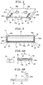
- Fig. 2 is a perspective view of a bottom surface side
of a slider shown in Fig. 1.
- Fig. 3 is a cross-sectional view showing an assembled
condition of the slider and a casing shown in Fig. 1.
- Fig. 4A is an enlarged cross-sectional view of a
primary part showing an engagement condition of an elastic
lock piece shown in Fig. 1.
- Fig. 4B is a partly enlarged cross-sectional view of
a primary part of the slider shown in Fig. 1.
- Fig. 5 is a perspective view of a slider in
accordance with another embodiment of the present aspect.
- Fig. 6 is a perspective view of a slider in
accordance with still another embodiment of the present
aspect.
- Fig. 7 is a perspective view of a slider in
accordance with still another embodiment of the present
aspect.
- Fig. 8 is a cross-sectional view illustrative of a
change in a depth direction of a groove of the slider in
accordance with the embodiment shown in Figs. 1 to 3 and
Fig. 7.
- Fig. 9 is a cross-sectional view illustrative of the
change in the depth direction of the groove of the slider
in accordance with the embodiment shown in Fig. 5.
- Fig. 10 is a cross-sectional view illustrative of the
change in a depth direction of a groove 25b of the slider
in accordance with the embodiment shown in Fig. 6.
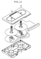
- Fig. 11 is an exploded outer appearance view of β CAM
cassette represented as a reference.
- Figs. 12A and 12B are a top surface view and a bottom
surface view of a lower half of the β CAM cassette shown in
Fig. 11, respectively.
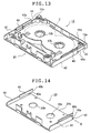
- Fig. 13 is a perspective view illustrative of a lower
half and a slider in one embodiment of a magnetic tape
cassette in accordance with a second aspect of the present
invention.
- Fig. 14 is a perspective view of the slider in
accordance with one embodiment of a magnetic tape cassette
of the present aspect.
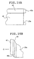
- Fig. 15A is a side elevational view enlarging and
showing the vicinity of a portion of a dust-proof wall
provided in the slider of the magnetic tape cassette
according to the present aspect in Fig.15A.
- Fig. 15B is a plan view showing the same portion.
- Fig. 16 is an exploded perspective view showing a
schematic structure of a magnetic tape cassette including a
slider formed through a molding method in accordance with a
third aspect of the present invention, in accordance with
one embodiment of a fifth aspect of the present invention.
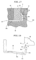
- Fig. 17 is a cross-sectional view showing a state
where a side wall portion of a slider is formed in
accordance with this embodiment.
- Fig. 18 is a front view showing a state when the side
wall portion rides over a side core when the slider is
molded in the embodiment.
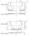
- Figs. 19A and 19B are a schematic back surface of a
molded article molded with a stamp in accordance with one
embodiment of a molded article stamping method in
accordance with a fourth aspect of the present invention
and a schematic cross-sectional view taken along the line
I-I, respectively.
- Figs. 20A and 20B are a schematic back surface of a
molded article molded with a stamp in accordance with one
embodiment of a molded article stamping method in
accordance with the present aspect and a schematic cross-sectional
view taken along the line II-II, respectively.
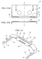
- Figs. 21A and 21B are a schematic back surface of a
molded article molded with a stamp in accordance with one
embodiment of a molded article stamping method in
accordance with the present aspect and a schematic cross-sectional
view taken along the line III-III, respectively.
- Fig. 22 is a perspective view enlargingly showing a
brake member in accordance with a fifth aspect of the
present invention shown in Fig. 16.
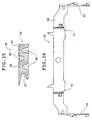
- Fig. 23 is a plan view of the brake member shown in
Fig. 22 as viewed from above.
- Fig. 24 is a bottom surface view of the brake member
shown in Fig. 22 as viewed from below.
- Fig. 25 is a cross-sectional view taken along the
line V-V of Fig. 23.
- Fig. 26 is a bottom surface view as shown in Fig. 25
and showing another example of the brake member according
to the present embodiment.
- Fig. 27 is a cross-sectional view showing a state of
the molding the brake member by molds in accordance with
the present embodiment.
- Fig. 28A is a perspective view of one embodiment of a
slider spring that is a specific example of a plate spring
according to a sixth aspect of the present invention.
- Fig. 28B is a developed view of the slider spring
before bending work.
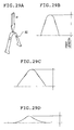
- Fig. 29A is a schematic view showing a method of
measuring a spring force.
- Figs. 29B, 29C and 29D are views illustrative of the
case where a spring opening angle is at approximately 30
degrees, the case where the spring opening angle is at
approximately 60 degrees and the case where the spring
opening angle is at approximately 160 degrees, respectively.
- Fig. 30A is a diagram showing a relationship between
bending angles of the slider spring shown in Fig. 28A and
the conventional slider spring and spring force at a first
loading point.
- Fig. 30B is a diagram showing a relationship between
the bending angles of the slider spring shown in Fig. 28A
and the conventional slider spring and spring force at a
second loading point.
- Fig. 31 is a view illustrative of the effect of the
overlapping prevention in the slider springs that is a
specific example of the plate springs of the present aspect.
- Fig. 32 is a perspective view showing a structural
example of a slider in the conventional tape cassette.
- Fig. 33 is an exploded perspective view showing
primary component members of the conventional magnetic tape
cassette.
- Fig. 34 is a side elevational view of the
conventional magnetic tape cassette.
- Fig. 35 is a perspective view illustrative of the
slider and the lower half of the conventional magnetic tape
cassette.
- Fig. 36 is a perspective view illustrative of the
slider and a body of the conventional magnetic tape
cassette.
- Fig. 37 is a plan view showing the slider shown in
Fig. 36.
- Fig. 38 is a cross-sectional view showing a state of
molds for molding a portion of a cross-section of a side
wall taken along the line VI-VI of Fig. 37.
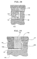
- Fig. 39 is a cross-sectional view showing a state of
molds for molding a portion of a cross-section of the side
wall taken along the line VII-VII of Fig. 37.
- Fig. 40 is a frontal view showing a state when the
side wall portion rides over a side core when the slider is
molded in the conventional molding method.
- Fig. 41 is a frontal view showing a state of
deformation of the slider in accordance with the
conventional molding method.
- Fig. 42 is a side elevational view showing the state
of deformation of the slider shown in Fig. 41.
- Fig. 43A is a schematic back surface view of a
magnetic tape cassette in the closing position of the
slider shown in Fig. 33.
- Fig. 43B is a schematic back surface view of the
magnetic tape cassette in the opening position of the same
slider.
- Figs. 44A and 44B are a schematic back surface view
of a conventional molded article provided with a stamped
portion and a schematic cross-sectional view taken along
the line VI-VI, respectively.
- Fig. 45 is a perspective view showing the
conventional brake member.
- Fig. 46 is a plan view showing the function of the
conventional brake member.
- Figs. 47A, 47B and 47C are side elevational views
showing the functions of the conventional brake member and
front lid, respectively.
- Fig. 48 is a cross-sectional view taken along the
line XI-XI line of Fig. 45.
- Fig. 49 is a perspective view showing another example
of the conventional brake member.
- Fig. 50 is Further a perspective view showing another
example of the conventional brake member.
- Fig. 51 is a view illustrative of an assembly of the
slider spring showing a main constituent example of the
conventional magnetic tape cassette.
- Fig. 52 is a perspective view illustrative of the
structure of the conventional slider spring.
- Fig. 53 is a view illustrative of an assembly of the
slider spring showing a main constituent example of the
conventional magnetic tape cassette.
- Fig. 54 is a view illustrative of improving a state
of the conventional slider springs.
-
BEST MODE FOR CARRYING OUT THE INVENTION
-
A magnetic tape cassette, its parts, a molding method
of the parts, a stamping method of molded article and a
molded article according o the present invention will now
be described in detail on the basis of a preferred
embodiment shown in the drawings.
-
First, an embodiment mode of a magnetic tape cassette
according to a first aspect of the present invention will
be described in detail with reference to Figs. 1 to 12.
-
Fig. 1 is a schematic exploded perspective view of a
magnetic tape cassette in accordance with one embodiment of
the present invention. Fig. 2 is a perspective view
showing a slider of the same tape cassette on a bottom
surface side. Fig. 3 is a cross-sectional view showing the
same tape cassette.
-
The magnetic tape cassette is provided with a flat
box-shaped casing 11 obtained by coupling an upper case
(hereinafter referred as an upper half) 10 and a lower case
(hereinafter referred to as a lower half) 12 and a slider
20 mounted slidably on the lower surface side of this
casing 11.
-
A magnetic tape is wound around hubs (not shown) on
both sides and accommodated in an interior of the above-described
casing 11. A central portion of a bottom portion
of a front portion in a loading direction D to the
recording and reproducing apparatus is removed together
with a front surface portion from a bottom surface 12a
formed in the above-described lower half 12 to form an
opening portion 12c for the tape loading. Further, the
front portion of the upper half 10 is opened at the front
surface portion in the same manner. A front lid 18 is
rotatably arranged to be upright on the front side of this
front surface opening portion and is opened/closed in
accordance with the loading to the recording and
reproducing apparatus.
-
A tape loading device (not shown) of the recording
and reproducing apparatus is insertable from below into the
opening portion 12c of the bottom surface of the above-described
lower half 12. The tape is drawn forwardly to
perform the recording and reproducing. Additionally, a
pair of drive shaft insertion holes 12b are opened on both
sides in the lower half 12.
-
The above-described slider 20 openes and closes the
bottom surface opening portion 12c of the lower half 12 of
the above-described casing 11 in accordance with the back-and-forth
sliding movement of the tape cassette in the
loading direction D. This slider 20 is composed of a flat
plate portion 20a composed of a bottom surface in parallel
with the bottom surface 12a of the lower half 12 and side
wall portions 20d in an upright condition on both sides.
The overall structure is integrally formed of synthetic
resin.
-
Engagement sliding portions 20e serving as pull-apart
preventing pieces from extending upwardly are provided on
the above-described side wall portions 20d and as shown in
Fig. 3, are insertable into slits in coupling portions
defined between the upper half 10 and the lower half 12 to
be slidable back and forth with their movement being
limited.
-
A length of the flat plate portion (bottom surface)
20a of the above-described slider 20 in the sliding
direction is formingly set to be shorter than the length of
the casing 11 in the back-and-forth direction. When the
slider is moved forwardly, the front end portion is
coincide to the front end position of the casing 11 to
close the above-described opening portion 12c. When the
slider is moved backwardly, the slider fully open the
opening portion 12c. Then, the driving shaft insertion
holes 20b are opened in the slider 20 in the same manner in
the position identical with that of the drive axle
insertion holes 12b of the lower half 12. Additionally,
the center position of these drive shaft insertion holes
20b is formed to be offset rearwardly of the centerline S
in a direction perpendicular to the sliding direction of
the slider 20.
-
A lock mechanism for locking the above-described
slider 20 in each of the opening position and the closing
position is provided in the lower half 12. This lock
mechanism is composed of elastic lock piece 13 of the lower
half 12 and through- holes 30, 31 of the slider 20. The
above-described elastic lock pieces 13 are integrally
formed in one position or more in the bottom surface 12a of
the above-described lower half 12 (one on each side in the
case shown).
-
As shown in Fig. 4A, the proximal ends of the elastic
lock pieces 13 are connected to the lower half 12, and the
distal end portions are separated from the lower half 12
and elastically deformable. Hook-shaped engagement head
portions 13a are formed downwardly at the tip ends to be
swingable up and down. These engagement head portions 13a
are provided to project further downwardly from the bottom
surface 12a of the lower half 12 and to be engageable with
the through- holes 30, 31 of the slider 20.
-
The two through- holes 30 and 31 are formed in a
rectangular shape through the flat plate portions 20a of
the slider 20 back and forth of each of the right and left
sides. Namely, the front side through-hole 30 engaged with
the engagement head portion 13a in the position where the
slider 20 opens the opening portion 12c and moved
backwardly and the rear side through-hole 31 engaged with
the engagement head portion 13a in the position where the
slider 20 closes the opening portion 12c and moved
forwardly are provided on each side and the movement of the
slider 20 is locked by the engagement of the two components
in the respective positions.
-
The locking state of engagement between the
engagement head portion 13a of the above-described elastic
lock piece 13 and the above-described through- holes 30, 31
is released using a push-up piece 38a of a lock release
member 38 (see Fig. 4A) provided in the recording and
reproducing apparatus into which the tape cassette is
loaded. This lock release member 38 is guided by a guide
groove 32 composed of a recess groove having a rectangular
shape in cross section and formed in the bottom surface of
the slider 20. The push-up piece 38a that has been
elevated is brought into contact with the engagement head
portion 13a of the elastic lock piece 13 engaging with the
above-described through- hole 30, 31 opened being coincide
to this guide groove 32, thereby releasing engagement.
Additionally, the front end portion of the above-described
guide groove 32 is formed to spread over in the right and
left direction (see Fig. 2).
-
The above-described guide groove 32 is provided in an
elongated shape in the loading direction D of the tape
cassette. An axle in the longitudinal direction thereof is
formed at a position substantially overlapped with an axle
of the above-described elastic lock piece 13 in the loading
direction D. The rear end portion of this guide groove 32
is provided particularly forwardly of the centerline S (see
Fig. 2) perpendicular to the sliding direction of the
slider 20 in the position forward from the center of the
drive axle insertion holes 20b.
-
A convex region 34 having such a height that comes
into sliding contact with a rear surface (lower surface in
the drawing) of the bottom surface 12a of the lower half 12
is formed on the top surface of the flat plate portion 20a
of the slider 20 in a peripheral portion including the
molded range of the guide grooves 32 and the above-described
through- holes 30, 31, that is, the surface on the
side facing the bottom surface of 12a of the lower half 12
of the slider 20, so as to surround a portion on which the
guide grooves 32 are projected. Then, the above-described
slider 20 is brought into sliding contact with the rear
surface of the bottom surface 12a of the lower half 12
through above-described convex region 34.
-
The above-described convex region 34 projectingly
extends in the form of a plurality of convex groove shapes
radially about, for example, a resin injection gate 39
sideways or obliquely backwardly from the front side tip
end of the slider 20. The formation region is that the
rear extending end 34a of the convex region 34 is within
such a region that does not exceed the above-described
centerline S in the direction perpendicular to the sliding
direction of the slider 20 (See Fig. 1). Further, this
convex region 34 includes the portion obtained by
projecting the above-described substantially rectangular
guide grooves 32.
-
By forming the above-described convex region 34,
thickness of the flat plate portion 20a of the slider 20 is
thicker than that of the other portion in the peripheral
portion except for the guide grooves 32 and is smaller in
the portions of the guide grooves 32. In order to prevent
deformation such as the "warpage" of the slider 20 due to
such a change in thickness, in the tape cassette in
accordance with this embodiment, a recess-shaped portion
(recess portion) for preventing the "warpage" such as
described below is provided.
-
That is, as shown in Figs. 1 to 3, particularly as
shown in a partially enlarged view of Fig. 4B, a recess-shaped
portion (recess portion) having a triangular shape
in cross-section, i.e., a warpage preventing groove
(hereinafter simply referred as a groove) 36 is formed over
a full length of the slider 20 in the sliding direction in
a thin portion of a rear surface of a surface where the
above-described guide grooves 32 are provided (i.e., the
top surface in Figs. 1 and 3 and the lower surface in Fig.
2).
-
Each groove 36 like this is provided whereby the
"warpage" of the slider 20 due to the change in thickness
of the portion of the above-described guide grooves 32 is
offset to make it possible to provide a molded article
without any "warpage" as a whole.
-
Additionally, the distal ends of the engagement head
portions 13a engaging with the above-described through- holes
30, 31 are located within the guide grooves 32 (in
the height direction) so as not to project downwardly from
the lower surface of the slider 20.
-
A retainer member 33 at which a spring (not shown)
for biasing the slider 20 in the closing direction is
hooked and which has the resin injection gate 39 upon
molding is provided in the front end central portion of the
slider 20.
-
Assist projections 35 having tip ends that may be
brought into contact with the bottom surface of the lower
half 12 are formed on the right and left sides on the top
surface, in the vicinity of the rear end portion of the
slider 20 to prevent rattling upon sliding movement from
generating. These assist projections 35 have the same
height as that of the above-described convex region 34.
Further, the tip ends of these assist projections 35 may be
bent surfaces, such as planar surface and spherical shape.
Additionally, with respect to the height of the above-described
convex region 34, for example, the projection
amount from the peripheral portion is in the range of
approximately 0.05 to 0.3 mm.
-
The normal general operation of the above-described
tape cassette will be hereinafter explained. First of all,
before loading to the recording and reproducing apparatus,
the slider 20 is in the forward position to close the
bottom surface opening portion 12c. Under this state, the
engagement head portions 13a of the elastic lock pieces 13
are locked so that the engagement head portions 13a are out
of engagement with the rear side through-holes 31 not so as
to perform the opening operation.
-
Accompanying with the loading to the recording and
reproducing apparatus, the lock release members 38 are
inserted from the front end portions of the guide grooves
32 and release the engagement of the engagement head
portions 13a engaging with the rear side through-holes 31
by operation of the push-up pieces 38a, to make the slider
20 movable and to move the slider 20 rearwardly relative to
the casing 11, accompanying with the loading operation to
open the bottom surface opening portion 12c. The
engagement head portions 13a of the elastic lock pieces 13
are engaged with the front side through-holes 30 at the
backward position to lock the release position. The tape
loading device is inserted into the opened opening portion
12c to draw out the tape forwardly to make it possible to
record and reproduce.
-
When the magnetic tape cassette is taken out after
usage, the lock release member 38 is moved relatively
forwardly to release the engagement of the engagement head
portions 13a of the elastic lock pieces 13 engaging the
front side through-holes 30 by the operation of the push-up
pieces 38a. The slider 20 is moved in the closing
direction by the biasing force of the spring to close the
opening portion 12c. In such movement of the slider 20,
the above-described grooves 36, the convex region 34 and
the assist projections 35 are formed to obviate the
problems such as the "warpage" upon molding or the like and
to keep sliding characteristics splendid.
-
That is, first, with respect to the above-described
convex region 34, because the convex portion 34 is formed
so that the thickness of the peripheral portion of each
guide groove 32 is thinkened, the resin is caused to flow
smoothly earlier due to the portion of the guide groove 32.
For this reason, it is possible to suppress the problems of
molding faults such as strains or "warpage" due to the
fluidization faults.
-
Further, with respect to the grooves 36, unless these
are provided, because the portion of the guide groove 32 is
thin, upon molding the slider 20, the resin fed from the
above-described resin injection gate 39 flows around so as
to bypass this portion. At this portion, the resin flow is
largely changed. The flow onward has large turbulence and
thus the "warpage" occurred in the slider 20. Accordingly,
it is possible to think that the provision of the grooves
36 had an effect to cancel turbulence of the resin flow by
the guide groove 32.
-
Fig. 5 shows another embodiment in which the groove
36a is in the form of a rectangular shape. The
construction other than this is the same as the above-described
embodiment. Additionally, in this embodiment,
the same reference numerals are used to indicate the like
components and the explanation therefor will be omitted.
-
Fig. 6 shows still another embodiment in which the
groove 36b is in the form of a semicircular shape. The
construction other than this is the same as the above-described
embodiment. Additionally, Further in this
embodiment, the same reference numerals are used to
indicate the like components and the explanation therefor
will be omitted.
-
Fig. 7 shows still another embodiment in which the
like groove 36 as shown in Fig. 1 is added to the slider 20
shown in Fig. 32. Additionally, in this embodiment, the
same reference numerals are used to indicate the like
components and the explanation therefor will be omitted.
-
In the foregoing embodiments, the grooves 36 (36a,
36b) are formed in the full width in the sliding direction
of the slider 20. However, the present invention is not
limited thereto. For example, the grooves 36 (36a, 36b)
may have a length corresponding to the portion where the
above-described guide grooves 32 are present in the sliding
direction of the slider 20.
-
Further, the depth of the grooves 36 shown in Figs. 1
to 3 and Fig. 7, the grooves 36a shown in Fig. 5 and the
grooves 36b shown in Fig. 6 can be embodied in various ways
as shown in cross-sections of Figs. 8 to 10.
-
That is, it is possible to effectively use one having
a uniform depth as shown in Fig. 8, one having a depth that
is changed in a constant rate as shown in Fig. 9 or one
having a depth that is changed stepwise as shown in Fig. 10.
-
In these cases, the depth of the groove is deeper on
the front side in the above-described loading direction D
into the recording and reproducing apparatus and is
shallower on the rear side. Further, in the case where the
depth is to change stepwise, in view of the fluidization of
the resin upon molding, for example, in the case where the
depth is divided into three steps, it is preferable that a
position p where the first step is formed is in a rear end
portion of the convex region 34 (see Figs. 1, 5 and 6) and
a position 9 where a second step is provided is in the rear
end portion of the drive axle insertion holes 20b (see the
same).
-
In addition to the specific examples shown in Figs. 8
to 10, it is possible to use one having a depth that is
changed in a bent manner or it is possible to select ones
variously with respect to the number of the steps or a
height thereof in the case where the depth is changed
stepwise.
-
Further, of course, these factors may be used in
combination for a specific shape and it is possible to
apply the shape variously in view of the fluidization of
the resin upon molding.
-
Additionally, one indicated by reference numeral 37
in Figs. 1 to 6 is a tilt preventing groove for reducing
deformation after molding the side wall portions 20d on
both sides of the slider 20 (referred as "tilt" because the
wall portions are normally tilted inwardly). Further, the
shape of the tilt preventing groove 37 is not limited to a
circular shape as shown in Figs. 1 to 3 and Figs. 5 and 6
but it is possible to use a somewhat angular shape as shown
in Fig. 4B.
-
The substantially rectangular concave guide grooves
that have been described above are provided Further in
other magnetic tape cassettes, such as a β CAM cassette (L-type)
used in, for example a broadcasting station. The
purpose of these grooves are to be used for positioning
with respect to the apparatus for recording and reproducing
in the same manner as in the cassette according to the
present invention.
-
Further with respect to this β CAM cassette, because
the formation of such grooves encounters the problems as
described above, it is possible to apply the structure
according to the present invention thereto.
-
Fig. 11 is an exploded outer appearance view of the
above-described β CAM cassette. Further, Figs. 12A and 12B
are plan views of the lower half thereof. Fig. 12A is a
top surface view and Fig. 12B is a lower surface view.
Ones indicated by reference character 32a in Fig. 12B are
grooves corresponding to the guide grooves 32 described
above.
-
The magnetic tape cassette according to the first
aspect of the present invention is basically constructed as
above-described.
-
One embodiment of a magnetic tape cassette according
to a second aspect of the present invention will now be
basically described with reference to Figs. 13 to 15.
-
The magnetic tape cassette according to the second
aspect of the present invention (hereinafter simply
referred to Further as a cassette) is mainly composed of an
upper half, a lower half coupled with the upper half to
form a casing, a slider fitted slidably in the back-and-forth
direction of the casing along the bottom surface and
the side surfaces of the lower half and a magnetic tape
accommodated in the casing. The slider has engagement
sliding portions, fittingly inserted into the sliding
grooves formed between right and left side walls of the
upper half and right and left walls of the lower half, at
an upper end inner edge of the both right and left side
walls thereof. The engagement sliding portions are
elongated members having lower surfaces engaging and
slidingly contacting right and left side wall top surfaces
of the lower half.
-
In the cassette according to this aspect, this
engagement sliding portions have dust-proof walls with the
rear ends being formed to extend toward the rear side wall
of the lower half. These dust-proof walls are constructed
to close a gap between the lower half and the upper half in
the inner deep portion of the opening portion formed in the
lower portion on each side of the casing between the rear
side wall of the lower half and the rear ends of the right
and left side walls of the slider when the slider is in the
forward position.
-
The height of the dust-proof walls, i.e., the height
in the vertical direction (in a direction from the lower
half to the upper half) is not less than such a height that
the walls close at least the gap between the lower half and
the upper half in the inner deep portion of the opening
portion and that the walls do not contact the upper half.
Further, the length of the dust-proof walls, i.e., the
length in the horizontal direction of the dust-proof walls
(in a direction from the rear ends of the engagement
sliding portions to the rear side wall of the lower half)
is selected so that in the rearward position of the slider,
i.e., when the side ends of the dust-proof walls are
brought into contact with the rear side wall of the lower
half, the front opening portion of the lower half is opened
for making possible to keep the magnetic tape traveling the
front opening portion in the readout or recording operation
by the recording and reproducing apparatus. When the slider
is in the forward position, the dust-proof walls close the
gap formed between the lower half and the upper half in the
inner deep portion of the opening portion formed in the
lower portion of each side of the casing between the rear
side wall of the lower half and the rear ends of the right
and left side walls of the slider. At this time,
corresponding to the length of the dust-proof walls, when
the slider is in the forward position, falling without the
range in contact with the outer contour of the maximum
winding region of the magnetic tape, side walls can be
provided continuous with the rear side wall of the lower
half with their end overlapping with the side ends of the
above-described dust-proof walls to close the gap formed
between the upper half and the lower half in the inner deep
portion of the opening portion.
-
Further, in the magnetic tape cassette according to
this aspect, when the side ends of the dust-proof walls are
in contact with the rear side wall of the lower half, guide
holes corresponding to the drive shaft insertion hole of
the rewiding side hub and the drive shaft insertion hole of
the feed side hub of the lower half are formed in the
bottom surface of the slider.
-
The magnetic tape cassette according to the second
aspect of the present invention will now be described in
more detail with reference to one specific example shown in
Figs. 13 to 15.
-
Fig. 13 is a perspective view showing a lower half 12
and a slider 20 fitted slidably to the lower half 12 in a
specific example of the cassette according to this aspect.
Additionally, the upper half is the same as that shown in
Fig. 33 and hence is omitted.
-
As shown in Fig. 14, the slider 20 has a bottom
surface 20a made of a planar plate portion and side wall
portions 42, 42 formed in an upright condition at both
right and left ends of the bottom surface 20a. Drive shaft
insertion holes (guide holes) 20b, 20b corresponding to a
drive shaft insertion hole 12b of the rewiding side hub and
a drive shaft insertion hole 12a of the feed side hub of
the lower half 12 shown in Fig. 13 are formed in the bottom
surface 20a. Further, elongated engagement sliding
portions 40, 40 are arranged in upper end inner edges of
side wall portions 42, 42 of the slider 20, respectively.
-
Lower surfaces 40a, 40a of the engagement sliding
portions 40, 40 engage with and slidingly contact with top
surfaces on the right and left side walls of the lower half
12.
-
In the cassette according to this aspect, dust- proof
walls 40b, 40b extending toward the rear side wall 12d of
the lower half 12 are provided at the rear ends of the
engagement sliding portions 40, 40 of the slider 20.
-
The slider 20 having these dust- proof walls 40b, 40b
is fitted in the lower half 12. Furthermore, in the
cassette according to this aspect provided with the upper
half, the engagement sliding portions 40, 40 are inserted
into sliding grooves formed between the right and left side
walls of the lower half and the upper half.
-
Tapers (slants) that are smaller toward the rear side
walls 12d may be formed on four surfaces other than the
surfaces confronting the rear side wall 12d of the lower
half 12, in the dust- proof walls 40b, 40. The slider is
shown in Fig. 15A that is an enlarged side elevation view
of the vicinity of the dust-proof wall as viewed from in a
direction indicated by the arrow B in Fig. 14, and in Fig.
15b that is a plan view thereof. In this case, Fig. 15A is
a side elevation view of the vicinity of the dust-proof
wall as viewed in a direction indicated by the arrow C of
Fig. 15B.
-
As shown in Figs. 15A and 15B, the four surfaces
other than the surfaces confronting the lower half rear
side wall of the dust-proof wall 40b is formed to be
gradually smaller in size toward the rear side wall
(rightward in Fig. 15A and downwardly in Fig. 15B). At
this time, the tapers are formed Further in the dust-proof
wall 40b in the same manner.
-
When the slider is molded using molds, the dust-proof
wall is formed using a slide core. In the case where the
dust-proof wall is in a rectangular parallelepiped shape
obtained by extending the engagement sliding portion
without any modification, when the slide core is slid and
removed, the wear scar (abrasion) is likely to occur in the
dust-proof portion. There is a fear that this leads to the
appearance defectives. Further, because the slide core per
se is a small bock, it is impossible to provide a cooling
circuit in its interior. There may be a case where this
causes adverse effects in the molding cycle where the mold
cooling time is extended, or the mold-ability may be
deteriorated.
-
However, when the tapers are formed in the dust-proof
walls as described above, it is possible to shorten a
portion corresponding to a cooling time of the molding
cycle and it is possible to obtain a good outer appearance
without degradation of mold-ability.
-
As shown in Fig. 13, in the cassette according to
this aspect, when the slider 20 is in the forward position,
the opening portions 44, 44 are formed in the lower
portions on both sides of the casing between the rear side
wall 12d of the lower half 12 and the rear ends 42a and 42a
of the side wall portions 42, 42 of the slider 20. In
these opening portions 44, 44, the dust- proof walls 40b,
40b overlap with side walls 12e, 12e of the lower half 12
formed in an upright condition continuously with the rear
side wall 12d of the lower half 12, thereby closing a gap
formed between the lower half 12 and the upper half 10 to
prevent the dust or foreign matters from entering from the
opening portions 44, 44.
-
These dust- proof walls 40b, 40b serve to close the
gap formed between the lower half 12 and the upper half 10
in the inner deep portions of the opening portions 44, 44.
In the conventional case, the side walls 12e, 12e of the
lower half 12 are formed so that the tip ends extend to the
winding region (the portion indicated by the dotted lines 2
in fig. 13) of the magnetic tape continuously with the rear
side wall 12d of the lower half 12 in order to close the
gap in the inner deep space of the opening portions 12a and
12b. With the dust-proof walls, the side walls 12e, 12e can
be arranged at positions where the side walls are out of
contact with the winding region. It is thus possible to
keep the maximum region as the winding region.
-
Further, in the conventional cassette, in order to
keep the rewinding region and in order not to come into
contact with the winding region, the corresponding portions
in the side walls 12e, 12e of the lower half 12 has to be
made thin. Upon molding the lower half 12, the portion
where the molten resin is hardly caused to flow is formed
in the cavity to cause a problem in molding. However, in
the cassette according to the present aspect, such a
problem is overcome. This is particularly advantageous in
molding.
-
Further, in the case where tapers that are decreased
toward the rear side wall 12d of the lower half 12 are
formed in the dust- proof walls 40b, 40b as described above,
Further in formation of the slider 20, it is possible to
obtain a splendid outer appearance without degrading mold-ability.
-
The magnetic tape cassette in accordance with the
second aspect of the present invention is basically
constructed as described above.
-
Subsequently, one embodiment of a molding method of a
slider of a magnetic tape cassette according to a third
aspect of the present invention will now be described in
detail with reference to Figs. 16 to 18.
-
Fig. 16 is a schematic exploded perspective view of a
magnetic tape cassette including a slider formed through a
molding method in accordance with a third aspect of the
present invention.
-
The magnetic tape cassette is composed mainly of an
upper half 10 and a lower half 12, and a magnetic tape 16
wound around take-up hubs 14 is accommodated therebetween.
A front lid (lid) 18 for covering and protecting the
magnetic tape in no use of the cassette is rotatably
mounted about a pivot shaft 10a on a front surface side of
the upper half 10. Further, a slider 20 for closing the
exposed portion of the case lower side to improve the seal-ability
is mounted slidably back and forth on the lower
surface on the outer side of the lower half 12.
-
In no use of the cassette, in order to prevent the
magnetic tape 16 wound-up around the take-up hubs 14, from
being loosened, a brake member 22 is additionally provide
to the upper half 10. The brake member 22 causes brake
pieces 22a to engage with gears 14a provided on upper
portions of the take-up hubs 14, thereby prohibiting
rotation of the take-up hubs 14 and preventing the magnetic
tape 16 from loosing. The brake member 22 is biased to a
position where the brake pieces 22a engage with the gears
14a in no use of the cassette by a brake spring 24. The
brake spring 24 is retained at a projection 10b formed in
the upper half 10.
-
The lower half 12 has reel axle insertion holes 12b,
12b for insertion of the reel shaft into the cassette case
in no use of the cassette in a rectangular bottom surface
12a.A V-shaped bent wall-shaped member 12f is provided
along the magnetic tape 16 wound around the take-up hubs 14
in the lower half, and a plate spring (slider spring) 26
that is a biasing means for forwardly biasing the slider 20
is fitted in the central portion thereof.
-
The slider 20 has reel shaft insertion holes 20b, 20b
for inserting the reel axle into the cassette case in use
of the cassette into a rectangular bottom surface
(horizontal surface) 20a. A rib 20c for receiving the
biasing force of the plate spring 26 is standingly disposed
on the front side of the bottom surface 20a of the slider
20. Further, the slider 20 has side walls 20d, 20d
standingly disposed, vertically in the front surface 20a on
both right and left ends of the bottom surface 20a thereof
to form a U-shape. Engagement sliding portions (dust-proof
wall portions) 20e, 20e for engaging the lower half 12 to
prevent the slider 20 from falling apart, for enhancing the
dust-proof effect and for smoothly moving the slider 20 are
provided at partial upper ends of the side walls 20d, 20d.
-
The slider 20 is slidingly moved back and forth of
the cassette in contact with the bottom surface 12a of the
lower half from below. When the cassette is loaded in the
deck, the slider 20 is positioned automatically rearwardly
by action of the device within the deck. However, in no
use of the cassette, the slider 20 is positioned in the
forward position using the plate spring 26 provided in the
lower half 12. When the slider is located in the forward
position, the space of the center front portion of the
above-described lower half 12 and the reel shaft insertion
hole 12b, 12b are covered using the bottom surface 20a of
the slider 20 for dust-proof. Further, when the slider 20
is located backwardly, the space of the central front
portion of the above-described half 12 is opened and the
reel insertion holes 20b, 20b provided in the bottom
surface 20a of the slider 20 are identified with the reel
shaft insertion holes 12b, 12b of the bottom surface 12a of
the above-described lower half 12.
-
In this aspect, when the slider is to be molded,
because the side walls of the slider are tilted inwardly
and the bottom portion is prevented from being expanded,
although this is not preferable inherently, when the molds
are opened, the side walls of the slider are intentionally
molded such that the walls are formed riding over the side
core. Thus, it is possible to impart the reverse warpage
to the normal one of the slider, as a result of which it is
possible to obtain the molded article that has a good
dimensional precision (warpage).
-
Further, then, in order to avoid the scar in the
slider side walls, the adverse affect onto the outer
appearance of the slider is avoided.
-
For this reason, in the embodiment, as shown in the
cross-sectional view of Fig. 17, when the side wall portion
of the slider 20 is molded using a main core (movable side
mold 45, a cavity (stationary side mold) 46, a slide core
(movable side mold) 47 and a side core movable side mold)
48, a round is given (R-addition) as indicated by reference
numeral R at upper and lower ends of longitudinal surfaces
formed by the side core 48. Thus, when the molds are
opened, the side walls 20d (dust-proof wall portions 20e of
the rear ends of the engagement sliding portions) may
smoothly and surely ride over the side core 48.
-
Then, in order not to remain abrasive trace in the
lateral direction on the vertical side surfaces of the
cores (side core and main core) of the portions
corresponding to the both right and left side walls, it is
preferable that the polishing state is improved or the
removal slant angle is taken so that the mold releasing
propensity from the molds (cores) of the slider 20 is
improved.
-
Further, when the molds are opened, in Fig. 17, first
of all, the slide core 47 is removed laterally (in the
forward direction of the paper surface of the drawing).
Therefore, as shown in Fig. 18, when the molds are opened,
the side walls 20d are not retained by the slide core 47
and the side walls 20d are only held by the main core 45 in
the same manner as in Fig. 6 in the portions where the
engagement sliding portions 20e are not present.
Accordingly, the force for holding the side walls 20d is
decreased or almost eliminated.
-
Thus, in this embodiment, when the molds are opened,
the side wall portions have almost no force for holding to
the core side and are held in a floating condition, whereby
the side wall portions are more likely to ride over the
side core 48. Further, as described above, because the
round portions are given to the upper and lower ends of the
vertical surface of the side core 48 (R-bevel shape), when
the side wall portions ride over the side core 48, the
outer appearance of the slider 20 may be kept in a good
state without any scar, curl or the like.
-
Thus, in this embodiment, when the molds are opened,
because the side walls 20d of the slider 20 are kept under
the condition riding over the side core 48, it is possible
to obtain the correction effect to the warpage of the
molded article in which the bottom surface is likely to
expand and the side walls are likely to tilt inwardly.
This is because the core side (main core 45) of the bottom
20a portion of the slider 20 is kept at a temperature of
the mold (core), whereas the cavity 46 on the opposite side
is kept away from the mold and cooled down under the
deformed state.
-
Additionally, in this case, as shown in Fig. 18, a
slit-shaped tilt preventing groove 20f may be provided at
the proximal end portion of the side wall 20d thereby
improving correction effect.
-
Further, when a part of the side wall portion is
formed by the slide core as stated in the present
embodiment, as shown by reference character P in Fig. 17,
it is preferable that the side core 48 and the slide core
47 are in abutment (parting) with each other at the center
of the side wall rib (engagement sliding portion, dust-proof
wall portion 20e). This is because when the side
core 48 and the slider 47 are abutment with each other on
the inside of the side wall rib or at the outer side end
thereof, it is impossible to make round (R) or bevel or
chamfer (C) so that the edge of the side wall rib of the
slider 20 is damaged. Further, the lower half 12 and the
upper half 10 are brought into contact with the assembled
brake arm portion to cause a defect such as an assembling
fault (misalignment in assembling).
-
The molding method of a slider of a magnetic tape
cassette according to the third aspect of the present
invention is basically below-explained.
-
A molding article stamping method in accordance with
a first embodiment of a fourth aspect of the present
invention and one embodiment of the molded article
according to the second aspect will now be described in
detail with reference to Figs. 19A to 21B.
-
Figs. 19A and 19B are a schematic back surface of a
molded article molded with a stamp in accordance with one
embodiment of a molded article stamping method in
accordance with a fourth aspect of the present invention
and a schematic cross-sectional view taken along the line
I-I, respectively. Figs. 20A and 20B are a schematic back
surface of a molded article molded with a stamp in
accordance with another embodiment of a molded article
stamping method in accordance with this aspect and a
schematic cross-sectional view taken along the line II-II,
respectively. Figs. 21A and 21B are a schematic back
surface of a molded article molded with a stamp in
accordance with one embodiment of a molded article stamping
method in accordance with this aspect and a schematic
cross-sectional view taken along the line III-III,
respectively.
-
The example shown is one in which the molded article
stamping method according to the present invention is
applied to a slider 104 that is one of the constituents of
one embodiment of the magnetic tape cassette shown in Fig.
33. Accordingly, the structure and effect of the slider
shown are same as described above.
-
As shown in Figs. 19A and 19B, the slider 20 is a
substantially U-shaped plastic molded article having at
parts a bottom surface 20 formed of a thin plate. Two
position display portions 50, 50 are provided on the back
surface of the bottom surface 20a. Each display portion 50,
50 is formed of a groove portion 52, 52 that is a recess
groove having both ends rounded and a stamp portion 54, 54
molded with letters "MADE IN JAPAN" or "FUJI PHOTO FILM" in
a convex manner within the groove portion 52, 52.
-
In the above-described example, the U-shaped slider
is exemplified as the plastic molded article. However, the
present invention is not limited thereto. It may be
applied to any plastic molded article that has at parts a
thin plate portion. It is Further possible to use a flat
plate made only of a thin plate portion. It is possible to
implant a plurality of plates from a thin plate portion.
For example, it is possible to use a variety of molded
members having a thin plate portion such as an upper half,
a lower half, a front lid or the like for constituting a
magnetic tape cassette.
-
It is possible to exemplify a DDS, a DAT, a video
tape cassette or the like as a magnetic tape cassette.
Further, the magnetic tape cassette is not limited to a
two-reel type magnetic tape cassette but may be a one reel
type magnetic tape cassette.
-
In the present invention, a portion made of a thin
plastic plate such as a bottom surface 20a, for example,
means the thin plate portion. If the thickness of 50% or
more of the plate surface area of the thin plate portion is
not greater than 1.5 mm, more particularly 1 mm, the
balance of dimensional precision of the present invention
is remarkable in comparison with the balance of the
dimensional precision of the conventional molded article.
-
Further, material of the plastic molded article is
not particularly limited.
-
In the foregoing examples, the groove having a flat
surface shape rounded at both ends is exemplified as the
groove portion 52. However, the present invention is not
limited thereto but it is possible to use any shape. For
example, it is possible to use a square, a rectangular
shape, a circular shape, an oblong shape or the like as a
flat surface shape and it is possible to form the groove
portion into an elongated groove portion and to round this
groove. For example, it is possible to take a semicircular
shape or a semi-elliptical shape or to bevel the corners.
Further, the groove portion may be continuous to straddle
the centerline A-A to be described later and a plurality of
the groove portions may be provided at intervals. Further,
it is possible to extend the groove in one or more stages.
Further, it is possible to further provide the groove
portion 52 in the groove portion 52.
-
The groove portions 52, 52 that are the elongated
recess-shaped grooves are provided symmetrically with
respect to the centerline A-A in a direction where the
grooves 52, 52 are extended, i.e., in the longitudinal
direction. Thus, even if the strain occurs in the molded
article, because the groove portions 52, 52 are provided
symmetrically with respect to the centerline A-A, the
balance of the dimensional precision is symmetrical with
respect to the centerline A-A. For this reason, as
described above, when the slider 20 is moved in the closing
position direction and is brought into contact with the
wall of the lower half, the contact portion is symmetrical
with respect to the centerline A-A, so that there is no
rattle in the slider 20.
-
Accordingly, the position where the groove 52 extends
may be any plate if it is symmetrical with respect to the
centerline A-A in the longitudinal direction of the bottom
surface 20a. For example, as shown in Figs. 19A and 19B,
the grooves 52, 52 may be provided symmetrically with
respect to the centerline A-A without straddling the
centerline A-A. Further, as shown in Figs. 20A and 20B,
the groove portion may be provided to intersect with the
centerline A-A and symmetrically with respect to the
centerline A-A. In this case, from a view of view that the
rattle is more effectively prevented, it is preferable that
the sum of the lengths of the groove portions 52 extending
in the same line in the longitudinal direction is 50 % or
more of the full length in the longitudinal direction of
the bottom surface 20a in the formation position of the
groove portion 52.
-
As shown in Figs. 21A and 21B, it is possible to form
the groove portion 52 to intersect with the centerline A-A
and to extend in the full length of the thin plate portion
in the longitudinal direction. In this case, the
dimensional precision becomes best.
-
In the present invention, the groove portion 52
extends in parallel with the longitudinal direction. The
present invention is not limited thereto. It is sufficient
to provide the groove portion 52 symmetrically with respect
to the centerline A-A in the longitudinal direction.
Therefore it is possible to provide the groove portion 52
to have an angle relative to the longitudinal direction.
-
Further, in the molded article having a plurality of
longitudinal directions, in assembling or using the molded
article, depending upon the direction in which the molded
members or the molded article and another member, for
example, the molded article and the member installed in the
recording and reproducing apparatus are brought into
contact or into sliding contact with each other, the
longitudinal direction is suitably determined. It is
possible to provide the groove portion 52 so that the
groove portion 52 is symmetrical with respect to the
centerline in this direction.
-
It is preferable that depth of the groove of the
groove portion 52 is not greater than 20% of the plate
thickness of the portion occupying 50% or more of the plate
surface area of the bottom surface 20a and most preferably
not greater than 10%.
-
In the foregoing example, the stamp portion 54
stamped with letters representing a production country and
a name of a maker in a convex manner is provided within the
groove portion 52. However, the present invention is not
limited thereto. It is possible to use letters, figures,
drawings, patterns or the like. For example, it is
possible to use a CI mark, a production country, a name of
a maker, a production name, a model, a size, a logotype
mark, a production place, a catch phrase or the like.
-
The position where the stamp portion is provided may
be any place in the groove portion 52. In the case where a
plurality of groove portions 52 are provided, it is
sufficient to provide the stamp portion 54 within at least
one of the groove portions 52. As shown in Figs. 19A to
21B, it is preferable to provide the stamp portion in the
symmetrical position with respect to the centerline A-A.
-
It goes without saying that the letters, figures or
the like represented by the stamped portion 54 is not
always necessary to be symmetrical with respect to the
centerline A-A.
-
Because it is necessary to overcome the conventional
problem to prevent the hook, it is preferable that a height
of the molded portion of the stamp portion 54 is
substantially equal to or less than a depth of the groove
of the groove portion 52.
-
The molded article with the stamp portion has been
described. A molded article stamping method in accordance
with the first aspect of the present invention will now be
described.
-
The stamping method of the molded article according
to the present invention is to display the stamp on the
surface of the molded article by molding the above-described
molding material using plastic molds provided
with concave and convex patterns on the stamp surface in
advance, so that the above-described groove portion and
stamp portion can be provided onto the surface of the thin
plate portion of the plastic molded article.
-
Here, in order to further improve the dimensional
precision, it is preferable to provide a cooling unit so as
to be symmetrical with respect to the centerline in the
longitudinal direction of the thin plate portion.
-
Here, the sculptured surface is not directly provided
in a mother mold but may be provided in another member and
fitted in the mother mold in a so-called insert core
molding manner. Further in this case in the same manner,
an insert core is formed so that a groove portion may be
provided symmetrically with respect to the centerline in
the longitudinal direction of the thin plate portion so as
to obtain a molded article having the above-described shape.
-
Further, it is preferable to provide the cooling
means in the insert core. In the case where the cooling
unit is not provided in the insert core, it is preferable
to provide the cooling means symmetrically with respect to
the longitudinal direction of the thin plate portion in
order to further improve dimensional precision.
-
The method of molding according to the present
invention is not particularly limited. It is possible to
exemplify a general molding method using molds in which the
above-described display portion may be provided on the
surface of the plastic molded article such as a compression
molding, a transfer molding, an injection molding, a blow
molding and the like.
-
The mold provided with the above-described sculptured
surface is used, or the mold into which the insert core is
fitted and provided with the sculptured surface is used and
the molding material is molded through the general molding
method whereby it is possible to mold the molded article
with a good balance of the dimensional precision without
any rattle or resin wear in assembling or using the molded
article with a desired integral display section.
-
The molding stamping method and the molded article
according to the fourth aspect of the present invention is
been thus constructed.
-
An embodiment of a magnetic tape cassette according
to a fifth aspect of the present invention will now be
described in detail with reference to Fig. 16 and Figs. 22
to 27.
-
The magnetic tape cassette according to one
embodiment of this aspect is shown in Fig. 16.
-
The magnetic tape cassette according to this aspect
is, as described above, composed mainly of an upper half 10
and a lower half 12. A magnetic tape 16 wound between a
take-up hub 14 on the feed side and a take-up hub 14 on the
winding-up side is accommodated therebetween. A front lid
18 for covering and protecting the magnetic tape 16 in no
use of the cassette is mounted to be rotatable about a
pivot axle 10a on the front side of the upper half 10.
Further, the slider 20 is mounted slidably back and forth
in order to close the open portion on the lower side of the
case to improve seal-ability in the lower surface of the
outside of the lower half 12.
-
In no use of cassette, in order to prevent the
magnetic tap 16 wound around the take-up hubs 14, 14 from
being loosened, a brake member 22 is additionally provided
on the upper half 10. The brake member 22 has two brake
pieces 22a, 22a, causing the brake piece 22a to engage with
a gear 14a provided on a top portion of the take-up hub 14
on the feed side and at the same time, causing the brake
piece 22a to engage with a gear 14a provided on a top
portion of the take-up hub 14 on the winding-up side
thereby preventing rotation of the take-up hubs 14, 14 and
generation of loosening of the magnetic tape 16. The brake
member 22 is biased to the position where the brake pieces
22a, 22a are engaged with the gears 14a, 14a, respectively,
in no use of cassette. The brake spring 24 is retained at
the projection 10b provided on the upper half 10.
-
The lower half 12 has reel shaft insertion holes 12b,
12b for inserting the reel shafts into the cassette in use
of cassette on the rectangular bottom surface 12a and has
projecting portions 12g, 12g extending forwardly of both
right and left ends of the bottom surface 12a. Cylindrical
ribs 12h, 12h for guiding the magnetic tape 16 are provided
on both right and left projecting portions 12g, 12g. The
space between these right and left projecting portions 12g
and 12g is directed to a space into which a so-called tape
loading device provided on the deck side into which the
magnetic tape cassette is to be inserted is to be
introduced.
-
The slider 20 is contacted from below with the bottom
surface 12a of the lower half 12 to be slidable back and
forth. When the slider is located forwardly, the space
between the right and left projecting portions 12g, 12g of
the above-described lower half 12 and the reel shaft
insertion holes 12b are closed using the bottom surface 20a
of the slider 20 for dust-proof. Further, when the slider
20 is position backwardly, the space between the above-described
right and left projecting portions 12g and 12g is
opened two holes 20b, 20b provided in the bottom surface
20a of the slider 20 are coincided to the reel shaft
insertion holes 12b, 12b.
-
When the cassette is loaded in the deck, the slider
20 is positioned automatically backwardly by action of the
device within the deck. However, in no use of the cassette,
the slider is positioned forwardly by the biasing means
(plate spring 26) provided on the lower half 12.
-
A wall-shaped member 12f in which two split sleeve-shaped
ribs are continuously provided in a V-shape is
implanted vertically on the side, facing the space between
the above-described right and left projecting portions 12g
and 12g (side where the magnetic tape is exposed), of the
bottom surface 12a of the lower half 12. The V-shaped bent
portion of this wall-shaped member 12f has a shape along
which the magnetic tape 16 follows when the magnetic tape
16 is wound between the take-up hubs 14, 14. A post-shaped
rib 12j is formed in an upright state almost in a central
portion of the portion 12i of the bottom surface
partitioned into a triangular shape manner by the wall-shaped
member 12f.
-
The plate spring 26 for biasing the slider 20
forwardly is fitted between this post-shaped rib 12j and
the above-described wall-shaped member 12f. Further, the
slider 20 is biased to be fixed to the forward position by
the plate spring 26 when the cassette is not used. A
vertical wall-shaped rib 20c is provided in the front
portion of the bottom surface 20a for receiving the biasing
force of this plate spring 26.
-
The brake member 22 is enlarged and shown in Fig. 22.
The brake member 22 has the brake pieces 22a, 22a engaging
with the gears 14a, 14a of the take-up hubs 14, 14 on the
elongated strip-shaped horizontal plate portion 50. The
elongate thin brake arms 54 extend in the horizontal
direction and in the vertical direction to the longitudinal
direction of the horizontal plate portion 50 from leg
portions 52 that are provided vertically integrally with
both ends of the longitudinal direction of the horizontal
plate portion 50. A hook portion 56 engaging with the
projections provided on the inside of the side walls of the
front lid 18 in accordance with rotation of the front lid
18 are provided at the tip ends of the brake arms 54.
-
Further, a convex portion 58 is formed integrally in
the longitudinal direction in the horizontal plate portion
50. The top surface thereof forms a sliding surface
sliding with the inner bottom surface of the upper half 10.
A groove 60 is formed in the longitudinal direction in the
central portion of the convex portion 58. Further, a
groove 62 provided on the front side surface of the
horizontal plate portion 50 forms a spring hook portion for
receiving an end of the brake spring 24.
-
Additionally, when the brake pieces 22a, 22a engage
with the gears 14a, 14a, L-shaped projections 64 formed in
the midway of the brake arms 54 serve as a stopper for
preventing the release of the engagement due to the shock
or the like.
-
Fig. 23 is a plan view of the bake member 22 shown in
Fig. 22 as viewed from above and Fig. 24 is a bottom view
of the brake member thereof as viewed from below.
-
As shown in Fig. 24, thickness reducing portions 66,
66 are provided in the longitudinal direction on the
surface opposite to the sliding surface of the convex
portions 58, 58 of the horizontal plate portion 50 forming
the sliding surface with the upper half 10, respectively.
As shown in Fig. 24, the thickness reducing portions 66, 66
are formed over the substantially full length in the
longitudinal direction where the convex portions 58, 58 are
provided.
-
For more easily understanding this, Fig. 25 shows a
cross-section taken along the line V-V of Fig. 23. As
shown in fig. 25, the thickness reducing portions 66, 66,
the convex portions 58, 58, and the groove 60 are
alternatively provided.
-
As apparent from Fig. 25, because the thickness
reducing portions 66 are provided, it becomes possible to
make substantially uniform the thickness of the brake
member 22. Further, because the horizontal plate portion
50 is thus formed, it is possible to improve the rigidity
thereof.
-
Further, the convex portions and the thickness
reducing portions are provided in the longitudinal
direction of the horizontal portion 50 to obtained the
above-described shape and make uniform the thickness of the
brake member 22. This makes it possible to suppress the
deformation due to the molding shrinkage difference because
the thickness is uniform even if the brake arms 54 and the
lower half 12 are slid along and on each other. And the
cross-section is formed as shown in Fig. 25, it is possible
to improve the rigidity between the brake arms 54, 54. In
this case, the same effect is ensured.
-
By the way, as shown in Fig. 26, slits (recess
portions) 51 in the back-and-forth direction may be
provided in the horizontal plate portion 50 of the brake
member 22 so as to prevent the tilt of the brake arms due
to the deformation in molding. When such a brake member 22
is molded using molds, the brake arms 54, 54 on both sides
of the horizontal plate portion 50 are formed on the
movable side mold (core side). When the molds are opened
for removal of the molded article, the molded article
(brake member) is held on the core side. In this case, the
cooling time is a minimum period of time during which the
skin layer of the molding resin is formed. The molds are
stopped for several seconds after the molds have been
opened, thereby performing the mold opening cooling for
cooling the resin. Then, the slits 51, 51 of the above-described
brake member 22 are warped toward the fixed mold
(cavity side). The central portion of the brake member 22
is in the form of a convex and somewhat lifted from the
core side. When the molded article is removed thereafter,
the opposite side is Further cooled down to become flat.
-
This is because when the molds are opened, and when
the brake member 22 is rapidly cooled down from the core
side and shrunk rapidly, the slits 51, 51 of the brake
member 22 serve as hinges so that the cavity side of the
brake member 22 is deformed toward in the opposite
direction to a direction in which the cavity side is
intrinsically likely to be deformed from the product shape.
Thereafter, the brake member 22 is removed from the
interior of the molds. The opposite surface of the brake
member 22 is cooled down and shrunk to obtain a flat
condition.
-
Further, as shown in Fig. 24, Further in the case
where the thickness reducing portions 66, 66 are provided
in the brake member 22 having the slits 51, 51, it is
possible to obtain the brake member without any warpage by
effecting the above-described mold opening cooling.
-
In general, when the molds are opened, the molded
article has to be held on the core side. The brake member
22 shown in Fig. 25 is formed in the molds as shown in Fig.
27. In Fig. 27, reference numeral 70 denotes the core side
of the mold and reference numeral 71 denotes a slide core,
and reference numeral 72 denotes the cavity side of the
mold. Further, reference character P represents a parting
line along which the molds are separated from each other.
-
In the case where the molds are to be surely cooled,
when the molds are opened the molded article has to be
easily removed from the cavity side and to be surely held
on the core side. Then, in general, the gradient (angle α
formed by the slant surface and the direction in which the
molds are opened) of the slant surface of the thickness.
reducing portions 66 and 66 provided in the horizontal
plate portion 50 of the brake member 22 is equal to or
greater than the gradient (angle β formed by the slant
surface and the direction in which the molds are opened) of
the slant surface of the groove 60.
-
However, because the molds are stopped for several
seconds in the above-described mold opening cooling after
the molds have been opened, it takes time to bring about
the extension of the molding cycle. Therefore, as shown in
Fig. 27, the gradient α of the thickness reducing portions
66, 66 is set to be smaller than the gradient β of the
groove 60, thereby increasing the mold separation
resistance from the cavity side 72 of the brake member 22
so that the brake member 22 is drawn toward the cavity side
72 when the molds are opened, and the brake member 22 is
somewhat lifted from the core side, thereby obtaining the
same effect as in the mold opening cooling.
-
Because the same effect as in the mold opening
cooling is achieved, if, thus, there is the difference
between the gradient α of the thickness reducing portions
66, 66 and the gradient β of the groove 60, it is
preferable that the gradient α of the thickness reducing
portions 66, 66 (cavity side) is equal to 50% or less of
the gradient β of the groove 60 (core side).
-
Further, the brake member 22 provided with the
thickness reducing portions 66, 66 may have the slits 51,
51 in the back-and-forth direction as shown in Fig. 24 but
may not have any slit. However, the case where the slits
51, 51 are provided is better in effect in view of the
prevention of warpage or mold-ability.
-
Thus, according to this embodiment, it is possible to
suppress the deformation due to molding shrinkage
difference of the brake member and to improve the rigidity
between the brake arms. As a result it is possible to
ensure the smooth sliding movement of the brake member.
-
The magnetic tape cassette according to the fifth
aspect of the present invention has been thus constructed
basically.
-
One embodiment of a plate spring according to a sixth
aspect of the present invention will now be described in
detail with reference to Figs. 28A to 31.
-
The plate spring according to this aspect has a
substantially U-shaped form having a central bent portion,
arm portions extending substantially in the form of V on
both right and left sides of the central bent portion
thereof and leg portions bent outwardly at both tip ends of
the arm portions. This plate spring may be provided in any
position where the biasing force is needed and where the
central bent portion is fixed, the leg portions are brought
into contact with the article to be biased and the biasing
force is given to the member to be biased and may be used
as a part for obtaining the predetermined biasing force.
In particular, this is effectively used as a part to be
used in the position where the biasing force has to occur
in a predetermined range. For example, in the magnetic
tape cassette, the plate spring may be used as a slider
spring to be mounted on the front edge of the central
portion of the lower half for biasing the slider forwardly.
-
Furthermore, in the plate spring according to the
present invention, the leg portions have a function to come
into sliding contact with the contact portion provided in
the member to be biased. It is preferable that the portion
to be slidingly contacted has no burr or the like so as not
to slidingly contact with the contact portion of the member
to be biased to impart the damage because the wear of the
contact portion due to the sliding contact is small and
furthermore the wear tips or the like are not produced.
-
The plate spring according to the present invention
has a drawn portion in at least one part of the plate
surface of the arm portions and the central bent portion.
The drawn portion may be formed through a well known
machining method.
-
The drawn portion may be provided either one of the
arm portions or may be formed only on the central bent
portion. Further, the drawn portion may be provided on
both of the arm portions and the central bent portion.
-
It is preferable that the drawn portion extends in
the longitudinal direction of the plate spring in view of
the improvement of the spring force of the plate spring.
The longer the length of the drawn portion in the
longitudinal direction, the higher the rigidity of the
plate spring will become. Further, in view of facilitating
the bending machining work for machining the member into a
plate spring having a desired bending angle, it is
preferable to provide the drawn portion in the vicinity of
the central bent portion avoiding the vicinity of the
centerline of the central bent portion. This is properly
determined depending upon the curvature of the central bent
portion. Furhter, in view of the necessity that the
various operations of the parts to be biased by the biasing
force of the plate spring be suitable, it is preferable to
provide the drawn portion symmetrically with respect to the
centerline of the central bent portion in the plate surface
of the arm portion in the vicinity of the central bent
portion.
-
According to the present invention, from an
economical point of view and in view of the point that a
cross-section secondary moment of the plate spring is
increased, it is preferable that a length (width) of a
short side of the drawn portion is not less than 10%, more
preferably, in the range of 25 to 35% of the length of the
plate width of the plate spring.
-
According to the present invention, it is possible to
provide the convex portion of the draw portion on either
outside or inside of the plate spring. For example, as in
the magnetic tape cassette shown in Fig. 51, in the case
where the wall 218 for determining the maximum spring
opening angle of the slider spring 186 is provided in the
front edge of the lower half 182, it is preferable to
provide the convex portion to come inside of the plate
spring so as not to bring the convex portion of the drawn
portion into contact with the wall 218.
-
Here, from an economical point of view and in view of
the point that a cross-section secondary moment of the
plate spring is increased, it is preferable that a depth of
the drawn portion is preferably not less than 10% of the
thickness of the plate spring and more preferably not less
than 30% thereof.
-
According to the present invention, the shape of the
drawn portion provided in the plate surface of the plate
spring is not limited to the groove having a predetermined
depth and a rectangular shape in plan view as shown in the
drawing but may be formed into any shape. For example, the
flat shape thereof may be a square, a rectangular shape, a
circular shape or an oblong shape. The drawn portion may
be formed into an elongated groove shape and both ends of
this groove may be rounded. For example, the drawn portion
may have a semicircular shape or a semi-elliptical shape.
The four corners may be rounded or may be formed in semi-multi-angular
shape. Further, the drawn portion may be
continuous or may be provided in a plurality of segments at
an interval. Furthermore, it is possible to provide a
single kind of a drawn portion or a plurality of and a
variety of kinds of drawn portions on the plate surface of
the plate spring.
-
Further, in the plate spring according to the present
invention, the shape of the central bent portion, the
length of the arm portions, and the angle (bending angle)
of the right and left arm portions, the material, the
thickness or the width of the plate, the shape of the drawn
portion provided in the plate surface and the like are
suitably determined in response to the necessary biasing
force, the shape of the arrangement place, the installation
space, the form of the assembling jig and the like. The
central bent portion is not limited to the specific one but
may take any desired shape if the shape extends the arm
portions into a substantially V-shape on both right and
left sides. For example, it is possible to use a circular
shape in cross-section, a U-shaped in cross-section and a
V-shape in cross-section.
-
The material of the plate spring is selected in view
of the use, the circumstances of a place where the article
is used, a required biasing force, the stroke (shift
amount) and the like. Because the spring force of the
plate spring may be to some extent, adjusted by the drawn
portion provided in the plate surface, the material of the
plate spring according to the present invention may be
selected from a wide range. In particular, in a case where
the plate spring is used as a slider spring of a magnetic
tape cassette, in order to obtain the stable operation for
the forward sliding movement and the backward sliding
movement of the slider of the magnetic tape cassette, it is
necessary to provide a large strain deformation in response
to the forward sliding movement and the backward sliding
movement of the slider, and to exhibit a predetermined
stable biasing force in a large stroke range where the
slider is slidingly moved. Therefore, according to the
present invention, by providing the suitable drawn portion
in the plate surface of the plate spring, it is possible to
give the dynamic characteristics in the wider range even
with SUS631, SUS301 or the like of a precipitation curing
system having a high rigidity that has been used
conventionally.
-
Further, the thickness and the hardness of the plate
spring according to the present invention may be suitably
selected in accordance with the space of the arrangement
place, the stroke (shift amount), the biasing force and the
like. In particular, in the case where the plate spring
according to the present invention is used as the slider
spring of the magnetic tape cassette, the characteristics
are largely changed even due to the fine thickness
difference. Accordingly, it is preferable that the range
of the thickness to be used where the various
characteristics that are needed may be met sufficiently is
0.05 to 0.2 mm, more preferably 0.09 to 0.11mm. It is
preferable that the hardness of the plate spring is not
less than 450 mHV, more preferably, 540 mHV in terms of
Vickers hardness.
-
The slider spring of the magnetic tape cassette
exemplified as a specific example of the plate spring
according to the present invention will now be described in
detail.
-
Fig. 28A is a perspective view of one specific
example in which a plate spring according to a sixth aspect
of the present invention is applied to a substantially U-shaped
slider spring used in the magnetic cassette tape.
-
A slider spring 80 shown in Fig. 28A is a plate
spring having a constant plate width as in the slider
spring 186, which has, in the plan view shown in Fig. 28A,
a central bent portion 82 having a circular shape, arm
portions 84a and 84b extending in a substantially V-shape
on both right and left sides of the central bent portion 82
and leg portions 86a and 86b disposed on both tip ends of
the arm portions 84a and 84b. The leg portions 86a and 86b
have outwardly bent sliding portions 88a and 88b in contact
with a contact wall 210 formed in an upright state in the
front end portion of the slider 184 shown in Fig. 51.
Further, drawn portions 90a and 90b extending in the
longitudinal direction of the plate spring with which to
make the inner sides of the plate spring 80 as the convex
portions thereof are provided in the arm portions 84a and
84b.
-
The shape of the slider spring 80 before bending
machining will now be described in detail.
-
Fig. 28B is a developed view of the slider spring 80
before bending machining. The drawn portions 90a and 90b
are provided symmetrically with respect to a centerline B-B'
of the central bent portion 82 of the plate spring. The
shape of the drawn portion will now be described in detail.
However, because the drawnings are provided symmetrically
with respect to the centerline B-B', explanation will be
given only to the right side of the drawing from the
centerline B-B'.
-
The drawn portion 90b is provided on the arm portion
84b in a rectangular groove-like shape in plan view so as
to project forwardly in the paper surface in a convex
manner. In the case where the position of the centerline
B-B' is defined as zero and a tip end C-C' of the leg
portion 86b is represented by 100, the length of the drawn
portion 90b in the longitudinal direction extends from
about 20 to 50. Further, the length in a short side of the
drawn portion 90b (width) occupies approximately 30% of the
width of the plate spring. The drawn portion 90b includes
a centerline D-D' of the plate spring in the longitudinal
direction and is provided symmetrically with respect to the
centerline D-D'. Further, a depth of the drawn portion 90b
is approximately 50% of the thickness of the plate. The
drawn portion 90b is provided to convex in the forward
direction of the paper surface.
-
The plate spring shown in Fig. 28B is bent and
machined so that the arm portions 84a and 84b come in the
forward direction of the paper surface about the center of
the centerline B-B'. The leg portions 86a and 86b are bent
so as to be directed inside of the plate spring 80 and the
tip ends of the leg portions 86a and 86b are directed to
outside of the plate spring 80 to form the sliding portions
88a and 88b, thereby obtaining a shape of the plate spring
80 of Fig. 28A.
-
Such a slider spring 80 is assembled with the slider
spring retainer portion 216 shown in Fig. 51. When the
magnetic tape is used, the sliding portions 88a and 88b are
slidingly moved outwardly along the contact wall 210 in
accordance with the rearward sliding movement of the slider
184, respectively. The spring is opened so that the angle
defined by both arm portions 84a and 84b becomes greater.
When the slider 54 is moved slidingly forwardly, the slider
184 is biased forwardly toward the inside end of the front
lid 190.
-
In order to explain the effect of the plate spring
according to the present invention, the plate spring 80 of
Fig. 28A according to one embodiment of the present
invention and the exactly same plate spring (plate spring
for comparison) as the plate spring 80 of Fig. 28A except
to the point that the drawn portions 90a and 90b are not
provided in the plate surface were manufactured. The
spring forces of these springs were measured. Additionally,
the plate spring having a thickness of approximately 0.1 mm
was used. The drawn length of the drawn portion of the
former case was approximately 30% of half a length of the
plate spring and the drawn depth was approximately 0.05 mm.
The measurement of this spring force is performed by
measuring the spring force using a push-pull gage or a
strain gage or the like in response to the opening angle of
the spring while a load is applied as indicated in the
arrow W to the comparison plate spring and the plate spring
80 as shown in Fig. 29A (an example using the plate spring
80). Fig. 29B is a view showing a condition in which any
load is not applied at all. The angle at this time is
approximately 30 degrees. Fig. 29C shows a case where a
first loading point works in the case where the spring
opening angle is approximately 60 degrees. Fig. 29D shows
a case where a second loading point works in the case where
the spring opening angle is approximately 160 degrees.
-
Figs. 30A and 30B show the relationship between the
bending angle of the plate spring and the spring force by
using a straight line assuming that the bending angle is
taken in abscissa and the spring force measured is taken in
ordinate. The solid line shows the measurement result of
the plate spring 80 in accordance with the embodiment of
the present invention, whereas the dotted line shows the
measurement result of the plate spring for comparison.
Further, Fig. 30A shows the measurement result at the first
loading point and Fig. 30B shows the measurement result at
the second loading point. From these graphs, because the
plate spring according to the present invention is provided
on the leaf surface with the drawn portion, it is
understood that the spring force is improved in any point
of the first loading point and the second loading point.
-
Fig. 31 shows a case where the plate spring according
to the present invention is applied to the substantially U-shaped
slider spring to be used in the magnetic tape
cassette sand two plate springs are overlapped with each
other in order to explain that this plate spring prevents
the embracement and facilitates detection of overlapping.
-
The plate spring in Fig. 31 has, in the same manner
as in the slider spring 80 of Figs. 28A and 28B, a
substantially U-shaped form having a central bent portion
82, arm portions 82a and 82b extending substantially in the
form of V on both right and left sides of the central bent
portion 82 thereof and leg portions 86a and 86b bent
outwardly at both tip ends of the arm portions 84a and 84b.
The leg portions 86a and 86b have sliding contact portions
88a and 88b bent outwardly in contact with the contact wall
210 implanted at the front end portion of the slider 184
shown in Fig. 51. The rectangular drawn portions 90a and
90b in plan view are provided to be convex inside of the
spring are provided in the arm portions 84a and 84b.
-
In order to effectively prevent the embracement, in
the slider spring in Fig. 31, both tip ends of the arm
portions 84a and 84b extending in the substantially V-shape
are bent inwardly in a range in which the ends are not
directed inside (bending start ends) and connected to the
straight leg portions 86a and 86b. The ends thereof are
smoothly connected to the sliding portions 88a and 88b
forming an arcuate shape.
-
Here, the "inside" is meant by a direction closer to
the centerline L-L' of a substantially U-shape shown in Fig.
31 from the central bent portion 82 to the sliding portions
88a and 88b. Further, the "outside" means a direction away
from the centerline L-L' of the substantially U-shape shown
in Fig. 31 away from the curvature start ends to the
sliding portions 88a and 88b.
-
In the slider spring of Fig. 31, both leg portions
86a and 86b are bent inwardly at the curvature start ends
to the arm portions 84a and 84b. The bending direction is
such that the leg portions 86a and 86b and the sliding
portions 88a and 88b are on the planes (represented by line
m-m' and line n-n' in the plan view of Fig. 31) passing
through the curvature start ends in parallel with a plane
vertical to the plane including the substantially U-shaped
spring on the geometrically centerline of the substantially
U-shaped plate spring, i.e., the center plane (represented
by centerline L-L' in the plan view of Fig. 31) of the
substantially U-shaped plate spring or outside these planes.
-
Thus, the reason why the leg portion 86a and 86b of
the slider spring are formed on the planes (represented by
line m-m' and line n-n' in the plan view of Fig. 31)
passing through the curvature start ends or outside of
these planes is to prevent the embracement or overlap of
the slider springs and to make it possible to separate the
slider springs one by one with ease by a separator even if
embracement-state and overlapping state occur.
-
Namely, as shown in Fig. 31, in the case where the
embracement occurs in the slider springs according to the
present invention, the slider springs are brought into
contact with each other at the portions of the leg portions
86a and 86b. Because the contact portions are the leg
portions 86a and 86b opened outwardly, it is possible to
easily separate the two slider springs that are embraced by
each other.
-
Further, because the leg portions 86 and 86b are
formed so that the directions in which the leg portions 86a
and 86b of the two slider springs which are brought into
contact with each other extend are not inwardly directed,
even if these slider springs are overlapped with each other
at the portions of the leg portions 86a and 86b, there is
no fear that a height from the central bent portion 82 to
the contact portions of the leg portions 86a and 86b is not
mutually restricted by the slider springs. Therefore, the
slider springs are not biased each other with a strong
force. As a result, it is possible to easily separate the
slider spring from the other in the forward direction or
the rearward direction of the paper surface (back-and-forth
direction) shown in Fig. 31.
-
Further, in the slider springs shown in Fig. 31, a
loosing state occurs between the arm portions of the two
slider springs corresponding to the depth of the grooves of
the drawn portions 90a and 90b by the drawn portion 90a and
90b provided in the arm portions 84a and 84b (at the
portions indicated by F and G in Fig. 31) whereby a space
is formed between the central bent portions of the spring
sliders (at the portion indicated by E in Fig. 31). Thus,
in the slider springs shown in Fig. 31, there is no fear
that the plurality of plate springs would be overlapped to
embrace each other in delivery, storage, automatic
assembling or the like. It is difficult to overlap the
springs. Even if the springs are overlapped with each
other, it is easy to peel and separate each slider spring
and furthermore, even if the springs are overlapped
partially, it is easy to detect the overlapping state.
INDUSTRIAL APPLICABILITY
-
As described above in detail, according to the first
aspect of the present invention, grooves (recess-shaped
portions) for forming a counter flow for canceling the
turbulence of resin in molding by the recess-shaped grooves
in the back surface are provided in the vicinity of the
convex region having such a height that they are in sliding
contact with the bottom surface of the casing whereby the
fluidization of resin is smooth and the generation of the
warpage or the like in molding the slider may be suppressed
and it is possible to obtain the slider with good quality
and good dimensional precision. The shape of the above-described
recess-shaped grooves may be selected from a wide
range.
-
Further, the convex region having the height for
sliding contact with the bottom surface of the casing is
provided in a range such that does not exceeds the
centerline in the vertical direction to the sliding
direction whereby fluidization of resin in the recess-shaped
grooves having the portions therearound is smooth
and the generation of the warpage or the like in molding
the slider may be suppressed and it is possible to obtain
the slider with good quality and good dimensional precision.
Further, the opening and closing operation may be performed
reliably in assembling with the casing. There is no
functional defect such as abnormal sliding contact of the
slider with the casing.
-
Further, in the magnetic tape cassette according to
the second aspect of the present invention, when the slider
is positioned in the forward position, it is possible to
prevent dust, foreign matters or the like from entering
from the opening portion formed in the lower portion on
both sides of the casing between the rear side wall of the
lower half and the rear ends of the right and left side
walls of the slider and it is Further possible to
sufficiently keep a winding region of the magnetic tape.
It is therefore possible to make the magnetic tape amount
that may be accommodated at the maximum diameter allowable
in the structure of the casing.
-
Further, in the magnetic tape cassette according to
this aspect, it is possible to overcome the problems in
molding in which the flow of the molten resin in the cavity
corresponding to the closing wall becomes difficult due to
thinning of the thickness of the closing wall when the
conventional magnetic tape cassette is molded with a
structure standingly disposed against the closing wall for
preventing the introduction of dust from the lower half.
The flow of molten resin within the molds of the slide
cores is smooth and the problems in molding may be overcome,
resulting in obtaining availability.
-
Further, according to the third aspect of the present
invention, it is possible to mold the slider with a high
dimensional precision without degrading outer appearance
and moldability of the article without any warpage. It is
possible to provide the slider that has a good sliding
property in opening and closing the cassette.
-
Further, according to the fourth aspect of the
present invention, it is possible to integrally form the
desired stamped portion without degrading the dimensional
precision on the surface of the plastic molded article
having the thin plate portion. This is most suitable for
the article, i.e., the member constituting, for example, a
magnetic tape cassette, which requires the high dimensional
precision without occurrence of rattle or resin wear when
the article is assembled or used.
-
Further, according to the fifth aspect of the present
invention, the convex portion that becomes the sliding
surface with the upper half is continuously formed on the
horizontal plate portion of the brake member and the
thickness reducing portions are formed on the opposite
surface to the sliding surface of the convex portion,
thereby suppressing deformation due to the molding
shrinkage difference of the brake member, to improve the
rigidity between the brake arms and to make it possible to
perform smooth sliding movement of the brake arm.
-
Further, with the plate spring according to the sixth
aspect of the present invention, it is possible to improve
rigidity of the plate spring, to increase a degree of
freedom of selection of material for the plate spring
material and therefore improve the degree of freedom in
designing the plate spring. In particular, the degree of
freedom in designing the spring force is improved when the
spring angle is changed over a wide range. As a result, it
is possible to reduce the cost and to facilitate the
molding work to reduce the number of maintenance of the
molding machine, thereby improving the productivity.
-
Further, in the plate spring according to this aspect,
no generation of embracement does not occur, due to the
overlapping of the plurality of plate springs in delivery,
storage or automatic assembling of the plate springs. Even
if parts of the springs are overlapped with each other, it
is possible to easily detect the overlap and it is possible
to readily align the overlapped ones by using the parts
feeder.
-
The magnetic tape cassette, the parts thereof, the
molding method of the parts, the stamping method of the
molded article and the molded article according to the
present invention have been described in detail. However,
the present invention is not limited to these examples.
Various modification or changes are possible without
departing from the spirit of the present invention.