EP1191403A2 - Charge roller for an image forming apparatus and method of producing the same - Google Patents
Charge roller for an image forming apparatus and method of producing the same Download PDFInfo
- Publication number
- EP1191403A2 EP1191403A2 EP01122561A EP01122561A EP1191403A2 EP 1191403 A2 EP1191403 A2 EP 1191403A2 EP 01122561 A EP01122561 A EP 01122561A EP 01122561 A EP01122561 A EP 01122561A EP 1191403 A2 EP1191403 A2 EP 1191403A2
- Authority
- EP
- European Patent Office
- Prior art keywords
- elastic member
- shaft
- circumference
- charge roller
- affixed
- Prior art date
- Legal status (The legal status is an assumption and is not a legal conclusion. Google has not performed a legal analysis and makes no representation as to the accuracy of the status listed.)
- Granted
Links
Images






Classifications
-
- G—PHYSICS
- G03—PHOTOGRAPHY; CINEMATOGRAPHY; ANALOGOUS TECHNIQUES USING WAVES OTHER THAN OPTICAL WAVES; ELECTROGRAPHY; HOLOGRAPHY
- G03G—ELECTROGRAPHY; ELECTROPHOTOGRAPHY; MAGNETOGRAPHY
- G03G15/00—Apparatus for electrographic processes using a charge pattern
- G03G15/02—Apparatus for electrographic processes using a charge pattern for laying down a uniform charge, e.g. for sensitising; Corona discharge devices
- G03G15/0208—Apparatus for electrographic processes using a charge pattern for laying down a uniform charge, e.g. for sensitising; Corona discharge devices by contact, friction or induction, e.g. liquid charging apparatus
-
- G—PHYSICS
- G03—PHOTOGRAPHY; CINEMATOGRAPHY; ANALOGOUS TECHNIQUES USING WAVES OTHER THAN OPTICAL WAVES; ELECTROGRAPHY; HOLOGRAPHY
- G03G—ELECTROGRAPHY; ELECTROPHOTOGRAPHY; MAGNETOGRAPHY
- G03G15/00—Apparatus for electrographic processes using a charge pattern
- G03G15/02—Apparatus for electrographic processes using a charge pattern for laying down a uniform charge, e.g. for sensitising; Corona discharge devices
- G03G15/0208—Apparatus for electrographic processes using a charge pattern for laying down a uniform charge, e.g. for sensitising; Corona discharge devices by contact, friction or induction, e.g. liquid charging apparatus
- G03G15/0216—Apparatus for electrographic processes using a charge pattern for laying down a uniform charge, e.g. for sensitising; Corona discharge devices by contact, friction or induction, e.g. liquid charging apparatus by bringing a charging member into contact with the member to be charged, e.g. roller, brush chargers
- G03G15/0233—Structure, details of the charging member, e.g. chemical composition, surface properties
-
- G—PHYSICS
- G03—PHOTOGRAPHY; CINEMATOGRAPHY; ANALOGOUS TECHNIQUES USING WAVES OTHER THAN OPTICAL WAVES; ELECTROGRAPHY; HOLOGRAPHY
- G03G—ELECTROGRAPHY; ELECTROPHOTOGRAPHY; MAGNETOGRAPHY
- G03G15/00—Apparatus for electrographic processes using a charge pattern
- G03G15/02—Apparatus for electrographic processes using a charge pattern for laying down a uniform charge, e.g. for sensitising; Corona discharge devices
- G03G15/0208—Apparatus for electrographic processes using a charge pattern for laying down a uniform charge, e.g. for sensitising; Corona discharge devices by contact, friction or induction, e.g. liquid charging apparatus
- G03G15/025—Apparatus for electrographic processes using a charge pattern for laying down a uniform charge, e.g. for sensitising; Corona discharge devices by contact, friction or induction, e.g. liquid charging apparatus by bringing a charging member in the vicinity with the member to be charged, e.g. proximity charging, forming microgap
Definitions
- the present invention relates to a copier, printer, facsimile apparatus or similar electrophotographic image forming apparatus and more particularly to a charge roller for an image forming apparatus and a method of producing the same.
- An image forming apparatus having at least one of a copier function, a printer function and a facsimile function includes a charger for uniformly charging the surface of an image carrier before the formation of a latent image.
- Japanese Patent Laid-Open Publication Nos. 3-240076 and 4-360167 each disclose a charge roller made up of a shaft, an elastic member affixed to the circumference of the shaft, and a plurality of spacers mounted on the axially opposite end portions of the elastic member.
- the charge roller It has been customary to produce the charge roller by grinding the surface of the elastic member affixed to the shaft.
- the ground charge roller is pressed against the circumference of an image carrier with its portion between the spacers being spaced from the image carrier by a preselected gap.
- a voltage is applied to the charge roller to thereby uniformly charge the surface of the image carrier.
- the charged surface of the image carrier is exposed imagewise. to electrostatically form a latent image.
- a developing device develops the latent image for thereby producing a corresponding toner image.
- the charge roller having the above configuration reduces ozone and prevents substances contained in the elastic member from depositing on the image carrier and bringing about irregular charging.
- the charge roller therefore enhances the quality of the toner image.
- each end portion of the elastic member has an outside diameter greater than the outside diameter of the intermediate portion, forming a rising portion. It has been customary to affix the spacers to the end portions of the elastic member without regard to the above fact. The rising portions, however, are likely to cause the gap between the elastic member and the image carrier to greatly deviate from a desired value even though the spacers may have a constant thickness, because the maximum diameter is not constant.
- a charge roller includes a shaft, an elastic member affixed to the circumference of the shaft, and a plurality of spacers affixed to the elastic member. Assume that rising portions formed, when the circumference of the elastic member is ground during production, at axially opposite end portions of the elastic member each have a width of W mm in the axial direction. Then, the spacers each are positioned at a distance of at least W/9 mm from the end of the elastic member toward the center in the axial direction.
- a method of producing a charge roller including a shaft, an elastic member affixed to the circumference of the shaft, and a plurality of spacers mounted on the elastic member begins with a step of affixing the elastic member to the shaft. At least one of the elastic member and a grinder pressed against the elastic member is caused to rotate. The elastic member and grinder are caused to move relative to each other in the axial direction of the elastic member to thereby grind the circumference of the elastic member. A higher pressure is caused to act between the grinder and the elastic member when the grinder grinds opposite end portions of the elastic member in the axial direction than when it grinds an intermediate portion between the end portions.
- the charge roller is generally made up of a shaft 3 and an elastic member 4 affixed to the circumference of the shaft 3.
- a grinder implemented as a cylindrical grindstone 60 grinds the circumference of the elastic member 4. More specifically, while the elastic member 4 and grindstone 60 each are rotated in a direction indicated by an arrow in FIG. 1, the grindstone 60 pressed against the member 4 is moved in the axial direction of the member 4 as indicated by arrows F1 and F2, thereby grinding the circumference of the member 4.
- the grindstone 60 cuts the elastic member 4 by, e.g., about 0.5 mm.
- spacers 1 are affixed to axially opposite ends of the member 4.
- the finished charge roller labeled 20
- the finished charge roller 20 is pressed against the circumference of an image carrier 2 with its portion between the spacers 1 being spaced from the image carrier 2 by a gap G.
- a voltage is applied to the charge roller 20 to thereby uniformly charge the surface of the image carrier 2.
- the charged surface of the image carrier 2 is exposed imagewise to electrostatically form a latent image.
- a developing device not shown, develops the latent image for thereby producing a corresponding toner image.
- each end portion E of the elastic member 4 has an outside diameter D1 greater than the outside diameter D2 of the intermediate portion I. Consequently, the end portions E each rise toward the end face (rising portion 61 hereinafter).
- the rising portion 61 has an outside diameter D1 that is greatest at the end RE of the elastic member 4 and sequentially decreases toward the center CL in the axial direction of the member.
- the difference between the outside diameter D2 of the intermediate portion I and the maximum diameter D3 of the rising portion 61 is, e.g., 40 ⁇ m to 60 ⁇ m although it depends on the configuration of the charge roller 60, the material of the elastic member 4, and so forth. Moreover, the above difference noticeably varies in accordance with environmental conditions including temperature and humidity.
- the image forming apparatus includes an image carrier 2 implemented as a photoconductive drum (drum 2 hereinafter).
- the drum 2 a charger including a charge roller 20 and a cleaner 27 are mounted on a unit case 43 together, constituting a drum unit or image carrier unit 41.
- a developing unit 42 includes a developing device 22.
- the image carrier 2 and charge roller 20 are rotatably supported by the unit case 43.
- An image transfer belt 8 (belt 8 hereinafter) faces the drum 2 and is passed over a plurality of rollers, not shown, in such a manner as to run in a direction A shown in FIG. 4. The circumference of the drum 2 is held in contact with the belt 8.
- a driveline causes the drum 2 to rotate in a direction B.
- the charge roller 20 is rotated by the drum 2 in a direction C with spacers 1 thereof contacting the drum 2.
- the charge roller 20 may be driven by an exclusive driveline, if desired.
- a voltage of preselected polarity is applied to the charge roller 20 to thereby uniformly charge the surface of the drum 2 to preselected polarity (negative polarity in FIG. 4).
- the drum 2 is a body whose surface is to be charged by the charger.
- a laser writing unit or exposing means is arranged in the apparatus body in order to issue a laser beam L modulated in accordance with image data.
- the laser beam L scans the charged surface of the drum 2 to thereby form a latent image.
- the portion of the drum 2 whose potential is lowered by the laser beam L in absolute value forms a latent image while the other portion forms the background of the latent image.
- the developing device 22 develops the latent image with toner to thereby form a corresponding toner image.
- the developing device 22 includes a case 23, a developing roller 24 rotatably supported by the case 23 and driven to rotate counterclockwise, as viewed in FIG. 4, and agitators 25 also rotatably supported by the case 23 and implemented as rollers.
- the case 23 stores a toner and carrier mixture, i.e., a two-ingredient type developer D therein.
- An additive coats the grains of the developer D, as needed. Use may be made of a single-ingredient type developer, i.e., toner or a developing liquid, if desired.
- the agitators 25 agitate the developer D to thereby frictionally charge the toner and carrier to opposite polarities.
- a bias of the same polarity as the toner is applied to the developing roller 24, so that the developer D deposits on the roller 24.
- the developing roller 24 conveys the developer D to a developing position between the roller 24 and the drum 2.
- a doctor blade or metering member 26 regulates the amount of the developer D to reach the developing position.
- only the toner of the developer D is electrically transferred to the drum 2 to thereby develop the latent image.
- a paper sheet or similar recording medium P is fed from a sheet feeder, not shown, to the belt 8.
- the belt 8 conveys the paper sheet P via an image transfer position between the image carrier 2 and the belt 8.
- a voltage opposite in polarity to the toner is applied to the brush 9 so as to transfer the toner image from the drum 2 to the paper sheet P.
- the cleaner 27 removes the toner left on the drum 2 after the image transfer.
- the cleaner 27 includes a case 28 forming part of the unit case 43.
- a cleaning brush 29 is supported by the case 28 and rotatable in a direction indicated by an arrow in FIG. 4.
- a cleaning blade 30 is affixed to the case 28 at one edge thereof. The cleaning brush 29 and cleaning blade 30 are held in contact with the drum 2 in such a manner as to scrape off the toner left on the drum 2.
- the drum unit 41 includes a pair of tongues 52 that are slidably engaged with a guide 45, which is affixed to the frame of the apparatus body. The operator of the apparatus can therefore pull the entire drum unit 41 toward the front in the direction perpendicular to the sheet surface of FIG. 4 or push it toward the rear.
- the case 23 of the developing device 42 includes an engaging portion 53 slidingly engaged with a guide member 45A that is included in the frame. This allows the operator to pull out the developing unit 42 toward the front or push it toward the rear, as desired.
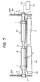
- FIG. 5 shows the charger including the charge roller 20 embodying the present invention in detail.
- the charge roller 20 is made up of a cylindrical or hollow, cylindrical shaft 3 formed of metal or similar conductive material, a hollow, cylindrical elastic member 4 coaxially affixed to the circumference of the shaft 3, and at least two spacers 1 affixed to the circumference of the elastic member 4.
- two spacers 1 are mounted on opposite end portions of the elastic member 4.
- the elastic member 4 is formed of rubber or similar elastic material having a volume resistivity of 1 x 10 3 ⁇ cm to 1 x 10 8 ⁇ cm and is about 1.5 mm thick by way of example.
- the shaft 3 has an outside diameter of, e.g., 9 mm.
- each spacer 1 is made up of a base film formed of PET (polyethylene terephthalate) or similar elastic, insulating resin and an adhesive layer formed on one surface of the base film.
- the base film is wrapped around the elastic member 4 by one turn and affixed thereto via the adhesive layer.
- the spacer 1 is, e.g., 8 mm wide.
- the base film is, e.g., 25 ⁇ m thick while the adhesive layer is , e.g., 35 ⁇ m thick.
- the shaft 3 is rotatably supported by bearings 5 at axially opposite end portions thereof.
- the bearings 5 are received in openings 6 formed in opposite side walls 43A.
- the bearings 5 each are movable toward and away from the image carrier 2 and constantly biased toward the drum 2 by a compression spring 7. In this condition, the spacers 1 are pressed against the drum 2 to thereby form a gap G between the elastic member 4 and the drum 2.
- a power supply 10 applies a voltage to the shaft 3 of the charge roller 20 in order to charge the surface of the drum 2, as described previously.
- the above voltage should preferably be a DC-biased AC voltage, e.g., an AC peak-to-peak voltage of 2 kV biased by a DC voltage of -700 V.
- the drum unit 41 including the charger and drum 2 and the developing unit 42 are independent of each other.
- the two units 41 and 42 may be constructed into a single drum unit, if desired.
- the gap G between the charge roller 20 and the drum 2 is excessively great, the charging of the drum 2 becomes defective and disturbs the toner image formed on the drum 2, as discussed earlier.
- the gap G is maintained at a preselected value, i.e., 50 ⁇ m or below in the configuration shown in FIG. 4. More specifically, when each spacer 1 includes a 35 ⁇ m thick adhesive layer, the adhesive layer and the portion of the elastic member 4 where the spacer 1 is affixed elastically deform when pressed against the drum 2, implementing a gap G of 50 ⁇ m or below.
- the elastic member 4 elastically deforms and allows the carrier grain to pass through the gap G. This protects the surface of the drum 2 from a scratch. Should the surface of the charge roller be formed of a rigid material, the carrier grain would be caught by the gap G and would thereby damage the surface of the drum 2.
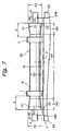
- FIG. 6 shows a specific example of the illustrative embodiment.
- the previously stated rising portion 61 radially protrudes from each end portion E of the elastic member 4 and extends over the entire circumference when the elastic member 4 is ground.
- the rising portion 61 is likely to increase the gap G between the charge roller 20 and the drum 2 above 50 ⁇ m.
- the spacer 1 is positioned at a distance of at least W/9 mm from the end RE of the elastic member 4 toward the center CL. More specifically, the axially outermost edge of the spacer 1 is spaced from the end RE of the elastic member 4 by a distance S of W/9 mm or above toward the center CL.
- the spacer 1 is spaced from the end RE of the elastic member 4 by a distance of 10/9 mm or above in the axial direction of the member 4.
- the maximum outside diameter D3 of the rising portion 61 differs from one charge roller to another charge roller, as stated previously. However, the outside diameter D1 of the rising portion 61 sequentially decreases toward the center CL of the elastic member 4. It follows that the spacer 1 spaced from the end RE of the elastic member, as stated above, prevents the outside diameter of the portion of the elastic member where the spacer 1 is affixed from being noticeably scattered.
- each spacer 1 is positioned in the intermediate portion I of the elastic member 4 where the rising portions 61 are absent.
- the outside diameter of the elastic member 4 is substantially free from scattering.
- the spacers 1 When the spacers 1 are pressed against the drum 2, they successfully maintain the gap G between the portion of the elastic member between the spacers 1 and the drum 2 constant, e.g., 50 ⁇ m or below. This frees the surface of the drum 2 from defective charging and thereby enhances the quality of a toner image formed on the drum 2.
- the drum 2 is made up of a base 63 formed of aluminum or similar conductor and a photoconductive layer 64 coated on the base 63, and that the base 63 is exposed to the outside at axially opposite ends of the drum 2. Then, discharge is apt to occur between the outermost edge 62 of the rising portion 61 and the exposed portion of the base 63. It is therefore preferable to position the end RE of the elastic member 4 and the end 64E of the photoconductive layer 64 at a preselected distance, e.g., 2 mm or above from each other in order to obviate the above discharge.
- each rising portion 61 should preferably have part thereof, which includes the maximum diameter, cut by a grindstone or a cutter, not shown, over the entire circumference.
- FIG. 8 shows a case wherein the rising portion 61 is partly cut to reduce the outside diameter of the portion 61
- FIG. 9 shows a case wherein the entire rising portion 61 is cut for the same purpose.
- dash-and-dots lines each show the original configuration of the rising portion 61.
- each spacer 1 extends over the cut surface 65 of the associated rising portion 61 and part of the elastic member 4 adjoining the cut surface 65.
- each spacer 1 is spaced from the cut surface 65 toward the center of the elastic member 4. This is also successful to prevent the rising portion 61 from increasing the gap G above the preselected value and therefore to free the surface of the drum 1 between the spacers 1 from defective charging.
- the distance L1 between the spacers 1 can therefore be increased, compared to the configuration shown in FIG. 8.
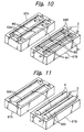
- FIGS. 10 and 11 A specific procedure for producing the charge roller 20 made up of the shaft 3, elastic member 4 and spacers 1 will be described with reference to FIGS. 10 and 11.
- an upper mold 67A and a lower mold 67B having cavities 66A and 66B, respectively, and identical in configuration are prepared.
- identical shafts 3 each are set in a particular cavity 66B of the lower mold 67B.
- FIG. 11 after the two molds 67A and 67B have been put together, the spaces between the cavities 66A and 66B are filled with molten rubber. After the molten rubber has been cooled off, the two molds 67A and 67B are separated from each other. Consequently, an elastic member 4 is formed on each of the shafts 3.
- the shafts 3 with the respective elastic members 4 each are removed from the lower mold 67B. Thereafter, each elastic member 4 is ground in the manner described with reference to FIG. 1.
- the elastic member 4 and grindstone or grinder 60 may be rotated. At this instant, one or both of the elastic member 4 and grindstone 60 may be moved in the directions F1 and F2.
- the spacers 12 are affixed to the ground surface of the elastic member 4.
- the grindstone 60 grinds the surface of the elastic member 4, which is affixed to the shaft 3, with the grindstone 60 and elastic member 4 moving in the directions F1 and F2 relative to each other, as stated above.
- the pressure acting between the grindstone 60 and the elastic member 4 is made higher than when the grindstone 60 grinds the intermediate portion I of the member 4.
- the grindstone 60 therefore cuts the end portion E more than conventional and thereby obviates the rising portion 61 or reduces the outside diameter of the same.
- the relative speed between the grindstone 60 and the elastic member 4 moving relative to each other may be lowered when the grindstone 60 grinds the end portion E than when it grinds the intermediate portion I.
- the grindstone 60 therefore cuts the end portion E more than conventional and thereby obviates the rising portion 61 or reduces the outside diameter thereof.
- FIG. 12 shows in an exaggerated scale a shaft 3 having an outside diameter d1 at its portions to which the end portions E of the elastic member 4 are affixed, and an outside diameter d2 at a portion to which the intermediate portion I of the member 4 is affixed.
- the outside diameter d1 is selected tq be greater than the outside diameter d2.
- the cavities 66A and 66B shown in FIG. 10 each may have a width W1 at each axial end portion and a width W2 at the intermediate portion, if desired.
- the width W1 is selected to be slightly smaller than the width W2.
- the elastic member 4 formed by such molds 67A and 67B has a thickness T1 at opposite end portions E and a thickness T2 at the intermediate portion I that is greater than the thickness T1.
- the elastic member 4 After the elastic member 4 has been affixed to the shaft 3, it is ground in the same manner as described previously. Because the thickness T1 is smaller than the thickness T2, the ground elastic member 4 is free from rising portions or the outside diameter of each rising portion is reduced. This procedure may also be combined with the procedure of FIGS. 10 and 11.
- the procedures described above successfully obviate rising portions or reduce the outside diameter of the same and therefore solve or effectively reduce the problems ascribable to the rising portions.
- the portion of the elastic member 4 between the spacers 1 can be provided with a sufficient length because the spacers 11 are located at the ends of the member or positions adjoining them.
- the present invention is applicable to any other body to be charged, e.g., the charge roller 20 shown in FIG. 4 and configured to charge the paper sheet P carried on the belt 8 for thereby electrostatically retaining the paper sheet P on the belt 8.
- the present invention provides a charge roller having various unprecedented advantages, as enumerated below.
- the elastic member of the charge roller is preferably ground such that the diameter of the elastic member is constant or decreases slightly to the end of the member.
- the spacers are preferably located adjacent to the rising portion (maximum diameter portion) or spaced from the rising portions (maximum diameter portions).
- the rising portions (maximum diameter portions) are in particular located at the outside ends of the elastic member.
- the diameter of the rising portions is higher than the average diameter of the elastic member.
- the outside ends of the elastic member have a diameter smaller than the average diameter of the elastic member.
- the elastic member is preferably ground such that the diameter of the rising portions is reduced.
- the reduction is such that the diameter of the rising portions is at least smaller as in the remaining portions of the elastic member or even smaller than the diameter in the remaining portion of the elastic member or smaller than the average diameter of the elastic member.
Landscapes
- Physics & Mathematics (AREA)
- Engineering & Computer Science (AREA)
- Plasma & Fusion (AREA)
- General Physics & Mathematics (AREA)
- Electrostatic Charge, Transfer And Separation In Electrography (AREA)
- Rolls And Other Rotary Bodies (AREA)
- Electrophotography Configuration And Component (AREA)
Abstract
Description
Claims (15)
- A charge roller comprising:wherein assuming that rising portions formed, when a circumference of said elastic member is ground during production, at axially opposite end portions of said elastic member each have a width of W mm in an axial direction, said plurality of spacers each are positioned at a distance of at least W/9 mm from an end of said elastic member toward a center of said elastic member in the axial direction.a shaft;an elastic member affixed to a circumference of said shaft; anda plurality or number of spacers affixed to said elastic member;
- A charge roller comprising:wherein assuming that rising portions formed, when a circumference of said elastic member is ground during production, at axially opposite end portions of said elastic member each have at least part thereof including a maximum diameter cut.a shaft;an elastic member affixed to a circumference of said shaft; anda plurality or number of spacers affixed to said elastic member;
- A charge roller comprising:wherein rising portions formed, when a circumference of said elastic member is ground during production, at axially opposite end portions of said elastic member each have at least part thereof including a maximum diameter cut, anda shaft;an elastic member affixed to a circumference of said shaft; anda plurality or number of spacers affixed to said elastic member;
said plurality of spacers each extend over a cut surface of one of the rising portions and part of said elastic member closer to a center of said elastic member in an axial direction than said cut surface. - A charge roller comprising:wherein rising portions formed, when a circumference of said elastic member is ground during production, at axially opposite end portions of said elastic member each have at least part thereof including a maximum diameter cut, anda shaft;an elastic member affixed to a circumference of said shaft; anda plurality or numbers of spacers affixed to said elastic member;
said plurality of spacers each are positioned in particular part of said elastic member closer to a center of said elastic member in an axial direction than a cut surface of one of said rising portion. - A charge roller comprising:wherein the elastic member comprises maximum portions which have a diameter grater than the diameter of adjacent or other portions of the elastic member; anda shaft;an elastic member affixed to a circumference of said shaft; anda number of spacers affixed to said elastic member;
wherein at least one of the number of spacers is arranged such that it does not cover one of the maximum portions or is arranged to be distant from the maximum portions. - A charge roller, in particular according to one of the proceedings claims, comprising:wherein the elastic member comprises a decreasing portion in which the diameter of the elastic member decreases towards the outside, preferably, the decreasing portion is arranged at an end of the elastic member.a shaft;an elastic member affixed to a circumference of the shaft; anda number of spacers affixed to the elastic member;
- A charger comprising a charge roller according to any of claims 1 to 6, said plurality of spacers are pressed against a body to be charged such that part of said elastic member between said spacers and a surface of said body face each other via a gap, said charge roller charging said surface of said body with a voltage applied thereto.
- An image carrier unit comprising a charger according to claim 7 or a charge roller according to any of claims 1 to 6, and an image carrier to be charged by said charger or charge roller, respectively.
- An image forming apparatus comprising a charger according to claim 7, a charge roller according to any of claims 1 to 6, or an image carrier unit according to claim 8.
- A method of producing a charge roller comprising a shaft, an elastic member affixed to a circumference of said shaft, and a plurality or number of spacers mounted on said elastic member, said method comprising the steps of grinding the elastic member for achieving a constant outside diameter of the elastic member, wherein the constant diameter is achieved by appropriately configuring the elastic member and/or the shaft in a shape which deviates in diameter from an average diameter at the outside ends thereof and/or by performing the grinding such that the higher tendency of the outside portions of the elastic member in comparison to the inside portions to recede from a grinder is compensated in order to achieve the constant diameter of the elastic member.
- A method of producing a charge roller comprising a shaft, an elastic member affixed to a circumference of said shaft, and a plurality of spacers mounted on said elastic member, said method in particular according to claim 10, comprising the steps of:affixing the elastic member to the shaft;causing at least one of the elastic member and a grinder pressed against said elastic member to rotate;causing the elastic member and the grinder to move relative to each other in an axial direction of said elastic member to thereby grind a circumference of said elastic member; andcausing a higher pressure to act between the grinder and the elastic member when said grinder grinds opposite end portions of said elastic member in an axial direction than when said grinder grinds an intermediate portion between said end portions.
- A method of producing a charge roller comprising a shaft, an elastic member affixed to a circumference of said shaft, and a plurality of spacers mounted on said elastic member, said method in particular according to claim 10, comprising the steps of:affixing the elastic member to the shaft;causing at least one of the elastic member and a grinder pressed against said elastic member to rotate;causing the elastic member and the grinder to move relative to each other in an axial direction of said elastic member to thereby grind a circumference of said elastic member; andmaking a relative speed between the grinder and the elastic member lower when said grinder grinds opposite end portions of said elastic member in an axial direction than when said grinder grinds an intermediate portion between said end portions.
- A method of producing a charge roller comprising a shaft, an elastic member affixed to a circumference of said shaft, and a plurality of spacers mounted on said elastic member, said method in particular according to claim 10, comprising the steps of:configuring the shaft such that said shaft has a greater outside diameter at portions thereof to which axially opposite end portions of the elastic member are affixed than at a portion to which an intermediate portion of said elastic member is affixed;affixing the elastic member to the shaft;causing at least one of the elastic member and a grinder pressed against said elastic member to rotate; andcausing the elastic member and the grinder to move relative to each other in an axial direction of said elastic member to thereby grind a circumference of said elastic member.
- A method of producing a charge roller comprising a shaft, an elastic member affixed to a circumference of said shaft, and a plurality of spacers mounted on said elastic member, said method in particular according to claim 10, comprising the steps of:configuring the shaft or elastic member such that said shaft or elastic member has a smaller thickness at axially opposite end portions thereof than at an intermediate portion between said end portions;affixing the elastic member to a circumference of the shaft;causing at least one of the elastic member and a grinder pressed against said elastic member to rotate; andcausing the elastic member and the grinder to move relative to each other in an axial direction of said elastic member to thereby grind a circumference of said elastic member.
- A charge roller comprising a shaft, an elastic member affixed to a circumference of said shaft and a plurality of spacers mounted on said elastic member, said charge roller being produced in accordance with the method of any of claims 10 to 14.
Applications Claiming Priority (2)
| Application Number | Priority Date | Filing Date | Title |
|---|---|---|---|
| JP2000291330A JP3719647B2 (en) | 2000-09-25 | 2000-09-25 | Charging roller, charging device, carrier unit, image forming apparatus, and manufacturing method of charging roller |
| JP2000291330 | 2000-09-25 |
Publications (3)
| Publication Number | Publication Date |
|---|---|
| EP1191403A2 true EP1191403A2 (en) | 2002-03-27 |
| EP1191403A3 EP1191403A3 (en) | 2003-04-02 |
| EP1191403B1 EP1191403B1 (en) | 2006-10-18 |
Family
ID=18774415
Family Applications (1)
| Application Number | Title | Priority Date | Filing Date |
|---|---|---|---|
| EP01122561A Expired - Lifetime EP1191403B1 (en) | 2000-09-25 | 2001-09-25 | Charge roller for an image forming apparatus |
Country Status (4)
| Country | Link |
|---|---|
| US (1) | US6628912B2 (en) |
| EP (1) | EP1191403B1 (en) |
| JP (1) | JP3719647B2 (en) |
| DE (1) | DE60123901T2 (en) |
Cited By (3)
| Publication number | Priority date | Publication date | Assignee | Title |
|---|---|---|---|---|
| US7050742B2 (en) * | 2003-10-31 | 2006-05-23 | Hewlett-Packard Development Company, L.P. | Hard imaging apparatus charging devices and hard imaging device charging methods |
| CN100445885C (en) * | 2003-03-11 | 2008-12-24 | 夏普株式会社 | image forming device |
| US8038590B2 (en) | 2005-05-27 | 2011-10-18 | Ricoh Company, Ltd. | Conductive member, process cartridge having the same, and image forming apparatus having the process cartridge |
Families Citing this family (21)
| Publication number | Priority date | Publication date | Assignee | Title |
|---|---|---|---|---|
| JP2004062062A (en) * | 2002-07-31 | 2004-02-26 | Ricoh Co Ltd | Charging device and image forming device |
| JP2005070750A (en) * | 2003-08-07 | 2005-03-17 | Ricoh Co Ltd | Cleaning member, cleaning device, charging device, transfer device, process cartridge, and image forming apparatus |
| JP4418192B2 (en) * | 2003-08-20 | 2010-02-17 | 株式会社リコー | Cleaning device, process cartridge, and image forming apparatus |
| JP2005070274A (en) * | 2003-08-22 | 2005-03-17 | Ricoh Co Ltd | Image forming apparatus, process cartridge, toner |
| JP4302471B2 (en) * | 2003-09-18 | 2009-07-29 | 株式会社リコー | Conductive member, process cartridge including the conductive member, and image forming apparatus |
| US20050089346A1 (en) * | 2003-10-28 | 2005-04-28 | Xerox Corporation | Spaced biased roll charging member having clipped AC input voltage |
| US7477862B2 (en) * | 2004-02-09 | 2009-01-13 | Ricoh Company, Ltd. | Charged device, cleaning device, process cartridge, toner, and image-forming device that uses these |
| JP2005300626A (en) * | 2004-04-07 | 2005-10-27 | Ricoh Co Ltd | Cleaning device, image forming device |
| JP2006168955A (en) * | 2004-12-17 | 2006-06-29 | Oki Data Corp | Medium discharge mechanism and image forming apparatus |
| US7215908B2 (en) * | 2005-03-30 | 2007-05-08 | Xerox Corporation | Non-contact bias charge roll biased with burst modulation waveform |
| US7505715B2 (en) * | 2005-08-01 | 2009-03-17 | Seiko Epson Corporation | Charging roller and image forming apparatus with the same |
| JP2008116752A (en) * | 2006-11-06 | 2008-05-22 | Ricoh Co Ltd | Image forming apparatus |
| JP4934512B2 (en) | 2007-06-08 | 2012-05-16 | 株式会社リコー | Image forming apparatus and process cartridge |
| JP2009003029A (en) * | 2007-06-19 | 2009-01-08 | Seiko Epson Corp | Rolling apparatus, developing roller manufacturing method, developing roller, developing apparatus, and image forming apparatus |
| US20110293330A1 (en) * | 2010-06-01 | 2011-12-01 | Toshiba Tec Kabushiki Kaisha | Image forming apparatus and gap maintaining method of charging roller |
| US8805245B2 (en) * | 2010-12-16 | 2014-08-12 | Samsung Electronics Co., Ltd. | Charging device and image forming apparatus using the same |
| JP5695407B2 (en) * | 2010-12-16 | 2015-04-08 | 三星電子株式会社Samsung Electronics Co.,Ltd. | Charging device and image forming apparatus |
| JP5569414B2 (en) * | 2011-01-28 | 2014-08-13 | ブラザー工業株式会社 | Image forming apparatus |
| US20170176883A1 (en) * | 2014-08-18 | 2017-06-22 | Hewlett-Packard Development Company, L.P. | Printing using a metal-surface charging element |
| JP5983799B2 (en) * | 2015-02-12 | 2016-09-06 | 富士ゼロックス株式会社 | Rubber roll end part processing apparatus and rubber roll manufacturing method |
| KR102454766B1 (en) * | 2017-10-25 | 2022-10-13 | 엘지전자 주식회사 | Roll to roll cleaning apparatus |
Family Cites Families (26)
| Publication number | Priority date | Publication date | Assignee | Title |
|---|---|---|---|---|
| JPS63208877A (en) * | 1987-02-26 | 1988-08-30 | Canon Inc | contact charging device |
| JPH02103582A (en) | 1988-10-13 | 1990-04-16 | Fuji Xerox Co Ltd | Manufacture of pressure roller for fixing device |
| JPH03240076A (en) | 1990-02-17 | 1991-10-25 | Canon Inc | charging device |
| JP2949785B2 (en) | 1990-06-07 | 1999-09-20 | キヤノン株式会社 | Charging device |
| JPH04360167A (en) | 1991-06-06 | 1992-12-14 | Mitsubishi Kasei Corp | Proximity electrifier |
| US5424814A (en) | 1992-01-11 | 1995-06-13 | Ricoh Company, Ltd. | Developing device with microfields formed on developer carrier |
| US5339141A (en) | 1992-02-16 | 1994-08-16 | Ricoh Company, Ltd. | Developing device with a developer carrier capable of forming numerous microfields thereon |
| JPH06110261A (en) | 1992-09-25 | 1994-04-22 | Ricoh Co Ltd | Color image forming device |
| JP3364503B2 (en) | 1992-11-30 | 2003-01-08 | 株式会社リコー | Color image forming equipment |
| US6096395A (en) * | 1992-12-16 | 2000-08-01 | Tokai Rubber Industries, Ltd. | Roll including foam body and method of producing the roll |
| JPH06295127A (en) | 1993-04-08 | 1994-10-21 | Ricoh Co Ltd | Rotary type developing device |
| JP3167219B2 (en) | 1993-04-15 | 2001-05-21 | 株式会社リコー | Rotary developing device |
| JPH06332285A (en) | 1993-05-25 | 1994-12-02 | Ricoh Co Ltd | Rotary developing device |
| US5512984A (en) | 1993-08-09 | 1996-04-30 | Ricoh Company, Ltd. | Revolver type developing device for an image forming apparatus |
| DE69534979T2 (en) | 1994-03-16 | 2006-10-26 | Canon K.K. | Charging element and charging device |
| JP3336808B2 (en) | 1994-04-11 | 2002-10-21 | 株式会社リコー | Rotary developing device |
| JPH08146765A (en) | 1994-09-20 | 1996-06-07 | Ricoh Co Ltd | Development device |
| JPH0973211A (en) * | 1995-09-05 | 1997-03-18 | Canon Inc | Charging member, process cartridge, and image forming apparatus |
| JPH09244359A (en) | 1996-03-11 | 1997-09-19 | Ricoh Co Ltd | Image forming device |
| JPH10123800A (en) | 1996-10-19 | 1998-05-15 | Ricoh Co Ltd | Image forming device |
| JPH10293446A (en) | 1997-04-19 | 1998-11-04 | Ricoh Co Ltd | Electrostatic image developing device |
| JP3515890B2 (en) | 1997-11-26 | 2004-04-05 | 株式会社リコー | Charging device for image forming apparatus |
| JP2000010454A (en) | 1998-06-19 | 2000-01-14 | Ricoh Co Ltd | Image forming device |
| US6381432B1 (en) * | 1998-12-16 | 2002-04-30 | Brother Kogyo Kabushiki Kaisha | Charging device having a toner remover |
| JP4409649B2 (en) | 1999-01-27 | 2010-02-03 | 住友ゴム工業株式会社 | Conductive elastic roller |
| JP3795709B2 (en) | 1999-07-19 | 2006-07-12 | 株式会社リコー | Image forming apparatus |
-
2000
- 2000-09-25 JP JP2000291330A patent/JP3719647B2/en not_active Expired - Fee Related
-
2001
- 2001-09-24 US US09/960,354 patent/US6628912B2/en not_active Expired - Fee Related
- 2001-09-25 EP EP01122561A patent/EP1191403B1/en not_active Expired - Lifetime
- 2001-09-25 DE DE60123901T patent/DE60123901T2/en not_active Expired - Lifetime
Cited By (3)
| Publication number | Priority date | Publication date | Assignee | Title |
|---|---|---|---|---|
| CN100445885C (en) * | 2003-03-11 | 2008-12-24 | 夏普株式会社 | image forming device |
| US7050742B2 (en) * | 2003-10-31 | 2006-05-23 | Hewlett-Packard Development Company, L.P. | Hard imaging apparatus charging devices and hard imaging device charging methods |
| US8038590B2 (en) | 2005-05-27 | 2011-10-18 | Ricoh Company, Ltd. | Conductive member, process cartridge having the same, and image forming apparatus having the process cartridge |
Also Published As
| Publication number | Publication date |
|---|---|
| EP1191403B1 (en) | 2006-10-18 |
| JP3719647B2 (en) | 2005-11-24 |
| JP2002099135A (en) | 2002-04-05 |
| DE60123901T2 (en) | 2007-06-14 |
| US6628912B2 (en) | 2003-09-30 |
| US20020037180A1 (en) | 2002-03-28 |
| DE60123901D1 (en) | 2006-11-30 |
| EP1191403A3 (en) | 2003-04-02 |
Similar Documents
| Publication | Publication Date | Title |
|---|---|---|
| EP1191403B1 (en) | Charge roller for an image forming apparatus | |
| US5153654A (en) | Image forming apparatus having transfer member for carrying transfer material | |
| US5311264A (en) | Developing apparatus for developing electrostatic latent image using one component developer | |
| EP0921445B1 (en) | Developing apparatus using one-component toner | |
| EP1865387B1 (en) | Charging roller cleaning device and image forming apparatus including the same | |
| US5867755A (en) | Electrophotographic type image forming device and developing roller for use in the device | |
| US6035163A (en) | Vibration absorbing bias charge roll | |
| US7565098B2 (en) | Developing device, process cartridge and image forming apparatus | |
| US20060034639A1 (en) | Apparatus for forming image using liquid development | |
| CN103092034A (en) | Developing device and image forming apparatus using the same | |
| US7330684B2 (en) | Developing device, image forming apparatus, image forming system, charging member, and method for manufacturing developing device | |
| US8036585B2 (en) | Lubricant supplying unit, process unit incorporating same, image forming apparatus incorporating same, and method of manufacturing same | |
| EP0636950B1 (en) | Developing apparatus having rotatable developer supply member for developer carrying member | |
| US20060285871A1 (en) | Image-forming device | |
| US6324366B1 (en) | Sleeve rotation-feed apparatus, developing apparatus, image formation apparatus, and fixation apparatus | |
| JPH0651618A (en) | Developing device | |
| JP3566506B2 (en) | Toner transport roller | |
| JP2004021043A (en) | Developer carrier, developing device, image forming device, and process cartridge | |
| JPH07333996A (en) | Image forming device | |
| JP3984326B2 (en) | Developing device and process cartridge equipped with the same | |
| JP2003316119A (en) | Charging member, charging device, image forming unit and image forming apparatus using the same | |
| CN100424590C (en) | Developing device and manufacturing method, image forming apparatus, image forming system, and charging member | |
| JPS61238072A (en) | Developing device | |
| KR100477664B1 (en) | Liquid image developing apparatus | |
| JPH056097A (en) | Development device |
Legal Events
| Date | Code | Title | Description |
|---|---|---|---|
| PUAI | Public reference made under article 153(3) epc to a published international application that has entered the european phase |
Free format text: ORIGINAL CODE: 0009012 |
|
| AK | Designated contracting states |
Kind code of ref document: A2 Designated state(s): AT BE CH CY DE DK ES FI FR GB GR IE IT LI LU MC NL PT SE TR |
|
| AX | Request for extension of the european patent |
Free format text: AL;LT;LV;MK;RO;SI |
|
| PUAL | Search report despatched |
Free format text: ORIGINAL CODE: 0009013 |
|
| AK | Designated contracting states |
Kind code of ref document: A3 Designated state(s): AT BE CH CY DE DK ES FI FR GB GR IE IT LI LU MC NL PT SE TR |
|
| AX | Request for extension of the european patent |
Extension state: AL LT LV MK RO SI |
|
| 17P | Request for examination filed |
Effective date: 20030526 |
|
| AKX | Designation fees paid |
Designated state(s): DE FR GB |
|
| 17Q | First examination report despatched |
Effective date: 20040625 |
|
| GRAP | Despatch of communication of intention to grant a patent |
Free format text: ORIGINAL CODE: EPIDOSNIGR1 |
|
| RIC1 | Information provided on ipc code assigned before grant |
Ipc: G03G 15/02 20060101AFI20060314BHEP |
|
| RTI1 | Title (correction) |
Free format text: CHARGE ROLLER FOR AN IMAGE FORMING APPARATUS |
|
| GRAS | Grant fee paid |
Free format text: ORIGINAL CODE: EPIDOSNIGR3 |
|
| GRAA | (expected) grant |
Free format text: ORIGINAL CODE: 0009210 |
|
| AK | Designated contracting states |
Kind code of ref document: B1 Designated state(s): DE FR GB |
|
| REG | Reference to a national code |
Ref country code: GB Ref legal event code: FG4D |
|
| REF | Corresponds to: |
Ref document number: 60123901 Country of ref document: DE Date of ref document: 20061130 Kind code of ref document: P |
|
| ET | Fr: translation filed | ||
| PLBE | No opposition filed within time limit |
Free format text: ORIGINAL CODE: 0009261 |
|
| STAA | Information on the status of an ep patent application or granted ep patent |
Free format text: STATUS: NO OPPOSITION FILED WITHIN TIME LIMIT |
|
| 26N | No opposition filed |
Effective date: 20070719 |
|
| REG | Reference to a national code |
Ref country code: FR Ref legal event code: PLFP Year of fee payment: 16 |
|
| REG | Reference to a national code |
Ref country code: FR Ref legal event code: PLFP Year of fee payment: 17 |
|
| PGFP | Annual fee paid to national office [announced via postgrant information from national office to epo] |
Ref country code: GB Payment date: 20170921 Year of fee payment: 17 Ref country code: DE Payment date: 20170928 Year of fee payment: 17 Ref country code: FR Payment date: 20170928 Year of fee payment: 17 |
|
| REG | Reference to a national code |
Ref country code: DE Ref legal event code: R119 Ref document number: 60123901 Country of ref document: DE |
|
| GBPC | Gb: european patent ceased through non-payment of renewal fee |
Effective date: 20180925 |
|
| PG25 | Lapsed in a contracting state [announced via postgrant information from national office to epo] |
Ref country code: DE Free format text: LAPSE BECAUSE OF NON-PAYMENT OF DUE FEES Effective date: 20190402 |
|
| PG25 | Lapsed in a contracting state [announced via postgrant information from national office to epo] |
Ref country code: FR Free format text: LAPSE BECAUSE OF NON-PAYMENT OF DUE FEES Effective date: 20180930 |
|
| PG25 | Lapsed in a contracting state [announced via postgrant information from national office to epo] |
Ref country code: GB Free format text: LAPSE BECAUSE OF NON-PAYMENT OF DUE FEES Effective date: 20180925 |