EP1191369A2 - Optical fiber, and dispersion compensator using same, optical transmission line using same and optical transmission system using same - Google Patents
Optical fiber, and dispersion compensator using same, optical transmission line using same and optical transmission system using same Download PDFInfo
- Publication number
- EP1191369A2 EP1191369A2 EP01307929A EP01307929A EP1191369A2 EP 1191369 A2 EP1191369 A2 EP 1191369A2 EP 01307929 A EP01307929 A EP 01307929A EP 01307929 A EP01307929 A EP 01307929A EP 1191369 A2 EP1191369 A2 EP 1191369A2
- Authority
- EP
- European Patent Office
- Prior art keywords
- optical transmission
- wavelength band
- transmission line
- dispersion
- optical fiber
- Prior art date
- Legal status (The legal status is an assumption and is not a legal conclusion. Google has not performed a legal analysis and makes no representation as to the accuracy of the status listed.)
- Withdrawn
Links
Images

Classifications
-
- G—PHYSICS
- G02—OPTICS
- G02B—OPTICAL ELEMENTS, SYSTEMS OR APPARATUS
- G02B6/00—Light guides; Structural details of arrangements comprising light guides and other optical elements, e.g. couplings
- G02B6/02—Optical fibres with cladding with or without a coating
- G02B6/036—Optical fibres with cladding with or without a coating core or cladding comprising multiple layers
- G02B6/03616—Optical fibres characterised both by the number of different refractive index layers around the central core segment, i.e. around the innermost high index core layer, and their relative refractive index difference
- G02B6/03638—Optical fibres characterised both by the number of different refractive index layers around the central core segment, i.e. around the innermost high index core layer, and their relative refractive index difference having 3 layers only
- G02B6/03644—Optical fibres characterised both by the number of different refractive index layers around the central core segment, i.e. around the innermost high index core layer, and their relative refractive index difference having 3 layers only arranged - + -
-
- G—PHYSICS
- G02—OPTICS
- G02B—OPTICAL ELEMENTS, SYSTEMS OR APPARATUS
- G02B6/00—Light guides; Structural details of arrangements comprising light guides and other optical elements, e.g. couplings
-
- G—PHYSICS
- G02—OPTICS
- G02B—OPTICAL ELEMENTS, SYSTEMS OR APPARATUS
- G02B6/00—Light guides; Structural details of arrangements comprising light guides and other optical elements, e.g. couplings
- G02B6/02—Optical fibres with cladding with or without a coating
- G02B6/02214—Optical fibres with cladding with or without a coating tailored to obtain the desired dispersion, e.g. dispersion shifted, dispersion flattened
- G02B6/02219—Characterised by the wavelength dispersion properties in the silica low loss window around 1550 nm, i.e. S, C, L and U bands from 1460-1675 nm
- G02B6/02228—Dispersion flattened fibres, i.e. having a low dispersion variation over an extended wavelength range
-
- G—PHYSICS
- G02—OPTICS
- G02B—OPTICAL ELEMENTS, SYSTEMS OR APPARATUS
- G02B6/00—Light guides; Structural details of arrangements comprising light guides and other optical elements, e.g. couplings
- G02B6/02—Optical fibres with cladding with or without a coating
- G02B6/02214—Optical fibres with cladding with or without a coating tailored to obtain the desired dispersion, e.g. dispersion shifted, dispersion flattened
- G02B6/02219—Characterised by the wavelength dispersion properties in the silica low loss window around 1550 nm, i.e. S, C, L and U bands from 1460-1675 nm
- G02B6/02228—Dispersion flattened fibres, i.e. having a low dispersion variation over an extended wavelength range
- G02B6/02238—Low dispersion slope fibres
- G02B6/02242—Low dispersion slope fibres having a dispersion slope <0.06 ps/km/nm2
-
- G—PHYSICS
- G02—OPTICS
- G02B—OPTICAL ELEMENTS, SYSTEMS OR APPARATUS
- G02B6/00—Light guides; Structural details of arrangements comprising light guides and other optical elements, e.g. couplings
- G02B6/02—Optical fibres with cladding with or without a coating
- G02B6/02214—Optical fibres with cladding with or without a coating tailored to obtain the desired dispersion, e.g. dispersion shifted, dispersion flattened
- G02B6/02219—Characterised by the wavelength dispersion properties in the silica low loss window around 1550 nm, i.e. S, C, L and U bands from 1460-1675 nm
- G02B6/02252—Negative dispersion fibres at 1550 nm
- G02B6/02257—Non-zero dispersion shifted fibres, i.e. having a small negative dispersion at 1550 nm, e.g. ITU-T G.655 dispersion between - 1.0 to - 10 ps/nm.km for avoiding nonlinear effects
-
- G—PHYSICS
- G02—OPTICS
- G02B—OPTICAL ELEMENTS, SYSTEMS OR APPARATUS
- G02B6/00—Light guides; Structural details of arrangements comprising light guides and other optical elements, e.g. couplings
- G02B6/02—Optical fibres with cladding with or without a coating
- G02B6/02214—Optical fibres with cladding with or without a coating tailored to obtain the desired dispersion, e.g. dispersion shifted, dispersion flattened
- G02B6/02219—Characterised by the wavelength dispersion properties in the silica low loss window around 1550 nm, i.e. S, C, L and U bands from 1460-1675 nm
- G02B6/02252—Negative dispersion fibres at 1550 nm
- G02B6/02261—Dispersion compensating fibres, i.e. for compensating positive dispersion of other fibres
-
- G—PHYSICS
- G02—OPTICS
- G02B—OPTICAL ELEMENTS, SYSTEMS OR APPARATUS
- G02B6/00—Light guides; Structural details of arrangements comprising light guides and other optical elements, e.g. couplings
- G02B6/24—Coupling light guides
- G02B6/26—Optical coupling means
- G02B6/28—Optical coupling means having data bus means, i.e. plural waveguides interconnected and providing an inherently bidirectional system by mixing and splitting signals
- G02B6/293—Optical coupling means having data bus means, i.e. plural waveguides interconnected and providing an inherently bidirectional system by mixing and splitting signals with wavelength selective means
- G02B6/29371—Optical coupling means having data bus means, i.e. plural waveguides interconnected and providing an inherently bidirectional system by mixing and splitting signals with wavelength selective means operating principle based on material dispersion
- G02B6/29374—Optical coupling means having data bus means, i.e. plural waveguides interconnected and providing an inherently bidirectional system by mixing and splitting signals with wavelength selective means operating principle based on material dispersion in an optical light guide
- G02B6/29376—Optical coupling means having data bus means, i.e. plural waveguides interconnected and providing an inherently bidirectional system by mixing and splitting signals with wavelength selective means operating principle based on material dispersion in an optical light guide coupling light guides for controlling wavelength dispersion, e.g. by concatenation of two light guides having different dispersion properties
- G02B6/29377—Optical coupling means having data bus means, i.e. plural waveguides interconnected and providing an inherently bidirectional system by mixing and splitting signals with wavelength selective means operating principle based on material dispersion in an optical light guide coupling light guides for controlling wavelength dispersion, e.g. by concatenation of two light guides having different dispersion properties controlling dispersion around 1550 nm, i.e. S, C, L and U bands from 1460-1675 nm
Definitions
- the present invention relates to an optical fiber and a dispersion compensator, an optical transmission line and an optical transmission system all of which use this optical fiber and which are applied to e.g., a wavelength division multiplexing (WDM) transmission as one use.
- WDM wavelength division multiplexing
- the WDM transmission is a communication system for transmitting signals of plural wavelengths by one optical fiber.
- an erbium doped fiber amplifier (EDFA) using an erbium doped optical fiber is used as an amplifier of an optical signal.
- This EDFA can directly amplify the optical signal of each wavelength in a wavelength band of 1.5 ⁇ m without converting the optical signal to an electric signal in a repeater using the WDM transmission. Therefore, the WDM of optical communication is accelerated by an appearance of the EDFA.
- the present invention provides an optical fiber suitable for the WDM transmission as one use example, and a dispersion compensator, an optical transmission line and an optical transmission system all of which use this optical fiber.
- This optical fiber comprises a refractive index profile structure constructed by at least three core layers and a clad outside these core layers;
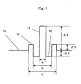
- Fig. 1 is a view showing a refractive index profile structure of an optical fiber in one embodiment of the invention.
- Fig. 2 is an explanatory view showing one example in which a dispersion compensator of one embodiment of the invention is applied to an optical transmission system.
- Fig. 3 is an explanatory view showing one example of the optical transmission system into which an optical transmission line of one embodiment of the invention is incorporated.
- An optical fiber for WDM transmission for reducing non-linearity and providing a small dispersion in a transmission range of an optical signal is proposed as mentioned above. It seemed that the problems of the dispersion and the non-linearity were solved by using the proposed optical fiber of this kind. However, when it is intended that the number of optical signals of the WDM transmission is increased by a request of high capacity transmission, it is necessary to maintain a small dispersion at an entire wavelength interval of a wide range.
- the present invention provides an optical fiber for compensating the dispersion slope of an optical transmission line constructed by an optical fiber providing a small dispersion in the transmission range of an optical signal, and enabling wide range WDM transmission. Further, the invention also provides a dispersion compensator, an optical transmission line and an optical transmission system all of which use this optical fiber.
- a cable cutoff wavelength lies on a short wavelength side from a wavelength of 1520 nm as a lower limit of a using wavelength area (here a wavelength band of 1.5 ⁇ m). Accordingly, a single mode operation is performed in the entire using wavelength area. Therefore, it is possible to obtain stable transmission characteristics having no influence of a disturbance.
- a dispersion value of the optical fiber used in the existing WDM transmission line approximately ranges from 2 to 6 ps/nm/km, and an average dispersion slope is about +0.07 ps/nm 2 /km.
- An optical transmission line for compensating the very small dispersion and reducing the dispersion slope and having flat dispersion characteristics in a wide range of wavelength is realized by connecting the optical fiber of one constructional example of the invention having a negative chromatic dispersion and a negative dispersion slope, to this WDM transmission line having a positive very small dispersion and a positive dispersion slope.
- a usable wavelength range is widened and the WDM transmission can be performed in a wide range of wavelength. Since the dispersion of the WDM transmission line is not zero but is of a very small value to such an extent that no four-wave mixing is caused, a non-linear phenomenon is also restrained.
- a wavelength band of 1.5 ⁇ m shows a wavelength range from 1520 to 1620 nm unless otherwise specified hereinafter.
- a specific wavelength in a 1.5 ⁇ m wavelength band shows a concrete wavelength within the wavelength band of 1.5 ⁇ m such as 1550 nm in wavelength.
- a specific set wavelength band of the wavelength band of 1.5 ⁇ m is an optical transmission wavelength band set within the above wavelength range from 1520 to 1620 nm, and concretely shows a wavelength band at a partial interval within the wavelength band of 1.5 ⁇ m such as a wavelength from 1530 to 1570 nm, etc.
- Fig. 1 shows a refractive index profile structure of an optical fiber in one embodiment of the invention.
- a core is constructed by a three-layer structure.
- the refractive index profile structure shown in Fig. 1 is constructed by sequentially arranging a first core 11, a second core 12, a third core 13, and a clad 14 from the inside to the outside.
- the first core 11 has a maximum refractive index.
- the first core 11 has a relative refractive index difference ⁇ 1 with respect to the clad 14.
- the second core 12 has a relative refractive index difference ⁇ 2 with respect to the clad 14.
- the third core 13 has a relative refractive index difference ⁇ 3 with respect to the clad 14.
- Fig. 2 is an explanatory view showing one example of the case in which a dispersion compensator 24 of one embodiment of the invention is applied to an optical transmission system.
- reference numerals 21, 22, 23, and 25 respectively designate an optical transmitter, an optical amplifier, an existing optical transmission line (WDM transmission line) using an optical fiber for the WDM transmission, and an optical receiver.
- the optical fiber of the invention functions as a fiber for compensating the dispersion and the dispersion slope.
- the external appearance construction of a system of Fig. 2 itself is equal to that of the conventional optical transmission system, but the system of Fig. 2 differs from the conventional system in that the optical fiber of the invention is used in the dispersion compensator 24. Dispersion characteristics are greatly improved by using the optical fiber of the invention in the dispersion compensator 24.
- Fig. 3 shows an optical transmission system constructed by assembling an optical transmission line of one embodiment of the invention.
- reference numerals 31, 32, 33, 34, and 35 respectively designate an optical transmitter, an optical amplifier, a first optical transmission line (here a WDM transmission line) using an existing optical fiber for WDM transmission, a second optical transmission line using the optical fiber of the invention, and an optical receiver.
- An external appearance construction of the system of Fig. 3 itself is equal to that of the conventional system, but the system of Fig. 3 differs from the conventional system in that the optical fiber of the invention is used in the second optical transmission line 34. Dispersion characteristics are greatly improved by using the optical fiber of the invention in the second optical transmission line 34 in comparison with the optical transmission system of the conventional example.
- optical fiber of the invention One embodiment of the optical fiber of the invention will next be explained more specifically.
- the optical fiber of one embodiment of the invention has the refractive index profile structure shown in Fig. 1.
- Optical fibers having this refractive index profile structure are fabricated as samples by changing various kinds of parameters.
- Table 1 shows the parameters of a refractive index profile of each fabricated optical fiber and characteristics at a wavelength of 1550 nm.
- DPS shows a value obtained by dividing a dispersion by a dispersion slope.
- the value of DPS is an index showing the height of a dispersion compensating rate with respect to a positive dispersion optical fiber, and aims at a positive value not more than 200 in this embodiment.
- a column having no numeric value of the DPS shows that there is no meaning of a calculation of the numeric value since both the dispersion and the dispersion slope are not negative.
- the value of DPS can not be set to not less than 200 in a negative dispersion area.
- the fabricated optical fiber No. 1 when ⁇ 1 is not larger than 0.7 %, it should be understood that the optical fiber has no propagation solution in the negative dispersion slope. Therefore, it is said that it is suitable to set ⁇ 1 to not less than 0.8 % and not more than 3.0 %.
- the optical fiber has no propagation solution unless the cutoff wavelength is set on a long wavelength side from 1.5 ⁇ m when ⁇ 2 is too low.
- the cutoff wavelength is set on the long wavelength side from 1520 nm.
- the cutoff wavelength can be set on a short wavelength side from 1520 nm by setting a condition.
- ⁇ 2 is too high as in the fabricated optical fiber No. 7
- no optical fiber having both a negative dispersion and a negative dispersion slope is obtained under a condition in which the cutoff wavelength is not more than 1520 nm.
- the cable cutoff wavelength is set on a long wavelength side from 1520 nm. Accordingly, it is said that it is suitable to set ⁇ 3 to not less than 0.2 % and not more than 0.5 %.
- an outside diameter of the first core is set to a
- an outside diameter of the second core is set to b
- an outside diameter of the third core is set to c
- the ratio a/b is small as in the fabricated optical fiber No. 12
- the dispersion slope becomes steep, but the optical fiber has no propagation solution. It is sufficient to increase the core diameter to have the propagation solution by reducing the ratio a/b, but no negative dispersion is obtained in this case.
- the ratio c/b is not more than 1.1 as in the fabricated optical fiber No. 17, no propagation solution is obtained in the negative dispersion slope.
- the ratio c/b is not less than 2.1 as in the fabricated optical fiber No. 24, the cutoff wavelength lies on a long wavelength side from 1520 nm so that no single mode operation is performed. Therefore, it can be said that it is suitable to set the ratio c/b to the range from 1.2 to 2.0.
- the dispersion value is a negative value of -26 ps/nm/km or more and the dispersion slope is a negative value and the DPS is a positive value of 200 nm or less in a specific set wavelength band having a range of 20 nm or more by changing the core diameter a in the refractive index profile structure shown in Fig. 1.
- a dispersion compensator was next manufactured by using the above fabricated optical fiber to compensate the dispersion slope of the existing optical fiber for the WDM transmission of 60 km.
- the optical fiber A in Table 2 was used, and an optical transmission system is constructed as shown in Fig. 2.
- the dispersion value is set to +4 ps/nm/km at a wavelength of 1550 nm, and the dispersion slope at this wavelength is set to 0.075 ps/nm 2 /km.
- Table 3 shows the dispersion characteristics of an optical transmission line after the connection of a dispersion compensating module obtained by the construction of Fig. 2.
- the dispersion slope of each wavelength lies within ⁇ 0.03 ps/nm 2 /km in a set wavelength band having a range width of 65 nm, i.e., at a wavelength from 1530 to 1595 nm. Further, it can be seen that the dispersion slope of each wavelength lies within ⁇ 0.01 ps/nm 2 /km in a range of 20 nm within the above set wavelength band, i.e., at a wavelength from 1560 to 1580 nm.
- the dispersion slope of each wavelength of the optical transmission system can lie within ⁇ 0.03 ps/nm 2 /km in the set wavelength band within a wavelength band of 1.5 ⁇ m having a range width of 40 nm in a combining state with the existing optical transmission line. Further, the dispersion slope can lie within ⁇ 0.01 ps/nm 2 /km in the range of 20 nm within the above set wavelength band.
- the flatness of the dispersion slope is achieved as shown in Table 3 by applying the optical fiber of the invention to the dispersion compensator 24.
- the flatness of the dispersion slope of the optical transmission line using the optical fiber of one example of the invention is optimal as the optical transmission line.
- a line path and an optical transmission system suitable for high bit-rate and high capacity transmission can be easily manufactured by applying the optical fiber of the above embodiment of the invention as an optical fiber for dispersion compensation of the dispersion compensator 24.
- the optical fiber of the above one embodiment of the invention is wound around a bobbin, etc.
- This optical fiber of this dispersion compensator 24 is connected in series to the optical fiber of the optical transmission line 23, and is used.
- Fig. 3 shows an example in which the optical fiber of the above one embodiment of the invention is used as one portion of the optical transmission line.
- the optical fiber of the above one embodiment of the invention is assembled as a second optical transmission line 34.
- effects similar to those in the case of the system of Fig. 2 are also obtained when the optical fiber of one embodiment of the invention is assembled as the optical transmission line.
- the optical transmission system shown in Fig. 3 can be set to an optical transmission system achieving the flatness of the dispersion slope and suitable for high bit-rate and high capacity transmission.
- the optical fiber in the invention becomes an optical fiber of the optical transmission line when the optical fiber of one embodiment of the invention is assembled into an optical fiber cable of the optical transmission line of the entire system as the optical transmission line 34. Therefore, the optical fiber in the invention is wound around a bobbin at a relatively long length and is constructed as the dispersion compensator 24.
- the actual light transmitting distance is shortened in the optical transmission system of Fig. 3 in comparison with the case of the optical transmission system of Fig. 2, in which the optical fiber of this dispersion compensator 24 is connected to the optical fiber of the optical transmission line and is used. If the transmitting distance is shortened, the transmission loss is correspondingly reduced and the dispersion slope in a transmitting range is also reduced. Therefore, in the optical transmission system of Fig. 3, the transmission loss is more easily reduced and the dispersion slope is more easily flattened in comparison with the optical transmission system of Fig. 2. Therefore, it is effective when the optical transmission system is arranged at a long distance.
- the core may be constructed by four layers or more, and the clad may be set to two layers or more.
- the optical transmission system to which the optical fiber of the invention is applied there are also various optical transmission systems in addition to the optical transmission systems shown in Figs. 2 and 3.
- the optical fiber of the invention can be applied to these various optical transmission systems.
- the optical fiber of the invention and the optical transmission line using this optical fiber compensate both a positive chromatic dispersion and a positive dispersion slope of the optical transmission line (a WDM transmission line as one example) having e.g., a very small dispersion in a transmission range of an optical signal, and particularly flatten the dispersion slope in a transmission wavelength band and enable the WDM transmission in a wide range.
- a WDM transmission line as one example
Landscapes
- Chemical & Material Sciences (AREA)
- Dispersion Chemistry (AREA)
- Physics & Mathematics (AREA)
- General Physics & Mathematics (AREA)
- Optics & Photonics (AREA)
- Optical Communication System (AREA)
- Optical Fibers, Optical Fiber Cores, And Optical Fiber Bundles (AREA)
Abstract
Description

| A Core diameter 5.23µm | B Core diameter 4.97µm | |||||
| Wavelength [nm] | Dispersion value (ps/nm/km) | Slope (ps/nm2/km) | DPS (nm) | Dispersion value (ps/nm/km) | Slope (ps/nm2/k m) | DPS (nm) |
| 1520 | -3.29 | 0.0202 | *** | -15.99 | -0.3873 | 41 |
| 1525 | -3.41 | 0.0194 | *** | -16.76 | -0.4490 | 37 |
| 1530 | -3.54 | 0.0182 | *** | -17.59 | -0.5121 | 34 |
| 1535 | -3.70 | 0.0163 | *** | -18.50 | -0.5755 | 32 |
| 1540 | -3.88 | 0.0135 | *** | -19.50 | -0.6384 | 31 |
| 1545 | -4.09 | 0.0095 | *** | -20.58 | -0.6997 | 29 |
| 1550 | -4.32 | 0.0039 | *** | -21.76 | -0.7587 | 29 |
| 1555 | -4.58 | -0.0036 | 1282 | -23.05 | -0.8144 | 28 |
| 1560 | -4.86 | -0.0134 | 362 | -24.45 | -0.8661 | 28 |
| 1565 | -5.18 | -0.0260 | 199 | -25.99 | -0.9133 | 28 |
| 1570 | -5.52 | -0.0417 | 133 | **** | **** | **** |
| 1575 | -5.90 | -0.0608 | 97 | **** | **** | **** |
| 1580 | -6.32 | -0.0836 | 76 | **** | **** | **** |
| 1585 | -6.77 | -0.1104 | 61 | **** | **** | **** |
| 1590 | -7.26 | -0.1411 | 51 | **** | **** | **** |
| 1595 | -7.80 | -0.1758 | 44 | **** | **** | **** |
| 1600 | -8.39 | -0.2143 | 39 | **** | **** | **** |
| 1605 | -9.03 | -0.2564 | 35 | **** | **** | **** |
| 1610 | -9.72 | -0.3018 | 32 | **** | **** | **** |
| 1615 | -10.46 | -0.3499 | 30 | **** | **** | **** |
| 1620 | -20.06 | -0.1137 | 176 | **** | **** | **** |
| Wavelength (nm) | Dispersion of transmission line (ps/nm/km) | Dispersion after compensation (ps/nm/km) | Dispersion slope after compensation (ps/nm2/km) |
| 1520 | 1.96 | -0.83 | 0.091 |
| 1525 | 2.30 | -0.66 | 0.033 |
| 1530 | 2.64 | -0.50 | 0.030 |
| 1535 | 2.98 | -0.36 | 0.027 |
| 1540 | 3.32 | -0.23 | 0.024 |
| 1545 | 3.66 | -0.12 | 0.021 |
| 1550 | 4.00 | -0.02 | 0.017 |
| 1555 | 4.34 | 0.05 | 0.013 |
| 1560 | 4.68 | 0.11 | 0.009 |
| 1565 | 5.02 | 0.14 | 0.005 |
| 1570 | 5.36 | 0.16 | 0.000 |
| 1575 | 5.70 | 0.14 | -0.005 |
| 1580 | 6.04 | 0.11 | -0.010 |
| 1585 | 6.38 | 0.05 | -0.015 |
| 1590 | 6.72 | -0.05 | -0.021 |
| 1595 | 7.06 | -0.17 | -0.028 |
| 1600 | 7.40 | -0.32 | -0.035 |
| 1605 | 7.74 | -0.51 | -0.042 |
| 1610 | 8.08 | -0.74 | -0.050 |
| 1615 | 8.42 | -1.01 | -0.058 |
| 1620 | 8.76 | -1.32 | -0.029 |
Claims (14)
- An optical fiber comprising a refractive index profile structure constructed by at least three core layers and a clad outside these core layers;wherein said three core layers are arranged in an order of first, second and third layers from an inside to an outside;conditions of 0.8% ≤ ▵1≤3.0%, -0.7%≤▵2≤-0.4%, and 0.2%≤▵3≤0.5% are satisfied when a relative refractive index difference of the first core with respect to said clad is set to Δ1, a relative refractive index difference of the second core with respect to said clad is set to Δ2, and a relative refractive index difference of the third core with respect to said clad is set to ▵3;a cable cutoff wavelength lies on a short wavelength side from 1520 nm; andrelations of D<0, S<0, and 0<(D/S)≤200 are satisfied in a specific set wavelength band having a range width of 20 nm or more within a wavelength band of 1.5 µm when a chromatic dispersion at a specific wavelength within the wavelength band of 1.5 µm is set to D (ps/nm/km) and a dispersion slope is set to S (ps/nm2/km).
- An optical fiber according to claim 1, wherein conditions of 2.5≤a≤7, 0.3≤(a/b)≤0.6, and 1.2≤(c/b)≤2.0 are satisfied when an outside diameter of the first core is set to a (µm), an outside diameter of the second core is set to b (µm) and an outside diameter of the third core is set to c (µm).
- A dispersion compensator constructed by using an optical fiber according to claim 1;
wherein the dispersion compensator is connected to an optical transmission line having a positive dispersion and a positive dispersion slope, and the dispersion slope (unit: ps/nm2/km) of said optical transmission line is compensated within a range of not less than -0.01 and not more than 0.01 in the specific set wavelength band having the range width of not less than 20 nm within the wavelength band of 1.5 µm. - A dispersion compensator constructed by using an optical fiber according to claim 2;
wherein the dispersion compensator is connected to an optical transmission line having a positive dispersion and a positive dispersion slope, and the dispersion slope (unit: ps/nm2/km) of said optical transmission line is compensated within a range of not less than -0.01 and not more than 0.01 in the specific set wavelength band having the range width of not less than 20 nm within the wavelength band of 1.5 µm. - A dispersion compensator constructed by using an optical fiber according to claim 1;
wherein the dispersion compensator is connected to an optical transmission line having a positive dispersion and a positive dispersion slope, and the dispersion slope (unit: ps/nm2/km) of said optical transmission line is compensated within a range of not less than -0.03 and not more than 0.03 in the specific set wavelength band having the range width of not less than 40 nm within the wavelength band of 1.5 µm. - A dispersion compensator constructed by using an optical fiber according to claim 2;
wherein the dispersion compensator is connected to an optical transmission line having a positive dispersion and a positive dispersion slope, and the dispersion slope (unit: ps/nm2/km) of said o not less than ptical transmission line is compensated within a range of not less than -0.03 and not more than 0.03 in the specific set wavelength band having the range width of not less than 40 nm within the wavelength band of 1.5 µm. - An optical transmission line constructed by using an optical fiber according to claim 1;
wherein the optical transmission line is connected to another optical transmission line having a positive dispersion and a positive dispersion slope, and the dispersion slope (unit: ps/nm2/km) of said another optical transmission line having the positive dispersion and the positive dispersion slope is compensated within a range of not less than -0.01 and not more than 0.01 in the specific set wavelength band having the range width of not less than 20 nm within the wavelength band of 1.5 µm. - An optical transmission line constructed by using an optical fiber according to claim 2;
wherein the optical transmission line is connected to another optical transmission line having a positive dispersion and a positive dispersion slope, and the dispersion slope (unit: ps/nm2/km) of said another optical transmission line having the positive dispersion and the positive dispersion slope is compensated within a range of not less than -0.01 and not more than 0.01 in the specific set wavelength band having the range width of not less than 20 nm within the wavelength band of 1.5 µm. - An optical transmission line constructed by using an optical fiber according to claim 1;
wherein the optical transmission line is connected to another optical transmission line having a positive dispersion and a positive dispersion slope, and the dispersion slope (unit: ps/nm2/km) of said another optical transmission line having the positive dispersion and the positive dispersion slope is compensated within a range of not less than -0.03 and not more than 0.03 in the specific set wavelength band having the range width of not less than 40 nm within the wavelength band of 1.5 µm. - An optical transmission line constructed by using an optical fiber according to claim 2;
wherein the optical transmission line is connected to another optical transmission line having a positive dispersion and a positive dispersion slope, and the dispersion slope (unit: ps/nm2/km) of said another optical transmission line having the positive dispersion and the positive dispersion slope is compensated within a range of not less than -0.03 and not more than 0.03 in the specific set wavelength band having the range width of not less than 40 nm within the wavelength band of 1.5 µm. - An optical transmission system constructed by using an optical fiber according to claim 1;
wherein the dispersion slope (unit: ps/nm2/km) of the optical transmission system is adjusted to a range of not less than -0.01 and not more than 0.01 in the specific set wavelength band having the range width of not less than 20 nm within the wavelength band of 1.5 µm. - An optical transmission system constructed by using an optical fiber according to claim 2;
wherein the dispersion slope (unit: ps/nm2/km) of the optical transmission system is adjusted to a range of not less than -0.01 and not more than 0.01 in the specific set wavelength band having the range width of not less than 20 nm within the wavelength band of 1.5 µm. - An optical transmission system constructed by using an optical fiber according to claim 1;
wherein the dispersion slope (unit: ps/nm2/km) of the optical transmission system is adjusted to a range of not less than -0.03 and not more than 0.03 in the specific set wavelength band having the range width of not less than 40 nm within the wavelength band of 1.5 µm. - An optical transmission system constructed by using an optical fiber according to claim 2;
wherein the dispersion slope (unit: ps/nm2/km) of the optical transmission system is adjusted to a range of not less than -0.03 and not more than 0.03 in the specific set wavelength band having the range width of not less than 40 nm within the wavelength band of 1.5 µm.
Applications Claiming Priority (4)
| Application Number | Priority Date | Filing Date | Title |
|---|---|---|---|
| JP2000287471 | 2000-09-21 | ||
| JP2000287471 | 2000-09-21 | ||
| JP2001224606 | 2001-07-25 | ||
| JP2001224606A JP2002169049A (en) | 2000-09-21 | 2001-07-25 | Optical fiber, dispersion compensator, optical transmission line and optical transmission system using the same |
Publications (2)
| Publication Number | Publication Date |
|---|---|
| EP1191369A2 true EP1191369A2 (en) | 2002-03-27 |
| EP1191369A3 EP1191369A3 (en) | 2004-01-14 |
Family
ID=26600451
Family Applications (1)
| Application Number | Title | Priority Date | Filing Date |
|---|---|---|---|
| EP01307929A Withdrawn EP1191369A3 (en) | 2000-09-21 | 2001-09-18 | Optical fiber, and dispersion compensator using same, optical transmission line using same and optical transmission system using same |
Country Status (8)
| Country | Link |
|---|---|
| US (1) | US6668121B2 (en) |
| EP (1) | EP1191369A3 (en) |
| JP (1) | JP2002169049A (en) |
| KR (1) | KR20020023134A (en) |
| CN (1) | CN1265220C (en) |
| BR (1) | BR0104167A (en) |
| CA (1) | CA2357652A1 (en) |
| TW (1) | TW522264B (en) |
Families Citing this family (9)
| Publication number | Priority date | Publication date | Assignee | Title |
|---|---|---|---|---|
| US6650814B2 (en) * | 2001-12-11 | 2003-11-18 | Corning Incorporated | Single mode dispersion compensating optical fiber |
| CN100480751C (en) * | 2001-12-18 | 2009-04-22 | 古河电气工业株式会社 | Optical fibre for light amplifier |
| JP2004126148A (en) * | 2002-10-01 | 2004-04-22 | Furukawa Electric Co Ltd:The | Optical fiber and optical transmission line using the same |
| CN1300609C (en) * | 2003-10-28 | 2007-02-14 | 长飞光纤光缆有限公司 | High performance chromatic dispersion compensation optical fiber and its producing method |
| CN100406933C (en) * | 2003-12-24 | 2008-07-30 | 古河电气工业株式会社 | Optical fiber, optical module and Raman amplifier using the same |
| FR2871899B1 (en) * | 2004-06-22 | 2006-09-15 | Alcatel Sa | OPTICAL FIBER HAVING CHROMATIC DISPERSION COMPENSATION |
| JP2007005484A (en) * | 2005-06-22 | 2007-01-11 | Fujitsu Ltd | Optical amplifier and optical fiber |
| US7894697B2 (en) | 2005-10-07 | 2011-02-22 | Sumitomo Electric Industries, Ltd. | Optical fiber, optical transmission line, optical module, and optical transmission system |
| US7286740B2 (en) | 2005-10-07 | 2007-10-23 | Sumitomo Electric Industries, Ltd. | Optical fiber, optical transmission line, optical module and optical transmission system |
Family Cites Families (6)
| Publication number | Priority date | Publication date | Assignee | Title |
|---|---|---|---|---|
| US5361319A (en) * | 1992-02-04 | 1994-11-01 | Corning Incorporated | Dispersion compensating devices and systems |
| CA2202586C (en) * | 1996-04-15 | 2003-05-06 | Masashi Onishi | Dispersion compensating fiber and optical transmission system including the same |
| CA2271694A1 (en) | 1997-09-10 | 1999-03-18 | The Furukawa Electric Co., Ltd. | Dispersion slope compensating optical fiber |
| FR2799006B1 (en) * | 1999-09-02 | 2002-02-08 | Cit Alcatel | OPTICAL FIBER FOR ONLINE COMPENSATION OF THE CHROMATIC DISPERSION OF AN OPTICAL FIBER WITH POSITIVE CHROMATIC DISPERSION |
| JP2001242336A (en) | 1999-12-22 | 2001-09-07 | Furukawa Electric Co Ltd:The | Optical fiber, dispersion compensator using the same, optical transmission line, and optical transmission system |
| US6445864B2 (en) * | 2000-03-24 | 2002-09-03 | Corning Incorporated | Dispersion compensating optical fiber |
-
2001
- 2001-07-25 JP JP2001224606A patent/JP2002169049A/en active Pending
- 2001-09-18 EP EP01307929A patent/EP1191369A3/en not_active Withdrawn
- 2001-09-19 CA CA002357652A patent/CA2357652A1/en not_active Abandoned
- 2001-09-20 CN CNB011310839A patent/CN1265220C/en not_active Expired - Fee Related
- 2001-09-20 KR KR1020010058132A patent/KR20020023134A/en not_active Withdrawn
- 2001-09-20 BR BR0104167-3A patent/BR0104167A/en not_active Application Discontinuation
- 2001-09-21 TW TW090123298A patent/TW522264B/en not_active IP Right Cessation
- 2001-09-21 US US09/956,829 patent/US6668121B2/en not_active Expired - Lifetime
Also Published As
| Publication number | Publication date |
|---|---|
| EP1191369A3 (en) | 2004-01-14 |
| JP2002169049A (en) | 2002-06-14 |
| TW522264B (en) | 2003-03-01 |
| BR0104167A (en) | 2002-05-28 |
| US20020122646A1 (en) | 2002-09-05 |
| US6668121B2 (en) | 2003-12-23 |
| CN1346991A (en) | 2002-05-01 |
| KR20020023134A (en) | 2002-03-28 |
| CA2357652A1 (en) | 2002-03-21 |
| CN1265220C (en) | 2006-07-19 |
Similar Documents
| Publication | Publication Date | Title |
|---|---|---|
| US6470126B1 (en) | Dispersion compensating optical fiber, and wavelength division multiplexing transmission line using a dispersion compensating optical fiber | |
| US6477306B2 (en) | Dispersion-compensating optical fiber, and, optical transmission line and dispersion-compensating module respectively including the same | |
| US6591048B2 (en) | Dispersion compensating optical fiber and optical transmission line using the optical fiber | |
| US6684018B2 (en) | Low-dispersion optical fiber and optical transmission system using the low-dispersion optical fiber | |
| KR20010101071A (en) | Optical fiber and optical transmission system including the same | |
| JPWO2000031573A1 (en) | Optical fiber and optical transmission system including the same | |
| US6862391B2 (en) | Optical transmission line, and optical fiber and dispersion compensating module employed in the same | |
| US6668121B2 (en) | Optical fiber, and dispersion compensator using same, optical transmission line using same and optical transmission system using same | |
| US7164829B2 (en) | Optical fiber, optical transmission line and optical communications system | |
| US6754421B2 (en) | Optical fiber and optical transmission line using the optical fiber | |
| US6512872B2 (en) | Optical fiber, dispersion compensator using optical fiber, optical transmission line using optical fiber, and optical transmission system using optical fiber | |
| US6724964B2 (en) | Optical waveguide exhibiting strongly positive dispersion, and system utilizing same | |
| EP1111414A2 (en) | Optical fiber and optical transmission system | |
| US6701051B2 (en) | Optical fiber transmission line | |
| US6795608B2 (en) | Optical communication link | |
| US7046889B2 (en) | Dispersion-shifted fiber | |
| EP1279980A1 (en) | Dispersion compensating optical fiber ribbon | |
| KR100826053B1 (en) | Optical fiber for wavelength division multiplexing optical transmission system, optical transmission line and optical communication system using same | |
| JP2001311848A (en) | Optical fiber and optical transmission system | |
| US20060257085A1 (en) | Fiberoptics, fiberoptic transmission line and optical transmission system |
Legal Events
| Date | Code | Title | Description |
|---|---|---|---|
| PUAI | Public reference made under article 153(3) epc to a published international application that has entered the european phase |
Free format text: ORIGINAL CODE: 0009012 |
|
| 17P | Request for examination filed |
Effective date: 20010928 |
|
| AK | Designated contracting states |
Kind code of ref document: A2 Designated state(s): AT BE CH CY DE DK ES FI FR GB GR IE IT LI LU MC NL PT SE TR |
|
| AX | Request for extension of the european patent |
Free format text: AL;LT;LV;MK;RO;SI |
|
| PUAL | Search report despatched |
Free format text: ORIGINAL CODE: 0009013 |
|
| AK | Designated contracting states |
Kind code of ref document: A3 Designated state(s): AT BE CH CY DE DK ES FI FR GB GR IE IT LI LU MC NL PT SE TR |
|
| AX | Request for extension of the european patent |
Extension state: AL LT LV MK RO SI |
|
| RIC1 | Information provided on ipc code assigned before grant |
Ipc: 7H 04B 10/18 B Ipc: 7G 02B 6/16 A |
|
| 17Q | First examination report despatched |
Effective date: 20040219 |
|
| AKX | Designation fees paid |
Designated state(s): DE DK FR GB IT |
|
| STAA | Information on the status of an ep patent application or granted ep patent |
Free format text: STATUS: THE APPLICATION IS DEEMED TO BE WITHDRAWN |
|
| 18D | Application deemed to be withdrawn |
Effective date: 20040630 |