EP1191366A2 - Optical fibre grating fabrication apparatus which minimizes diffraction effects - Google Patents
Optical fibre grating fabrication apparatus which minimizes diffraction effects Download PDFInfo
- Publication number
- EP1191366A2 EP1191366A2 EP01117381A EP01117381A EP1191366A2 EP 1191366 A2 EP1191366 A2 EP 1191366A2 EP 01117381 A EP01117381 A EP 01117381A EP 01117381 A EP01117381 A EP 01117381A EP 1191366 A2 EP1191366 A2 EP 1191366A2
- Authority
- EP
- European Patent Office
- Prior art keywords
- optical fiber
- mask
- gratings
- period
- fiber
- Prior art date
- Legal status (The legal status is an assumption and is not a legal conclusion. Google has not performed a legal analysis and makes no representation as to the accuracy of the status listed.)
- Granted
Links
Images


Classifications
-
- G—PHYSICS
- G02—OPTICS
- G02B—OPTICAL ELEMENTS, SYSTEMS OR APPARATUS
- G02B6/00—Light guides; Structural details of arrangements comprising light guides and other optical elements, e.g. couplings
- G02B6/02—Optical fibres with cladding with or without a coating
- G02B6/02057—Optical fibres with cladding with or without a coating comprising gratings
- G02B6/02076—Refractive index modulation gratings, e.g. Bragg gratings
- G02B6/02123—Refractive index modulation gratings, e.g. Bragg gratings characterised by the method of manufacture of the grating
- G02B6/02142—Refractive index modulation gratings, e.g. Bragg gratings characterised by the method of manufacture of the grating based on illuminating or irradiating an amplitude mask, i.e. a mask having a repetitive intensity modulating pattern
-
- G—PHYSICS
- G02—OPTICS
- G02B—OPTICAL ELEMENTS, SYSTEMS OR APPARATUS
- G02B6/00—Light guides; Structural details of arrangements comprising light guides and other optical elements, e.g. couplings
- G02B6/02—Optical fibres with cladding with or without a coating
- G02B6/02057—Optical fibres with cladding with or without a coating comprising gratings
- G02B6/02076—Refractive index modulation gratings, e.g. Bragg gratings
- G02B6/02123—Refractive index modulation gratings, e.g. Bragg gratings characterised by the method of manufacture of the grating
- G02B6/02133—Refractive index modulation gratings, e.g. Bragg gratings characterised by the method of manufacture of the grating using beam interference
- G02B6/02138—Refractive index modulation gratings, e.g. Bragg gratings characterised by the method of manufacture of the grating using beam interference based on illuminating a phase mask
-
- G—PHYSICS
- G02—OPTICS
- G02B—OPTICAL ELEMENTS, SYSTEMS OR APPARATUS
- G02B6/00—Light guides; Structural details of arrangements comprising light guides and other optical elements, e.g. couplings
- G02B6/02—Optical fibres with cladding with or without a coating
- G02B6/02057—Optical fibres with cladding with or without a coating comprising gratings
- G02B6/02076—Refractive index modulation gratings, e.g. Bragg gratings
- G02B6/02123—Refractive index modulation gratings, e.g. Bragg gratings characterised by the method of manufacture of the grating
- G02B6/02152—Refractive index modulation gratings, e.g. Bragg gratings characterised by the method of manufacture of the grating involving moving the fibre or a manufacturing element, stretching of the fibre
-
- G—PHYSICS
- G02—OPTICS
- G02B—OPTICAL ELEMENTS, SYSTEMS OR APPARATUS
- G02B6/00—Light guides; Structural details of arrangements comprising light guides and other optical elements, e.g. couplings
- G02B6/24—Coupling light guides
- G02B6/26—Optical coupling means
- G02B6/32—Optical coupling means having lens focusing means positioned between opposed fibre ends
- G02B6/322—Optical coupling means having lens focusing means positioned between opposed fibre ends and having centering means being part of the lens for the self-positioning of the lightguide at the focal point, e.g. holes, wells, indents, nibs
-
- G—PHYSICS
- G02—OPTICS
- G02B—OPTICAL ELEMENTS, SYSTEMS OR APPARATUS
- G02B6/00—Light guides; Structural details of arrangements comprising light guides and other optical elements, e.g. couplings
- G02B6/10—Light guides; Structural details of arrangements comprising light guides and other optical elements, e.g. couplings of the optical waveguide type
- G02B6/12—Light guides; Structural details of arrangements comprising light guides and other optical elements, e.g. couplings of the optical waveguide type of the integrated circuit kind
- G02B2006/12083—Constructional arrangements
- G02B2006/12107—Grating
Definitions
- the present invention relates generally to an optical fiber grating fabricating apparatus, and in particular, to an optical fiber grating fabricating apparatus for minimizing a diffraction effect using a mobile concave lens.
- An optical fiber grating is a filter selecting a particular wavelength along the core of an optical fiber.
- the optical fiber grating removes or reflects light at a particular wavelength by inducing a periodical change in the refractive index of an optical fiber using a UV (Ultra Violet) laser.
- Optical fiber gratings are divided into short period fiber gratings and long period fiber gratings. The short fiber gratings perform filtering by reflecting light at a predetermined wavelength, whereas the long period fiber gratings couple a core mode to a cladding mode.
- long period fiber gratings with a period of tens of micrometers to hundreds of micrometers can remove light at a predetermined wavelength by coupling light from a code more to a cladding mode, they are used as gain flattening filters for EDFAs (Erbium Doped Fiber Amplifiers).
- EDFAs Erbium Doped Fiber Amplifiers
- the long period fiber gratings are fabricated by incurring periodical changes in the refractive index of the core of a UV-sensitive optical fiber.
- the refractive index is increased in portions exposed to UV light and it is intact in normal portions, thereby generating a periodical refractive index change along the length direction of the optical fiber.
- the fiber gratings are fabricated by using a mask or not. If a mask is not used, fiber gratings can be fabricated in various periods. However, due to the disadvantages of difficulty in ensuring reproducibility and long fabrication time, this method is not widely used. On the other hand, use of a mask for fabrication of fiber gratings has the advantages of high reproducibility and short fabrication time. Therefore, a mask is usually used in fabricating fiber gratings.
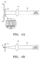
- a mask 12 with a predetermined period ⁇ is disposed apart from an optical fiber 10.
- UV light 16 emitted from a light source is focused in a perpendicular direction to the length of the optical fiber 10 using a cylindrical concave lens 14.
- fiber gratings with one wavelength band can be fabricated with the single mask 12.
- the mask 12 must be replaced. Therefore, this method is not effective in cost and convenience.
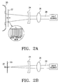
- a projection method using a mask with a predetermined period A is similar to the first method in that fiber gratings are written in an optical fiber with a mask disposed before the optical fiber.
- UV light 28 focused in a perpendicular direction to an optical fiber 20 by a cylindrical convex lens 26 is diverged along the axial direction of the optical fiber 20 through a cylindrical concave lens 24.
- Shadow patterns produced while light diverged through the cylindrical concave lens 24 is passing through a mask 22 are written on the optical fiber 20.
- the period of the shadow patterns on the optical fiber 20 varies by moving the mask 22 to and fro. If the mask 22 approaches the cylindrical concave lens 24, the period of the shadow patterns increases, while if the mask 22 approaches the optical fiber 20, the period of the shadow patterns decreases.
- the multi-period mask using method reduces a diffraction effect by changing the period of a multi-period mask and thus keeping a narrow distance between an optical fiber and the mask if the period of fiber gratings is greater than a predetermined value and thus the mask is spaced from the optical fiber by a predetermined distance.
- UV light 38 focused in a perpendicular direction to the length of an optical fiber 30 by a cylindrical convex lens 36 is diverged along the axial direction of the optical fiber 30 through a cylindrical concave lens 34. While the diverged light is passing through a mask 23, the shadow patterns of the mask 32 are written on the optical fiber 30.
- the period of the shadow patterns on the optical fiber 30 is changed by moving the mask 32 to and fro. If the mask 32 is moved toward the cylindrical concave lens 34, the period increases and if the mask 32 is moved toward the optical fiber 30, the period decreases. Because the single mask 32 has a plurality of periods ⁇ 1, ⁇ 2, and ⁇ 3, an available fiber grating period range is wide enough to fabricate fiber gratings without replacing the mask 32.
- an object of the present invention to provide an optical fiber fabrication apparatus which minimizes a diffraction effect produced by a mask in fabrication of fiber gratings in order to prevent deterioration of the spectrum characteristics of the fiber gratings that might otherwise occur.
- an optical fiber grating fabricating apparatus To fabricate fiber gratings according to one aspect of the present invention, an optical fiber is prepared, a mask with a predetermined period is spaced from the optical fiber, for forming patterns to be used in fabricating gratings on the optical fiber, a UV light source projects UV light in a perpendicular direction to the optical fiber, a lens focuses the UV light, and a mobile concave lens diverges the focused UV light along the length direction of the optical fiber and changes the period of the fiber gratings while moving to and fro.
- an optical fiber is prepared, an integrated multi-period mask is spaced from the optical fiber, for forming patterns to be used in fabricating gratings in a selected period on the optical fiber, a UV light source projects UV light in a perpendicular direction to the optical fiber, a lens focuses the UV light, and a mobile concave lens diverges the focused UV light along the length direction of the optical fiber and changes the period of the fiber gratings while moving to and fro.
- An optical fiber grating fabrication apparatus is applicable to fabrication of fiber gratings using a mask.
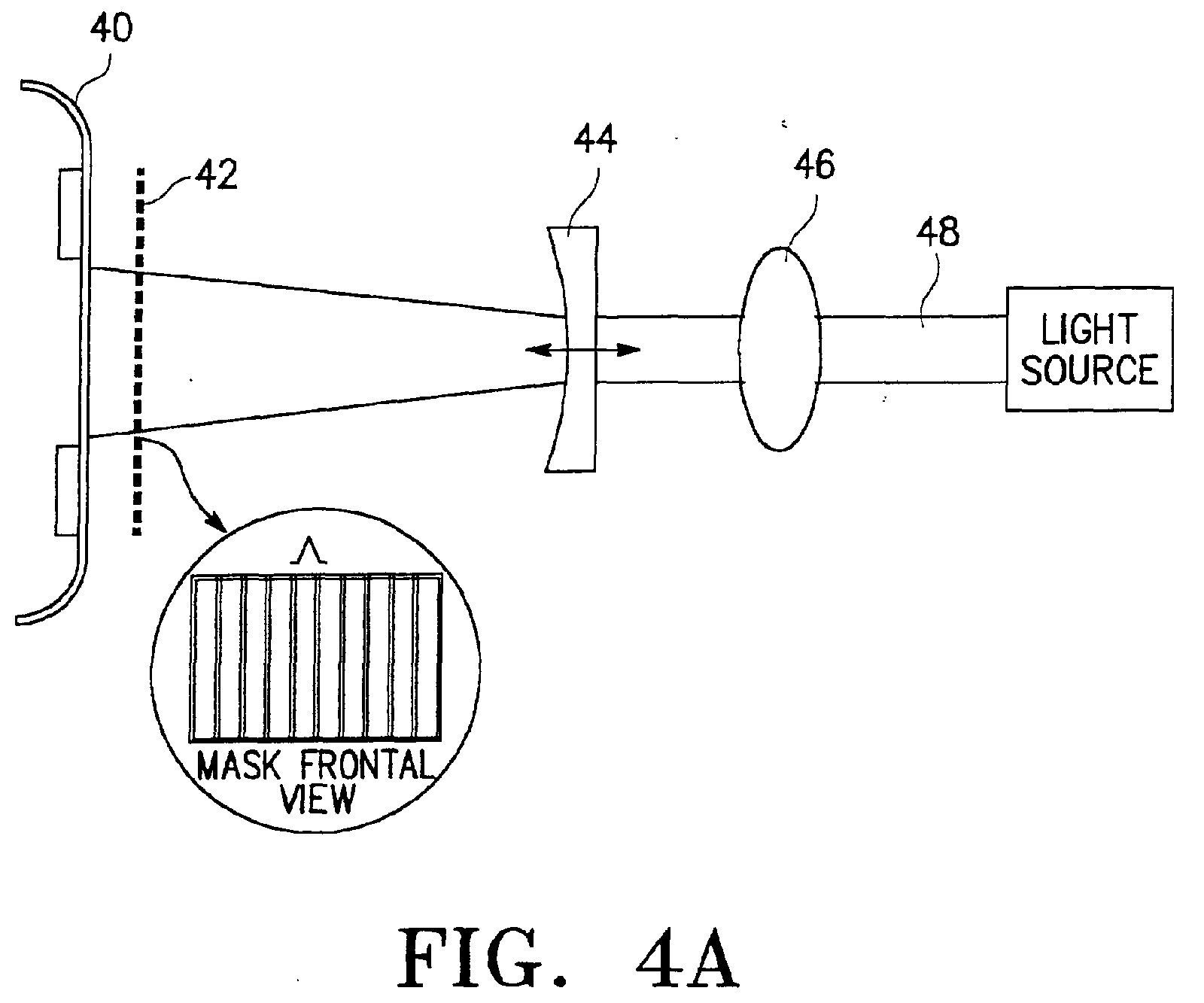
- FIG. 4A is a schematic view of an optical fiber grating fabrication apparatus according to a preferred embodiment of the present invention and FIG. 4B is a side view illustrating the optical fiber grating fabrication apparatus according to the preferred embodiment of the present invention.
- the optical fiber grating fabrication apparatus is comprised of an optical fiber 40 mounted on a support, a mask 42 for forming patterns to be used in fabrication of gratings along the direction of the optical fiber 40, a UV light source for emitting UV light 48, a lens 46 for focusing the UV light 48, and a mobile concave lens 44 for diverging the focused UV light along the axial direction of the optical fiber 40.
- the mask 42 has a predetermined period ⁇ and gratings are also written in the optical fiber 40 in the period ⁇ .
- the mask 42 is fixed at a position spaced from the optical fiber 40, particularly, as near the optical fiber 40 as possible and the fiber grating period ⁇ is changed by moving the mobile concave lens 44.
- the narrow distance between the mask 42 and the optical fiber 40 minimizes a diffraction effect.
- FIG. 5A is a schematic view of an optical fiber grating fabrication apparatus according to another preferred embodiment of the present invention and FIG. 5B is a side view illustrating the optical fiber grating fabrication apparatus according to the second preferred embodiment of the present invention.
- the optical fiber grating fabrication apparatus is comprised of an optical fiber 50 mounted on a support, a mask 52 for forming patterns to be used in fabrication of gratings along the direction of the optical fiber 50, a UV light source for emitting UV light 58, a lens 56 for focusing the UV light 58, and a mobile concave lens 54 for diverging the focused UV light along the axial direction of the optical fiber 50.
- the mask 52 has an integrated multi-period mask with periods ⁇ 1, ⁇ 2, and ⁇ 3 and gratings are written in the optical fiber 40 in a selected period.
- the mask 52 is fixed at a position spaced from the optical fiber 50, particularly, as near the optical fiber 50 as possible and the fiber grating period is changed by moving the mobile concave lens 54.
- the narrow distance between the mask 52 and the optical fiber 50 minimizes a diffraction effect. Since the mask 52 is spaced from the fiber grating 50 by a fixed distance, there is no need for considering changes in processing conditions which were encountered in the conventional fiber grating fabrication process as changes in the distance between a mask and an optical fiber cause different diffraction effects.
- an appropriate period portion of the integrated multi-period mask 52 is selected by adjusting the height of the mask 52. In this manner, fiber gratings can be fabricated lengthwise in the optical fiber in diverse periods.
- a diffraction effect and processing time are reduced and deterioration of the spectrum characteristics of fiber gratings is prevented because the fiber gratings are fabricated with a mask spaced from an optical fiber by a predetermined distance, particularly by a minimum distance. Furthermore, the fixed distance between the mask and the optical fiber removes diffraction variations caused according to the wavelengths of intended fiber gratings. As a result, processing conditions can be estimated relatively accurately, thereby facilitating fabrication of fiber gratings.
Landscapes
- Physics & Mathematics (AREA)
- Engineering & Computer Science (AREA)
- Manufacturing & Machinery (AREA)
- General Physics & Mathematics (AREA)
- Optics & Photonics (AREA)
- Diffracting Gratings Or Hologram Optical Elements (AREA)
- Optical Fibers, Optical Fiber Cores, And Optical Fiber Bundles (AREA)
Abstract
Description
Claims (2)
- An optical fiber grating fabricating apparatus comprising:characterized bya prepared optical fiber (40);a mask (42) with a predetermined period spaced form the optical fiber (40), for forming patterns to be used in fabricating gratings on the optical fiber (40);an ultraviolet (UV) light source for projecting ultraviolet light (48) in a perpendicular direction to the optical fiber (40);a lens (46) for focusing the ultraviolet light (48),a mobile concave lens (44) for diverging the focused ultraviolet light along the length direction of the optical fiber (40) and changing the period of the fiber gratings while moving to and fro.
- An optical fiber grating fabricating apparatus comprising:characterized bya prepared optical fiber (50);an integrated multi-period mask (52) spaced from the optical fiber (50), for forming patterns to be used in fabricating gratings in a selected period on the optical fiber (50);an ultraviolet (UV) light source for projecting ultraviolet light (58) in a perpendicular direction to the optical fiber (50);a lens (56) for focusing the ultraviolet light,a mobile concave lens (54) for diverging the focused ultraviolet light along the length direction of the optical fiber (50) and changing the period of the fiber gratings while moving to and fro.
Applications Claiming Priority (2)
| Application Number | Priority Date | Filing Date | Title |
|---|---|---|---|
| KR2000042700 | 2000-07-25 | ||
| KR1020000042700A KR100342493B1 (en) | 2000-07-25 | 2000-07-25 | Optical fiber grating fabricating apparatus for minimizing diffraction effect |
Publications (3)
| Publication Number | Publication Date |
|---|---|
| EP1191366A2 true EP1191366A2 (en) | 2002-03-27 |
| EP1191366A3 EP1191366A3 (en) | 2002-04-17 |
| EP1191366B1 EP1191366B1 (en) | 2004-03-03 |
Family
ID=19679775
Family Applications (1)
| Application Number | Title | Priority Date | Filing Date |
|---|---|---|---|
| EP01117381A Expired - Lifetime EP1191366B1 (en) | 2000-07-25 | 2001-07-18 | Optical fibre grating fabrication apparatus which minimizes diffraction effects |
Country Status (5)
| Country | Link |
|---|---|
| US (1) | US20020018621A1 (en) |
| EP (1) | EP1191366B1 (en) |
| JP (1) | JP2002090519A (en) |
| KR (1) | KR100342493B1 (en) |
| DE (1) | DE60102194T2 (en) |
Families Citing this family (4)
| Publication number | Priority date | Publication date | Assignee | Title |
|---|---|---|---|---|
| KR100415426B1 (en) * | 2002-02-28 | 2004-01-16 | 광주과학기술원 | Enhanced fabrication of symmetric optical fiber grating using a reflector |
| US8094982B2 (en) * | 2007-03-08 | 2012-01-10 | Oclaro (North America), Inc. | Fiber lens assembly for optical device |
| WO2016004511A1 (en) * | 2014-07-11 | 2016-01-14 | National Research Council Of Canada | Forming an optical grating with an apparatus providing an adjustable interference pattern |
| CN104216598A (en) * | 2014-08-29 | 2014-12-17 | 合肥鑫晟光电科技有限公司 | Touch substrate, manufacturing method of touch substrate and touch display device |
Family Cites Families (7)
| Publication number | Priority date | Publication date | Assignee | Title |
|---|---|---|---|---|
| US5327515A (en) * | 1993-01-14 | 1994-07-05 | At&T Laboratories | Method for forming a Bragg grating in an optical medium |
| IT1292316B1 (en) * | 1997-05-20 | 1999-01-29 | Cselt Centro Studi Lab Telecom | PROCEDURE AND DEVICE FOR THE CREATION OF FIBER BRAGG GRATINGS OR OPTICAL WAVE GUIDES. |
| GB9722550D0 (en) * | 1997-10-24 | 1997-12-24 | Univ Southampton | Fabrication of optical waveguide gratings |
| WO2000011509A1 (en) * | 1998-08-19 | 2000-03-02 | Samsung Electronics Co., Ltd. | Apparatus for manufacturing long-period fiber gratings and apparatus for manufacturing two-band long-period fiber gratings using the same |
| AU761179B2 (en) * | 1998-10-30 | 2003-05-29 | Corning Incorporated | Wavelength tuning of photo-induced gratings |
| KR100318903B1 (en) * | 2000-01-14 | 2001-12-29 | 윤종용 | Long period optical fiber grating |
| KR100417157B1 (en) * | 2001-05-10 | 2004-02-05 | 한국과학기술연구원 | Optical grating coder for use in optical code division multiple access, fabricating method and apparatus therefor |
-
2000
- 2000-07-25 KR KR1020000042700A patent/KR100342493B1/en not_active Expired - Fee Related
-
2001
- 2001-07-18 DE DE60102194T patent/DE60102194T2/en not_active Expired - Fee Related
- 2001-07-18 EP EP01117381A patent/EP1191366B1/en not_active Expired - Lifetime
- 2001-07-18 JP JP2001218611A patent/JP2002090519A/en active Pending
- 2001-07-23 US US09/911,004 patent/US20020018621A1/en not_active Abandoned
Also Published As
| Publication number | Publication date |
|---|---|
| KR20020019621A (en) | 2002-03-13 |
| US20020018621A1 (en) | 2002-02-14 |
| EP1191366B1 (en) | 2004-03-03 |
| KR100342493B1 (en) | 2002-06-28 |
| EP1191366A3 (en) | 2002-04-17 |
| JP2002090519A (en) | 2002-03-27 |
| DE60102194T2 (en) | 2004-07-29 |
| DE60102194D1 (en) | 2004-04-08 |
Similar Documents
| Publication | Publication Date | Title |
|---|---|---|
| Grobnic et al. | Fiber Bragg gratings with suppressed cladding modes made in SMF-28 with a femtosecond IR laser and a phase mask | |
| CA2195259C (en) | Optical signal shaping device for complex spectral shaping applications | |
| US5016967A (en) | Multi-core optical waveguide Bragg grating light redirecting arrangement | |
| CA2311586C (en) | Amplitude mask, and apparatus and method for manufacturing long period grating filter using the same | |
| US5694248A (en) | Spatially-varying distributed Bragg reflectors in optical media | |
| EP3457183B1 (en) | Multicore optical fiber, fiber bragg grating, and method for manufacturing a fiber bragg grating | |
| EP0881515B1 (en) | Spatial filter for high power laser beam | |
| KR20010031375A (en) | Fabrication of optical waveguide gratings | |
| JP2003029062A (en) | Optical fiber with built-in grating and optical fiber for forming grating | |
| AU763596B2 (en) | Apparatus for manufacturing long-period fiber gratings and apparatus for manufacturing two-band long-period fiber gratings using the same | |
| EP1178337A2 (en) | Device for fabricating polarization insensitive long period fiber grating | |
| EP1191366A2 (en) | Optical fibre grating fabrication apparatus which minimizes diffraction effects | |
| KR100315671B1 (en) | Apparatus and method for fabricating multi-period optical fiber grating | |
| GB2394071A (en) | Apparatus and method for producing fibre bragg gratings in a waveguide | |
| EP1555663A3 (en) | Anamorphic prism, optical head and optical recording/reproduction device | |
| KR100342507B1 (en) | Amplitude mask and optical fiber grating manufacturing apparatus using the same | |
| EP0668519A1 (en) | Spatially-varying distributed bragg-reflectors in optical media | |
| JP3281349B2 (en) | Method and apparatus for manufacturing optical fiber grating | |
| AU2002301376B2 (en) | Apparatus for manufacturing two-band long-period fiber gratings using the same | |
| KR100294537B1 (en) | Apparatus for manufacturing long period grating filter | |
| JP2000214316A (en) | Method and apparatus for manufacturing fiber grating | |
| KR19990065145A (en) | Method and apparatus for manufacturing wave filter using amplitude mask | |
| JP2000249849A (en) | Manufacturing method of optical waveguide having grating formed | |
| KR20030005594A (en) | Apparatus for Manufacture of writing optical fiber gratings |
Legal Events
| Date | Code | Title | Description |
|---|---|---|---|
| PUAI | Public reference made under article 153(3) epc to a published international application that has entered the european phase |
Free format text: ORIGINAL CODE: 0009012 |
|
| PUAL | Search report despatched |
Free format text: ORIGINAL CODE: 0009013 |
|
| 17P | Request for examination filed |
Effective date: 20010718 |
|
| AK | Designated contracting states |
Kind code of ref document: A2 Designated state(s): DE FR GB Kind code of ref document: A2 Designated state(s): AT BE CH CY DE DK ES FI FR GB GR IE IT LI LU MC NL PT SE TR |
|
| AX | Request for extension of the european patent |
Free format text: AL;LT;LV;MK;RO;SI |
|
| AK | Designated contracting states |
Kind code of ref document: A3 Designated state(s): AT BE CH CY DE DK ES FI FR GB GR IE IT LI LU MC NL PT SE TR |
|
| AX | Request for extension of the european patent |
Free format text: AL;LT;LV;MK;RO;SI |
|
| 17Q | First examination report despatched |
Effective date: 20020805 |
|
| AKX | Designation fees paid |
Free format text: DE FR GB |
|
| GRAP | Despatch of communication of intention to grant a patent |
Free format text: ORIGINAL CODE: EPIDOSNIGR1 |
|
| GRAS | Grant fee paid |
Free format text: ORIGINAL CODE: EPIDOSNIGR3 |
|
| GRAA | (expected) grant |
Free format text: ORIGINAL CODE: 0009210 |
|
| AK | Designated contracting states |
Kind code of ref document: B1 Designated state(s): DE FR GB |
|
| REG | Reference to a national code |
Ref country code: GB Ref legal event code: FG4D |
|
| REG | Reference to a national code |
Ref country code: IE Ref legal event code: FG4D |
|
| REF | Corresponds to: |
Ref document number: 60102194 Country of ref document: DE Date of ref document: 20040408 Kind code of ref document: P |
|
| ET | Fr: translation filed | ||
| PLBE | No opposition filed within time limit |
Free format text: ORIGINAL CODE: 0009261 |
|
| STAA | Information on the status of an ep patent application or granted ep patent |
Free format text: STATUS: NO OPPOSITION FILED WITHIN TIME LIMIT |
|
| 26N | No opposition filed |
Effective date: 20041206 |
|
| REG | Reference to a national code |
Ref country code: IE Ref legal event code: MM4A |
|
| PGFP | Annual fee paid to national office [announced via postgrant information from national office to epo] |
Ref country code: GB Payment date: 20060712 Year of fee payment: 6 |
|
| PGFP | Annual fee paid to national office [announced via postgrant information from national office to epo] |
Ref country code: DE Payment date: 20060713 Year of fee payment: 6 |
|
| PGFP | Annual fee paid to national office [announced via postgrant information from national office to epo] |
Ref country code: FR Payment date: 20060719 Year of fee payment: 6 |
|
| GBPC | Gb: european patent ceased through non-payment of renewal fee |
Effective date: 20070718 |
|
| PG25 | Lapsed in a contracting state [announced via postgrant information from national office to epo] |
Ref country code: DE Free format text: LAPSE BECAUSE OF NON-PAYMENT OF DUE FEES Effective date: 20080201 |
|
| PG25 | Lapsed in a contracting state [announced via postgrant information from national office to epo] |
Ref country code: GB Free format text: LAPSE BECAUSE OF NON-PAYMENT OF DUE FEES Effective date: 20070718 |
|
| REG | Reference to a national code |
Ref country code: FR Ref legal event code: ST Effective date: 20080331 |
|
| PG25 | Lapsed in a contracting state [announced via postgrant information from national office to epo] |
Ref country code: FR Free format text: LAPSE BECAUSE OF NON-PAYMENT OF DUE FEES Effective date: 20070731 |