EP1191329A2 - Electron spectroscopic analyzer using X-rays - Google Patents
Electron spectroscopic analyzer using X-rays Download PDFInfo
- Publication number
- EP1191329A2 EP1191329A2 EP01308123A EP01308123A EP1191329A2 EP 1191329 A2 EP1191329 A2 EP 1191329A2 EP 01308123 A EP01308123 A EP 01308123A EP 01308123 A EP01308123 A EP 01308123A EP 1191329 A2 EP1191329 A2 EP 1191329A2
- Authority
- EP
- European Patent Office
- Prior art keywords
- rays
- optical system
- emitted
- ray generator
- spectroscopic analyzer
- Prior art date
- Legal status (The legal status is an assumption and is not a legal conclusion. Google has not performed a legal analysis and makes no representation as to the accuracy of the status listed.)
- Withdrawn
Links
Images




Classifications
-
- G—PHYSICS
- G01—MEASURING; TESTING
- G01N—INVESTIGATING OR ANALYSING MATERIALS BY DETERMINING THEIR CHEMICAL OR PHYSICAL PROPERTIES
- G01N23/00—Investigating or analysing materials by the use of wave or particle radiation, e.g. X-rays or neutrons, not covered by groups G01N3/00 – G01N17/00, G01N21/00 or G01N22/00
- G01N23/02—Investigating or analysing materials by the use of wave or particle radiation, e.g. X-rays or neutrons, not covered by groups G01N3/00 – G01N17/00, G01N21/00 or G01N22/00 by transmitting the radiation through the material
- G01N23/06—Investigating or analysing materials by the use of wave or particle radiation, e.g. X-rays or neutrons, not covered by groups G01N3/00 – G01N17/00, G01N21/00 or G01N22/00 by transmitting the radiation through the material and measuring the absorption
- G01N23/083—Investigating or analysing materials by the use of wave or particle radiation, e.g. X-rays or neutrons, not covered by groups G01N3/00 – G01N17/00, G01N21/00 or G01N22/00 by transmitting the radiation through the material and measuring the absorption the radiation being X-rays
-
- G—PHYSICS
- G01—MEASURING; TESTING
- G01N—INVESTIGATING OR ANALYSING MATERIALS BY DETERMINING THEIR CHEMICAL OR PHYSICAL PROPERTIES
- G01N23/00—Investigating or analysing materials by the use of wave or particle radiation, e.g. X-rays or neutrons, not covered by groups G01N3/00 – G01N17/00, G01N21/00 or G01N22/00
- G01N23/22—Investigating or analysing materials by the use of wave or particle radiation, e.g. X-rays or neutrons, not covered by groups G01N3/00 – G01N17/00, G01N21/00 or G01N22/00 by measuring secondary emission from the material
- G01N23/227—Measuring photoelectric effect, e.g. photoelectron emission microscopy [PEEM]
Definitions
- the present invention relates to an electron spectroscopic analyzer using X-rays, and more particularly, to an electron spectroscopic analyzer capable of increasing X-ray transmission efficiency and a signal to noise (S/N) ratio.
- Electron spectroscopic analyzers using X-rays have a variety of industrial applications. Particularly, they are used for obtaining information about the atomic structures and arrays of electrons in atoms of industrially used materials such as semiconductor materials, catalysts and amorphous materials.
- a ratio at which soft X-rays are absorbed into particles in the air can be reduced by connecting an X-ray generator to an optical system using a vacuum bellows whose inside is maintained at a low pressure near to vacuum pressure.
- X-rays are generated by bombarding an X-ray generative sample in the X-ray generator with accelerated electrons.
- electrons are emitted from the X-ray generator and incident on the optical system.
- a signal caused by electrons emitted from the X-ray generator is included in a signal containing information about the object. Accordingly, the S/N ratio is low.
- an electron spectroscopic analyzer includes an X-ray generator for generating X-rays, an optical system for detecting charged particles emitted from an object irradiated with the X-rays to analyze the object, a vacuum system for maintenance at a pressure of 10 -5 torr or less, the vacuum system being provided between the X-ray generator and the optical system, and a blocking unit provided between the X-ray generator and the optical system for preventing elements other than the X-rays emitted from the X-ray generator from flowing into the optical system.
- the vacuum system may be a "vacuum bellows" or other suitable vacuum component for maintaining low pressure.
- elements is not intended to refer simply to elements of the periodic table, but to any wave, particle or component that may be emitted from the X-ray source.
- the present invention provides an electron spectroscopic analyzer using X-rays, which is capable of more accurately analyzing an object by increasing the X-ray transmission efficiency and increasing a signal to noise (S/N) ratio in an analysis signal containing information about the object at which X-rays are radiated.
- S/N signal to noise
- the blocking unit is provided within or outside the bellows.
- the blocking unit may be formed to surround the outside of the bellows.
- the blocking unit may be provided at the outer bottom of the bellows.
- the blocking unit may be provided at an inner portion of the bellows contacting the X-ray generator or an inner portion of the bellows contacting the optical system.
- the blocking unit provided outside the bellows may be a magnet.
- the blocking unit provided at an inner portion of the bellows contacting the X-ray generator or at an inner portion of the bellows contacting the optical system may be a plate formed of a predetermined material which is transparent with respect to X-rays but is opaque with respect to elements other than X-rays emitted from the X-ray generator.
- the plate has a predetermined thickness.
- the blocking unit may be selectively formed at only one of the inner portion of the bellows contacting the X-ray generator and the inner portion of the bellows contacting the optical system.
- the blocking unit provided at the inner portion of the bellows contacting the optical system may be a plate which is transparent with respect to X-rays and other emitted elements and to which power is applied so that an electric field having the same characteristics as an electric field formed from other emitted elements can be formed within the bellows.
- the blocking unit provided at the inner portion of the bellows contacting the optical system may have a center which is transparent with respect to X-rays and a shield around the center which is opaque with respect to X-rays. Power is applied to the blocking unit so that an electric field having the same characteristics as an electric field formed from the other emitted elements can be formed within the bellows.
- Each of the blocking unit provided at the inner portion of the bellows contacting the X-ray generator and the blocking unit provided at the inner portion of the bellows contacting the optical system may be a plate thin enough to be transparent with respect to the X-rays and the other emitted elements from the X-ray generator. However, when the two blocking units are combined, a plate opaque with respect to the other emitted elements is formed.
- the magnet may be an electromagnet and may be composed of at least two independent electromagnets.
- the electron spectroscopic analyzer further includes a collector for collecting elements deflected by the magnet among the emitted elements other than the X-rays, the collector being integrated with the bellows between the magnet and the optical system.
- One of the blocking unit provided at the inner portion of the bellows contacting the X-ray generator and the blocking unit provided at the inner portion of the bellow contacting the optical system is a plate which is transparent with respect to the X-rays and is partially transparent with respect to the emitted elements other than the X-rays, and the other blocking unit is the shield.
- the electron spectroscopic analyzer further includes a bottleneck portion provided in the middle of the bellows for preventing the other emitted elements from flowing into the optical system.
- the present invention is provided with a vacuum bellows between an X-ray generator and an optical system and a blocking unit within or outside of the bellows.
- the blocking unit restrains or blocks inflow of elements other than X-rays emitted from the X-ray generator, particularly charged particles, to the optical system. Accordingly, the S/N ratio in a signal measured in the optical system can be increased, thereby increasing the accuracy of an object analysis. In addition, absorptivity of the X-rays can be reduced, thereby increasing the use efficiency of X-rays.
- reference numeral 40 denotes an X-ray generator for generating X-rays used for analyzing an object.
- Reference numeral 50 denotes an optical system facing the X-ray generator 40.
- the optical system 50 measures a signal corresponding to charged particles, for example, electrons, emitted from an object to be analyzed at which X-rays generated from the X-ray generator 40 are radiated, in order to analyze the object.
- a vacuum system or bellows 60 is provided between the X-ray generator 40 and the optical system 50 to be coupled to both.
- the bellows 60 includes an X-ray inlet (not shown) at its portion contacting the X-ray generator 40 and an X-ray outlet (not shown) at its portion contacting the optical system 50.
- the internal pressure of the bellows 60 is low and near to vacuum pressure so that the amount of X-ray absorbing gas in the bellows 60 is very low. Accordingly, absorption of X-rays, particularly soft X-rays, generated by the X-ray generator 40, while traveling to the optical system 50 can be markedly reduced.
- a first shield 90a is provided at a portion at which the bellows 60 contacts the X-ray generator 40.
- the first shield 90a is an example of a blocking unit for preventing thermal electrons of high energy, which are used by the X-ray generator 40 for emission of X-rays, from flowing out.
- the first shield 90a is formed of a metal having excellent conductivity. Referring to FIG. 2, which is a cross-sectional view taken along the line 2-2N of FIG. 1, a hole "h" is formed in a part of the first shield 90a corresponding to the X-ray inlet of the bellows 60.
- the hole “h” Since thermal electrons in addition to X-rays can be emitted from the X-ray generator 40, it is preferable to form the hole “h” to have a diameter as small as possible in a range in which the X-rays are not blocked.
- the portion of the first shield 90a other than the hole “h” blocks all elements emitted from the X-ray generator 40.
- a second shield 90b is provided at a portion at which the bellows 60 contacts the optical system 50.
- the second shield 90b is an example of a blocking unit for preventing elements other than X-rays emitted from the X-ray generator 40 from flowing into the optical system 50.
- the second shield 90b In contrast to the first shield 90a, the second shield 90b is formed of an insulating material.
- a hole “h1" is formed at the center of the second shield 90b to correspond to the hole "h" of the first shield 90a.
- a third blocking unit besides the first and second shields 90a and 90b may be provided between the X-ray generator 40 and the optical system 50 in order to obtain an accurate result allowing more accurate analysis of an object by increasing an effect of blocking emitted elements other than X-rays, particularly thermal electrons.
- a magnet 100 provided on the bottom of the bellows 60 between the first and second shields 90a and 90b is an example of the third blocking unit.
- the shape of type of the magnet 100 is not limited as long as the magnet 100 has a magnetic field deflecting charged particles, particularly thermal electrons, moving toward the optical system 50 in the bellows 60 away from the optical system 50. Accordingly, the magnet 100 may be a permanent magnet or an electromagnet which satisfies the above condition.
- the magnetic field is formed to be perpendicular to the bellows 60 in order to provoke maximum interaction between the magnetic field and the other emitted elements in the bellows 60. Accordingly, as long as the magnetic field can be formed to be perpendicular to the path of elements traveling toward the optical system 50 in the bellows 60, that is, as long as the magnetic field is perpendicular to the bellows 60, the magnet 100 can be provided at the side, top, bottom or two opposing sides of the bellows 60.
- the second shield 90b is formed of an insulating material, when an element, particularly a charged particle emitted from the X-ray generator 40 other than X-rays, collides with the second shield 90b, a charge-up phenomenon in which a charge is accumulated at a portion of the second shield 90b with which the charged particle collides occurs. Therefore, in the case where the charged particle is a thermal electron which has been used for generation of an X-ray, a charge of a negative polarity which is the same as the thermal electron is accumulated at the second shield 90b, thereby forming an electric field (hereinafter, referred to as a "negative electric field" for clarity) around the second shield 90b. That is, the second shield 90b is the source of the negative electric field.
- an electron spectroscopic analyzer includes a collector 110 for collecting the other emitted elements X1 and X2 at a portion of the wall of the bellows 60 with which the other emitted elements X1 and X2 having passed through the magnetic field region R collide.
- a collector 110 for collecting the other emitted elements X1 and X2 at a portion of the wall of the bellows 60 with which the other emitted elements X1 and X2 having passed through the magnetic field region R collide.
- other emitted elements X1 and X2 collide with the wall of the bellows 60 within the magnetic field region R due to low energy they can be deflected toward the collector 110 by reducing the strength of the magnetic field B or shortening the length of the magnetic field region R.
- an electromagnet is more preferable than a permanent magnet.
- a magnet can be composed of a plurality of independent elements, and the independent elements can be selectively used.
- the magnetic field region R of the magnet 112 can be lengthened or shortened.
- the length of the magnetic field region R becomes maximum.
- the length of the magnetic field region R becomes minimum.
- a third embodiment of the present invention is characterized by an electric field artificially formed within a bellows 60.
- an electron spectroscopic analyzer is provided with first and second shields 90a and 90b as a blocking unit for preventing charged particles emitted from an X-ray generator 40 from being incident on an optical system 50, within the bellows 60.
- power 120 is applied to the second shield 90b, thereby forming a negative electric field within the bellows 60.
- the second shield 90b by applying external power to the second shield 90b, not only are the charged particles prevented from flowing into the optical system 50, but also the second shield 90b is protected from damage due to the collision of charged particles.
- an electron spectroscopic analyzer is provided with a blocking unit for preventing charged particles from entering the optional system 50, the blocking unit including first and second shields 90a and 90b within the bellows 60 and a magnet 100 or 112 outside the bellows 60 for deflects charged particles away from the optical system 50.
- power 130 is applied to the second shield 90b.
- an electron spectroscopic analyzer is provided with a blocking unit for preventing charged particles from entering the optional system 50, the blocking unit including a magnet 100 or 112 for deflecting charged particles away from the optical system 50 outside the bellows 60 and only a second shield 90b within the bellows 60.
- power 140 is applied to the second shield 90b.
- a fourth embodiment of the present invention uses a difference in transmissivity between an X-ray and other emitted element which are generated by an X-ray generator 40 and is characterized by a transparent plate used as a blocking unit, instead of using the first and second shields 90a and 90b.
- a first plate 150a is provided at an inner portion of a bellows 60 contacting the X-ray generator 40
- a second plate 150b is provided at an inner portion of a bellows 60 contacting an optical system 50.
- One of the first and second plates 150a and 150b is transparent with respect to both X-rays and other elements emitted from the X-ray generator 40. However, when the first and second plates 150a and 150 are combined, they are opaque with respect to other elements. Accordingly, X-rays pass through the first plate 150a and then can pass through the second plate 150b. However, other emitted elements, and particularly charged particles, consume their energy due to interaction with particles constituting the first plate 150a while passing through the first plate 150a. As a result, the charged particles which have passed through the first plate 150 do not have enough energy to pass through the second plate 150a and thus can be blocked by the second plate 150b even if they pass through the first plate 150a.
- Such selective characteristics of the first and second plates 150a and 150b as described above are determined according to the materials and thicknesses of the first and second plates 150a and 150b.
- the preferred thickness of each of the first and second plates 150a and 150b is T min /2.
- the thickness of the first plate 150a may be less than T min /2 and the thickness of the second plate 150b may be greater than T min /2, or vice versa, as long as the combined thickness of the first and second plates 150a and 150b is T min .
- the second plate 150b is formed of a material having a density higher than the first plate 150a, it is preferable that the first plate 150a is thicker than the second plate 150b.
- a single plate (referred to as a "third plate” below) having the same thickness as the combined thickness of the first and second plates 150a and 150b can be used.
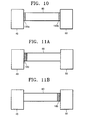
- a third plate 160 is provided at an inner portion of a bellows 60 contacting an X-ray generator 40, as shown in FIG. 11A, or at an inner portion of the bellows 60 contacting an optical system 50, as shown in FIG. 11B.
- a magnet 100 or 112 deflecting charged particles passing through a first plate 150a away from an optical system 50 is provided outside a bellows 60 between the first and second plates 150a and 150b.
- a magnet 100 or 112 deflecting charged particles is provided outside a bellows 60, and a third plate 160 is provided at an inner portion of the bellows contacting the optical system 50.
- a fifth embodiment of the present invention is characterized by an electric field formed within a bellows 60 by applying power 120 to a plate 170.
- the plate 170 is one selected from the second plate 150b and the third plate 160 shown in the fourth embodiment.
- a first plate 150a or a first shield 90a may also be provided at a portion of the bellows 60 which is not shown in FIG. 14.
- a magnet may be further provided for deflecting charged particles.
- An electron spectroscopic analyzer includes one of the first and second shields 90a and 90b and one of the first and second plates 150a and 150b and may selectively include a magnet.
- a plate 180 is provided in an inner portion of a bellows 60 contacting an X-ray generator 40.
- the plate 180 is transparent with respect to X-rays emitted from the X-ray generator 40 but is partially transparent or opaque with respect to other elements, particularly charged particles, emitted from the X-ray generator 40.
- the plate 180 is realized as one of the first and second plates 150a and 150b described in the fourth embodiment.
- a shield 90 is provided in an inner portion of the bellows 60 contacting an optical system 50.
- the shield 190 is provided for preventing charged particles which have passed through the plate 180 from being incident on the optical system 50.
- the shield 190 is realized as the second shield 90b described in the first embodiment.
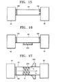
- a magnet 200 for deflecting charged particles which have passed through a plate 180 is provided outside a bellows 60 between the plate 180 and a shield 190.
- a permanent magnet may be used but an electromagnet is preferable.
- a plate 180 is provided in an inner portion of a bellows 60 contacting an X-ray generator 40, and a magnet 210 for forming a magnetic field across the bellows 60 is provided outside the bellows 60 between the plate 180 and an optical system 50.
- a collector 220 for collecting charged particles deflected by the magnet 210 is provided between the magnet 210 and the optical system 50.
- the collector 220 is integrated with the bellows 60.
- reference character B denotes an upward magnetic field formed due to the magnet 210.
- Reference characters X and e denote an X-ray and an electron, respectively, which are emitted from the X-ray generator 40. Since the X-ray X does not have a charge, it is directly incident on the optical system 50 without being influenced by the magnetic field B. In contrast, the electron e is deflected toward the collector 220 due to interaction with the magnetic field B.
- an electric field can be formed within the bellows 60 by applying power to the shield 190 of the electron spectroscopic analyzers shown in FIGS. 15 and 16, thereby increasing an effect of blocking charged particles emitted from the X-ray generator 40.
- Copper (Cu) was analyzed using a conventional electron spectroscopic analyzer including an X-ray generator having power of 1.5 kW (30 kV and 50 mA), and using an electron spectroscopic analyzer according to the first embodiment of the present invention including an X-ray generator having power of 7.5 kW (30 kV and 250 mA).
- a first graph G1 denotes the result when the conventional electron spectroscopic analyzer was used
- a second graph G2 denotes the result when the electron spectroscopic analyzer according to the first embodiment of the present invention was used.
- the horizontal axis denotes the energy of X-rays radiated at the object to be analyzed
- both vertical axes denote the count per unit time of electrons emitted from the object to be analyzed in response to irradiation by the X-rays.
- the vertical axis on the left applies to the second graph G2, and the vertical axis on the right applies to the first graph G1.
- the measured rate of electron emission from the copper in an optical system according to conventional technology was much greater than that in the present invention, even when the power of the X-ray generator of the conventional electron spectroscopic analyzer was as small as 1/5 of the power of the electron spectroscopic analyzer according to the present invention. This is because only electrons emitted from the copper are detected by the electron spectroscopic analyzer of the present invention while both electrons emitted from the copper and electrons emitted from the X-ray generator which are incident on the optical system are detected by the conventional electron spectroscopic analyzer.
- Copper has a K absorption edge of 8.981 KeV. Accordingly, when 8.981 KeV X-rays are radiated at copper, they are readily absorbed, and emission of roughly 8.981 KeV electrons increases, thereby greatly increasing the number of electrons measured by an optical system per unit time. Consequently, it is anticipated that an increases in electron emission will appear on a graph when the energy of the radiated X-rays becomes 8.981 KeV.
- the 8.981 KeV absorption edge of copper does not appear in the first graph G1.
- the energy value of a radiated X-ray becomes 8.98 KeV, the absorption edge is quite visible.
- Such a sign does not appear in the first graph G1 because electrons emitted from copper are mixed with electrons of high energy continuously emitted from an X-ray generator and incident on an optical system when the energy of the X-rays becomes 8.98 KeV. Accordingly, it is difficult to discriminate a signal corresponding to electrons emitted from the copper from an entire measured signal.
- Elements other than X-rays emitted from an X-ray generator 40 can be blocked by the bottleneck portion 250. Even if the other emitted elements, for example, electrons, pass through the bottleneck portion 250, the other emitted elements are deflected away from an optical system 50 due to a magnetic field formed across the bottleneck portion 250 by the magnet 260.
- a cooling unit may be provided between the magnet 260 and the bottleneck portion 250 to cool down the heated bottleneck portion 250.
- Numerous variations of electron spectroscopic analyzers obtained by combining electron spectroscopic analyzers according to the first through sixth embodiments may be implemented.
- the present invention is provided with a vacuum bellows, the inside of which is maintained at a low pressure near to vacuum pressure, between an X-ray generator and an optical system. Accordingly, absorption of X-rays by gas within the bellows can be reduced, thereby increasing the X-ray transmission efficiency.
- a unit for restricting or blocking inflow of elements other than X-rays emitted from the X-ray generator, particularly charged particles, into the optical system is provided within or outside the bellows. Therefore, the S/N ratio of a signal measured in the optical system of an electron spectroscopic analyzer is increased, thereby increasing the accuracy and precision of X-ray absorption analysis.
Landscapes
- Health & Medical Sciences (AREA)
- Physics & Mathematics (AREA)
- Life Sciences & Earth Sciences (AREA)
- Chemical & Material Sciences (AREA)
- Analytical Chemistry (AREA)
- Biochemistry (AREA)
- General Health & Medical Sciences (AREA)
- General Physics & Mathematics (AREA)
- Immunology (AREA)
- Pathology (AREA)
- Toxicology (AREA)
- Analysing Materials By The Use Of Radiation (AREA)
Abstract
Description
characterized by an electric field formed within a
Claims (13)
- An electron spectroscopic analyzer using X-rays comprising:an X-ray generator for generating X-rays;an optical system for detecting charged particles emitted from an object irradiated with the X-rays to analyze the object;a vacuum system whose inside is maintained at a pressure of 10-5 torr or less, the vacuum system being provided between the X-ray generator and the optical system; andblocking means provided between the X-ray generator and the optical system for substantially preventing elements emitted from the X-ray generator other than the emitted X-rays from flowing into the optical system.
- The electron spectroscopic analyzer of claim 1, wherein the blocking means is provided within or outside the vacuum system.
- The electron spectroscopic analyzer of claim 2, wherein the blocking means is a magnet provided at the outer surface of the vacuum system.
- The electron spectroscopic analyzer of claim 2, wherein the blocking means is provided at an inner portion of the vacuum system contacting the X-ray generator or an inner portion of the vacuum system contacting the optical system.
- The electron spectroscopic analyzer of claim 4, wherein at least one of the blocking means provided at the inner portion of the vacuum system contacting the X-ray generator and the blocking means provided at the inner portion of the vacuum system contacting the optical system is a plate which is transparent with respect to the X-rays but is opaque with respect to the emitted elements other than the X-rays.
- The electron spectroscopic analyzer of claim 5, wherein power is applied to the plate provided at the inner portion of the vacuum system contacting the optical system so that an electric field having the same characteristics as an electric field formed due to the emitted elements other than the X-rays can be formed.
- The electron spectroscopic analyzer of claim 4, wherein the blocking means provided at the inner portion of the vacuum system contacting the optical system includes a hole at the center thereof and a shield which is provided around the hole and is opaque with respect to the X-rays and the other emitted elements.
- The electron spectroscopic analyzer of claim 7, wherein power is applied to the shield so that an electric field having the same characteristics as an electric field formed due to the elements other than the X-rays emitted from the X-ray generator can be formed.
- The electron spectroscopic analyzer of claim 4, wherein the blocking means provided at the inner portion of the vacuum system contacting the optical system is a plate which is transparent with respect to the X-rays and is opaque with respect to the other elements emitted from the X-ray generator.
- The electron spectroscopic analyzer of claim 3, wherein the magnet is a compound electromagnet composed of at least two independent electromagnets.
- The electron spectroscopic analyzer of claim 3, further comprising a collector for collecting elements deflected by the magnet among the emitted elements other than the X-rays, the collector being integrated with the vacuum system between the magnet and the optical system.
- The electron spectroscopic analyzer of claim 7, wherein one of the blocking means provided at the inner portion of the vacuum system contacting the X-ray generator and the blocking means provided at the inner portion of the vacuum system contacting the optical system is a plate which is transparent with respect to the X-rays and is partially transparent with respect to the emitted elements other than the X-rays, and the other blocking means is the shield.
- The electron spectroscopic analyzer of claim 1, further comprising a bottleneck portion provided in the middle of the vacuum system for preventing the other emitted elements from flowing into the optical system.
Applications Claiming Priority (2)
| Application Number | Priority Date | Filing Date | Title |
|---|---|---|---|
| KR2000056152 | 2000-09-25 | ||
| KR10-2000-0056152A KR100382760B1 (en) | 2000-09-25 | 2000-09-25 | Electron spectroscopic analyzer using X-ray |
Publications (2)
| Publication Number | Publication Date |
|---|---|
| EP1191329A2 true EP1191329A2 (en) | 2002-03-27 |
| EP1191329A3 EP1191329A3 (en) | 2003-10-22 |
Family
ID=19690244
Family Applications (1)
| Application Number | Title | Priority Date | Filing Date |
|---|---|---|---|
| EP01308123A Withdrawn EP1191329A3 (en) | 2000-09-25 | 2001-09-25 | Electron spectroscopic analyzer using X-rays |
Country Status (4)
| Country | Link |
|---|---|
| US (1) | US6653628B2 (en) |
| EP (1) | EP1191329A3 (en) |
| JP (1) | JP2002148229A (en) |
| KR (1) | KR100382760B1 (en) |
Cited By (1)
| Publication number | Priority date | Publication date | Assignee | Title |
|---|---|---|---|---|
| CN110235219A (en) * | 2017-02-03 | 2019-09-13 | 加坦公司 | Harmonic line noise compensation for electron energy loss spectrometer |
Families Citing this family (8)
| Publication number | Priority date | Publication date | Assignee | Title |
|---|---|---|---|---|
| US6956928B2 (en) * | 2003-05-05 | 2005-10-18 | Bruker Axs, Inc. | Vertical small angle x-ray scattering system |
| KR20050043257A (en) * | 2003-11-05 | 2005-05-11 | 삼성전자주식회사 | 3 dimensional surface analysis method |
| DE102004039763B4 (en) * | 2004-08-17 | 2007-07-19 | Infineon Technologies Ag | Method for determining the thickness of a layer |
| GB2442485B (en) * | 2006-10-03 | 2008-12-10 | Thermo Electron Corp | X-ray photoelectron spectroscopy analysis system for surface analysis and method therefor |
| US8217577B2 (en) * | 2009-08-31 | 2012-07-10 | L-3 Communications Corporation | Hybrid modulation in an emission-gated electron gun |
| US8999765B2 (en) * | 2013-06-25 | 2015-04-07 | Intel Corporation | Methods to prevent filler entrapment in microelectronic device to microelectronic substrate interconnection structures |
| CN108593688B (en) * | 2018-07-10 | 2024-03-29 | 中国科学技术大学 | Partial electron yield detection device for synchrotron radiation soft X-ray absorption spectroscopy |
| JP7485996B1 (en) * | 2023-02-27 | 2024-05-17 | 株式会社Nhvコーポレーション | Electron beam irradiation equipment |
Family Cites Families (11)
| Publication number | Priority date | Publication date | Assignee | Title |
|---|---|---|---|---|
| US3822382A (en) * | 1971-08-17 | 1974-07-02 | Jeol Ltd | Apparatus for analyzing electron energy |
| US3969629A (en) * | 1975-03-14 | 1976-07-13 | Varian Associates | X-ray treatment machine having means for reducing secondary electron skin dose |
| US4109154A (en) * | 1977-03-18 | 1978-08-22 | Applied Radiation | X-ray beam compensation |
| JPS5981546A (en) * | 1982-10-30 | 1984-05-11 | Shimadzu Corp | X-ray photoelectron analyzer |
| US4837794A (en) * | 1984-10-12 | 1989-06-06 | Maxwell Laboratories Inc. | Filter apparatus for use with an x-ray source |
| FR2600422B1 (en) * | 1986-05-29 | 1989-10-13 | Instruments Sa | APPARATUS AND METHOD FOR LOCAL CHEMICAL ANALYSIS ON THE SURFACE OF SOLID MATERIALS BY X-RAY PHOTO-ELECTRON SPECTROSCOPY |
| JPH0766774B2 (en) * | 1989-04-27 | 1995-07-19 | 株式会社島津製作所 | Sample surface analyzer |
| US5650616A (en) * | 1992-04-14 | 1997-07-22 | Olympus Optical Co., Ltd. | Apparatus and method for analyzing surface |
| US5444242A (en) * | 1992-09-29 | 1995-08-22 | Physical Electronics Inc. | Scanning and high resolution electron spectroscopy and imaging |
| US5329569A (en) * | 1993-02-18 | 1994-07-12 | Sandia Corporation | X-ray transmissive debris shield |
| US6326617B1 (en) * | 1997-09-04 | 2001-12-04 | Synaptic Pharmaceutical Corporation | Photoelectron spectroscopy apparatus |
-
2000
- 2000-09-25 KR KR10-2000-0056152A patent/KR100382760B1/en not_active Expired - Fee Related
-
2001
- 2001-09-25 JP JP2001290673A patent/JP2002148229A/en active Pending
- 2001-09-25 EP EP01308123A patent/EP1191329A3/en not_active Withdrawn
- 2001-09-25 US US09/960,963 patent/US6653628B2/en not_active Expired - Fee Related
Cited By (2)
| Publication number | Priority date | Publication date | Assignee | Title |
|---|---|---|---|---|
| CN110235219A (en) * | 2017-02-03 | 2019-09-13 | 加坦公司 | Harmonic line noise compensation for electron energy loss spectrometer |
| CN110235219B (en) * | 2017-02-03 | 2021-10-29 | 加坦公司 | Harmonic Line Noise Correction for Electron Energy Loss Spectrometers |
Also Published As
| Publication number | Publication date |
|---|---|
| KR20020024413A (en) | 2002-03-30 |
| US20020040970A1 (en) | 2002-04-11 |
| KR100382760B1 (en) | 2003-05-01 |
| EP1191329A3 (en) | 2003-10-22 |
| US6653628B2 (en) | 2003-11-25 |
| JP2002148229A (en) | 2002-05-22 |
Similar Documents
| Publication | Publication Date | Title |
|---|---|---|
| Bederson et al. | Total Electron—Atom Collision Cross Sections at Low Energies—A Critical Review | |
| EP1703537B9 (en) | Analysing system and charged particle beam device | |
| JP2886508B2 (en) | Charged particle detector and mass spectrometer using the same | |
| EP1191329A2 (en) | Electron spectroscopic analyzer using X-rays | |
| Lindl et al. | Field emission of α particles during scission of161Ho, 169ta compound nuclei | |
| Hanstorp | An ion beam apparatus for collinear photodetachment experiments | |
| US5026988A (en) | Method and apparatus for time of flight medium energy particle scattering | |
| US4649279A (en) | Negative ion source | |
| LU102015B1 (en) | Magnetic sector with a shunt for a mass spectrometer | |
| JPH0313702B2 (en) | ||
| JP3585789B2 (en) | Material evaluation apparatus and method using positron | |
| Tserruya et al. | Hadron blind Cherenkov counters | |
| JP2005195559A (en) | Particle distribution evaluation method and apparatus, laser profile measurement method and apparatus, particle collection method and apparatus | |
| US5689112A (en) | Apparatus for detection of surface contaminations on silicon wafers | |
| JPH0368503B2 (en) | ||
| US3388359A (en) | Particle beam focussing magnet with a septum wall | |
| US3681599A (en) | Sector-type charged particle energy analyzer | |
| Ruoff et al. | Versatile apparatus for electron impact ionization experiments at high energies (500 keV) | |
| JP4073839B2 (en) | Magnetic field generator for analyzer | |
| Lunney et al. | AD-7/GBAR status report for the 2023 CERN SPSC | |
| Buchenauer et al. | Measuring the escaping beam ions from a tokamak plasma | |
| Arauzo et al. | Proposal of a Gas-Ionization BSM for the LHC | |
| Ogawa et al. | Development of Faraday-cup-based Fast Ion Loss Detector in Wendelstein 7-X | |
| JPH09304539A (en) | Electronic detector | |
| WO2022145263A1 (en) | Ion beam analysis device |
Legal Events
| Date | Code | Title | Description |
|---|---|---|---|
| PUAI | Public reference made under article 153(3) epc to a published international application that has entered the european phase |
Free format text: ORIGINAL CODE: 0009012 |
|
| AK | Designated contracting states |
Kind code of ref document: A2 Designated state(s): AT BE CH CY DE DK ES FI FR GB GR IE IT LI LU MC NL PT SE TR |
|
| AX | Request for extension of the european patent |
Free format text: AL;LT;LV;MK;RO;SI |
|
| RIN1 | Information on inventor provided before grant (corrected) |
Inventor name: LIM, CHANG-BIN Inventor name: YURYEV, YURY N., C/O SAMSUNG ADVANCED INSTITUTE O Inventor name: LEE, JAE-CHEOL, 104-905 SAMCHEONRI 1-CHA APT. |
|
| PUAL | Search report despatched |
Free format text: ORIGINAL CODE: 0009013 |
|
| AK | Designated contracting states |
Kind code of ref document: A3 Designated state(s): AT BE CH CY DE DK ES FI FR GB GR IE IT LI LU MC NL PT SE TR |
|
| AX | Request for extension of the european patent |
Extension state: AL LT LV MK RO SI |
|
| RIC1 | Information provided on ipc code assigned before grant |
Ipc: 7G 01N 23/227 B Ipc: 7H 01J 49/44 B Ipc: 7G 21K 1/10 B Ipc: 7G 21K 1/08 A |
|
| 17P | Request for examination filed |
Effective date: 20040225 |
|
| AKX | Designation fees paid |
Designated state(s): DE FR GB |
|
| 17Q | First examination report despatched |
Effective date: 20080911 |
|
| STAA | Information on the status of an ep patent application or granted ep patent |
Free format text: STATUS: THE APPLICATION IS DEEMED TO BE WITHDRAWN |
|
| 18D | Application deemed to be withdrawn |
Effective date: 20090122 |