EP1191302A2 - Heat exchanger - Google Patents
Heat exchanger Download PDFInfo
- Publication number
- EP1191302A2 EP1191302A2 EP01122764A EP01122764A EP1191302A2 EP 1191302 A2 EP1191302 A2 EP 1191302A2 EP 01122764 A EP01122764 A EP 01122764A EP 01122764 A EP01122764 A EP 01122764A EP 1191302 A2 EP1191302 A2 EP 1191302A2
- Authority
- EP
- European Patent Office
- Prior art keywords
- refrigerant
- heat exchanger
- refrigerant flow
- space
- portions
- Prior art date
- Legal status (The legal status is an assumption and is not a legal conclusion. Google has not performed a legal analysis and makes no representation as to the accuracy of the status listed.)
- Granted
Links
Images




Classifications
-
- F—MECHANICAL ENGINEERING; LIGHTING; HEATING; WEAPONS; BLASTING
- F28—HEAT EXCHANGE IN GENERAL
- F28F—DETAILS OF HEAT-EXCHANGE AND HEAT-TRANSFER APPARATUS, OF GENERAL APPLICATION
- F28F9/00—Casings; Header boxes; Auxiliary supports for elements; Auxiliary members within casings
- F28F9/02—Header boxes; End plates
- F28F9/026—Header boxes; End plates with static flow control means, e.g. with means for uniformly distributing heat exchange media into conduits
- F28F9/027—Header boxes; End plates with static flow control means, e.g. with means for uniformly distributing heat exchange media into conduits in the form of distribution pipes
-
- F—MECHANICAL ENGINEERING; LIGHTING; HEATING; WEAPONS; BLASTING
- F28—HEAT EXCHANGE IN GENERAL
- F28D—HEAT-EXCHANGE APPARATUS, NOT PROVIDED FOR IN ANOTHER SUBCLASS, IN WHICH THE HEAT-EXCHANGE MEDIA DO NOT COME INTO DIRECT CONTACT
- F28D1/00—Heat-exchange apparatus having stationary conduit assemblies for one heat-exchange medium only, the media being in contact with different sides of the conduit wall, in which the other heat-exchange medium is a large body of fluid, e.g. domestic or motor car radiators
- F28D1/02—Heat-exchange apparatus having stationary conduit assemblies for one heat-exchange medium only, the media being in contact with different sides of the conduit wall, in which the other heat-exchange medium is a large body of fluid, e.g. domestic or motor car radiators with heat-exchange conduits immersed in the body of fluid
- F28D1/03—Heat-exchange apparatus having stationary conduit assemblies for one heat-exchange medium only, the media being in contact with different sides of the conduit wall, in which the other heat-exchange medium is a large body of fluid, e.g. domestic or motor car radiators with heat-exchange conduits immersed in the body of fluid with plate-like or laminated conduits
- F28D1/0308—Heat-exchange apparatus having stationary conduit assemblies for one heat-exchange medium only, the media being in contact with different sides of the conduit wall, in which the other heat-exchange medium is a large body of fluid, e.g. domestic or motor car radiators with heat-exchange conduits immersed in the body of fluid with plate-like or laminated conduits the conduits being formed by paired plates touching each other
- F28D1/0325—Heat-exchange apparatus having stationary conduit assemblies for one heat-exchange medium only, the media being in contact with different sides of the conduit wall, in which the other heat-exchange medium is a large body of fluid, e.g. domestic or motor car radiators with heat-exchange conduits immersed in the body of fluid with plate-like or laminated conduits the conduits being formed by paired plates touching each other the plates having lateral openings therein for circulation of the heat-exchange medium from one conduit to another
- F28D1/0333—Heat-exchange apparatus having stationary conduit assemblies for one heat-exchange medium only, the media being in contact with different sides of the conduit wall, in which the other heat-exchange medium is a large body of fluid, e.g. domestic or motor car radiators with heat-exchange conduits immersed in the body of fluid with plate-like or laminated conduits the conduits being formed by paired plates touching each other the plates having lateral openings therein for circulation of the heat-exchange medium from one conduit to another the plates having integrated connecting members
- F28D1/0341—Heat-exchange apparatus having stationary conduit assemblies for one heat-exchange medium only, the media being in contact with different sides of the conduit wall, in which the other heat-exchange medium is a large body of fluid, e.g. domestic or motor car radiators with heat-exchange conduits immersed in the body of fluid with plate-like or laminated conduits the conduits being formed by paired plates touching each other the plates having lateral openings therein for circulation of the heat-exchange medium from one conduit to another the plates having integrated connecting members with U-flow or serpentine-flow inside the conduits
Definitions
- the present invention relates to a heat exchanger which is used for an air conditioner.
- Figs. 7 to 14 show examples of structures of heat exchangers which are used as evaporators for vehicular air conditioners and the like.
- the heat exchangers shown in these figures are called drawn-cup type heat exchangers, and each air conditioner is constructed by alternately overlaying plate shaped refrigerant passage portions and corrugated plate shaped cooling fins.
- reference numeral 11 denotes the refrigerant flow portions and reference numeral 12 denotes the cooling fins.
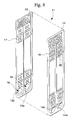
- the refrigerant flow portion 11 is obtained by overlaying substantially rectangular flat plates 13 and 14 which are formed by drawing, and brazing at the outer peripheral portions and the central portions thereof.
- a refrigerant inlet 15 and a refrigerant outlet 16 are provided side by side at the lower end part of the refrigerant flow portion 11, and an inverted U-shaped refrigerant flow path R which extends upwardly from the refrigerant inlet 15 and turns downwards at the top of the refrigerant flow portion 11 toward the refrigerant outlet 16, is formed within the refrigerant flow portion 11.
- a plurality of dimples 17 are formed in the refrigerant flow portion 11 by denting the flat plates 13 and 14 which form the refrigerant flow path R from the outside, and these dimples 17 form a plurality of bulged portions 18 in the refrigerant flow path R. Furthermore, the left end of the laminated refrigerant flow portions 11 and cooling fins 12 are covered by a side plate 19.
- proximal end the left end of each figure
- distal end the right end of each Figure is referred to "distal end”.
- the refrigerant inlet 15 is composed of opening portions 13a and 14a formed in the flat plates 13 and 14, and the refrigerant inlets 15 of the respective refrigerant flow portions 11 are directly overlaid with no intervening cooling fin 12, so that a continuous space Sa is formed.
- the refrigerant outlet 16 is composed of opening portions 13a and 14a formed in the flat plates 13 and 14, and the refrigerant outlets 16 of the respective refrigerant flow portions 11 are directly overlaid with no intervening cooling fins 12, so that a continuous space Sb is formed.
- the proximal end of the space Sa is connected with a refrigerant inlet pipe 20 which extends from the central part of the height of the heat exchanger, and the proximal end of the space Sb is connected with a refrigerant outlet pipe 21. Furthermore, the distal end of each space Sa, Sb is closed by a cover which is not shown in Figures.
- refrigerant which flows into the space Sa through the refrigerant inlet pipe 20 is distributed to each of the refrigerant flow paths R, undergoes heat exchange while it passes through the refrigerant flow paths R, and then is collected at the space Sb and exits from the refrigerant outlet pipe 21.
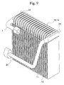
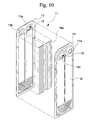
- the heat exchanger shown in Figs. 9 to 11 provides the refrigerant inlet 15 and the refrigerant outlet 16 at the upper end part of the refrigerant flow portion 11, and a U-shaped refrigerant flow path R which extends downwards from the refrigerant inlet 15 and turns upwards at the bottom of the refrigerant flow portion 11 towards the refrigerant outlet 16 is formed within the refrigerant flow portion 11. Furthermore, in this air conditioner, the bulged portions 18 are not provided, and a corrugated inner fin 18a is sandwiched between each of the flat plates 13 and 14.
- the proximal end of the space Sa is connected with the refrigerant inlet pipe 20 via a header 22, and the distal end of the space Sb is connected with the refrigerant outlet pipe 21 via a header 23.
- refrigerant which flows into the space Sa from the refrigerant inlet pipe 20 through the header 22 is distributed to each of the refrigerant flow paths R, undergoes heat exchange while passing through the refrigerant flow path R, and then is collected at the space Sb and exists from the refrigerant outlet pipe 21.
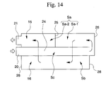
- the heat exchanger shown in Figs. 12 to 14 further provides an opening 24 which opens adjacent to each refrigerant inlet 15 and refrigerant outlet 16, and the openings 24 of the refrigerant flow portions 11 are overlaid with no intervening cooling fins 12 so that a continuous space (forward flow path) Sc is formed.
- the space Sa is divided into two spaces Sa-1 and Sa-2 in the longitudinal direction by a partitioning wall 25.
- a cover 26 is fixed on the distal end of the heat exchanger, so that a turning portion 27 which connects the distal ends of spaces Sc and Sa-1 is formed by the cover 26.
- the proximal end of the space Sc is connected with the refrigerant inlet pipe 20 and the proximal end of the space Sa is connected with the refrigerant outlet pipe 21, and both ends of the space Sb are closed by covers 28.
- the flow of the refrigerant which flows into the space Sc through the refrigerant inlet pipe 20 is turned at the turning portion 27 and flows into the space Sa-1 and is distributed to the refrigerant flow portions 11 at the distal end side of the heat exchanger.
- the refrigerant undergoes heat exchange while it passes through each of the refrigerant flow paths R, and is collected at the space Sb.
- the refrigerant is further distributed to the refrigerant flow portions 11 at the proximal end side of the heat exchanger and passes through each refrigerant flow path R, and is collected at the space Sa-2, and then, the refrigerant exists from the refrigerant outlet pipe 21.
- the refrigerant inlet pipe 20 has a 90 degree curve adjacent to the space Sa as denoted by symbol A in Fig. 7 for example, the flow of the refrigerant is slowed down due to the curve, and therefore, the refrigerant may not reach the innermost regions (the distal end part) of the space Sa, and the refrigerant may not flow to the distal end part of the space Sa.
- the refrigerant may not be uniformly distributed throughout the respective refrigerant flow paths R, and consequently, the problem that heat exchange is not sufficient at the refrigerant flow paths R at the distal end part may occur.
- the heat exchangers as described above are manufactured by braze welding.
- the refrigerant flow portion 11 is constructed by brazing the flat plates 13 and 14 at flange portions 13c and 14c which are provided on the outer peripheral portions thereof as shown in Fig. 11.
- adjacent refrigerant inlets 15 are fastened by brazing a flange-shaped side wall 13d which is formed at each opening portion 13a (or 14b) and a flange-shaped side wall 14d which is formed at adjacent opening portion 14a (or 13b).
- the fastening positions of the refrigerant inlets 15 or refrigerant outlets 16 protrude into the space Sa or Sb and give rise to resistance to the flow of fluid (refrigerant) in the space Sa or Sb.
- the pressure loss of the fluid which passes the space Sa or Sb caused by the resistance increases to a significant level, and the heat exchange capacity of the heat exchanger decreases.
- the cooling fins 12 and flat plates 13, 14 have become thinner, in compliance with the demand for reducing the weight and size of the heat exchanger.
- the present invention was made in consideration of the above-mentioned circumstances, and a first object of the present invention is to uniformly distribute the refrigerant in the space Sa and improve the heat exchange capacity of the heat exchanger. Further, a second object of the present invention is to reduce the pressure loss of the refrigerant in the space Sa or Sb and improve the heat exchange capacity of the heat exchanger. Furthermore, a third object of the present invention is to provide the heat exchanger with a reduced weight and a minimized size while maintaining the strength of the turning portion 27.
- the present invention relates to a heat exchanger in which a plate-shaped refrigerant flow portion which provides an internal refrigerant flow path by overlaying two flat plates formed by drawing and a cooling fin are alternately layered; comprising an opening portion provided on each of the flat plates and which is connected with the refrigerant flow path, and a continuous space for the flow of the refrigerant which is provided by connecting the opening portions of adjacent refrigerant flow portions; wherein the refrigerant which flows in the space is distributed to the respective refrigerant flow paths through the opening portions.
- the heat exchanger of the present invention is characterized by comprising a means for improving the heat exchange capacity.
- This means is a narrowing means which is provided at an upstream end part of the space in order to uniformly distribute the refrigerant to the respective refrigerant flow paths, for example.
- a rectifier which rectifies the flow of the refrigerant along the longitudinal direction of the space at a downstream end side of the space, and it is further preferable to provide the rectifier adjacent to the narrowing means.
- a tubular portion which projects substantially perpendicularly to the flat plates may be provided at each of the opening portions of the respective refrigerant flow portions as the means for improving the heat exchange capacity.
- the tubular portion which is provided at one of the refrigerant flow portions is inserted into the tubular portion of the adjacent refrigerant flow portion so as to closely seal the outer and inner peripheral surface of these tubular portions.
- the diameter of an end part of the tubular portion of the adjacent refrigerant flow portion has a uniform diameter which is larger than that of the inserted tubular portion, or to have a diameter which is gradually enlarged in the longitudinal direction so as to be larger than that of the inserted tubular portion.
- the present invention is also characterized by comprising a forward flow path in which the refrigerant flows from the proximal end of the heat exchanger to the distal end thereof, and a turning portion which is provided at the distal end and the direction of flow of the refrigerant which flows from the forward flow path to the space; wherein the turning portion is a concave portion which is formed on a plate member which overlays the distal end surface of the heat exchanger, and a back surface of the turning portion is supported by a side plate which overlays the distal end surface of the plate member.
- the turning portion has a center portion which forms a flat surface and a peripheral portion which forms a curved surface which smoothly continues from the center portion, and it is further preferable that a plurality of projecting portions which project along the direction of the thickness of the plate member are formed on the peripheral portion.
- Fig. 1 is a cross sectional view showing a connecting portion of the refrigerant inlet pipe and the space in the first embodiment of the heat exchanger according to the present invention.
- Fig. 2A is a cross sectional view showing a connecting portion of the refrigerant inlet pipe and the space in another embodiment of the heat exchanger according to the present invention.
- Fig. 2B is a cross sectional view showing a connecting portion of the refrigerant inlet pipe and the space in another embodiment of the heat exchanger according to the present invention.
- Fig. 2C is a cross sectional view showing a connecting portion of the refrigerant inlet pipe and the space in another embodiment of the heat exchanger according to the present invention.
- Fig. 3 is a cross sectional view showing a region including the vicinity of the space in another embodiment of the heat exchanger according to the present invention.
- Fig. 4 is a cross sectional view showing a region including the vicinity of the space in another embodiment of the heat exchanger according to the present invention.
- Fig. 5 is a cross sectional view showing a region including the vicinity of the distal end part of the space in another embodiment of the heat exchanger according to the present invention.
- Fig. 6 is a perspective view showing an example of the plate member in which the turning portion is provided.
- Fig. 7 is a perspective view showing an example of the structure of a conventional heat exchanger.
- Fig. 8 is a perspective view showing the structure of the refrigerant flow portion of the heat exchanger shown in Fig. 7.
- Fig. 9 is a perspective view showing an example of the structure of a conventional heat exchanger.
- Fig. 10 is a perspective view showing the structure of the refrigerant flow portion of the heat exchanger shown in Fig. 9.
- Fig. 11 is a cross sectional view showing a region including the vicinity of a space in the heat exchanger shown in Fig. 9.
- Fig. 12 is a perspective view showing an example of the structure of the conventional heat exchanger.
- Fig. 13 is a cross sectional view showing a region including the vicinity of the distal end part of the space in the heat exchanger shown in Fig. 12.
- Fig. 14 is a schematic view showing the flow of the refrigerant in the heat exchanger shown in Fig. 12.
- FIG. 1 shows a cross sectional view of the connecting portion of the refrigerant inlet pipe 20 and the space Sa, and a porous plate (narrowing means) 31 formed by an extension of the lower end of the side plate 19, is provided at the portion where the refrigerant inlet pipe 20 connects with the refrigerant inlet 15 located at the upstream end of the space Sa.
- the porous plate 31 has one or a plurality of pores 31a, and a piece of punched metal or a wire mesh can also be used as the porous plate 31.
- the porous plate 31 is inclined at an angle of 45 degrees, and it separates the lower end of the refrigerant inlet pipe 20 and the refrigerant inlet 15.
- a straight portion ( rectifier) 32 which bends towards the refrigerant inlet 15 side at the downstream end side of the porous plate 31 is provided directly under the porous plate 31.
- the straight portion 32 is for rectifying the flow direction of the refrigerant along the longitudinal direction of the space Sa, and a horizontal plane 32a which has a predetermined length in the longitudinal direction of the space Sa is provided on the upper surface of the straight portion 32.
- the remainder of the structure of the heat exchanger is the same as that of the heat exchanger shown in Figs. 7 and 8.
- the refrigerant supplied by the refrigerant inlet pipe 20 is converted into a mist when it passes the porous plate 31, and the refrigerant is accelerated to obtain a flow which is sufficient to reach the innermost regions of the space Sa.
- the refrigerant is uniformly distributed throughout to all the refrigerant flow paths R, and the heat exchange capacity of the heat exchanger is improved.
- the flow of the refrigerant which passes the straight portion 32 is guided by the horizontal plane 32a and rectified along the longitudinal direction of the space Sa.
- the following structures can be used as the narrowing means.
- Figs. 2A and 2B show a pipe 33 which is provided at the inlet side of the space Sa and projects toward the upstream or downstream end of the space Sa in the longitudinal direction of the space Sa, and a porous plate 33a which is provided on the end surface of the pipe 33.
- the inner surface of the pipe 33 acts as the straight portion 33b.
- a porous plate 34 at the connecting portion between the space Sa and refrigerant inlet pipe 20, of the side plate 19.
- the narrowing means as shown in Fig. 1 through Fig. 2C can also be provided when the refrigerant inlet 15 and refrigerant outlet 16 are provided side by side at the upper end part of the heat exchanger, or when one of the refrigerant inlet 15 or refrigerant outlet 16 is provided at the upper end part of the heat exchanger and the other of the refrigerant inlet 15 or refrigerant outlet 16 is provided at the lower end part of the heat exchanger.
- FIG. 3 is a cross sectional view showing a region including the vicinity of the space Sa.
- a tubular portion 13e which extends perpendicular to the flat plates 13, 14 and has a uniform enlarged diameter is provided at the proximal end part of the opening portion 13a (the end part not having the flange portion 13c), and a tubular portion 14e which extends perpendicular to the flat plates 13, 14 and has a uniform diameter which is not enlarged, is provided at the distal end part of the opening portion 14a (the end part not having the flange-portion 14c), of a pair of flat plates 13, 14 which form the refrigerant flow portions 11.
- tubular portions 13e, 14e are positioned in order to have the same axis as the opening portions 13a, 14a, and the tubular portions 13e, 14e of the adjacent refrigerant flow portions 11 face each other when the heat exchanger is assembled.
- the remainder of the structure of the heat exchanger is the same as that of the heat exchanger shown in Figs. 9 to 11.
- the flat plates 13 and 14 are fastened by brazing the flange portions 13c and 14c which are provided on the outer peripheral portions thereof.
- adjacent refrigerant inlets 15 are overlaid by inserting the tubular portion 14e into the tubular portion 13e of the adjacent refrigerant flow portion 11 so as to closely contact the inner peripheral surface of the tubular portion 13e and the outer peripheral surface of the tubular portion 14e, and brazing these surfaces.
- the space Sa which has a tubular shape and no projections on its inner peripheral surface is formed.
- the space Sb formed by overlaying the refrigerant outlets 16 also has the same structure as described above, though it is not shown in the figures.
- the structure of the connecting portion of the flat plates 13, 14 can be modified as follows.
- Fig. 4 is a cross sectional view showing a region including the vicinity of the space Sa in another embodiment of the heat exchanger.
- a tubular portion 13f which extends substantially perpendicular to the flat plates 13, 14, and having a diameter which is gradually enlarged toward the edge of the opening portion 13a, is provided in place of the tubular portion 13e.
- the remainder of the structure of the heat exchanger is the same as that of the heat exchanger shown in Fig. 3.
- the flat plates 13 and 14 are fastened by brazing the flange portions 13c and 14c which are provided on the outer peripheral portions thereof.
- adjacent refrigerant inlets 15 are overlaid by inserting the tubular portion 14e into the tubular portion 13f of the adjacent refrigerant flow portion 11 so as to closely contact the inner peripheral surface of the tubular portion 13f and the outer peripheral surface of the tubular portion 14e, and brazing these surfaces.
- the space Sa which has a tubular shape and no projections on its inner peripheral surface, is formed.
- the space Sb formed by overlaying the refrigerant outlets 16 also has the same structure as described above, though it is not shown in the figures.
- FIG. 5 shows the region including the vicinity of the distal end part of the space Sa of the heat exchanger.
- a plate member 41 is overlaid on the distal end surface of the heat exchanger, and a side plate 42 is overlaid on the distal end surface of the plate member 41.
- a turning portion 43 is formed at the upper end part of the plate member 41 so as to face the spaces Sa and Sc, however, the turning portion does not face the space Sb.
- the turning portion 43 is a concave portion with the concavity facing the distal end of the heat exchanger and is formed in one piece with the plate member 41.
- the turning portion 43 has a peripheral portion 43a which forms a curved surface having a circular arc shaped section, and a center portion 43b which is surrounded by the peripheral portion 43a and forms a flat surface.
- the center portion 43b is fastened to the upper part 42a of the side plate 42 at the back surface thereof.
- each reinforcing projection 44 is provided as a convex shape which projects along the direction of the thickness of the plate member 41 and projects toward the spaces Sa, Sc.
- the remainder of the structure of the heat exchanger is the same as that of the heat exchanger shown in Fig. 12 though Fig. 14.
- the flow of refrigerant flowing into the space Sc turns at the turning portion 43 which is provided on the plate member 41 and flows into the space Sa.
- the refrigerant is then distributed to the refrigerant flow portions 11 which are positioned at the upstream end side (distal end side) of the heat exchanger and heat exchanged while it passes through each refrigerant flow path R.
- the refrigerant is collected in the space Sb and further distributed to the refrigerant flow portions 11 which are positioned at the downstream end side of the heat exchanger and passes through each refrigerant flow path R, and is collected at the space Sa-2.
- the turning portion 43 since the turning portion 43 is supported by the side plate 42 from the back, the turning portion 43 is formed one piece with the plate member 41, the peripheral portion 43a forms a curved surface, and the reinforcing projections 44 are formed on the peripheral portion 43a; the strength of the turning portion 43 is improved and the turning portion 43 effectively resists the pressure acting on it. Therefore, a heat exchanger with a reduced weight and a minimized size, while maintaining the strength of the turning portion 27, can be obtained.
Landscapes
- Engineering & Computer Science (AREA)
- Physics & Mathematics (AREA)
- Thermal Sciences (AREA)
- Mechanical Engineering (AREA)
- General Engineering & Computer Science (AREA)
- Heat-Exchange Devices With Radiators And Conduit Assemblies (AREA)
Abstract
Description
Claims (12)
- A heat exchanger in which a plate-shaped refrigerant flow portion (11) which provides an internal refrigerant flow path (R) by overlaying two flat plates (13, 14) formed by drawing and a cooling fin (12) are alternately layered, comprising:wherein said refrigerant which flows in said space is distributed to said refrigerant flow paths through said opening portions; andan opening portion (13a, 14a) provided on each of said flat plates and which is connected with said refrigerant flow path; anda continuous space (Sa) for the flow of said refrigerant which is provided by connecting the opening portions of adjacent refrigerant flow portions;
a means for improving the heat exchange capacity of said heat exchanger is provided, and this means is a narrowing means (31) which is provided at an upstream end part of said space in order to uniformly distribute said refrigerant to the respective refrigerant flow paths. - A heat exchanger according to claim 1, wherein a rectifier (32) which rectifies the flow of said refrigerant along the longitudinal direction of said space is provided at a downstream end side of said space.
- A heat exchanger according to claim 2, wherein said rectifier is provided adjacent to said narrowing means.
- A heat exchanger in which a plate-shaped refrigerant flow portion (11) which provides an internal refrigerant flow path (R) by overlaying two flat plates (13, 14) which have been formed by drawing and a cooling fin (12) are alternately layered, comprising:wherein said refrigerant which flows in said space is distributed to said refrigerant flow paths through said opening portions; andan opening portion (13a, 14a) provided on each of said flat plates and which is connected with said refrigerant flow path; anda continuous space (Sa) for the flow of said refrigerant which is provided by connecting the opening portions of adjacent refrigerant flow portions;
a means for improving the heat exchange capacity of said heat exchanger is provided, and this means having a tubular portion (13e, 14e) which projects substantially perpendicularly to the flat plates is provided at each of said opening portions of the refrigerant flow portions, and the tubular portion of one of said refrigerant flow portions is inserted into the tubular portion of an adjacent refrigerant flow portion so as to closely seal the outer and inner peripheral surface of these tubular portions. - A heat exchanger according to claim 4, wherein an end part of said tubular portion of said adjacent refrigerant flow portion has a uniform diameter which is larger than that of the inserted tubular portion.
- A heat exchanger according to claim 4, wherein a diameter of an end part of said tubular portion of said adjacent refrigerant flow portion has a diameter which is gradually increased in the longitudinal direction so as to be larger than that of the inserted tubular portion.
- A heat exchanger according to one of claims 1 to 6, comprising:wherein said turning portion is a concave portion which is formed at a plate member (41) which is provided on a distal end surface of said heat exchanger, and a back surface of said turning portion is supported by a side plate (42) which is provided on a distal end surface of said plate member.a forward flow path (Sc) in which said refrigerant flows from the proximal end of the heat exchanger to the distal end thereof; anda turning portion (43) which is provided at the distal end in order to turn the flow of said refrigerant which flows from said forward flow path to said space;
- A heat exchanger according to claim 7, wherein said turning portion has a center portion (43b) which forms a flat surface and a peripheral portion (43a) which forms a curved surface which smoothly continues from said center portion.
- A heat exchanger according to claim 8, wherein a plurality of projecting portions (44) which projecting along a direction of the thickness of said plate member are formed on said peripheral portion.
- A heat exchanger in which a plate-shaped refrigerant flow portion (11) which provides an internal refrigerant flow path (R) by overlaying two flat plates (13, 14) formed by drawing and a cooling fin (12) are alternately layered, comprising:wherein said refrigerant which flows into said space is distributed to said refrigerant flow paths through said opening portions; andan opening portion (13a, 14a) provided on each of said flat plates and which is connected with said refrigerant flow path; anda continuous space (Sa) for the flow of said refrigerant which is provided by connecting the opening portions of adjacent refrigerant flow portions;a forward flow path (Sc) in which said refrigerant flows from the proximal end of the heat exchanger to the distal end thereof; anda turning portion (43) which is provided at the distal end and turns the direction of flow of said refrigerant which flows from said forward flow path to said space;
said turning portion is a concave portion which is formed at a plate member (41) which is provided on a distal end surface of said heat exchanger, and a back surface of said turning portion is supported by a side plate (42) which is provided on a distal end surface of said plate member. - A heat exchanger according to claim 10, wherein said turning portion has a center portion (43b) which forms a flat surface and a peripheral portion (43a) which forms a curved surface which smoothly continues from said center portion.
- A heat exchanger according to claim 11, wherein a plurality of projecting portions (44) which project along a direction of the thickness of said plate member are formed on said peripheral portion.
Applications Claiming Priority (6)
| Application Number | Priority Date | Filing Date | Title |
|---|---|---|---|
| JP2000289443 | 2000-09-22 | ||
| JP2000289443A JP2002098494A (en) | 2000-09-22 | 2000-09-22 | Lamination type heat exchanger |
| JP2000304134A JP2002107093A (en) | 2000-10-03 | 2000-10-03 | Heat exchanger |
| JP2000304134 | 2000-10-03 | ||
| JP2000304135A JP2002107083A (en) | 2000-10-03 | 2000-10-03 | Heat exchanger |
| JP2000304135 | 2000-10-03 |
Publications (3)
| Publication Number | Publication Date |
|---|---|
| EP1191302A2 true EP1191302A2 (en) | 2002-03-27 |
| EP1191302A3 EP1191302A3 (en) | 2002-11-13 |
| EP1191302B1 EP1191302B1 (en) | 2005-12-07 |
Family
ID=27344720
Family Applications (1)
| Application Number | Title | Priority Date | Filing Date |
|---|---|---|---|
| EP01122764A Expired - Lifetime EP1191302B1 (en) | 2000-09-22 | 2001-09-21 | Heat exchanger |
Country Status (3)
| Country | Link |
|---|---|
| US (1) | US6543528B2 (en) |
| EP (1) | EP1191302B1 (en) |
| DE (1) | DE60115565T2 (en) |
Cited By (1)
| Publication number | Priority date | Publication date | Assignee | Title |
|---|---|---|---|---|
| WO2007031229A1 (en) * | 2005-09-14 | 2007-03-22 | Behr Industry Gmbh & Co. Kg | Heat exchanger |
Families Citing this family (16)
| Publication number | Priority date | Publication date | Assignee | Title |
|---|---|---|---|---|
| JP4089595B2 (en) | 2002-12-16 | 2008-05-28 | 株式会社デンソー | Refrigerant cooling type double-sided cooling semiconductor device |
| US7152669B2 (en) * | 2003-10-29 | 2006-12-26 | Delphi Technologies, Inc. | End cap with an integral flow diverter |
| DE102004059963A1 (en) * | 2003-12-18 | 2005-08-11 | Denso Corp., Kariya | Simply assembled radiator |
| US7275394B2 (en) * | 2005-04-22 | 2007-10-02 | Visteon Global Technologies, Inc. | Heat exchanger having a distributer plate |
| JP4552805B2 (en) * | 2005-08-19 | 2010-09-29 | 株式会社デンソー | Laminated heat exchanger and manufacturing method thereof |
| DE102005055676A1 (en) * | 2005-11-22 | 2007-05-24 | Linde Ag | heat exchangers |
| WO2010085601A2 (en) * | 2009-01-25 | 2010-07-29 | Alcoil, Inc. | Heat exchanger |
| EP3767219A1 (en) | 2011-10-19 | 2021-01-20 | Carrier Corporation | Flattened tube finned heat exchanger and fabrication method |
| CN104755869B (en) | 2012-10-31 | 2017-03-08 | 达纳加拿大公司 | There is the stacked plates heat exchanger of individual plates design |
| DE102013000766A1 (en) * | 2013-01-18 | 2014-07-24 | Man Diesel & Turbo Se | cooler |
| DE102013019478B3 (en) | 2013-11-20 | 2015-01-22 | Modine Manufacturing Company | The heat exchanger assembly |
| CA2947321A1 (en) | 2014-05-02 | 2015-11-05 | Dana Canada Corporation | Manifold structure for re-directing a fluid stream |
| US10295282B2 (en) | 2014-07-21 | 2019-05-21 | Dana Canada Corporation | Heat exchanger with flow obstructions to reduce fluid dead zones |
| CN106959038A (en) * | 2016-01-08 | 2017-07-18 | 丹佛斯微通道换热器(嘉兴)有限公司 | Distributor and plate type heat exchanger for plate type heat exchanger |
| JP6658710B2 (en) * | 2016-11-21 | 2020-03-04 | 株式会社デンソー | Stacked heat exchanger |
| JP6746234B2 (en) * | 2017-01-25 | 2020-08-26 | 日立ジョンソンコントロールズ空調株式会社 | Heat exchanger and air conditioner |
Family Cites Families (10)
| Publication number | Priority date | Publication date | Assignee | Title |
|---|---|---|---|---|
| JPS62268988A (en) * | 1986-05-16 | 1987-11-21 | Nippon Denso Co Ltd | Lamination type heat exchanger |
| JP2909745B2 (en) * | 1989-03-31 | 1999-06-23 | 株式会社ゼクセル | Stacked evaporator |
| JP2887442B2 (en) * | 1994-09-22 | 1999-04-26 | 株式会社ゼクセル | Stacked heat exchanger |
| JPH08189725A (en) * | 1995-01-05 | 1996-07-23 | Nippondenso Co Ltd | Refrigerant evaporator |
| JPH08233406A (en) * | 1995-02-24 | 1996-09-13 | Nippondenso Co Ltd | Refrigerant evaporator |
| US5979544A (en) * | 1996-10-03 | 1999-11-09 | Zexel Corporation | Laminated heat exchanger |
| JPH10325646A (en) * | 1997-05-27 | 1998-12-08 | Mitsubishi Heavy Ind Ltd | Heat exchanger |
| US6070428A (en) * | 1997-05-30 | 2000-06-06 | Showa Aluminum Corporation | Stack type evaporator |
| FR2783906B1 (en) * | 1998-09-24 | 2000-12-15 | Valeo Climatisation | PLATE HEAT EXCHANGER, ESPECIALLY FOR A MOTOR VEHICLE |
| US6338383B1 (en) * | 1999-12-22 | 2002-01-15 | Visteon Global Technologies, Inc. | Heat exchanger and method of making same |
-
2001
- 2001-09-21 EP EP01122764A patent/EP1191302B1/en not_active Expired - Lifetime
- 2001-09-21 DE DE60115565T patent/DE60115565T2/en not_active Expired - Lifetime
- 2001-09-21 US US09/956,874 patent/US6543528B2/en not_active Expired - Fee Related
Cited By (3)
| Publication number | Priority date | Publication date | Assignee | Title |
|---|---|---|---|---|
| WO2007031229A1 (en) * | 2005-09-14 | 2007-03-22 | Behr Industry Gmbh & Co. Kg | Heat exchanger |
| CN101305254B (en) * | 2005-09-14 | 2010-05-19 | 贝洱工业公司 | Heat exchanger |
| US8281849B2 (en) | 2005-09-14 | 2012-10-09 | Behr Industry GmbH & Co. | Heat exchanger |
Also Published As
| Publication number | Publication date |
|---|---|
| EP1191302A3 (en) | 2002-11-13 |
| DE60115565D1 (en) | 2006-01-12 |
| US6543528B2 (en) | 2003-04-08 |
| US20020038701A1 (en) | 2002-04-04 |
| DE60115565T2 (en) | 2006-08-10 |
| EP1191302B1 (en) | 2005-12-07 |
Similar Documents
| Publication | Publication Date | Title |
|---|---|---|
| US6543528B2 (en) | Heat exchanger | |
| EP1356248B1 (en) | Layered heat exchangers | |
| US5186250A (en) | Tube for heat exchangers and a method for manufacturing the tube | |
| EP0947792B1 (en) | Refrigerant evaporator and manufacturing method for the same | |
| US7222501B2 (en) | Evaporator | |
| US6920916B2 (en) | Layered heat exchangers | |
| US5771964A (en) | Heat exchanger with relatively flat fluid conduits | |
| US4615383A (en) | Serpentine heat exchanging apparatus having corrugated fin units | |
| EP1114974A2 (en) | Plate for stack type heat exchangers and heat exchanger using such plates | |
| JPH0823477B2 (en) | Stacked heat exchanger | |
| US20240280326A1 (en) | Micro-channel heat exchanger | |
| JP2001027484A (en) | Serpentine heat-exchanger | |
| JPH0245945B2 (en) | ||
| JP2003185374A (en) | Tube for heat exchanger with optimized plate | |
| JP3664783B2 (en) | Condenser | |
| JP2891486B2 (en) | Heat exchanger | |
| JPH0933187A (en) | Stacked heat exchanger | |
| JP2002130973A (en) | Heat exchanger | |
| JP2005195318A (en) | Evaporator | |
| JP2000039288A (en) | Header device for heat exchanger | |
| JPH0722620Y2 (en) | Aluminum condenser for air conditioner | |
| JP4731212B2 (en) | Heat exchanger | |
| JP2952593B1 (en) | Stacked heat exchanger | |
| JPH1071463A (en) | Manufacturing method of flat heat exchange tube | |
| JPH07324884A (en) | Corrugated fins for heat exchangers |
Legal Events
| Date | Code | Title | Description |
|---|---|---|---|
| PUAI | Public reference made under article 153(3) epc to a published international application that has entered the european phase |
Free format text: ORIGINAL CODE: 0009012 |
|
| 17P | Request for examination filed |
Effective date: 20010921 |
|
| AK | Designated contracting states |
Kind code of ref document: A2 Designated state(s): AT BE CH CY DE DK ES FI FR GB GR IE IT LI LU MC NL PT SE TR |
|
| AX | Request for extension of the european patent |
Free format text: AL;LT;LV;MK;RO;SI |
|
| PUAL | Search report despatched |
Free format text: ORIGINAL CODE: 0009013 |
|
| AK | Designated contracting states |
Kind code of ref document: A3 Designated state(s): AT BE CH CY DE DK ES FI FR GB GR IE IT LI LU MC NL PT SE TR |
|
| AX | Request for extension of the european patent |
Free format text: AL;LT;LV;MK;RO;SI |
|
| 17Q | First examination report despatched |
Effective date: 20030603 |
|
| AKX | Designation fees paid |
Designated state(s): DE FR |
|
| GRAP | Despatch of communication of intention to grant a patent |
Free format text: ORIGINAL CODE: EPIDOSNIGR1 |
|
| GRAS | Grant fee paid |
Free format text: ORIGINAL CODE: EPIDOSNIGR3 |
|
| GRAA | (expected) grant |
Free format text: ORIGINAL CODE: 0009210 |
|
| AK | Designated contracting states |
Kind code of ref document: B1 Designated state(s): DE FR |
|
| REF | Corresponds to: |
Ref document number: 60115565 Country of ref document: DE Date of ref document: 20060112 Kind code of ref document: P |
|
| PLBE | No opposition filed within time limit |
Free format text: ORIGINAL CODE: 0009261 |
|
| STAA | Information on the status of an ep patent application or granted ep patent |
Free format text: STATUS: NO OPPOSITION FILED WITHIN TIME LIMIT |
|
| 26N | No opposition filed |
Effective date: 20060908 |
|
| EN | Fr: translation not filed | ||
| PG25 | Lapsed in a contracting state [announced via postgrant information from national office to epo] |
Ref country code: FR Free format text: LAPSE BECAUSE OF FAILURE TO SUBMIT A TRANSLATION OF THE DESCRIPTION OR TO PAY THE FEE WITHIN THE PRESCRIBED TIME-LIMIT Effective date: 20070126 |
|
| PG25 | Lapsed in a contracting state [announced via postgrant information from national office to epo] |
Ref country code: FR Free format text: LAPSE BECAUSE OF FAILURE TO SUBMIT A TRANSLATION OF THE DESCRIPTION OR TO PAY THE FEE WITHIN THE PRESCRIBED TIME-LIMIT Effective date: 20051207 |
|
| PGFP | Annual fee paid to national office [announced via postgrant information from national office to epo] |
Ref country code: DE Payment date: 20120919 Year of fee payment: 12 |
|
| REG | Reference to a national code |
Ref country code: DE Ref legal event code: R119 Ref document number: 60115565 Country of ref document: DE Effective date: 20140401 |
|
| PG25 | Lapsed in a contracting state [announced via postgrant information from national office to epo] |
Ref country code: DE Free format text: LAPSE BECAUSE OF NON-PAYMENT OF DUE FEES Effective date: 20140401 |