EP1191112A1 - Prestressing of components - Google Patents
Prestressing of components Download PDFInfo
- Publication number
- EP1191112A1 EP1191112A1 EP01307678A EP01307678A EP1191112A1 EP 1191112 A1 EP1191112 A1 EP 1191112A1 EP 01307678 A EP01307678 A EP 01307678A EP 01307678 A EP01307678 A EP 01307678A EP 1191112 A1 EP1191112 A1 EP 1191112A1
- Authority
- EP
- European Patent Office
- Prior art keywords
- pressure pulse
- region
- electrical discharge
- leading
- current
- Prior art date
- Legal status (The legal status is an assumption and is not a legal conclusion. Google has not performed a legal analysis and makes no representation as to the accuracy of the status listed.)
- Granted
Links
- 238000000034 method Methods 0.000 claims abstract description 53
- 239000000463 material Substances 0.000 claims description 65
- 239000012528 membrane Substances 0.000 claims description 9
- 230000003116 impacting effect Effects 0.000 claims description 5
- 238000013459 approach Methods 0.000 claims description 3
- 238000004519 manufacturing process Methods 0.000 claims description 3
- 230000003628 erosive effect Effects 0.000 claims description 2
- 239000012811 non-conductive material Substances 0.000 claims description 2
- 230000035939 shock Effects 0.000 abstract description 18
- 239000007787 solid Substances 0.000 description 6
- 230000000694 effects Effects 0.000 description 5
- 238000010892 electric spark Methods 0.000 description 5
- 238000002485 combustion reaction Methods 0.000 description 3
- 230000006835 compression Effects 0.000 description 3
- 238000007906 compression Methods 0.000 description 3
- 230000035515 penetration Effects 0.000 description 3
- 230000001141 propulsive effect Effects 0.000 description 3
- 230000000452 restraining effect Effects 0.000 description 3
- 238000005480 shot peening Methods 0.000 description 3
- XLYOFNOQVPJJNP-UHFFFAOYSA-N water Substances O XLYOFNOQVPJJNP-UHFFFAOYSA-N 0.000 description 3
- 239000011248 coating agent Substances 0.000 description 2
- 238000000576 coating method Methods 0.000 description 2
- 239000007788 liquid Substances 0.000 description 2
- 239000000203 mixture Substances 0.000 description 2
- 230000002411 adverse Effects 0.000 description 1
- 239000003990 capacitor Substances 0.000 description 1
- 239000012530 fluid Substances 0.000 description 1
- 230000037406 food intake Effects 0.000 description 1
- 239000000446 fuel Substances 0.000 description 1
- 238000012986 modification Methods 0.000 description 1
- 230000004048 modification Effects 0.000 description 1
- 230000003287 optical effect Effects 0.000 description 1
- 230000000750 progressive effect Effects 0.000 description 1
- 230000005855 radiation Effects 0.000 description 1
- 238000004381 surface treatment Methods 0.000 description 1
Images

Classifications
-
- C—CHEMISTRY; METALLURGY
- C22—METALLURGY; FERROUS OR NON-FERROUS ALLOYS; TREATMENT OF ALLOYS OR NON-FERROUS METALS
- C22F—CHANGING THE PHYSICAL STRUCTURE OF NON-FERROUS METALS AND NON-FERROUS ALLOYS
- C22F3/00—Changing the physical structure of non-ferrous metals or alloys by special physical methods, e.g. treatment with neutrons
-
- C—CHEMISTRY; METALLURGY
- C21—METALLURGY OF IRON
- C21D—MODIFYING THE PHYSICAL STRUCTURE OF FERROUS METALS; GENERAL DEVICES FOR HEAT TREATMENT OF FERROUS OR NON-FERROUS METALS OR ALLOYS; MAKING METAL MALLEABLE, e.g. BY DECARBURISATION OR TEMPERING
- C21D10/00—Modifying the physical properties by methods other than heat treatment or deformation
-
- C—CHEMISTRY; METALLURGY
- C21—METALLURGY OF IRON
- C21D—MODIFYING THE PHYSICAL STRUCTURE OF FERROUS METALS; GENERAL DEVICES FOR HEAT TREATMENT OF FERROUS OR NON-FERROUS METALS OR ALLOYS; MAKING METAL MALLEABLE, e.g. BY DECARBURISATION OR TEMPERING
- C21D10/00—Modifying the physical properties by methods other than heat treatment or deformation
- C21D10/005—Modifying the physical properties by methods other than heat treatment or deformation by laser shock processing
-
- Y—GENERAL TAGGING OF NEW TECHNOLOGICAL DEVELOPMENTS; GENERAL TAGGING OF CROSS-SECTIONAL TECHNOLOGIES SPANNING OVER SEVERAL SECTIONS OF THE IPC; TECHNICAL SUBJECTS COVERED BY FORMER USPC CROSS-REFERENCE ART COLLECTIONS [XRACs] AND DIGESTS
- Y10—TECHNICAL SUBJECTS COVERED BY FORMER USPC
- Y10T—TECHNICAL SUBJECTS COVERED BY FORMER US CLASSIFICATION
- Y10T29/00—Metal working
- Y10T29/49—Method of mechanical manufacture
- Y10T29/49316—Impeller making
- Y10T29/4932—Turbomachine making
- Y10T29/49321—Assembling individual fluid flow interacting members, e.g., blades, vanes, buckets, on rotary support member
-
- Y—GENERAL TAGGING OF NEW TECHNOLOGICAL DEVELOPMENTS; GENERAL TAGGING OF CROSS-SECTIONAL TECHNOLOGIES SPANNING OVER SEVERAL SECTIONS OF THE IPC; TECHNICAL SUBJECTS COVERED BY FORMER USPC CROSS-REFERENCE ART COLLECTIONS [XRACs] AND DIGESTS
- Y10—TECHNICAL SUBJECTS COVERED BY FORMER USPC
- Y10T—TECHNICAL SUBJECTS COVERED BY FORMER US CLASSIFICATION
- Y10T428/00—Stock material or miscellaneous articles
- Y10T428/12—All metal or with adjacent metals
- Y10T428/12458—All metal or with adjacent metals having composition, density, or hardness gradient
Definitions
- the invention relates to a method of prestressing a component or material and particularly to a method of prestressing an aerofoil, such as an aerofoil section of a gas turbine engine compressor or turbine blade or vane.
- the invention further relates to a prestressed component and particularly to a prestressed aerofoil, such as an aerofoil section of a gas turbine engine compressor or turbine blade or vane.
- Gas turbine engine components are susceptible to damage caused by foreign object ingestion and general fatigue. Such damage may result in stress concentrations and cracks which limit the components' lives. This is a particular problem in aerofoil leading and trailing edges in both compressor and turbine blades and vanes.
- One known solution is to increase the thickness of the aerofoil section in the leading and trailing edges. However, this adds weight and adversely affects the aerodynamic performance of the blade, reducing the efficiency of the engine.
- Prior U.S. Patents No. 5591009 and No. 5531570 disclose a fan blade with regions of deep compressive residual stresses imparted by laser shock peening at the leading and trailing edges of the fan blade.
- the method for producing this fan blade includes the use of multiple radiation pulses from high power pulsed lasers producing shock waves on the surface of a work piece.
- the processes disclosed in these prior patents have a number of disadvantages. The magnitude and the penetration depth of the induced stresses is limited, while the process is generally time consuming, costly and restricted to areas which have optical access.
- Laser shock peening can typically provide a penetration depth of 1 mm.
- a method of prestressing a material including the step of using an electrical discharge or current to produce a pressure pulse in the material or in a medium adjacent the material, the pressure pulse impacting a surface of the material to produce a region of compressive residual stress within the material.
- the electrical discharge or current generates a plasma in the medium.
- the medium preferably comprises a liquid such as oil or water.
- the electrical discharge or current preferably has an energy of at least 35 J and a duration of less than 40 ns.
- the pressure pulse produces an impact pressure of at least 15 GPa on the surface of the material.
- the electrical discharge or current may be provided between electrodes.
- the electrodes may be located between the material and a fixed means for containing or reflecting the pressure pulse.
- the electrodes may be located remotely from the surface of the material and the method may include the step of directing the pressure pulse towards the surface of the material.
- the method may include the step of providing focusing means in the form of a reflector.
- the method may include the step of concentrating the pressure pulse as it approaches the surface of the material.
- the method may include the step of providing concentrating means of a material through which the pressure pulse travels faster than it does in the medium, a sectional area of the concentrating means remote from the surface of the material being greater than a sectional area of the concentrating means adjacent the material.
- the pressure pulse may be produced by direct impact of the electrical discharge or current on the surface of the material.
- the method may include the further step of removing a damaged, sacrificial layer from the surface of the material.
- the method may include the step of providing a conducting membrane over a surface of the material and providing the electrical discharge or the current through the conducting membrane.
- the material may comprise part of an aerofoil section, which may form part of a compressor or turbine blade or vane.
- the pressure pulse impacts at least one of a leading and a trailing edge of the aerofoil section.
- the method includes the steps of producing a pressure pulse which impacts a suction side of the leading or trailing edge and producing a pressure pulse which impacts a pressure side of the leading or trailing edge, the respective pressure pulses impacting substantially simultaneously.
- the material may include an orifice, the inside surfaces of which are to be prestressed and the method may include the step of providing electrodes within the orifice.
- the method may further include the step of providing a tube of a non-conductive material within the orifice, the electrodes being contained within the tube.
- apparatus for prestressing a material including a medium within which or adjacent to which the material may be located and means for providing an electrical discharge or current to produce a pressure pulse in the medium for impacting a surface of the material to provide a region of residual compressive stress within the material.
- the composition of the medium may be such that a plasma may be generated by the electrical discharge or current.
- the medium preferably comprises a liquid such as water or oil.
- the means for providing an electrical discharge or current is capable of providing a discharge or current having an energy of at least 35J and a duration of less than 40ns.
- the means for providing an electrical discharge or current may include a pair of electrodes located at least 1 mm from the surface of the material.
- the electrodes may be located between the material and a fixed means for containing the pressure pulse.
- the electrodes may be located remotely from the surface of the material and the apparatus may include means for directing the pressure pulse towards the surface of the material.
- the apparatus may include focusing means in the form of a reflector, the electrodes being located generally between the reflector and the surface of the material.
- the apparatus may include concentrating means of a material through which the pressure pulse travels faster than it does in the medium, a sectional area of the concentrating means remote from the surface of the material being greater than a sectional area of the concentrating means adjacent the material.
- the apparatus may include a conducting membrane for covering a surface of the material, and receiving the electrical discharge or current.
- a material including a region of compressive residual stress produced by a method according to any of paragraphs five to fifteen above.
- the region of compressive stress may be provided in an area which is particularly subject to fatigue damage, foreign object damage, cavitation damage or erosion damage.
- the material may have been repaired prior to the production of the region of compressive stress.
- the material may comprise part of an aerofoil section of a compressor or turbine blade or vane for a gas turbine engine.
- the region of compressive residual stress is provided within at least one of the leading and trailing edges of the aerofoil section.
- a region of residual compressive stress may be provided on both of a suction and pressure side of the leading or trailing edge of the aerofoil section.
- the region of compressive residual stress may extend at least 1 mm into the material.
- a ducted fan gas turbine engine generally indicated at 10 comprises, in axial flow series, an air intake 12, a propulsive fan 14, an intermediate pressure compressor 16, a high pressure compressor 18, combustion equipment 20, a high pressure turbine 22, an intermediate pressure turbine 24, a low pressure turbine 26 and an exhaust nozzle 28.
- the gas turbine engine 10 works in the conventional manner so that air entering the intake 12 is accelerated by the fan 14 to produce two air flows, a first air flow into the intermediate pressure compressor 16 and a second air flow which provides propulsive thrust.
- the intermediate pressure compressor 16 compresses the air flow directed into it before delivering the air to the high pressure compressor 18 where further compression takes place.
- the compressed air exhausted from the high pressure compressor 18 is directed into the combustion equipment 20 where it is mixed with fuel and the mixture combusted.
- the resultant hot combustion products then expand through and thereby drive the high, intermediate and low pressure turbines 22, 24 and 26 before being exhausted through the nozzle 28 to provide additional propulsive thrust.
- the high, intermediate and low pressure turbines 22, 24 and 26 respectively drive the high and intermediate pressure compressors 16 and 18 ad the fan 14 by suitable interconnecting shafts.
- the aerofoil sections of the compressor and turbine blades and vanes are susceptible to damage as discussed previously. However, the likelihood of such damage occurring, or if it does occur leading to blade failure due to fatigue effects, may be minimised by surface treatment of the blades, for example by peening. This imparts to the surface region a residual compressive stress which reduces the effects of the tensile stresses applied to the surface by external loads.
- the aerofoil sections are treated by electric spark processing.
- Electric spark processing uses an electrical discharge or current to generate a shock wave which impacts the component to be treated.
- the shock wave induces residual compressive stresses within the component, thus producing the "peening" effect discussed above.
- a component 30 to be treated is placed in a fluid medium 32, such as water or oil.
- the component 30 may be an aerofoil section of a compressor or fan blade, for example.
- An electrical discharge circuit 34 which in this example includes a capacitor 36, includes a pair of electrodes 38 positioned about 5 to 10 mm apart within the medium 32.
- the electrical discharge circuit 34 is able to generate a very rapid electrical discharge (for example, having an energy of over 40 J within a duration of under 30 ns). This causes a plasma 39 to be generated within the medium 32 leading to shock waves 33 which travel through the medium to the component 30. When the shock waves hit a surface 40 of the component 30, a compressive force of up to around 20 GPa is generated at the surface of the component, causing a significant compressive stress.
- the simple system of Fig. 2 may be modified in that the electrodes 38 may be provided between the component 30 and a restraining member 42.
- the restraining member 42 is fixed in place and includes an inner face 43 which forms a simple reflector for the shock waves.
- the restraining member 42 restricts movement of the medium 32 and hence increases the energy of the shock waves incident on the component 30.
- a concave reflector 44 is positioned such that the electrodes 38 are located between the reflector 44 and the component 30.
- the reflector 44 may be used to localise, spread or otherwise shape the shock waves.
- the shock waves may be shaped to give them a substantially uniform intensity to give a uniform peening action, or alternatively may be shaped to produce non-uniform pressures on the surface of the component to give characteristics which may be required for overlapping of application areas or for forming specific shapes.
- the example shown in Fig. 4 demonstrates a focusing application, the waves being focused towards an application point 45.
- a conducting membrane 46 is placed in close or intimate contact with the surface 40 of the component 30 to be treated.
- a conductive coating could be applied to the surface, although this would need to be removed after processing.
- the coating could consist of a sacrificial layer of the parent material, which could be machined off or otherwise removed after processing.
- the electrical discharge in this embodiment takes place between the membrane 46 and an electrode 38 located close to the conducting membrane 46. This allows the electrical discharge to be close to the surface 40 without causing damage to it by direct spark impact. Any damage occurs to the conducting membrane 46, which may be replaced.
- This method also allows more complex shapes to be processed without the need to very accurately control the gap between the electrodes and the surface in order to prevent discharge onto the surface.
- the technique could also be used inside cavities and holes.
- an alternative embodiment of the invention includes a focusing means in the form of a solid member 48.
- the solid member 48 is located near to the component and in this embodiment is of a generally frusto conical shape.
- a sectional area of the solid member 48 near to the component 30 is smaller than a sectional area of the solid member 48 remote from the component 30.
- Shock waves travel faster within the solid member 48 than within the medium 32 and are focused by the reducing sectional area of the solid member as the shock waves approach the component 30. This increases the intensity of the shock wave as it impacts the component. Again, any spark damage occurs to the member 48, rather than the component 30.
- the component may be an aerofoil section of, for example, a compressor blade.
- a compressor blade 50 comprises an aerofoil section 52, a root portion 54 and a platform 56 connecting the root portion 54 of the blade 50 to the aerofoil section 52.
- the aerofoil section includes a leading edge 58 and a trailing edge 60.
- the leading and trailing edges 58 and 60 respectively of the aerofoil section 52 are treated using electric spark processing as previously described.
- the blade includes a pressure side (facing out of the page in Fig. 7) and a suction side (facing into the page in Fig. 7).
- electric spark processing is used to provide a simultaneous peening of both the pressure side and the suction side of the leading or trailing edge 58 or 60. This produces residual compressive stresses within the shaded areas 61 of Fig. 7. By processing both sides simultaneously, distortion of the blade is minimised. Progressive alternating treatment of either side could produce a similar effect.
- an alternative component 30 includes an orifice 62, the inside walls of which are to be peened by electric spark processing.
- a tube or sleeve 64 is provided within the orifice 62 and electrodes 38 are provided within the tube 64.
- the tube 64 insulates the surfaces from the component from sparks, but allows the ultrasonic shock pulse to travel therethrough.
- a method for prestressing or peening the surfaces of components which allows for penetrations of up to 1 mm or more and associated induced compressive stresses of up to 500 to 600 MPa at the surface of the component.
- Deep compressive residual stresses may be provided in the edges of aerofoil sections.
- the stresses may be provided in a strip along the leading and trailing edges extending across the blade for up to about 20% of the chord width on both the pressure and suction sides of the blade.
- the regions of compressive stress tend to extend further into the components than is the case where conventional shot peening methods are used. This may be partly because the stresses induced by shot peening tend to the "three dimensional" extending outwardly from the small impact point of each shot.
- a shock wave hits the whole of an area of the surface of the component, providing a "two dimensional" pressure. The effect of this is to provide residual stresses deeper into the component.
- the methods of producing the current, and of directing and focusing the shock wave may be modified. Many such methods are known and available.
- the method may be used to treat any component where prestressing is desirable, for example where shot peening is currently used.
- Such components may include, for example, the leading edges of propellers and impellers for ships, and parts of turbomachinery including pumps, turbo and superchargers and ship and boat propellors and impellors.
Landscapes
- Chemical & Material Sciences (AREA)
- Engineering & Computer Science (AREA)
- Crystallography & Structural Chemistry (AREA)
- Materials Engineering (AREA)
- Mechanical Engineering (AREA)
- Metallurgy (AREA)
- Organic Chemistry (AREA)
- Physics & Mathematics (AREA)
- Thermal Sciences (AREA)
- Structures Of Non-Positive Displacement Pumps (AREA)
- Electrical Discharge Machining, Electrochemical Machining, And Combined Machining (AREA)
Abstract
Description
- The invention relates to a method of prestressing a component or material and particularly to a method of prestressing an aerofoil, such as an aerofoil section of a gas turbine engine compressor or turbine blade or vane. The invention further relates to a prestressed component and particularly to a prestressed aerofoil, such as an aerofoil section of a gas turbine engine compressor or turbine blade or vane.
- Gas turbine engine components are susceptible to damage caused by foreign object ingestion and general fatigue. Such damage may result in stress concentrations and cracks which limit the components' lives. This is a particular problem in aerofoil leading and trailing edges in both compressor and turbine blades and vanes. One known solution is to increase the thickness of the aerofoil section in the leading and trailing edges. However, this adds weight and adversely affects the aerodynamic performance of the blade, reducing the efficiency of the engine.
- It has also previously been proposed to introduce regions of residual compressive stress into aerofoils, ideally resulting in the entire cross-section of the leading and trailing edges being under compression. By creating such "through thickness compression" whereby the residual stresses in the edges of the aerofoil are purely compressive, the tendency for cracks to grow is severely reduced. The stress field is equalised out in the less critical remainder of the blade.
- Prior U.S. Patents No. 5591009 and No. 5531570 disclose a fan blade with regions of deep compressive residual stresses imparted by laser shock peening at the leading and trailing edges of the fan blade. The method for producing this fan blade includes the use of multiple radiation pulses from high power pulsed lasers producing shock waves on the surface of a work piece. However the processes disclosed in these prior patents have a number of disadvantages. The magnitude and the penetration depth of the induced stresses is limited, while the process is generally time consuming, costly and restricted to areas which have optical access. Laser shock peening can typically provide a penetration depth of 1 mm.
- According to the invention there is provided a method of prestressing a material, the method including the step of using an electrical discharge or current to produce a pressure pulse in the material or in a medium adjacent the material, the pressure pulse impacting a surface of the material to produce a region of compressive residual stress within the material.
- Preferably the electrical discharge or current generates a plasma in the medium. The medium preferably comprises a liquid such as oil or water.
- The electrical discharge or current preferably has an energy of at least 35 J and a duration of less than 40 ns.
- Preferably the pressure pulse produces an impact pressure of at least 15 GPa on the surface of the material.
- The electrical discharge or current may be provided between electrodes. The electrodes may be located between the material and a fixed means for containing or reflecting the pressure pulse.
- The electrodes may be located remotely from the surface of the material and the method may include the step of directing the pressure pulse towards the surface of the material. The method may include the step of providing focusing means in the form of a reflector.
- The method may include the step of concentrating the pressure pulse as it approaches the surface of the material. The method may include the step of providing concentrating means of a material through which the pressure pulse travels faster than it does in the medium, a sectional area of the concentrating means remote from the surface of the material being greater than a sectional area of the concentrating means adjacent the material.
- The pressure pulse may be produced by direct impact of the electrical discharge or current on the surface of the material. The method may include the further step of removing a damaged, sacrificial layer from the surface of the material.
- The method may include the step of providing a conducting membrane over a surface of the material and providing the electrical discharge or the current through the conducting membrane.
- The material may comprise part of an aerofoil section, which may form part of a compressor or turbine blade or vane. Preferably the pressure pulse impacts at least one of a leading and a trailing edge of the aerofoil section. Preferably the method includes the steps of producing a pressure pulse which impacts a suction side of the leading or trailing edge and producing a pressure pulse which impacts a pressure side of the leading or trailing edge, the respective pressure pulses impacting substantially simultaneously.
- The material may include an orifice, the inside surfaces of which are to be prestressed and the method may include the step of providing electrodes within the orifice. The method may further include the step of providing a tube of a non-conductive material within the orifice, the electrodes being contained within the tube.
- According to the invention there is further provided apparatus for prestressing a material, the apparatus including a medium within which or adjacent to which the material may be located and means for providing an electrical discharge or current to produce a pressure pulse in the medium for impacting a surface of the material to provide a region of residual compressive stress within the material.
- The composition of the medium may be such that a plasma may be generated by the electrical discharge or current. The medium preferably comprises a liquid such as water or oil.
- Preferably the means for providing an electrical discharge or current is capable of providing a discharge or current having an energy of at least 35J and a duration of less than 40ns.
- The means for providing an electrical discharge or current may include a pair of electrodes located at least 1 mm from the surface of the material. The electrodes may be located between the material and a fixed means for containing the pressure pulse.
- The electrodes may be located remotely from the surface of the material and the apparatus may include means for directing the pressure pulse towards the surface of the material. The apparatus may include focusing means in the form of a reflector, the electrodes being located generally between the reflector and the surface of the material.
- The apparatus may include concentrating means of a material through which the pressure pulse travels faster than it does in the medium, a sectional area of the concentrating means remote from the surface of the material being greater than a sectional area of the concentrating means adjacent the material.
- The apparatus may include a conducting membrane for covering a surface of the material, and receiving the electrical discharge or current.
- According to the invention there is further provided a material including a region of compressive residual stress produced by a method according to any of paragraphs five to fifteen above. The region of compressive stress may be provided in an area which is particularly subject to fatigue damage, foreign object damage, cavitation damage or erosion damage. The material may have been repaired prior to the production of the region of compressive stress.
- The material may comprise part of an aerofoil section of a compressor or turbine blade or vane for a gas turbine engine. Preferably the region of compressive residual stress is provided within at least one of the leading and trailing edges of the aerofoil section. A region of residual compressive stress may be provided on both of a suction and pressure side of the leading or trailing edge of the aerofoil section.
- The region of compressive residual stress may extend at least 1 mm into the material.
- An embodiment of the invention will now be described with reference to the accompanying drawings in which:
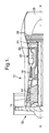
- Fig. 1 is a diagrammatic sectional view of a ducted fan gas turbine engine;
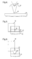
- Fig. 2 is a diagrammatic sectional view indicating a first embodiment of the invention;
- Fig. 3 is a diagrammatic sectional view indicating a second embodiment of the invention;
- Fig. 4 is a diagrammatic sectional view indicating a third embodiment of the invention;
- Fig. 5 is a diagrammatic sectional view indicating a fourth embodiment of the invention;
- Fig. 6 is a diagrammatic sectional view indicating a fifth embodiment of the invention; and
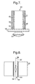
- Fig. 7 is a diagrammatic sectional view indicating a sixth embodiment of the invention.
-
- With reference to Fig. 1, a ducted fan gas turbine engine generally indicated at 10 comprises, in axial flow series, an
air intake 12, apropulsive fan 14, anintermediate pressure compressor 16, ahigh pressure compressor 18,combustion equipment 20, ahigh pressure turbine 22, anintermediate pressure turbine 24, alow pressure turbine 26 and anexhaust nozzle 28. - The
gas turbine engine 10 works in the conventional manner so that air entering theintake 12 is accelerated by thefan 14 to produce two air flows, a first air flow into theintermediate pressure compressor 16 and a second air flow which provides propulsive thrust. Theintermediate pressure compressor 16 compresses the air flow directed into it before delivering the air to thehigh pressure compressor 18 where further compression takes place. - The compressed air exhausted from the
high pressure compressor 18 is directed into thecombustion equipment 20 where it is mixed with fuel and the mixture combusted. The resultant hot combustion products then expand through and thereby drive the high, intermediate andlow pressure turbines nozzle 28 to provide additional propulsive thrust. The high, intermediate andlow pressure turbines intermediate pressure compressors fan 14 by suitable interconnecting shafts. - The aerofoil sections of the compressor and turbine blades and vanes are susceptible to damage as discussed previously. However, the likelihood of such damage occurring, or if it does occur leading to blade failure due to fatigue effects, may be minimised by surface treatment of the blades, for example by peening. This imparts to the surface region a residual compressive stress which reduces the effects of the tensile stresses applied to the surface by external loads.
- According to one aspect of the invention, the aerofoil sections are treated by electric spark processing. Electric spark processing uses an electrical discharge or current to generate a shock wave which impacts the component to be treated. The shock wave induces residual compressive stresses within the component, thus producing the "peening" effect discussed above.
- Referring to Fig. 2 a
component 30 to be treated is placed in afluid medium 32, such as water or oil. Thecomponent 30 may be an aerofoil section of a compressor or fan blade, for example. Anelectrical discharge circuit 34, which in this example includes acapacitor 36, includes a pair ofelectrodes 38 positioned about 5 to 10 mm apart within the medium 32. - The
electrical discharge circuit 34 is able to generate a very rapid electrical discharge (for example, having an energy of over 40 J within a duration of under 30 ns). This causes aplasma 39 to be generated within the medium 32 leading toshock waves 33 which travel through the medium to thecomponent 30. When the shock waves hit asurface 40 of thecomponent 30, a compressive force of up to around 20 GPa is generated at the surface of the component, causing a significant compressive stress. - Referring to Fig. 3, the simple system of Fig. 2 may be modified in that the
electrodes 38 may be provided between thecomponent 30 and a restrainingmember 42. The restrainingmember 42 is fixed in place and includes aninner face 43 which forms a simple reflector for the shock waves. The restrainingmember 42 restricts movement of the medium 32 and hence increases the energy of the shock waves incident on thecomponent 30. - Referring to Fig. 4, in an alternative embodiment of the invention a
concave reflector 44 is positioned such that theelectrodes 38 are located between thereflector 44 and thecomponent 30. Thereflector 44 may be used to localise, spread or otherwise shape the shock waves. The shock waves may be shaped to give them a substantially uniform intensity to give a uniform peening action, or alternatively may be shaped to produce non-uniform pressures on the surface of the component to give characteristics which may be required for overlapping of application areas or for forming specific shapes. The example shown in Fig. 4 demonstrates a focusing application, the waves being focused towards anapplication point 45. - Referring to Fig. 5, in an alternative embodiment of the invention, a conducting
membrane 46 is placed in close or intimate contact with thesurface 40 of thecomponent 30 to be treated. Alternatively a conductive coating could be applied to the surface, although this would need to be removed after processing. The coating could consist of a sacrificial layer of the parent material, which could be machined off or otherwise removed after processing. The electrical discharge in this embodiment takes place between themembrane 46 and anelectrode 38 located close to the conductingmembrane 46. This allows the electrical discharge to be close to thesurface 40 without causing damage to it by direct spark impact. Any damage occurs to the conductingmembrane 46, which may be replaced. This method also allows more complex shapes to be processed without the need to very accurately control the gap between the electrodes and the surface in order to prevent discharge onto the surface. The technique could also be used inside cavities and holes. - Referring to Fig. 6, an alternative embodiment of the invention includes a focusing means in the form of a
solid member 48. Thesolid member 48 is located near to the component and in this embodiment is of a generally frusto conical shape. A sectional area of thesolid member 48 near to thecomponent 30 is smaller than a sectional area of thesolid member 48 remote from thecomponent 30. Shock waves travel faster within thesolid member 48 than within the medium 32 and are focused by the reducing sectional area of the solid member as the shock waves approach thecomponent 30. This increases the intensity of the shock wave as it impacts the component. Again, any spark damage occurs to themember 48, rather than thecomponent 30. - The component may be an aerofoil section of, for example, a compressor blade. Referring to Fig. 7, a
compressor blade 50 comprises anaerofoil section 52, aroot portion 54 and aplatform 56 connecting theroot portion 54 of theblade 50 to theaerofoil section 52. The aerofoil section includes aleading edge 58 and a trailingedge 60. - The leading and trailing
edges aerofoil section 52 are treated using electric spark processing as previously described. The blade includes a pressure side (facing out of the page in Fig. 7) and a suction side (facing into the page in Fig. 7). In a preferred method according to the invention, electric spark processing is used to provide a simultaneous peening of both the pressure side and the suction side of the leading or trailingedge areas 61 of Fig. 7. By processing both sides simultaneously, distortion of the blade is minimised. Progressive alternating treatment of either side could produce a similar effect. - Referring to Fig. 8, an
alternative component 30 includes anorifice 62, the inside walls of which are to be peened by electric spark processing. A tube orsleeve 64 is provided within theorifice 62 andelectrodes 38 are provided within thetube 64. Thetube 64 insulates the surfaces from the component from sparks, but allows the ultrasonic shock pulse to travel therethrough. - There is thus provided a method for prestressing or peening the surfaces of components, which allows for penetrations of up to 1 mm or more and associated induced compressive stresses of up to 500 to 600 MPa at the surface of the component. Deep compressive residual stresses may be provided in the edges of aerofoil sections. The stresses may be provided in a strip along the leading and trailing edges extending across the blade for up to about 20% of the chord width on both the pressure and suction sides of the blade. The regions of compressive stress tend to extend further into the components than is the case where conventional shot peening methods are used. This may be partly because the stresses induced by shot peening tend to the "three dimensional" extending outwardly from the small impact point of each shot. In contrast, in the method according to the invention, a shock wave hits the whole of an area of the surface of the component, providing a "two dimensional" pressure. The effect of this is to provide residual stresses deeper into the component.
- Various modifications may be made to the above described embodiments without departing from the scope of the invention. The methods of producing the current, and of directing and focusing the shock wave, may be modified. Many such methods are known and available. The method may be used to treat any component where prestressing is desirable, for example where shot peening is currently used. Such components may include, for example, the leading edges of propellers and impellers for ships, and parts of turbomachinery including pumps, turbo and superchargers and ship and boat propellors and impellors.
- Whilst endeavouring in the foregoing specification to draw attention to those features of the invention believed to be of particular importance it should be understood that the Applicant claims protection in respect of any patentable feature or combination of features hereinbefore referred to and/or shown in the drawings whether or not particular emphasis has been placed thereon.
Claims (25)
- A method of prestressing a material (30), characterised in that the method includes the step of using an electrical discharge or current to produce a pressure pulse (33) in the material (30) or in a medium (32) adjacent the material (30), the pressure pulse (33) impacting a surface of the material (30) to produce a region of compressive residual stress within the material (30).
- A method according to claim 1 characterised in that the electrical discharge or current generates a plasma (39) in the medium (32).
- A method according to claim 1 or claim 2 characterised in that the electrical discharge or current has an energy of at least 35 J and a duration of less than 40 ns.
- A method according to any preceding claim characterised in that the pressure pulse produces an impact pressure of at least 15 GPa on the surface of the material (30).
- A method according to any preceding claim characterised in that the electrical discharge or current is provided between electrodes (38).
- A method according to any preceding claim characterised in that the discharge takes place between the material (30) and a fixed means (42) for containing the pressure pulse (33).
- A method according to any preceding claim characterised in that the discharge takes place remotely from the surface of the material (30) and the method includes the step of directing the pressure pulse (33) towards the surface of the material (30).
- A method according to claim 7 characterised in that the method includes the step of providing focusing means in the form of a reflector (44).
- A method according to any preceding claim characterised in that the method including the step of concentrating the pressure pulse (33) as it approaches the surface of the material (30).
- A method according to claim 9 characterised in that the method includes the step of providing concentrating means (48) of a material through which the pressure pulse (33) travels faster than it does in the medium (32), a sectional area of the concentrating means (48) remote from the surface of the material (30) being greater than a sectional area of the concentrating means (48) adjacent the material (30).
- A method according to any of claims 1 to 6 characterised in that the pressure pulse (33) is produced by direct impact of the electrical discharge or current on the surface of the material (30).
- A method according to claim 11 characterised by the further inclusion of the step of removing a damaged, sacrificial layer from the surface of the material (30).
- A method according to any preceding claim characterised by the inclusion of the step of providing a conducting membrane (46) over a surface of the material (30) and providing the electrical discharge or the current through the conducting membrane (46).
- A method according to any preceding claim characterised in that the material (30) comprises part of an aerofoil section (52), which may form part of a compressor or turbine blade or vane.
- A method according to claim 14 characterised in that the pressure pulse (33) impacts at least one of a leading (58) and a trailing (60) edge of the aerofoil section (52).
- A method according to claim 15 characterised in that the method includes the steps of producing a pressure pulse (33) which impacts a suction side of the leading or trailing edge and producing a pressure pulse which impacts a pressure side of the leading or trailing edge, the respective pressure pulses (33) impacting substantially simultaneously.
- A method according to any preceding claim characterised in that the material includes an orifice (62), the inside surfaces of which are to be prestressed, and the method includes the step of providing electrodes (38) within the orifice (62).
- A method according to claim 17, characterised in that the method further includes the step of providing a tube (64) of a non-conductive material within the orifice (62), the electrodes (38) being contained within the tube (64).
- A material including a region of compressive residual stress produced by a method according to any of claims 1 to 18.
- A material according to claim 19 characterised in that the region of compressive stress is provided in an area which is particularly subject to fatigue damage, foreign object damage, cavitation damage or erosion damage.
- A material according to claim 19 or 20 characterised in that the material (30) has been repaired prior to the production of the region of compressive stress.
- A material according to any of claims 19 to 21, characterised in that the material (30) comprising an aerofoil section (52) of a compressor or turbine blade or vane for a gas turbine engine.
- A material according to claim 22 characterised in that the region of compressive residual stress is provided within at least one of the leading and trailing edges of the aerofoil section (52).
- A material according to claim 23 characterised in that a region of residual compressive stress is provided on both of a suction and pressure side of the leading or trailing edge of the aerofoil section (52).
- A material according to any of claims 19 to 24 characterised in that the region of compressive residual stress extends at least 1 mm into the material (30).
Applications Claiming Priority (2)
| Application Number | Priority Date | Filing Date | Title |
|---|---|---|---|
| GBGB0023296.7A GB0023296D0 (en) | 2000-09-22 | 2000-09-22 | Prestressing of components |
| GB0023296 | 2000-09-22 |
Publications (2)
| Publication Number | Publication Date |
|---|---|
| EP1191112A1 true EP1191112A1 (en) | 2002-03-27 |
| EP1191112B1 EP1191112B1 (en) | 2006-03-15 |
Family
ID=9899953
Family Applications (1)
| Application Number | Title | Priority Date | Filing Date |
|---|---|---|---|
| EP01307678A Expired - Lifetime EP1191112B1 (en) | 2000-09-22 | 2001-09-10 | Prestressing of components |
Country Status (4)
| Country | Link |
|---|---|
| US (1) | US6685429B2 (en) |
| EP (1) | EP1191112B1 (en) |
| DE (1) | DE60117938T2 (en) |
| GB (1) | GB0023296D0 (en) |
Cited By (5)
| Publication number | Priority date | Publication date | Assignee | Title |
|---|---|---|---|---|
| WO2008037949A1 (en) | 2006-09-27 | 2008-04-03 | Rolls-Royce Plc | Apparatus and method for electric spark peening of gas turbine components |
| WO2008037948A1 (en) | 2006-09-27 | 2008-04-03 | Rolls-Royce Plc | A method and an apparatus for prestressing components by electrical discharge |
| WO2011061001A1 (en) | 2009-11-17 | 2011-05-26 | Rolls-Royce Plc | A method and an apparatus for prestressing components by electrical discharge |
| US9015942B2 (en) | 2011-07-25 | 2015-04-28 | Rolls-Royce Plc | Method of treating an aerofoil |
| CN113416869A (en) * | 2021-07-05 | 2021-09-21 | 四川大学 | Heterogeneous cobalt-chromium alloy based on laser additive and electric pulse treatment and preparation method thereof |
Families Citing this family (9)
| Publication number | Priority date | Publication date | Assignee | Title |
|---|---|---|---|---|
| WO2007055864A2 (en) * | 2005-10-12 | 2007-05-18 | Surface Technology Holdings, Ltd | Improved integrally bladed rotating turbo machinery and method and apparatus for achieving the same |
| US20080241546A1 (en) * | 2007-03-30 | 2008-10-02 | General Electric Company | Machining features in laser shock peened regions |
| DE102009036342A1 (en) * | 2009-08-06 | 2011-02-10 | Mtu Aero Engines Gmbh | Method for solidifying a component region and component with a component region solidified in this way |
| US9511388B2 (en) * | 2012-12-21 | 2016-12-06 | United Technologies Corporation | Method and system for holding a combustor panel during coating process |
| US10301950B2 (en) * | 2013-03-15 | 2019-05-28 | United Technologies Corporation | Enhanced protection for aluminum fan blade via sacrificial layer |
| US10371050B2 (en) | 2014-12-23 | 2019-08-06 | Rolls-Royce Corporation | Gas turbine engine with rotor blade tip clearance flow control |
| CN110306035B (en) * | 2019-07-22 | 2023-11-07 | 南方科技大学 | A method and device for electric spark peening strengthening of material surface |
| US11181518B2 (en) | 2019-10-31 | 2021-11-23 | The Boeing Company | System and method for evaluating a bond |
| US11953471B2 (en) | 2020-12-15 | 2024-04-09 | The Boeing Company | Under water acoustics plasma generator |
Citations (5)
| Publication number | Priority date | Publication date | Assignee | Title |
|---|---|---|---|---|
| EP0035091A1 (en) * | 1980-01-25 | 1981-09-09 | SCHOELLER-BLECKMANN Gesellschaft m.b.H. | Process for producing tension-crack corrosion-resistant non magnetizable drill collars of austenitic steels, and apparatus for carrying out this process |
| DE4428791C1 (en) * | 1994-08-13 | 1996-02-01 | Mtu Muenchen Gmbh | Surface hardening process for metal objects using ultrasonic waves |
| EP0829553A1 (en) * | 1996-09-13 | 1998-03-18 | Fraunhofer-Gesellschaft Zur Förderung Der Angewandten Forschung E.V. | Method and apparatus for modifying surfaces of metallic workpieces by electrical discharges |
| EP0924306A2 (en) * | 1997-12-18 | 1999-06-23 | General Electric Company | Metallic article and a method of laser shock peening a metallic article |
| WO1999065636A1 (en) * | 1998-06-14 | 1999-12-23 | Pulsar Welding Ltd. | Inducing physical changes in metal objects |
Family Cites Families (9)
| Publication number | Priority date | Publication date | Assignee | Title |
|---|---|---|---|---|
| SU760716A1 (en) | 1978-08-14 | 1996-06-27 | Проектно-конструкторское бюро электрогидравлики АН УССР | Method of treating welded joints |
| CH655032A5 (en) * | 1982-06-30 | 1986-03-27 | Mitsubishi Electric Corp | ELECTRIC DISCHARGE MACHINE FOR ELECTRO-EROSION. |
| SU1155396A1 (en) | 1983-08-05 | 1985-05-15 | Pk Byuro Elektrogidravliki An | Method of working welded structures |
| US5037524A (en) * | 1987-07-28 | 1991-08-06 | Juvan Christian H A | Apparatus for treating liquids with high-intensity pressure waves |
| SU1615199A1 (en) | 1988-08-15 | 1990-12-23 | Липецкий политехнический институт | Method of treating textured steel |
| US5911891A (en) * | 1997-09-11 | 1999-06-15 | Lsp Technologies, Inc. | Laser shock peening with tailored multiple laser beams |
| US5932120A (en) * | 1997-12-18 | 1999-08-03 | General Electric Company | Laser shock peening using low energy laser |
| US6159619A (en) * | 1997-12-18 | 2000-12-12 | General Electric Company | Ripstop laser shock peening |
| GB2367028B (en) * | 2000-09-22 | 2004-06-09 | Rolls Royce Plc | Gas turbine engine rotor blades |
-
2000
- 2000-09-22 GB GBGB0023296.7A patent/GB0023296D0/en not_active Ceased
-
2001
- 2001-09-10 DE DE60117938T patent/DE60117938T2/en not_active Expired - Lifetime
- 2001-09-10 EP EP01307678A patent/EP1191112B1/en not_active Expired - Lifetime
- 2001-09-12 US US09/949,978 patent/US6685429B2/en not_active Expired - Fee Related
Patent Citations (5)
| Publication number | Priority date | Publication date | Assignee | Title |
|---|---|---|---|---|
| EP0035091A1 (en) * | 1980-01-25 | 1981-09-09 | SCHOELLER-BLECKMANN Gesellschaft m.b.H. | Process for producing tension-crack corrosion-resistant non magnetizable drill collars of austenitic steels, and apparatus for carrying out this process |
| DE4428791C1 (en) * | 1994-08-13 | 1996-02-01 | Mtu Muenchen Gmbh | Surface hardening process for metal objects using ultrasonic waves |
| EP0829553A1 (en) * | 1996-09-13 | 1998-03-18 | Fraunhofer-Gesellschaft Zur Förderung Der Angewandten Forschung E.V. | Method and apparatus for modifying surfaces of metallic workpieces by electrical discharges |
| EP0924306A2 (en) * | 1997-12-18 | 1999-06-23 | General Electric Company | Metallic article and a method of laser shock peening a metallic article |
| WO1999065636A1 (en) * | 1998-06-14 | 1999-12-23 | Pulsar Welding Ltd. | Inducing physical changes in metal objects |
Cited By (8)
| Publication number | Priority date | Publication date | Assignee | Title |
|---|---|---|---|---|
| WO2008037949A1 (en) | 2006-09-27 | 2008-04-03 | Rolls-Royce Plc | Apparatus and method for electric spark peening of gas turbine components |
| WO2008037948A1 (en) | 2006-09-27 | 2008-04-03 | Rolls-Royce Plc | A method and an apparatus for prestressing components by electrical discharge |
| US8257050B2 (en) | 2006-09-27 | 2012-09-04 | Rolls-Royce Plc | Apparatus and method for electric spark peening of gas turbine components |
| US8316678B2 (en) | 2006-09-27 | 2012-11-27 | Rolls-Royce Plc | Method and an apparatus for prestressing components |
| WO2011061001A1 (en) | 2009-11-17 | 2011-05-26 | Rolls-Royce Plc | A method and an apparatus for prestressing components by electrical discharge |
| US9290825B2 (en) | 2009-11-17 | 2016-03-22 | Rolls-Royce Plc | Method and an apparatus for prestressing components by electrical discharge |
| US9015942B2 (en) | 2011-07-25 | 2015-04-28 | Rolls-Royce Plc | Method of treating an aerofoil |
| CN113416869A (en) * | 2021-07-05 | 2021-09-21 | 四川大学 | Heterogeneous cobalt-chromium alloy based on laser additive and electric pulse treatment and preparation method thereof |
Also Published As
| Publication number | Publication date |
|---|---|
| DE60117938D1 (en) | 2006-05-11 |
| DE60117938T2 (en) | 2006-08-17 |
| EP1191112B1 (en) | 2006-03-15 |
| GB0023296D0 (en) | 2000-11-08 |
| US20020037218A1 (en) | 2002-03-28 |
| US6685429B2 (en) | 2004-02-03 |
Similar Documents
| Publication | Publication Date | Title |
|---|---|---|
| US6517319B2 (en) | Gas turbine engine rotor blades | |
| US6685429B2 (en) | Prestressing of components | |
| JP4951292B2 (en) | Metal parts treated by compressing sublayers and methods for obtaining such parts | |
| EP1741796B1 (en) | Countering laser shock peening induced airfoil twist using shot peening | |
| US5591009A (en) | Laser shock peened gas turbine engine fan blade edges | |
| KR100423194B1 (en) | A technique to prevent or divert cracks | |
| EP0850321B1 (en) | Dry tape covered laser shock peening | |
| US5620307A (en) | Laser shock peened gas turbine engine blade tip | |
| EP1905852B1 (en) | Varying fluence as a function of thickness during laser shock peening | |
| EP1662092B1 (en) | Fatigue-resistant gas turbine airfoil and method therefor | |
| JP2002200562A (en) | Method of improving service life of rotor blade locking part | |
| EP0731184A1 (en) | Laser shock peened gas turbine engine compressor airfoil edges | |
| EP1175956A1 (en) | Metallic article with integral end band under compression and method for making | |
| EP1288318A1 (en) | Simultaneous offset dual sided laser shock peening using low energy laser beams | |
| US6341936B1 (en) | FOD inspection of laser shock peened gas turbine engine airfoils | |
| EP2540977B1 (en) | Method of improving fatigue strength in a fan blade and corresponding fan blade | |
| US7204677B2 (en) | Countering laser shock peening induced blade twist | |
| US20150185109A1 (en) | Methods for Testing Laser Shock Peening | |
| US20040074572A1 (en) | Method and device for hardening a metal component by plasma pulse technology | |
| US10570755B2 (en) | Fan blade root |
Legal Events
| Date | Code | Title | Description |
|---|---|---|---|
| PUAI | Public reference made under article 153(3) epc to a published international application that has entered the european phase |
Free format text: ORIGINAL CODE: 0009012 |
|
| AK | Designated contracting states |
Kind code of ref document: A1 Designated state(s): AT BE CH CY DE DK ES FI FR GB GR IE IT LI LU MC NL PT SE TR |
|
| AX | Request for extension of the european patent |
Free format text: AL;LT;LV;MK;RO;SI |
|
| 17P | Request for examination filed |
Effective date: 20020228 |
|
| AKX | Designation fees paid |
Free format text: DE FR GB |
|
| 17Q | First examination report despatched |
Effective date: 20041215 |
|
| GRAP | Despatch of communication of intention to grant a patent |
Free format text: ORIGINAL CODE: EPIDOSNIGR1 |
|
| GRAS | Grant fee paid |
Free format text: ORIGINAL CODE: EPIDOSNIGR3 |
|
| GRAA | (expected) grant |
Free format text: ORIGINAL CODE: 0009210 |
|
| AK | Designated contracting states |
Kind code of ref document: B1 Designated state(s): DE FR GB |
|
| REG | Reference to a national code |
Ref country code: GB Ref legal event code: FG4D |
|
| REF | Corresponds to: |
Ref document number: 60117938 Country of ref document: DE Date of ref document: 20060511 Kind code of ref document: P |
|
| ET | Fr: translation filed | ||
| PLBE | No opposition filed within time limit |
Free format text: ORIGINAL CODE: 0009261 |
|
| STAA | Information on the status of an ep patent application or granted ep patent |
Free format text: STATUS: NO OPPOSITION FILED WITHIN TIME LIMIT |
|
| 26N | No opposition filed |
Effective date: 20061218 |
|
| PGFP | Annual fee paid to national office [announced via postgrant information from national office to epo] |
Ref country code: GB Payment date: 20140929 Year of fee payment: 14 Ref country code: FR Payment date: 20140917 Year of fee payment: 14 |
|
| PGFP | Annual fee paid to national office [announced via postgrant information from national office to epo] |
Ref country code: DE Payment date: 20140929 Year of fee payment: 14 |
|
| REG | Reference to a national code |
Ref country code: DE Ref legal event code: R119 Ref document number: 60117938 Country of ref document: DE |
|
| GBPC | Gb: european patent ceased through non-payment of renewal fee |
Effective date: 20150910 |
|
| REG | Reference to a national code |
Ref country code: FR Ref legal event code: ST Effective date: 20160531 |
|
| PG25 | Lapsed in a contracting state [announced via postgrant information from national office to epo] |
Ref country code: DE Free format text: LAPSE BECAUSE OF NON-PAYMENT OF DUE FEES Effective date: 20160401 Ref country code: GB Free format text: LAPSE BECAUSE OF NON-PAYMENT OF DUE FEES Effective date: 20150910 |
|
| PG25 | Lapsed in a contracting state [announced via postgrant information from national office to epo] |
Ref country code: FR Free format text: LAPSE BECAUSE OF NON-PAYMENT OF DUE FEES Effective date: 20150930 |