EP1190992A2 - Method of producing an optical fiber preform using deposition burners - Google Patents
Method of producing an optical fiber preform using deposition burners Download PDFInfo
- Publication number
- EP1190992A2 EP1190992A2 EP01122515A EP01122515A EP1190992A2 EP 1190992 A2 EP1190992 A2 EP 1190992A2 EP 01122515 A EP01122515 A EP 01122515A EP 01122515 A EP01122515 A EP 01122515A EP 1190992 A2 EP1190992 A2 EP 1190992A2
- Authority
- EP
- European Patent Office
- Prior art keywords
- optical fiber
- turns
- starting rod
- fiber preform
- producing
- Prior art date
- Legal status (The legal status is an assumption and is not a legal conclusion. Google has not performed a legal analysis and makes no representation as to the accuracy of the status listed.)
- Withdrawn
Links
Images

Classifications
-
- G—PHYSICS
- G02—OPTICS
- G02B—OPTICAL ELEMENTS, SYSTEMS OR APPARATUS
- G02B6/00—Light guides; Structural details of arrangements comprising light guides and other optical elements, e.g. couplings
-
- C—CHEMISTRY; METALLURGY
- C03—GLASS; MINERAL OR SLAG WOOL
- C03B—MANUFACTURE, SHAPING, OR SUPPLEMENTARY PROCESSES
- C03B37/00—Manufacture or treatment of flakes, fibres, or filaments from softened glass, minerals, or slags
- C03B37/01—Manufacture of glass fibres or filaments
- C03B37/012—Manufacture of preforms for drawing fibres or filaments
- C03B37/014—Manufacture of preforms for drawing fibres or filaments made entirely or partially by chemical means, e.g. vapour phase deposition of bulk porous glass either by outside vapour deposition [OVD], or by outside vapour phase oxidation [OVPO] or by vapour axial deposition [VAD]
- C03B37/01486—Means for supporting, rotating or translating the preforms being formed, e.g. lathes
-
- C—CHEMISTRY; METALLURGY
- C03—GLASS; MINERAL OR SLAG WOOL
- C03B—MANUFACTURE, SHAPING, OR SUPPLEMENTARY PROCESSES
- C03B37/00—Manufacture or treatment of flakes, fibres, or filaments from softened glass, minerals, or slags
- C03B37/01—Manufacture of glass fibres or filaments
- C03B37/012—Manufacture of preforms for drawing fibres or filaments
- C03B37/014—Manufacture of preforms for drawing fibres or filaments made entirely or partially by chemical means, e.g. vapour phase deposition of bulk porous glass either by outside vapour deposition [OVD], or by outside vapour phase oxidation [OVPO] or by vapour axial deposition [VAD]
- C03B37/01413—Reactant delivery systems
- C03B37/0142—Reactant deposition burners
-
- C—CHEMISTRY; METALLURGY
- C03—GLASS; MINERAL OR SLAG WOOL
- C03B—MANUFACTURE, SHAPING, OR SUPPLEMENTARY PROCESSES
- C03B2207/00—Glass deposition burners
- C03B2207/50—Multiple burner arrangements
- C03B2207/52—Linear array of like burners
-
- C—CHEMISTRY; METALLURGY
- C03—GLASS; MINERAL OR SLAG WOOL
- C03B—MANUFACTURE, SHAPING, OR SUPPLEMENTARY PROCESSES
- C03B2207/00—Glass deposition burners
- C03B2207/60—Relationship between burner and deposit, e.g. position
- C03B2207/66—Relative motion
-
- C—CHEMISTRY; METALLURGY
- C03—GLASS; MINERAL OR SLAG WOOL
- C03B—MANUFACTURE, SHAPING, OR SUPPLEMENTARY PROCESSES
- C03B2207/00—Glass deposition burners
- C03B2207/70—Control measures
-
- Y—GENERAL TAGGING OF NEW TECHNOLOGICAL DEVELOPMENTS; GENERAL TAGGING OF CROSS-SECTIONAL TECHNOLOGIES SPANNING OVER SEVERAL SECTIONS OF THE IPC; TECHNICAL SUBJECTS COVERED BY FORMER USPC CROSS-REFERENCE ART COLLECTIONS [XRACs] AND DIGESTS
- Y02—TECHNOLOGIES OR APPLICATIONS FOR MITIGATION OR ADAPTATION AGAINST CLIMATE CHANGE
- Y02P—CLIMATE CHANGE MITIGATION TECHNOLOGIES IN THE PRODUCTION OR PROCESSING OF GOODS
- Y02P40/00—Technologies relating to the processing of minerals
- Y02P40/50—Glass production, e.g. reusing waste heat during processing or shaping
- Y02P40/57—Improving the yield, e-g- reduction of reject rates
Definitions
- the present invention relates to a method of producing an optical fiber preform by an OVD (Outside Vapor Deposition) method. Specifically, the present invention relates to the method of producing the optical fiber preform including a soot deposition process by which the outer diameter fluctuation of the optical fiber perform is slight in a longitudinal direction, and the deposition efficiency of the soot (glass particles) is high, and it is possible to adjust a ratio of a diameter of a starting rod portion of the optical fiber perform to a diameter of the optical fiber preform.
- OVD Outside Vapor Deposition
- a method for producing a large size optical fiber preform at the high speed there is a method that a plurality of glass particles synthesizing burners are arranged at a predetermined interval opposite to a starting rod, and glass particles (soot) are deposited on the starting rod surface in layer form (multi-layers soot deposition) while the rotating starting rod and row of the burners are relatively reciprocally moved.
- the relative movement of burners and the starting rod from one end to the other end in the reciprocal movement is called "traverse".
- it is important that the outer diameter fluctuation in the longitudinal direction of the glass particle deposit (soot body) is the slightest, and many kinds of methods for that are proposed.
- one of factors of the outer diameter fluctuation of the soot body is that a reciprocating speed of the burners and/or the starting rod (that is, relative reciprocating speed of the burners and the starting rod) becomes zero at a turning back position of the traverse (hereinafter, called turning back portion).
- a reciprocating speed of the burners and/or the starting rod that is, relative reciprocating speed of the burners and the starting rod
- turns back portion a turning back position of the traverse
- the fluctuation at the turning back portion in which actually soot deposition time is extended, or the fluctuation of the degree of toughing of the burner flame onto the soot body, is distributed to the whole soot body, and the actual soot deposition time or atmosphere of the whole soot body is made averagely coincident with each other. Therefore, the deposition amount of the soot is uniform in the longitudinal direction, and the outer diameter fluctuation is reduced.
- a method to reduce the outer diameter fluctuation based on the method described in the above-mentioned Japanese Patent Unexamined Publication No. Hei. 3-228845, there is a method that the fluctuation of the outer diameter of the whole soot body is measured, and the additional soot deposition is conducted to a portion, in which the soot deposition amount is small, by an auxiliary soot deposition burner so as to reduce the fluctuation of the outer diameter (Japanese Patent Unexamined Publication No. Hei. 10-158025).
- the fluctuation of the outer diameter of the whole soot body is measured by a CCD camera which can monitor the whole soot body and a central information processor.
- the auxiliary soot deposition burner can independently traverse the whole soot body.
- the important factor in the characteristic of the optical fiber is that, after the overclad deposition, a ratio of the diameter of the starting rod portion to the diameter of the consolidated and vitrified body (hereinafter, called J ratio) can be accurately controlled to a target J ratio, and there is no fluctuation of the J ratio in the longitudinal direction (Incidentally, a consolidated and vitrified body is synonymous with an optical fiber preform).
- J ratio a ratio of the diameter of the starting rod portion to the diameter of the consolidated and vitrified body
- the fluctuation of the outer diameter in the longitudinal direction which has been studied in the prior art, means the J ratio fluctuation in the longitudinal direction.
- the J ratio is accurately controlled so that it is equal to the target J ratio.
- the soot deposition by a plurality of main burners is stopped, and then the soot deposition to portions at which the deposition amount is small is conducted by only the auxiliary soot deposition burner so that the target soot outer diameter is adjusted while the outer diameter fluctuation is reduced.
- the efficiency of the soot deposition is reduced (the necessary time for soot deposition is prolonged).
- a movement mechanism for traversing the auxiliary soot deposition burner over the whole range of the soot body is disposed in a vessel, or the movement mechanism is arranged outside the vessel.
- the movement mechanism is arranged outside the vessel, it is necessary to provide a hole for whole range traversing to insert the burner into the vessel.
- the impurities are mixed in the soot, and they cause voids at the time of consolidating and vitrifying the soot body into a transparent.
- a hole is provided in the vessel, a capability that voids are generated by the impurities mixing from the outside is increased. This is the reason why air inside the vessel is kept in the negative pressure so as not to go out to the outside, because the inside of the ressel is in the acid atmosphere, and thereby the outside air enters into the vessel and the dust of outside the vessel accompanied with it enters into the vessel.
- an object of the present invention is to provide a method of producing an optical fiber preform including a soot deposition process by which the fluctuation of the J ratio of the optical fiber preform is slight in the longitudinal direction, the minute J ratio adjustment is possible, and the generation of the void by the mixing of the impurities into the soot is reduced.
- an another object of the present invention is to provide a method of producing an optical fiber preform including a soot deposition process in which the CCD camera or auxiliary soot deposition burner and the movement mechanism accompanied with it, as in the above-mentioned Japanese Patent Unexamined Publication No. Hei. 10-158025, are not necessary and also the cost in the equipment is low.
- the soot is basically deposited spirally. Therefore, when the reciprocating speed is increased, the spiral pitch is increased, and the unevenness is easily generated (the top (convex) and bottom (concave) are conspicuous) on the surface of the soot. In order to prevent it, it is necessary that the rotating speedof the rod is increased. However, there is a limit for increasing the rotating speed, owing to the strength of rod or the deposited layers. Each kind of factors is related to each other, therefore, it was found that it is necessary that correlations thereof are well controlled.
- the present invention is based on the result of such the general considerations.
- the above-mentioned object of the present invention can be achieved by the following method (1) - (8).
- the production method of the optical fiber preform of the present invention is based on the method in which a plurality of glass particles synthesizing burners are arranged with a predetermined burner interval opposite to a rotating starting rod, the starting rod and the glass particles synthesizing burners are parallely and relatively reciprocally moved, a turning back position of the reciprocal movement is moved in a predetermined direction by each predetermined distance, and when the turning back position is moved by a predetermined interval, the turning back position is moved to the reversal direction.
- the glass particles synthesized by the burners are successively deposited on the surface of the starting rod, and then the obtained glass particle deposit is consolidated and vitrified.
- the burner interval may be uniform, and the movement distance of the turning back position for each reciprocal movement is one integer-th of the burner interval.
- Tolerance for the burner interval is the range of ⁇ 15 % from the setting value, (including the case where the interval is not uniform).
- Tolerance for the movement distance of the turning back position is the range from one integer-th to ⁇ 15 % of the setting value of the burner interval.
- Tolerance for the movement distance of the turning back position until the turning back position is moved to the reversal direction is the range of ⁇ 10 % from the setting value of the burner interval.
- the soot deposition process in the production method of the optical fiber preform of the present invention is based on a multi-layer soot deposition method.
- a starting rod 1 and a plurality of glass particles synthesizing burners 2 are arranged in a vessel 4 in such a manner that the burners 2 are arranged with a predetermined burner interval (L) opposite to the starting rod 1.
- the starting rod 1 and the row of the burner 2 is relatively reciprocally moved (in the drawing, an example in which the starting rod 1 is reciprocally moved up and down, is shown).
- the starting rod 1 is also rotating.
- a turning back position of the reciprocal movement is moved in a predetermined direction by each one integral-th of the burner interval.
- the turning back position is moved by the burner interval, the turning back position is moved in a reversal direction.
- the glass particles (soot) are deposited on the surface of the starting rod 1 in layer form, and the glass particle deposit (soot body) 3 is produced.
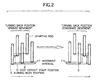
- a position of starting rod is shown left to right according to passage of time.
- the starting rod 1 moves from a soot deposition start position 5 upward, and turns back at a turning back position 6.
- the movement from the position 5 to position 6 is called a traverse.
- the rod 1 traverses downward, and turnback at a turn backposition 6' which is positioned upward from the soot deposition start position 5 by a movement interval 7 corresponding to one integer-th of the burner interval. That is, for each reciprocal movement, the turning back position of the reciprocal movement is moved to upward by each movement interval 7 corresponding to one integer-th of the burner interval.
- the turning back position When the turning back position is moved by the burner interval, as shown in the right side in the drawing, the turning back position is moved downward by each movement interval 7 corresponding to one integer-th of the burner interval.
- the movement of the burners to return to the soot deposition start position 5 is made one unit. This operation is repeated up to a predetermined J ratio.
- the number of turns of the one unit is the averaged number of turns.
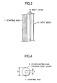
- the soot body 3 obtained in this manner, as shown in Fig. 3, has such a structure that the soot is deposited to form a soot layer 8 on the outer periphery of the starting rod 1.
- the J ratio is a ratio of the diameter of the starting rod to the diameter of consolidated and vitrified body obtained from a soot body in which the glass layer newly deposited by the soot deposition.
- the J ratio is defined by X/Y in Fig. 4.
- Y is the diameter of the starting rod portion
- X is the diameter of the preform which is obtained by consolidating and vitrifying the soot body formed by the soot deposition (jacketing) process.
- An actual J ratio is calculated on the basis of the measurement of the consolidated and vitrified body.
- a ratio of the diameter of the starting rod in the soot body to the diameter of the soot body (which called J ratio of soot body) is synonymous with J ratio of the preform.
- the method of the present invention is to provide the soot depositionmethod to conduct the accurate J ratio adjustment, and finding of solution of the newly generated problems therein.
- the method of present invention provides a setting method of the soot deposition completion time including: selecting the main factors which influence the J ratio adjustment; determining their correlations; and making a premise of the correlations.
- the J ratio fluctuation in the longitudinal direction can be improved in such a manner that the turning back position of the rod or burner is moved, and the soot deposition is completed in the integer times of the averaged number of turns.
- the soot deposition is completed when the J ratio of soot body becomes the target J ratio of soot body, in other words, ordinarily, the soot deposition is completed on the way of the averaged number of turns, and thereby J ratio fluctuation is generated in the longitudinal direction. Accordingly, the present inventors had an idea that the soot deposition amount per averaged number of turns is reduced whereby fine adjustment can be conducted..
- the reciprocating speed is increased, because the soot deposition time per one traverse is decreased, the J ratio adjustment becomes improved to some extent.
- the reciprocating speed is further increased, it was found that the outer diameter fluctuation is generated. That is, in the soot deposition process, while the burner or the rod is traversed, the soot deposition is conducted on the rotating starting rod. That is, the soot is deposited on the rod in such a manner that the spiral pattern is written.
- the reciprocating speed is low (60 - 200 mm/minute)
- the interval of the gap in which the soot of the spiral pattern is not deposited is very narrow, and the outer diameter fluctuation is not generated.
- the reciprocating speed is increased, the interval of the gap becomes very large, thereby the outer diameter fluctuation (the J ratio fluctuation in the longitudinal direction) is generated when the soot is deposited spirally.
- this method is not desirable because it causes that the effect of dispersing turning back points in the longitudinal direction for suppressing the J ratio fluctuation is decreased.
- Another method is that the reciprocating speed is increased to high speed, and the soot deposition amount per traverse is reduced. Even when the reciprocating speed is increased and the deposition amount of the soot is reduced, the deposition efficiency per time is not lowered.
- the present invention provides a soot deposition method by which the parameters are optimized, the J ratio fluctuation in the longitudinal direction is small, and the J ratio adjustment can be conducted.
- L when the burner interval L is estimated by tolerance of ⁇ 15 %, (that is, when the setting value of the burner interval is L 0 , 0.85 L 0 ⁇ L ⁇ 1.15 L 0 ), in the above expression of A, L may be replaced with L 0 .
- the value A exceeds the upper limit.
- the value A of the expression is larger than the upper limit because the v becomes small.
- the value A exceeds the upper limit also when the burner interval becomes large. In this case, it shows that the burner interval becomes large and the averaged number of turns is increased, thereby the J ratio adjustment becomes difficult.
- the value A exceeds the upper limit. In this case, it shows that the centrifugal force on the rod is increased, and there is a risk that the rod has a crack, which is not desirable.
- the value A when v becomes large, or r or L becomes small, the value A is lower than the lower limit. In other words, when the reciprocating speed is large (v becomes large), the value A is lower than the lower limit. This shows that the reciprocating speed becomes large and the spiral distance of the soot deposition is spread, thereby the J ratio in the longitudinal direction becomes difficult to suppress. When the burner interval L becomes small, the averaged number of turns is decreased. This shows that it is better for the characteristic of the optical fiber to decrease the reciprocating speed so as to make the spiral distance narrow and so as to increase the J ratio suppression capability in the longitudinal direction.
- the value A of the above expression is lower than the lower limit also when the axis rotating speed is decreased. This shows that the rotating speed is lowered, and thereby the J ratio fluctuation in the longitudinal direction becomes difficult to reduce.
- the J ratio fluctuation suppression in the longitudinal direction and the accurate J ratio adjustment can be conducted.
- the soot deposition method of the present invention the soot is spirally deposited.
- the relationship between the reciprocating speed v (mm/minute) and the axis rotating speed r is controlled so that the center line of the soot deposited spirally by one traverse is not overlapped with the center line of the soot deposited at the preceding traverse.
- the relationship between the reciprocating speed v and the axis rotating speed r in such the case differs due to the burner interval or the traverse distance between the turningback points.
- the center line is a line on which an apex of a cone made of deposited soot from one burner is moved.
- the rod reciprocating speed v is set faster than the prior art.
- the rod reciprocating speed v (mm/minute) is in the range of 500 ⁇ v ⁇ 3000, more preferably 700 ⁇ v ⁇ 2000.
- the lower limit value is the minimum rod reciprocating speed necessary for conducting the J ratio adjustment.
- the upper limit value is the speed of the limit by which the J ratio fluctuation in the longitudinal direction can be in the level in which there is no problem for the optical fiber characteristic, by adjusting the rotating speed or burner interval.
- the burner interval L (mm) is in the range of 150 ⁇ L ⁇ 350, and more preferably, 200 ⁇ L ⁇ 300. For L 0 , it is the same.
- the reciprocating speed is increased, and the rotating speed is increased.
- the increase of the rotating speed results in an increase of the centrifugal force on the rod, the increase of the rotating speed has also the limit. Therefore, when the soot weight of the target J ratio is M (kg) and the outer diameter of the starting rod is b (mm), it is preferable that the axis rotating speed r (rpm) is in the range of 27 ⁇ 10 x Log [(M x r)/b].
- This expression gives an index in which the durability of the starting rod is increased by increasing the starting rod diameter, or by decreasing the rotating speed when the target soot weight is increased, or an index in which the stress on the starting rod is decreased.
- the target weight M kg and the starting rod diameter b are determined by the target characteristic of the optical fiber, the upper limit is given by the rotating speed of the axis rotation.
- the soot deposition amount per averaged number of turns is reduced. Accordingly, when the number of turns at which the soot weight is closest to the weight of target J ratio and which is the integer times of the averaged number of turns, is made the soot deposition completion turn (at which the soot deposition process is completed), the J ratio adjustment can be conducted with the accuracy which can not be obtained in prior arts.
- the more accurate J ratio adjustment can be conducted by a method in which the reciprocating speed v (mm/minute) after B turns is adjusted so that the soot weight deposited during one traverse is (M - N) /C (kg), and the soot deposition is completed when the number of traverse turns is B +C, wherein the soot weight of the target J ratio is M (kg), an integer times of the averaged number of turns at which the soot weight is not more than M (kg) and closest to M (kg) is B turns, the soot weight at B turns is N (kg), and the averaged member of turns is C (times).
- An Apparatus in which 4 burners are arranged respectively with the interval of 150, 200, and 350 mm in the structure in Fig. 1, is used.
- the soot deposition in the multi-layers is conducted on the outer periphery of the starting rod with the outer diameter of 36 mm, and the effective portion length of 500 mm.
- the production test of the soot body of the outer diameter of 210 mm (the target J ratio is 3.0 times, the soot weight at the time is 15.5 kg) is carried out.
- the traverse method has a movement in which, after the rod is lowered by the burner interval, it is pulled up by the burner interval x 0.9; this operation is conducted 10 times until the rod is dislocated downward by the burner interval; after it is pulled up by the length of the burner interval x 1.1, it is lowered by the burner interval; and this operation is conducted repeatedly so that the rod is returned to the initial rod position (the number of turns up to this time is the averaged number of turns, and' in this case, 20 times) .
- the soot body is produced by changing the reciprocating speed and the rotating speed of the starting rod (axis rotating speed).
- the change of the J ratio rate (the rate of the difference of the obtained J ratio and the target J ratio to the target J ratio), is investigated.
- the soot deposition is completed at the time point at which the soot weight is closest to the weight of the target J ratio at the number of turns which is the integer times of the averaged number of turns.
- the deaeration may be conducted in the furnace which is maintained at the high temperature and the vitrification is conducted to obtain the transparent optical fiber preform.
- the J ratio rate is not larger than ⁇ 7 %, which is an aim at which a fine quality preform is obtained. Further, it is found that, when the value of A is in the range of 10 - 30, the J ratio rate can be suppressed to not larger than ⁇ 4 %.
- the soot deposition is conducted at the rod reciprocating speed of 703 mm/minute and the axis rotating speed of 30 and 50 rpm. Then the gas is taken away from soot and the vitrification is conducted to obtain the transparent optical fiber preform.
- the gap of the average J ratio in the longitudinal direction from the target J ratio is 0.2 times at 30 rpm (J ratio rate 6.7 %), and 0.1 times at 50 rpm (J ratio rate 3.3 %).
- J ratio fluctuation in the longitudinal direction is 3.5 % at 30 rpm, and 2 % at 50 rpm.
- the soot deposition is conducted at the rod reciprocating speed of 1503 mm/minute and the axis rotating speed of 90 rpm. After that, the deaeration and vitrification are conducted to obtain the transparent optical fiber preform. Because the reciprocating speed is high, and the soot deposition amount per the averaged number of turns is small, the J ratio adjustment becomes easy.
- the gap of the average J ratio in the longitudinal direction from the target J ratio in the optical fiber preform is 0. 11 times (J ratio rate 3.7 %).
- the J ratio fluctuation in the longitudinal . direction is 3 % by increasing the reciprocating speed.
- the soot deposition is conducted at the rod reciprocating speed of 800 mm/minute and the axis rotating speed of 40 rpm. After that, the deaeration and vitrification are conducted to obtain the transparent optical fiber preform.
- the center line of the soot spirally deposited by one traverse is almost over lapped with the center line of the soot deposited at the preceding traverse, thereby the J ratio fluctuation becomes large.
- the gap of the average J ratio in the longitudinal direction from the target J ratio is 0.17 times (J ratio rate 5.7 %), and the J ratio fluctuation in the longitudinal direction is 3.7 %.
- the soot deposition is conducted at the rod reciprocating speed of 63 mm/minute, and the axis rotating speed of 30 rpm. After that, the deaeration and vitrification are conducted to obtain the transparent optical fiber preform. Because the reciprocating speed is low, and the soot gap amount per averaged number of turns is large, the J ratio control is difficult.
- the gap of the average J ratio in the longitudinal direction from the target J ratio, in the optical fiber preform is 0.5 times (J ratio rate 16.7 %) and the J ratio fluctuation in the longitudinal direction is 6 %.
- the rod reciprocating speed is to 1503 mm/minute
- the same operation as Example 1 is carried out.
- the reciprocating speed is increased, the rotating speed is remained small, and thereby the spiral outer diameter fluctuation is increased.
- the gap of the average J ratio in the longitudinal direction in the optical fiber preform after the deaeration and vitrification, from the target J ratio is 0.25 times (J ratio rate 8.3 %).
- the J ratio fluctuation in the longitudinal direction is 10.0 %.
- the soot deposition is conducted when the rod reciprocating speed is 803 mm/minute, and the axis rotating speed is 600 rpm, and the target J ratio is 3.8.
- the number of turns at which the soot weight is closest to the soot weight (20. 5 kg) which is the target J ratio is the number of turns at which the number of traverse turns is 500 times (25 times of.the averaged number of turns), and the soot weight at that time is 19.8 kg.
- the gap of the average J ratio in the longitudinal direction from the target J ratio is 0.12 times (J ratio rate 3.2 %).
- the J ratio fluctuation in the longitudinal direction at this time is 2.5 %.
- the soot deposition is conducted up to the number of traverse turns at which the soot weight becomes a weight, which is not larger than 20.5 kg (defined as M) which is the soot weight as the target J ratio, and is closest to M.
- the soot weight at the time is 19.8 kg (defined as N) .
- the soot deposition of 20 turns corresponding to one averaged number of turns is continued, and the soot deposition is completed.
- the soot deposition is conducted under the same condition as Example 3.
- the change of the J ratio is investigated.
- the J ratio fluctuation in the longitudinal direction is respectively 3.2 %, 4.5 %, 7.2 %, and 11.3 %.
- the influence due to the difference of the burner interval of about 10 % is moderated by the spread of the burner, and it is found that so much influence in the J ratio fluctuation in the longitudinal direction does not appear.
- the tolerance is exceeded, because the outer diameter fluctuation is further increased, it is desirable that the fluctuation of the burner interval is within 15 %. More preferably, it is within 10 %.
- the soot deposition is conducted in the same condition as Example 3.
- the soot deposition is conducted in the same condition as Example 3.
- the soot deposition is conducted in the same condition as Example 3.
- these examples are examples in which the total movement distance until the movement direction of the turning back position is reversed, is respectively dislocated to -20 %, -10 %, 0 %, + 10 %, and + 20 % to the burner interval.
- the J ratio fluctuation in the longitudinal direction after the deaeration and vitrification is almost the same in the 3 examples, and respectively 12 %, 5 %, 3 %, 4 % and 11 %. It is found that when the gap of the movement distance until the movement direction of the turning back position is reversed is in the range of about ⁇ 15 %, it is in a tolerance. Desirably, it is within 10 %.
- the soot deposition is conducted in the same condition as Example 3.
- the J ratio fluctuation in the longitudinal direction after the deaeration and vitrification is respectively 4.3 %, 7.2 %, and 11.4%. Because the fluctuation is suddenly increased as the gap amount is increased, it can be.seen that the gap of the movement distance of the turning whack position for each reciprocal movement is desirably within ⁇ 15 %. More desirably, it is within 10 %.
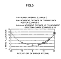
- Fig. 5 The results of examples 7 - 10 are collected and shown in Fig. 5.
- the axis of ordinate shows the J ratio fluctuation.
- the axis of abscissa shows the rate of the gap from the setting value of the burner interval, the gap from one integer-th of the burner interval (or its setting value) of the movement distance of the turning back position for each reciprocal movement, and the gap from the burner interval (or its setting value) of the movement distance until the movement direction of the turning back position is reversed.
- Fig. 5 the axis of ordinate shows the J ratio fluctuation.
- the axis of abscissa shows the rate of the gap from the setting value of the burner interval, the gap from one integer-th of the burner interval (or its setting value) of the movement distance of the turning back position for each reciprocal movement, and the gap from the burner interval (or its setting value) of the movement distance until the movement direction of the turning back position is reversed.
- ⁇ expresses the gap of the burner interval (Example 7)
- ⁇ is the gap of the movement distance of the turning back position for each reciprocal movement (Example 9)
- ⁇ and ⁇ express the gap of the movement distance until the movement direction of the turning back position is reversed '(Examples 8 and 10).
Landscapes
- Chemical & Material Sciences (AREA)
- Engineering & Computer Science (AREA)
- Geochemistry & Mineralogy (AREA)
- Life Sciences & Earth Sciences (AREA)
- General Chemical & Material Sciences (AREA)
- General Life Sciences & Earth Sciences (AREA)
- Chemical Kinetics & Catalysis (AREA)
- Manufacturing & Machinery (AREA)
- Materials Engineering (AREA)
- Organic Chemistry (AREA)
- Physics & Mathematics (AREA)
- General Physics & Mathematics (AREA)
- Optics & Photonics (AREA)
- Manufacture, Treatment Of Glass Fibers (AREA)
- Glass Melting And Manufacturing (AREA)
Abstract
Description


Claims (16)
- A method of producing an optical fiber preform comprising:preparing a plurality of burners arranged with a burner interval of 0.85 L0 - 1.15 L0 opposite to a rotating starting rod;moving parallely and relatively reciprocally the starting rod and the burners while a turning back position of the reciprocal movement is moved in a predetermined direction by a predetermined distance for each movement, and when the turning back position is moved by 0.85 L0 - 1.15. L0, the turning back position is moved to a reversal direction by the predetermined distance for each movement, so that glass particles synthesized by the burners are successively deposited on a surface of the starting rod; andconsolidating and vitrifying the obtained glass particles deposit, wherein a relative reciprocating speed of the starting rod and burners v (mm/minute), an axis rotating speed of the starting rod r (rpm), and a burner interval setting value L0 (mm) are set so that a value A expressed by an expression A = (r/v) x L0 is in the range 40 ≧ A ≧ 8.
- A method of producing the optical fiber preform comprising:wherein a relative reciprocating speed of the starting rod and burners v (mm/minute), an axis rotating speed of the starting rod r (rpm), and a burner interval L (mm) are set so that a value A expressed by the expression A = (r/v) x L is in a range 40 ≧ A ≧ 8.preparing a plurality of burners arranged with a predetermined burner interval opposite to a rotating starting rod;moving parallely and relatively reciprocally the starting rod and the burners, while a turning back position of the reciprocal movement is moved in a predetermined direction by each one integer-th of the burner interval for each movement, and when the turning back position is moved by the burner interval, the turning back position is moved to a reversal direction by the each one integer-th of the burner interval for each movement, so that glass particles synthesized by the burners are successively deposited on a surface of the starting rod; andconsolidating and vitrifying the obtained glass particles deposit,
- The method of producing an optical fiber preform according to Claim 1, wherein the relationship between the relative reciprocating speed v (mm/minute) and the axis rotating speed r is controlled so that a center line of the glass particles spirally deposited at one traverse is not overlapped with a center line of the glass particles deposited at the preceding traverse.
- The method of producing an optical fiber preform according to Claim 2, wherein the relationship between the relative reciprocating speed v (mm/minute) and the axis rotating speed r is controlled so that a center line of the glass particles spirally deposited at one traverse is not overlapped with a center line of the glass particles deposited at the preceding traverse.
- The method of producing an optical fiber preform according to Claim 1, wherein the relative reciprocating speed v (mm/minute) is in the range of 500 ≦ v ≦ 3000.
- The method of producing an optical fiber preform according to Claim 2, wherein the relative reciprocating speed v (mm/minute) is in the range of 500 ≦ v ≦ 3000.
- The method of producing an optical fiber preform according to Claim 1, wherein the burner interval setting value L0 (mm) is in the range of 150 mm ≦ L0 ≦ 350 mm.
- The method of producing an optical fiber preform according to Claim 2, wherein the burner interval L (mm) is in the range of 150 mm ≦ L ≦ 350 mm.
- The method of producing an optical fiber preform according to Claim 1, wherein the axis rotating speed r (rpm) is in the range of 27 ≧ 10 x Log [(M x r)/b], wherein a glass particle weight of a target ratio of a diameter of the starting rod portion of the optical fiber perform to a diameter of the optical fiber preform is M (kg), and an outer diameter of the starting rod is b (mm).
- The method of producing an optical fiber preform according to Claim 2, wherein the axis rotating speed r (rpm) is in the range of 27 ≧ 10 x Log [(M x r)/b], wherein a glass particle weight of a target ratio of a diameter of the starting rod portion of the optical fiber perform to a diameter of the' optical fiber preform is M (kg), and an outer diameter of the starting rod is b (mm).
- The method of producing an optical fiber preform according to Claim 1, wherein the glass particles deposition is stopped at the time when the number of turns reaches an integer times of the averaged number of turns at which a glass particle weight becomes the closest for a weight of a target ratio of a diameter of the starting rod portion of the optical fiber perform to a diameter of the optical fiber perform.
- The method of producing an optical fiber preform according to Claim 2, wherein the glass particles deposition is stopped at the time when the number of turns reaches an integer times of the averaged number of turns at which a glass particle weight becomes the closest for a weight of a target ratio of a diameter of the starting rod portion of the optical fiber perform to a diameter of the optical fiber perform.
- The method of producing an optical fiber preform according to Claim 1, wherein the relative reciprocating speed v (mm/minute) after B turns is adjusted so that a glass particle weight deposited during one traverse is (M - N)/C (kg), and when the number of turns is B+C, deposition of the glass particles is stopped, wherein a glass particle weight of a target ratio. of a diameter of a starting rod portion of the optical fiber perform to a diameter of the optical fiber perform is M (kg), and an integer times of the averaged number of turns at which a glass particle weight is not larger than M (kg) and closest to M (kg) is B turns, the glass particle weight at the B turns is N (kg), and the averaged number of turns is C times.
- The method of producing an optical fiber preform according to Claim 2, wherein the relative reciprocating speed v (mm/minute) after B turns is adjusted so that a glass particle weight deposited during one traverse is (M - N)/C (kg), and when the number of turns is B + C, deposition of the glass particles is stopped, wherein a glass particle weight of a target ratio of a diameter of a starting rod portion of the optical fiber perform to a diameter of the optical fiber perform is M (kg), and an integer times of the averaged number of turns at which a glass particle weight is not larger than M (kg) and closest to M (kg) is B turns, the glass particle weight at the B turns is N (kg), and the averaged number of turns is C times.
- The method of producing an optical fiber preform according to Claim 1, wherein the parameters are set so that the value A is in the range 30 ≧ A ≧ 10.
- The method of producing an optical fiber preform according to Claim 2, wherein the parameters are set so that the value A is in a range 30 ≧ A ≧ 10.
Applications Claiming Priority (4)
| Application Number | Priority Date | Filing Date | Title |
|---|---|---|---|
| JP2000287071 | 2000-09-21 | ||
| JP2000287071 | 2000-09-21 | ||
| JP2001236247 | 2001-08-03 | ||
| JP2001236247A JP3521891B2 (en) | 2000-09-21 | 2001-08-03 | Manufacturing method of optical fiber preform |
Publications (2)
| Publication Number | Publication Date |
|---|---|
| EP1190992A2 true EP1190992A2 (en) | 2002-03-27 |
| EP1190992A3 EP1190992A3 (en) | 2004-04-07 |
Family
ID=26600428
Family Applications (1)
| Application Number | Title | Priority Date | Filing Date |
|---|---|---|---|
| EP01122515A Withdrawn EP1190992A3 (en) | 2000-09-21 | 2001-09-21 | Method of producing an optical fiber preform using deposition burners |
Country Status (7)
| Country | Link |
|---|---|
| US (1) | US6895783B2 (en) |
| EP (1) | EP1190992A3 (en) |
| JP (1) | JP3521891B2 (en) |
| KR (1) | KR100595356B1 (en) |
| CN (1) | CN1318333C (en) |
| AU (1) | AU778586B2 (en) |
| CA (1) | CA2357593A1 (en) |
Cited By (2)
| Publication number | Priority date | Publication date | Assignee | Title |
|---|---|---|---|---|
| EP1496021A4 (en) * | 2002-04-18 | 2011-04-27 | Sumitomo Electric Industries | METHOD FOR MANUFACTURING A BODY OVERLAPPED WITH GLASS PARTICLES |
| EP4282839A4 (en) * | 2021-01-20 | 2024-12-25 | Furukawa Electric Co., Ltd. | DEVICE AND METHOD FOR MANUFACTURING OPTICAL FIBER PREFORM |
Families Citing this family (18)
| Publication number | Priority date | Publication date | Assignee | Title |
|---|---|---|---|---|
| KR100496449B1 (en) * | 2002-06-28 | 2005-06-20 | 엘에스전선 주식회사 | Outside vapor deposition apparatus for making optical fiber preform and method of making optical fiber preform using the same |
| JP2006199526A (en) * | 2005-01-19 | 2006-08-03 | Shin Etsu Chem Co Ltd | Optical fiber preform manufacturing method |
| US20070174731A1 (en) * | 2005-12-30 | 2007-07-26 | Tilmann Haeberle | Contextual enterprise software support tools |
| JP4690979B2 (en) * | 2006-09-13 | 2011-06-01 | 古河電気工業株式会社 | Optical fiber preform manufacturing method |
| US12370352B2 (en) | 2007-06-28 | 2025-07-29 | Cydex Pharmaceuticals, Inc. | Nasal and ophthalmic delivery of aqueous corticosteroid solutions |
| US8625910B2 (en) * | 2011-02-25 | 2014-01-07 | Adobe Systems Incorporated | Compression of image data |
| JP5799666B2 (en) * | 2011-08-25 | 2015-10-28 | 住友電気工業株式会社 | Method for producing glass particulate deposit |
| JP5528489B2 (en) * | 2012-02-09 | 2014-06-25 | 信越化学工業株式会社 | Method for sintering porous glass base material |
| CN103771696A (en) * | 2012-10-18 | 2014-05-07 | 浙江富通光纤技术有限公司 | Method and apparatus for manufacturing optical fiber perform extramural cladding |
| JP6245648B2 (en) * | 2014-06-16 | 2017-12-13 | 信越化学工業株式会社 | Optical fiber preform manufacturing method |
| CN104129915A (en) * | 2014-08-18 | 2014-11-05 | 苏州新协力环保科技有限公司 | Novel manufacturing method of optical fiber performs |
| US10464838B2 (en) * | 2015-01-13 | 2019-11-05 | Asi/Silica Machinery, Llc | Enhanced particle deposition system and method |
| JP6097892B2 (en) * | 2015-03-31 | 2017-03-15 | 古河電気工業株式会社 | Method for producing porous glass preform for optical fiber |
| CN111051259A (en) * | 2017-08-29 | 2020-04-21 | 住友电气工业株式会社 | Method for producing glass fine particle deposit, method for producing glass base material, and glass base material |
| CN108558197A (en) * | 2018-05-25 | 2018-09-21 | 成都富通光通信技术有限公司 | A kind of more blowtorch longitudinal directions deposition method preparing loose media |
| JP7555208B2 (en) | 2020-07-15 | 2024-09-24 | 信越石英株式会社 | Large hollow porous quartz glass base material and its manufacturing method |
| CN113248133B (en) * | 2021-05-31 | 2021-09-17 | 中天科技精密材料有限公司 | Optical fiber preform manufacturing equipment and manufacturing method of optical fiber preform using same |
| EP4428106A1 (en) | 2023-03-07 | 2024-09-11 | Heraeus Quarzglas GmbH & Co. KG | Drive synchronisation for a soot deposition machine for avoiding structural formation in deposition processes |
Family Cites Families (10)
| Publication number | Priority date | Publication date | Assignee | Title |
|---|---|---|---|---|
| DE3304721A1 (en) * | 1983-02-11 | 1984-08-16 | Licentia Patent-Verwaltungs-Gmbh, 6000 Frankfurt | METHOD FOR PRODUCING A PREFORM FOR LIGHTWAVE GUIDES |
| JP2612949B2 (en) * | 1990-02-01 | 1997-05-21 | 信越化学工業株式会社 | Manufacturing method of optical fiber preform base material |
| JP2622182B2 (en) | 1990-03-29 | 1997-06-18 | 信越化学工業株式会社 | Manufacturing method of optical fiber preform base material |
| US5211732A (en) * | 1990-09-20 | 1993-05-18 | Corning Incorporated | Method for forming a porous glass preform |
| US5116400A (en) | 1990-09-20 | 1992-05-26 | Corning Incorporated | Apparatus for forming a porous glass preform |
| JPH0725637A (en) | 1993-07-09 | 1995-01-27 | Furukawa Electric Co Ltd:The | Method for manufacturing porous glass preform for optical fiber |
| DE19628958C2 (en) * | 1996-07-18 | 2000-02-24 | Heraeus Quarzglas | Process for the production of quartz glass bodies |
| JP3131162B2 (en) * | 1996-11-27 | 2001-01-31 | 信越化学工業株式会社 | Manufacturing method of optical fiber preform |
| DE60019029T2 (en) * | 1999-07-02 | 2006-02-16 | Shin-Etsu Chemical Co., Ltd. | Method and apparatus for producing a glass optical fiber preform by the external deposition method |
| US6553790B1 (en) * | 2000-05-09 | 2003-04-29 | Fitel Usa Corp. | Process for fabricating optical fiber involving tuning of core diameter profile |
-
2001
- 2001-08-03 JP JP2001236247A patent/JP3521891B2/en not_active Expired - Fee Related
- 2001-09-20 CA CA002357593A patent/CA2357593A1/en not_active Abandoned
- 2001-09-21 KR KR1020010058706A patent/KR100595356B1/en not_active Expired - Fee Related
- 2001-09-21 EP EP01122515A patent/EP1190992A3/en not_active Withdrawn
- 2001-09-21 AU AU75557/01A patent/AU778586B2/en not_active Ceased
- 2001-09-21 CN CNB01140728XA patent/CN1318333C/en not_active Expired - Lifetime
- 2001-09-21 US US09/956,867 patent/US6895783B2/en not_active Expired - Lifetime
Cited By (2)
| Publication number | Priority date | Publication date | Assignee | Title |
|---|---|---|---|---|
| EP1496021A4 (en) * | 2002-04-18 | 2011-04-27 | Sumitomo Electric Industries | METHOD FOR MANUFACTURING A BODY OVERLAPPED WITH GLASS PARTICLES |
| EP4282839A4 (en) * | 2021-01-20 | 2024-12-25 | Furukawa Electric Co., Ltd. | DEVICE AND METHOD FOR MANUFACTURING OPTICAL FIBER PREFORM |
Also Published As
| Publication number | Publication date |
|---|---|
| JP2002167228A (en) | 2002-06-11 |
| US6895783B2 (en) | 2005-05-24 |
| KR100595356B1 (en) | 2006-07-03 |
| KR20020023159A (en) | 2002-03-28 |
| JP3521891B2 (en) | 2004-04-26 |
| US20020081377A1 (en) | 2002-06-27 |
| CN1344694A (en) | 2002-04-17 |
| AU778586B2 (en) | 2004-12-09 |
| AU7555701A (en) | 2002-03-28 |
| EP1190992A3 (en) | 2004-04-07 |
| CN1318333C (en) | 2007-05-30 |
| CA2357593A1 (en) | 2002-03-21 |
Similar Documents
| Publication | Publication Date | Title |
|---|---|---|
| US6895783B2 (en) | Method of producing optical fiber preform | |
| US5958102A (en) | Apparatus and method for making an optical fiber preform using a correction pass | |
| EP0824090B1 (en) | Process for producing optical fiber preform | |
| EP0151438B1 (en) | Method for producing glass preform for optical fiber | |
| JP2612949B2 (en) | Manufacturing method of optical fiber preform base material | |
| EP1279646B1 (en) | Method and apparatus for producing a glass preform for optical fibres | |
| US6837077B2 (en) | Method for producing soot body | |
| EP1211227B1 (en) | Method of producing a preform for optical fibres by outside vapour deposition | |
| EP1440949B1 (en) | Method for producing optical fiber base material | |
| KR20020033581A (en) | Method of manufacturing optical fiber preform | |
| CN1220083C (en) | Optical fiber, prefabricated fiber rod and manufacture thereof | |
| JP3396430B2 (en) | Method for manufacturing optical fiber preform and apparatus for manufacturing optical fiber preform | |
| EP1505039B1 (en) | Method of manufacturing an optical fiber preform | |
| US11565964B2 (en) | Method of manufacturing porous glass preform for optical fiber | |
| EP2423170B1 (en) | Method for manufacturing a glass optical fiber preform | |
| JPH054825A (en) | Method for manufacturing glass article | |
| JP3521898B2 (en) | Method for producing porous glass base material | |
| JPH05306137A (en) | Apparatus for production of optical fiber base material | |
| US20070095106A1 (en) | Optical fiber base material and manufacturing method of the same |
Legal Events
| Date | Code | Title | Description |
|---|---|---|---|
| PUAI | Public reference made under article 153(3) epc to a published international application that has entered the european phase |
Free format text: ORIGINAL CODE: 0009012 |
|
| AK | Designated contracting states |
Kind code of ref document: A2 Designated state(s): AT BE CH CY DE DK ES FI FR GB GR IE IT LI LU MC NL PT SE TR |
|
| AX | Request for extension of the european patent |
Free format text: AL;LT;LV;MK;RO;SI |
|
| PUAL | Search report despatched |
Free format text: ORIGINAL CODE: 0009013 |
|
| RIC1 | Information provided on ipc code assigned before grant |
Ipc: 7C 03B 19/14 B Ipc: 7C 03B 37/014 A |
|
| AK | Designated contracting states |
Kind code of ref document: A3 Designated state(s): AT BE CH CY DE DK ES FI FR GB GR IE IT LI LU MC NL PT SE TR |
|
| AX | Request for extension of the european patent |
Extension state: AL LT LV MK RO SI |
|
| 17P | Request for examination filed |
Effective date: 20040604 |
|
| AKX | Designation fees paid |
Designated state(s): DE FR GB |
|
| 17Q | First examination report despatched |
Effective date: 20050622 |
|
| 17Q | First examination report despatched |
Effective date: 20050622 |
|
| STAA | Information on the status of an ep patent application or granted ep patent |
Free format text: STATUS: THE APPLICATION IS DEEMED TO BE WITHDRAWN |
|
| 18D | Application deemed to be withdrawn |
Effective date: 20061201 |