EP1190975A2 - Core end plug for sheet roll material - Google Patents
Core end plug for sheet roll material Download PDFInfo
- Publication number
- EP1190975A2 EP1190975A2 EP01810909A EP01810909A EP1190975A2 EP 1190975 A2 EP1190975 A2 EP 1190975A2 EP 01810909 A EP01810909 A EP 01810909A EP 01810909 A EP01810909 A EP 01810909A EP 1190975 A2 EP1190975 A2 EP 1190975A2
- Authority
- EP
- European Patent Office
- Prior art keywords
- band
- diameter
- core
- end plug
- webs
- Prior art date
- Legal status (The legal status is an assumption and is not a legal conclusion. Google has not performed a legal analysis and makes no representation as to the accuracy of the status listed.)
- Granted
Links
Images


Classifications
-
- B—PERFORMING OPERATIONS; TRANSPORTING
- B65—CONVEYING; PACKING; STORING; HANDLING THIN OR FILAMENTARY MATERIAL
- B65H—HANDLING THIN OR FILAMENTARY MATERIAL, e.g. SHEETS, WEBS, CABLES
- B65H75/00—Storing webs, tapes, or filamentary material, e.g. on reels
- B65H75/02—Cores, formers, supports, or holders for coiled, wound, or folded material, e.g. reels, spindles, bobbins, cop tubes, cans, mandrels or chucks
- B65H75/18—Constructional details
- B65H75/185—End caps, plugs or adapters
-
- B—PERFORMING OPERATIONS; TRANSPORTING
- B65—CONVEYING; PACKING; STORING; HANDLING THIN OR FILAMENTARY MATERIAL
- B65H—HANDLING THIN OR FILAMENTARY MATERIAL, e.g. SHEETS, WEBS, CABLES
- B65H2402/00—Constructional details of the handling apparatus
- B65H2402/50—Machine elements
- B65H2402/52—Bearings, e.g. magnetic or hydrostatic bearings
-
- B—PERFORMING OPERATIONS; TRANSPORTING
- B65—CONVEYING; PACKING; STORING; HANDLING THIN OR FILAMENTARY MATERIAL
- B65H—HANDLING THIN OR FILAMENTARY MATERIAL, e.g. SHEETS, WEBS, CABLES
- B65H2511/00—Dimensions; Position; Numbers; Identification; Occurrences
- B65H2511/10—Size; Dimensions
- B65H2511/14—Diameter, e.g. of roll or package
-
- B—PERFORMING OPERATIONS; TRANSPORTING
- B65—CONVEYING; PACKING; STORING; HANDLING THIN OR FILAMENTARY MATERIAL
- B65H—HANDLING THIN OR FILAMENTARY MATERIAL, e.g. SHEETS, WEBS, CABLES
- B65H2601/00—Problem to be solved or advantage achieved
- B65H2601/10—Ensuring correct operation
- B65H2601/12—Compensating; Taking-up
- B65H2601/122—Play
-
- B—PERFORMING OPERATIONS; TRANSPORTING
- B65—CONVEYING; PACKING; STORING; HANDLING THIN OR FILAMENTARY MATERIAL
- B65H—HANDLING THIN OR FILAMENTARY MATERIAL, e.g. SHEETS, WEBS, CABLES
- B65H2701/00—Handled material; Storage means
- B65H2701/50—Storage means for webs, tapes, or filamentary material
- B65H2701/51—Cores or reels characterised by the material
- B65H2701/512—Cores or reels characterised by the material moulded
- B65H2701/5122—Plastics
-
- B—PERFORMING OPERATIONS; TRANSPORTING
- B65—CONVEYING; PACKING; STORING; HANDLING THIN OR FILAMENTARY MATERIAL
- B65H—HANDLING THIN OR FILAMENTARY MATERIAL, e.g. SHEETS, WEBS, CABLES
- B65H2701/00—Handled material; Storage means
- B65H2701/50—Storage means for webs, tapes, or filamentary material
- B65H2701/51—Cores or reels characterised by the material
- B65H2701/514—Elastic elements
Definitions
- This invention relates to core end plugs and, more particularly, end plugs for mounting rolls of photosensitive material in graphic art devices such as platemakers.
- Photosensitive materials are typically supplied in roll form by winding the photosensitive material onto a core.
- the core is disposed of once all the photosensitive material has been used.
- Paperboard is the most common material for the core because of its low cost.
- the interface between the roll of photosensitive material and most devices, which expose the photosensitive material, is the inside diameter of the paperboard core.
- the position of the photosensitive material must be accurately controlled to allow the image to be accurately placed on the material. This requires a tight connection between the paperboard core and its mounting within the device. A loose connection would allow movement between the core and its mounting and therefore, poor registration between the image and the material. A tight connection becomes difficult because of manufacturing variations in the paperboard core.
- the inside diameter of the core can vary by as much as 1.2 mm.
- the mounting in the device must either be oversized, adjustable in size, or tapered in size. These options present difficulties.
- An oversized mounting makes it difficult to install and remove because of the force required to press the mounting into the core.
- An adjustable mounting adds complexity and cost to the device and is prone to user error.
- a tapered fit changes the axial position of the roll.
- a core end plug comprises a cylindrical band of stiffly flexible plastic material having ends defining a longitudinal gap therein.
- a plurality of radial webs extend inwardly from the band.
- a pair of the webs are opposite each other and are provided with first and second elongated apertures having parallel longitudinal sides defining identical acute angles of about 3° to a first diameter of the band.
- a third web defines third and fourth elongated apertures having parallel longitudinal sides and having a common major axis aligned with a second diameter of the band which is perpendicular to the first diameter.
- a core end plug is easily fitted into each end of a roll core and may be cemented therein to be disposed with the core.
- Radially extending tabs are provided on the outer edges of each band to butt against the ends of the roll of material.
- a mounting plate is inserted into to each core end plug.
- Each mounting plate has first and second pins equidistantly spaced from a central axis of the plate and are respectively received in the first and second apertures of the opposite pair of webs.
- a third pin on the mounting plate is received in the third aperture in the third web.
- a mounting shaft extends through a central aperture in each mounting plate and through the fourth aperture in the third web.
- the axis of the shaft remains colinear with the axis of the core for all degrees of flexure of the band to fit into the core.
- the angled slots or apertures in the first and second webs shift the position of the first and second pins of the mounting plate relative to its end plug as the diameter of the band is varied by flexure so that the axis of the mounting shaft is always coaxial with the axis of the core. This prevents wobble of the roll while the sheet material is being pulled from the roll.
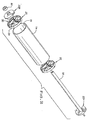
- a mounting assembly 10 arranged in a roll cassette 12 which is used to feed photosensitive sheet material to a platemaker.
- the mounting assembly 10 supports a roll of photosensitive sheet material 14 wrapped on a paperboard core 16.
- a mounting shaft 18 extends axially through the core 16.
- An end plug 20 and a mounting plate 22 are provided at each end of the shaft 18.
- Each end plug 20 comprises a cylindrical band 24 of stiffly flexible plastic material having ends 26 and 28 which define a longitudinal gap 30 therein.
- a plurality of radial webs 32, 34, and 36 extend inwardly from the band 24, and the webs 32 and 34 are provided with elongated apertures 38 and 40 having parallel longitudinal sides 42 and major axes ⁇ 1 and ⁇ 2 which define acute angles of about 3° with a first diameter D of the end plug 20.
- the web 36 is provided with a third elongated aperture 44 having parallel elongated sides 46 and a major axis ⁇ which is perpendicular to the diameter D and which is colinear with another diameter of the plug 20.
- the web 36 is further provided with a fourth elongated aperture 48 having parallel elongated sides 50 and a major axis which is colinear with the major axis ⁇ and, therefore, the other diameter of the plug 20.
- Each web 32, 34 and 36 is defined by stiffening sides 52 having an axial extent corresponding to the axial extent of the band 24.
- a stiffing rib 54 extends radially inwardly from the band 24 between the webs 32, 34 and 36 and coplanar thereto.
- the plug 20 is preferably injection molded from a suitable thermoplastic, and since it is a low cost item, it may be bonded to the paperboard core to be disposed therewith.
- the end plugs 20 are constructed so that they have an initial outside band diameter which is slightly larger than the maximum inside diameter of a core 16 so that the gap 30 is narrowed and the band 24 assumes a smaller diameter when the plugs 20 are inserted and cemented within the open ends of the core 16.
- a plurality of tabs 56 extend radially outwardly from the band 24 and engage the ends of the core 16 to ensure that the plugs 20 are properly seated in the core 16.
- the shaft 18 is mounted through the aperture 48 in each plug 20 and a mounting plate 22 is mounted on each protruding end of the shaft 18.
- Each mounting plate 22 may be metal or plastic and comprises a base 58 having a plurality of raised sectors 60, 62, and 64.
- Each mounting plate 22 has a central cylindrical opening 66 which receives the end of the shaft 18 with a close fit.
- the mounting plate 22A is permanently fixed to the shaft 18, and the mounting plate 22B is axially advanced on the shaft 18 until the base 58 engages the stiffening sides 52 of the plug 20.
- the sectors 60, 62 and 64 and the tab X aid in aligning the pins 68, 70 and 72 of the mounting plate 22 to the apertures 38, 40 and 44 of the plug 20.
- a plurality of cylindrical pins 68, 70, and 72 are respectively received in the apertures 38, 40, and 44.
- the diameters of the pins 68 and 70 correspond to the distance between the parallel sides 42 of the apertures 38 and 40 and the diameter of the pin 72 corresponds to the distance between the sides 46 of the aperture 44.
- the shaft 18 extends through the aperture 48 and has a diameter corresponding to the distance between the parallel elongated sides 50.
- the mounting plate 22B is pushed toward the mounting plate 22A to remove any clearance. Then a locking nut 80, which was previously loosely placed on the end portion of the mounting plate 22B, is tightened.
- the assembly is placed in the cassette 12 as is shown in Fig. 1.
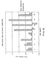
- Fig. 6 compares roll center eccentricity or runout of a roll according to this invention with a prior art loose fit mounting arrangement (no correction). By minimizing runout, the position of the photosensitive material is accurately controlled to allow the image to be accurately placed on the material.
Landscapes
- Storage Of Web-Like Or Filamentary Materials (AREA)
- Perforating, Stamping-Out Or Severing By Means Other Than Cutting (AREA)
- Paper (AREA)
- Unwinding Webs (AREA)
- Registering, Tensioning, Guiding Webs, And Rollers Therefor (AREA)
- Winding Of Webs (AREA)
- Rolls And Other Rotary Bodies (AREA)
Abstract
Description
Claims (15)
- A core end plug (20) for mounting a roll of sheet material on a shaft (18) comprising a cylindrical band (24) of stiffly flexible material (14) having ends (26, 28) defining a longitudinal gap (30) therein, a plurality of radial webs (32, 34, 36) extending inwardly from said band (24), a substantially opposite pair of said webs (32, 34) each defining an elongated aperture (38, 40) having parallel longitudinal sides (42) defining an acute angle to a first diameter (D) of said band, and another of said webs (36) defining a first elongated aperture (44) having parallel longitudinal sides (46) and having a major axis (β) aligned with a second diameter of said band.
- A core end plug according to claim 1 wherein said first diameter (D) and said second diameter are perpendicular to each other.
- A core end plug according to claim 2 wherein said second diameter bisects said gap (30).
- A core end plug according to claim 1 wherein said another of said webs (36) defines a second elongated aperture (48) having a major axis aligned with said second diameter.
- A core end plug according to claim 1 wherein said acute angle is about 3°.
- A core end plug according to claim 1 including radial tabs (56) extending outwardly from an edge of said band (24).
- A core end plug according to claim 1 including a reinforcing rib (54) extending inwardly from said band (24).
- A mounting assembly (10) for a roll of sheet material (14) wound on a cylindrical core (16) having an inside diameter and a longitudinal axis, said mounting assembly comprising a mounting shaft (18) adapted to extend axially through said core and having a longitudinal axis, an end plug (20) and a mounting plate (22) at each end of said shaft (18), with one or both of the mounting plates (22) being removably fixed to said shaft (18) at a central axis of said plate so that the axis of said shaft and said central axis are colinear, each end plug (20) comprising a cylindrical band (24) of stiffly flexible material having ends (26, 28) defining a longitudinal gap (30) therein, a plurality of radial webs (32, 34) extending inwardly from said band (24), a substantially opposite pair of said webs (32, 34) each respectively defining first and second elongated apertures (38, 40) having parallel longitudinal sides (42) defining and acute angle to a first diameter (D) of said band, and another of said webs (36) defining a third elongated aperture (44) having parallel longitudinal sides (46) and having a major axis (β) aligned with a second diameter of said band, said mounting plate (22) having first and second pins (68, 70) equidistantly spaced from said central axis and being respectively received in said first and second apertures (38, 40), said mounting plate having a third pin (72) extending into said third aperture (44), each band (24) being received in an open end of said core, and having an initial outside diameter reduced to correspond to the inside diameter of said core (16) by flexure of said band (24) and reduction of the longitudinal gap therein and reduction of an outside diameter thereof, said axis of said shaft (18), said central axis of said plate (22) and said longitudinal axis of said core (16) being colinear for all reductions of said outside diameter.
- A mounting assembly according to claim 8 wherein said first diameter (D) and second diameter are perpendicular to each other.
- A mounting assembly according to claim 8 wherein said second diameter bisects said gap (30).
- A mounting assembly according to claim 8 wherein said another of said webs (36) defines a second elongated aperture (44) having a major axis aligned with said second diameter.
- A mounting assembly according to claim 8 wherein said acute angle is about 3°.
- A mounting assembly according to claim 8 including radial tabs (56) extending outwardly from an edge of each said band (24) and engaging each said open end of said core (16) or roll of material.
- A mounting assembly according to claim 13 wherein each band (24) is adhesively secured within each said open end of said core.
- A mounting assembly according to claim 8 wherein said acute angle is at any angle which maintains collinear axes of mounting plate (22) and end plug for all reductions of outside diameter of end plug.
Priority Applications (1)
| Application Number | Priority Date | Filing Date | Title |
|---|---|---|---|
| DK01810909T DK1190975T3 (en) | 2000-09-26 | 2001-09-19 | Spool end cap for a roll of sheet material |
Applications Claiming Priority (2)
| Application Number | Priority Date | Filing Date | Title |
|---|---|---|---|
| US669820 | 1991-03-15 | ||
| US09/669,820 US6375116B1 (en) | 2000-09-26 | 2000-09-26 | Core end plug for sheet roll material |
Publications (3)
| Publication Number | Publication Date |
|---|---|
| EP1190975A2 true EP1190975A2 (en) | 2002-03-27 |
| EP1190975A3 EP1190975A3 (en) | 2003-05-07 |
| EP1190975B1 EP1190975B1 (en) | 2004-12-29 |
Family
ID=24687875
Family Applications (1)
| Application Number | Title | Priority Date | Filing Date |
|---|---|---|---|
| EP01810909A Expired - Lifetime EP1190975B1 (en) | 2000-09-26 | 2001-09-19 | Core end plug for sheet roll material |
Country Status (19)
| Country | Link |
|---|---|
| US (1) | US6375116B1 (en) |
| EP (1) | EP1190975B1 (en) |
| JP (1) | JP4737897B2 (en) |
| AR (1) | AR033576A1 (en) |
| AT (1) | ATE285974T1 (en) |
| AU (1) | AU775524B2 (en) |
| BR (1) | BR0105600B1 (en) |
| CA (1) | CA2356733C (en) |
| DE (1) | DE60108025T2 (en) |
| DK (1) | DK1190975T3 (en) |
| EC (1) | ECSP014146A (en) |
| ES (1) | ES2237545T3 (en) |
| GT (1) | GT200100195A (en) |
| HK (2) | HK1041163A2 (en) |
| IL (1) | IL145194A (en) |
| MX (1) | MXPA01009627A (en) |
| NZ (1) | NZ514114A (en) |
| SV (1) | SV2003000632A (en) |
| ZA (1) | ZA200107382B (en) |
Cited By (3)
| Publication number | Priority date | Publication date | Assignee | Title |
|---|---|---|---|---|
| EP2261151A3 (en) * | 2009-06-12 | 2011-09-14 | Owen Greenings & Mumford Limited | Dispenser |
| GB2513429A (en) * | 2013-09-04 | 2014-10-29 | Wrap Film Systems Ltd | Reel dispenser |
| CN105417289A (en) * | 2015-12-14 | 2016-03-23 | 东电化(上海)电能源有限公司 | Adapter used between tube core and winding shaft |
Families Citing this family (8)
| Publication number | Priority date | Publication date | Assignee | Title |
|---|---|---|---|---|
| US8608102B2 (en) * | 2009-10-29 | 2013-12-17 | Sonoco Development, Inc. | Modular reel structure |
| CN102225728B (en) * | 2011-04-08 | 2012-10-10 | 江苏省电力公司太仓市供电公司 | Transmission shaft spacing mechanism for wire rewinding machine |
| US9908737B2 (en) * | 2011-10-07 | 2018-03-06 | Perfectvision Manufacturing, Inc. | Cable reel and reel carrying caddy |
| WO2014014905A1 (en) * | 2012-07-19 | 2014-01-23 | Geami Ltd.. | Apparatus and method for dispensing cushioning wrap material |
| JP6286893B2 (en) * | 2013-06-25 | 2018-03-07 | 日立化成株式会社 | Core holder, core unit and film adhesive set |
| US9770142B2 (en) * | 2013-12-02 | 2017-09-26 | Dispensing Dynamics International, Llc | Multi-piece support for paper roll product |
| WO2019032447A1 (en) * | 2017-08-07 | 2019-02-14 | Ranpak Corp. | Compact manual dunnage conversion apparatus |
| US11247707B2 (en) * | 2019-04-17 | 2022-02-15 | Cerro Wire Llc | Reel adapter |
Family Cites Families (8)
| Publication number | Priority date | Publication date | Assignee | Title |
|---|---|---|---|---|
| US2320068A (en) * | 1941-09-16 | 1943-05-25 | Earl R Crebbs | Rewind core and endpiece |
| DE1254917B (en) * | 1963-02-13 | 1967-11-23 | Otto Hachtmann | Set of clamping rollers for the centric coupling of a cylindrical sleeve with a shaft with clamping surfaces |
| US3567146A (en) * | 1969-06-02 | 1971-03-02 | Us Caster Corp | End core for rolls of paper |
| FR2228299B1 (en) * | 1973-05-04 | 1977-09-02 | Radiotechnique Compelec | |
| US4125229A (en) * | 1977-11-15 | 1978-11-14 | Macfield Texturing | Apparatus for restarting a broken thread or yarn strand during a winding process |
| JPS581043A (en) * | 1981-06-24 | 1983-01-06 | Sumitomo Metal Ind Ltd | High strength alloy having superior stress corrosion cracking resistance for oil well pipe |
| JPS6081955A (en) * | 1983-10-11 | 1985-05-10 | Nec Corp | Display system of number of calling subscriber |
| JP2519943B2 (en) * | 1987-07-24 | 1996-07-31 | 富士写真フイルム株式会社 | Roll sheet packaging |
-
2000
- 2000-09-26 US US09/669,820 patent/US6375116B1/en not_active Expired - Lifetime
-
2001
- 2001-08-30 IL IL145194A patent/IL145194A/en not_active IP Right Cessation
- 2001-09-05 AU AU68789/01A patent/AU775524B2/en not_active Ceased
- 2001-09-05 CA CA002356733A patent/CA2356733C/en not_active Expired - Fee Related
- 2001-09-06 ZA ZA200107382A patent/ZA200107382B/en unknown
- 2001-09-12 NZ NZ514114A patent/NZ514114A/en unknown
- 2001-09-19 DK DK01810909T patent/DK1190975T3/en active
- 2001-09-19 EP EP01810909A patent/EP1190975B1/en not_active Expired - Lifetime
- 2001-09-19 SV SV2001000632A patent/SV2003000632A/en not_active Application Discontinuation
- 2001-09-19 ES ES01810909T patent/ES2237545T3/en not_active Expired - Lifetime
- 2001-09-19 DE DE60108025T patent/DE60108025T2/en not_active Expired - Lifetime
- 2001-09-19 AT AT01810909T patent/ATE285974T1/en not_active IP Right Cessation
- 2001-09-25 GT GT200100195A patent/GT200100195A/en unknown
- 2001-09-25 AR ARP010104508A patent/AR033576A1/en active IP Right Grant
- 2001-09-25 BR BRPI0105600-0A patent/BR0105600B1/en not_active IP Right Cessation
- 2001-09-25 JP JP2001291547A patent/JP4737897B2/en not_active Expired - Fee Related
- 2001-09-25 EC EC2001004146A patent/ECSP014146A/en unknown
- 2001-09-25 MX MXPA01009627A patent/MXPA01009627A/en active IP Right Grant
- 2001-09-26 HK HK01106809A patent/HK1041163A2/en not_active IP Right Cessation
-
2002
- 2002-06-04 HK HK02104243.5A patent/HK1042462A1/en unknown
Cited By (4)
| Publication number | Priority date | Publication date | Assignee | Title |
|---|---|---|---|---|
| EP2261151A3 (en) * | 2009-06-12 | 2011-09-14 | Owen Greenings & Mumford Limited | Dispenser |
| GB2513429A (en) * | 2013-09-04 | 2014-10-29 | Wrap Film Systems Ltd | Reel dispenser |
| GB2513429B (en) * | 2013-09-04 | 2015-09-09 | Wrap Film Systems Ltd | Reel Dispenser |
| CN105417289A (en) * | 2015-12-14 | 2016-03-23 | 东电化(上海)电能源有限公司 | Adapter used between tube core and winding shaft |
Also Published As
| Publication number | Publication date |
|---|---|
| EP1190975A3 (en) | 2003-05-07 |
| EP1190975B1 (en) | 2004-12-29 |
| HK1041163A2 (en) | 2002-06-21 |
| AU6878901A (en) | 2002-03-28 |
| IL145194A (en) | 2006-12-31 |
| AU775524B2 (en) | 2004-08-05 |
| DK1190975T3 (en) | 2005-05-09 |
| ZA200107382B (en) | 2002-08-05 |
| CA2356733C (en) | 2008-03-18 |
| JP2002128393A (en) | 2002-05-09 |
| IL145194A0 (en) | 2002-06-30 |
| NZ514114A (en) | 2001-09-28 |
| HK1042462A1 (en) | 2002-08-16 |
| ECSP014146A (en) | 2002-04-23 |
| DE60108025T2 (en) | 2006-02-09 |
| CA2356733A1 (en) | 2002-03-06 |
| JP4737897B2 (en) | 2011-08-03 |
| ES2237545T3 (en) | 2005-08-01 |
| ATE285974T1 (en) | 2005-01-15 |
| AR033576A1 (en) | 2003-12-26 |
| BR0105600B1 (en) | 2009-01-13 |
| DE60108025D1 (en) | 2005-02-03 |
| US6375116B1 (en) | 2002-04-23 |
| BR0105600A (en) | 2002-07-23 |
| SV2003000632A (en) | 2003-08-19 |
| GT200100195A (en) | 2002-07-18 |
| MXPA01009627A (en) | 2003-09-04 |
Similar Documents
| Publication | Publication Date | Title |
|---|---|---|
| US6375116B1 (en) | Core end plug for sheet roll material | |
| US20100051738A1 (en) | Coreless Roll Mounting Apparatus | |
| JP2000508284A (en) | Roll support hub | |
| JP2003267596A (en) | Recording paper roll holder device | |
| US6736349B1 (en) | Device for supporting a strip in the wound or spooled condition | |
| US4610555A (en) | Universal ribbon spool for typewriters and other machines | |
| JPS6119529B2 (en) | ||
| WO1990011957A1 (en) | Core for winding a web of deformable material | |
| US12187562B2 (en) | Chuck with improved torque transmission and centralization | |
| KR101915619B1 (en) | Clamping housing for fixing paper tube of printer | |
| EP0925244B1 (en) | Method for unwinding rolls of paper | |
| JP3088477B2 (en) | Device for clamping plates to the plate cylinder of a rotary printing press | |
| US5717495A (en) | Construction for holding recording paper roll | |
| JPH11254774A (en) | Spool for winding material of thread type or strip type | |
| JP2001031329A (en) | Paper tube | |
| US3439881A (en) | One-piece molded spool,winding core or the like | |
| JP3850125B2 (en) | Branch pipe positioning device in winder | |
| JPH0628526Y2 (en) | Roll paper holder | |
| US5351901A (en) | Hub tensioning device | |
| JPS6234915Y2 (en) | ||
| JPH065316Y2 (en) | Roll paper support device | |
| JPH11139633A (en) | Base paper roll supporting device | |
| KR200171832Y1 (en) | Reinforcing ring for a paper tube | |
| JP3400030B2 (en) | Paint transfer tool | |
| JPH0540030Y2 (en) |
Legal Events
| Date | Code | Title | Description |
|---|---|---|---|
| PUAI | Public reference made under article 153(3) epc to a published international application that has entered the european phase |
Free format text: ORIGINAL CODE: 0009012 |
|
| AK | Designated contracting states |
Kind code of ref document: A2 Designated state(s): AT BE CH CY DE DK ES FI FR GB GR IE IT LI LU MC NL PT SE TR |
|
| AX | Request for extension of the european patent |
Free format text: AL;LT;LV;MK;RO;SI |
|
| PUAL | Search report despatched |
Free format text: ORIGINAL CODE: 0009013 |
|
| AK | Designated contracting states |
Designated state(s): AT BE CH CY DE DK ES FI FR GB GR IE IT LI LU MC NL PT SE TR |
|
| AX | Request for extension of the european patent |
Extension state: AL LT LV MK RO SI |
|
| 17P | Request for examination filed |
Effective date: 20030528 |
|
| 17Q | First examination report despatched |
Effective date: 20030917 |
|
| AKX | Designation fees paid |
Designated state(s): AT BE CH CY DE DK ES FI FR GB GR IE IT LI LU MC NL PT SE TR |
|
| AXX | Extension fees paid |
Extension state: SI Payment date: 20031107 Extension state: LV Payment date: 20031107 Extension state: MK Payment date: 20031107 Extension state: RO Payment date: 20031107 Extension state: AL Payment date: 20031107 Extension state: LT Payment date: 20031107 |
|
| DAX | Request for extension of the european patent (deleted) | ||
| GRAP | Despatch of communication of intention to grant a patent |
Free format text: ORIGINAL CODE: EPIDOSNIGR1 |
|
| GRAS | Grant fee paid |
Free format text: ORIGINAL CODE: EPIDOSNIGR3 |
|
| GRAA | (expected) grant |
Free format text: ORIGINAL CODE: 0009210 |
|
| AK | Designated contracting states |
Kind code of ref document: B1 Designated state(s): AT BE CH CY DE DK ES FI FR GB GR IE IT LI LU MC NL PT SE TR |
|
| PG25 | Lapsed in a contracting state [announced via postgrant information from national office to epo] |
Ref country code: AT Free format text: LAPSE BECAUSE OF FAILURE TO SUBMIT A TRANSLATION OF THE DESCRIPTION OR TO PAY THE FEE WITHIN THE PRESCRIBED TIME-LIMIT Effective date: 20041229 Ref country code: TR Free format text: LAPSE BECAUSE OF FAILURE TO SUBMIT A TRANSLATION OF THE DESCRIPTION OR TO PAY THE FEE WITHIN THE PRESCRIBED TIME-LIMIT Effective date: 20041229 Ref country code: FI Free format text: LAPSE BECAUSE OF FAILURE TO SUBMIT A TRANSLATION OF THE DESCRIPTION OR TO PAY THE FEE WITHIN THE PRESCRIBED TIME-LIMIT Effective date: 20041229 |
|
| REG | Reference to a national code |
Ref country code: GB Ref legal event code: FG4D |
|
| REG | Reference to a national code |
Ref country code: CH Ref legal event code: EP |
|
| REG | Reference to a national code |
Ref country code: IE Ref legal event code: FG4D |
|
| REF | Corresponds to: |
Ref document number: 60108025 Country of ref document: DE Date of ref document: 20050203 Kind code of ref document: P |
|
| PG25 | Lapsed in a contracting state [announced via postgrant information from national office to epo] |
Ref country code: SE Free format text: LAPSE BECAUSE OF FAILURE TO SUBMIT A TRANSLATION OF THE DESCRIPTION OR TO PAY THE FEE WITHIN THE PRESCRIBED TIME-LIMIT Effective date: 20050329 |
|
| REG | Reference to a national code |
Ref country code: CH Ref legal event code: NV Representative=s name: PATENTS & TECHNOLOGY SURVEYS SA |
|
| REG | Reference to a national code |
Ref country code: DK Ref legal event code: T3 |
|
| REG | Reference to a national code |
Ref country code: GR Ref legal event code: EP Ref document number: 20050401501 Country of ref document: GR |
|
| REG | Reference to a national code |
Ref country code: ES Ref legal event code: FG2A Ref document number: 2237545 Country of ref document: ES Kind code of ref document: T3 |
|
| PG25 | Lapsed in a contracting state [announced via postgrant information from national office to epo] |
Ref country code: CY Free format text: LAPSE BECAUSE OF FAILURE TO SUBMIT A TRANSLATION OF THE DESCRIPTION OR TO PAY THE FEE WITHIN THE PRESCRIBED TIME-LIMIT Effective date: 20050919 |
|
| PG25 | Lapsed in a contracting state [announced via postgrant information from national office to epo] |
Ref country code: LU Free format text: LAPSE BECAUSE OF NON-PAYMENT OF DUE FEES Effective date: 20050930 Ref country code: MC Free format text: LAPSE BECAUSE OF NON-PAYMENT OF DUE FEES Effective date: 20050930 |
|
| PLBE | No opposition filed within time limit |
Free format text: ORIGINAL CODE: 0009261 |
|
| STAA | Information on the status of an ep patent application or granted ep patent |
Free format text: STATUS: NO OPPOSITION FILED WITHIN TIME LIMIT |
|
| 26N | No opposition filed |
Effective date: 20050930 |
|
| ET | Fr: translation filed | ||
| PGFP | Annual fee paid to national office [announced via postgrant information from national office to epo] |
Ref country code: FR Payment date: 20060810 Year of fee payment: 6 |
|
| PGFP | Annual fee paid to national office [announced via postgrant information from national office to epo] |
Ref country code: DK Payment date: 20060811 Year of fee payment: 6 Ref country code: NL Payment date: 20060811 Year of fee payment: 6 |
|
| PGFP | Annual fee paid to national office [announced via postgrant information from national office to epo] |
Ref country code: CH Payment date: 20060815 Year of fee payment: 6 |
|
| PGFP | Annual fee paid to national office [announced via postgrant information from national office to epo] |
Ref country code: IE Payment date: 20060821 Year of fee payment: 6 |
|
| PGFP | Annual fee paid to national office [announced via postgrant information from national office to epo] |
Ref country code: ES Payment date: 20060904 Year of fee payment: 6 |
|
| PGFP | Annual fee paid to national office [announced via postgrant information from national office to epo] |
Ref country code: IT Payment date: 20060930 Year of fee payment: 6 |
|
| PG25 | Lapsed in a contracting state [announced via postgrant information from national office to epo] |
Ref country code: PT Free format text: LAPSE BECAUSE OF NON-PAYMENT OF DUE FEES Effective date: 20050529 |
|
| REG | Reference to a national code |
Ref country code: HK Ref legal event code: WD Ref document number: 1042462 Country of ref document: HK |
|
| REG | Reference to a national code |
Ref country code: DK Ref legal event code: EBP |
|
| REG | Reference to a national code |
Ref country code: CH Ref legal event code: PL |
|
| PG25 | Lapsed in a contracting state [announced via postgrant information from national office to epo] |
Ref country code: NL Free format text: LAPSE BECAUSE OF NON-PAYMENT OF DUE FEES Effective date: 20080401 |
|
| PGFP | Annual fee paid to national office [announced via postgrant information from national office to epo] |
Ref country code: GR Payment date: 20070928 Year of fee payment: 7 |
|
| NLV4 | Nl: lapsed or anulled due to non-payment of the annual fee |
Effective date: 20080401 |
|
| REG | Reference to a national code |
Ref country code: IE Ref legal event code: MM4A |
|
| PG25 | Lapsed in a contracting state [announced via postgrant information from national office to epo] |
Ref country code: CH Free format text: LAPSE BECAUSE OF NON-PAYMENT OF DUE FEES Effective date: 20070930 Ref country code: LI Free format text: LAPSE BECAUSE OF NON-PAYMENT OF DUE FEES Effective date: 20070930 |
|
| REG | Reference to a national code |
Ref country code: FR Ref legal event code: ST Effective date: 20080531 |
|
| PG25 | Lapsed in a contracting state [announced via postgrant information from national office to epo] |
Ref country code: DK Free format text: LAPSE BECAUSE OF NON-PAYMENT OF DUE FEES Effective date: 20071001 Ref country code: FR Free format text: LAPSE BECAUSE OF NON-PAYMENT OF DUE FEES Effective date: 20071001 Ref country code: IE Free format text: LAPSE BECAUSE OF NON-PAYMENT OF DUE FEES Effective date: 20070919 |
|
| REG | Reference to a national code |
Ref country code: ES Ref legal event code: FD2A Effective date: 20070920 |
|
| PG25 | Lapsed in a contracting state [announced via postgrant information from national office to epo] |
Ref country code: ES Free format text: LAPSE BECAUSE OF NON-PAYMENT OF DUE FEES Effective date: 20070920 |
|
| PG25 | Lapsed in a contracting state [announced via postgrant information from national office to epo] |
Ref country code: IT Free format text: LAPSE BECAUSE OF NON-PAYMENT OF DUE FEES Effective date: 20070919 |
|
| PG25 | Lapsed in a contracting state [announced via postgrant information from national office to epo] |
Ref country code: GR Free format text: LAPSE BECAUSE OF NON-PAYMENT OF DUE FEES Effective date: 20090402 |
|
| PGFP | Annual fee paid to national office [announced via postgrant information from national office to epo] |
Ref country code: BE Payment date: 20110914 Year of fee payment: 11 |
|
| PGFP | Annual fee paid to national office [announced via postgrant information from national office to epo] |
Ref country code: GB Payment date: 20120920 Year of fee payment: 12 |
|
| BERE | Be: lapsed |
Owner name: *DICK CY A.B. Effective date: 20120930 |
|
| PG25 | Lapsed in a contracting state [announced via postgrant information from national office to epo] |
Ref country code: BE Free format text: LAPSE BECAUSE OF NON-PAYMENT OF DUE FEES Effective date: 20120930 |
|
| PGFP | Annual fee paid to national office [announced via postgrant information from national office to epo] |
Ref country code: DE Payment date: 20130930 Year of fee payment: 13 |
|
| GBPC | Gb: european patent ceased through non-payment of renewal fee |
Effective date: 20130919 |
|
| REG | Reference to a national code |
Ref country code: DE Ref legal event code: R119 Ref document number: 60108025 Country of ref document: DE Effective date: 20140401 |
|
| PG25 | Lapsed in a contracting state [announced via postgrant information from national office to epo] |
Ref country code: GB Free format text: LAPSE BECAUSE OF NON-PAYMENT OF DUE FEES Effective date: 20130919 |
|
| PG25 | Lapsed in a contracting state [announced via postgrant information from national office to epo] |
Ref country code: DE Free format text: LAPSE BECAUSE OF NON-PAYMENT OF DUE FEES Effective date: 20140401 |