EP1190952A2 - Can having can end wall provided with reclosing tab - Google Patents
Can having can end wall provided with reclosing tab Download PDFInfo
- Publication number
- EP1190952A2 EP1190952A2 EP01308082A EP01308082A EP1190952A2 EP 1190952 A2 EP1190952 A2 EP 1190952A2 EP 01308082 A EP01308082 A EP 01308082A EP 01308082 A EP01308082 A EP 01308082A EP 1190952 A2 EP1190952 A2 EP 1190952A2
- Authority
- EP
- European Patent Office
- Prior art keywords
- tab
- reclosing
- end wall
- opening
- discharge opening
- Prior art date
- Legal status (The legal status is an assumption and is not a legal conclusion. Google has not performed a legal analysis and makes no representation as to the accuracy of the status listed.)
- Withdrawn
Links
Images


Classifications
-
- B—PERFORMING OPERATIONS; TRANSPORTING
- B65—CONVEYING; PACKING; STORING; HANDLING THIN OR FILAMENTARY MATERIAL
- B65D—CONTAINERS FOR STORAGE OR TRANSPORT OF ARTICLES OR MATERIALS, e.g. BAGS, BARRELS, BOTTLES, BOXES, CANS, CARTONS, CRATES, DRUMS, JARS, TANKS, HOPPERS, FORWARDING CONTAINERS; ACCESSORIES, CLOSURES, OR FITTINGS THEREFOR; PACKAGING ELEMENTS; PACKAGES
- B65D17/00—Rigid or semi-rigid containers specially constructed to be opened by cutting or piercing, or by tearing of frangible members or portions
- B65D17/28—Rigid or semi-rigid containers specially constructed to be opened by cutting or piercing, or by tearing of frangible members or portions at lines or points of weakness
- B65D17/401—Rigid or semi-rigid containers specially constructed to be opened by cutting or piercing, or by tearing of frangible members or portions at lines or points of weakness characterised by having the line of weakness provided in an end wall
-
- B—PERFORMING OPERATIONS; TRANSPORTING
- B65—CONVEYING; PACKING; STORING; HANDLING THIN OR FILAMENTARY MATERIAL
- B65D—CONTAINERS FOR STORAGE OR TRANSPORT OF ARTICLES OR MATERIALS, e.g. BAGS, BARRELS, BOTTLES, BOXES, CANS, CARTONS, CRATES, DRUMS, JARS, TANKS, HOPPERS, FORWARDING CONTAINERS; ACCESSORIES, CLOSURES, OR FITTINGS THEREFOR; PACKAGING ELEMENTS; PACKAGES
- B65D2517/00—Containers specially constructed to be opened by cutting, piercing or tearing of wall portions, e.g. preserving cans or tins
- B65D2517/0001—Details
- B65D2517/001—Action for opening container
- B65D2517/0011—Action for opening container push-down tear panel
-
- B—PERFORMING OPERATIONS; TRANSPORTING
- B65—CONVEYING; PACKING; STORING; HANDLING THIN OR FILAMENTARY MATERIAL
- B65D—CONTAINERS FOR STORAGE OR TRANSPORT OF ARTICLES OR MATERIALS, e.g. BAGS, BARRELS, BOTTLES, BOXES, CANS, CARTONS, CRATES, DRUMS, JARS, TANKS, HOPPERS, FORWARDING CONTAINERS; ACCESSORIES, CLOSURES, OR FITTINGS THEREFOR; PACKAGING ELEMENTS; PACKAGES
- B65D2517/00—Containers specially constructed to be opened by cutting, piercing or tearing of wall portions, e.g. preserving cans or tins
- B65D2517/0001—Details
- B65D2517/0031—Reclosable openings
- B65D2517/004—Reclosable openings by means of an additional element
- B65D2517/0041—Reclosable openings by means of an additional element in the form of a cover
Definitions
- a can having a can end wall, the can end wall including an opening panel portion which is delimited by a score line so as to define a discharge opening upon being depressed downwards, an opening tab, a reclosing tab and a rivet, wherein the reclosing tab has a substantially cylindrical configuration, being closed at an upper, in use, end thereof and open, or only closed by a temporary cover, at a lower, in use, end thereof, the can end wall having a cylindrical wall part projecting therefrom around the discharge opening and with which the reclosing tab may co-operatively engage in use to thereby close the discharge opening.
- the opening tab and reclosing tab are oppositely arranged to each other and integrally connected with each other to define a tab section.
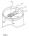
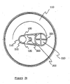
- a tab section 200 and a rivet 300 are provided on the can end wall 100.
- Three tab supporting projections 110, 120 and 120' are projectedly formed on an upper surface of the can end wall 100.
- a rivet fitting hole 140 through which the rivet 300 is fitted, is defined in the can end wall 100.
- an opening panel portion 150 is delimited by a score line on the can end wall 100. When the opening panel portion 150 is depressed downward, a discharge opening is defined and contents can be discharged out of the can.
- the three tab supporting projections 110, 120 and 120' and the opening panel portion 150 are opposed to each other while being centered on the rivet fitting hole 140.
- the three tab supporting projections 110, 120 and 120' are formed by pressing the can end wall 100 in a manner such that the tab supporting projections 110, 120 and 120' frusto-conically project from the upper surface of the can end wall 100.
- One tab supporting projection 110 of the three tab supporting projections 110, 120 and 120' is formed higher than other two tab supporting projections 120 and 120', in a manner such that the one tab supporting projection 110 can support a reclosing tab 220 as will be described later, which constitute the tab section 200.
- the opening panel portion 150 has substantially a circular plate-shaped configuration.
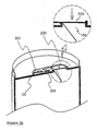
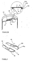
- the tab section 200 comprises an opening tab 210 and the reclosing tab 220 which are oppositely arranged to each other and integrally connected with each other. While the opening tab 210 has the same structure as the conventional opening tab, the reclosing tab 220 has substantially a cylindrical configuration which is closed at an upper end thereof and opened at a lower end thereof. A cylindrical side wall of the reclosing tab 220 has a curved side wall portion 222 and a cut-out portion. The cut-out portion is formed in a rotating direction of the reclosing tab 220, and a remaining portion of the cylindrical side wall of the reclosing tab 220 defines the curved side wall portion 222 (see FIG. 6). As best shown in FIG.
- the discharge opening of the can by grasping the rotation knob 221 of the reclosing tab 220 and rotating the tab section 200 by 180°, as the reclosing tab 220 is placed on the upper end of the cylindrical wall part 151 of the can end wall 100, the discharge opening can be effectively reclosed.
- the three tab supporting projections 110, 120 and 120' and the rivet 300 cooperatively function as the leverage which holds the opening tab 210 in the raised location, and thereby, the reclosing tab 220 can be brought into close contact with the upper end of the cylindrical wall part 151.
- an opened lower end of the reclosing tab 220 of the tab section 200 is closed by a vinyl sheet or an aluminum foil (not shown) in the course of manufacturing the reclosing tab 220, whereby the reclosing tab 220 can be used in a state wherein sanitization is ensured.
- the vinyl sheet or the aluminum foil which is attached to the opened lower end of the reclosing tab 220 can be detached therefrom by the hand.
- the can having the can end wall provided with the reclosing tab according to the present invention affords advantages in that, since the reclosing tab has a simple structure, the can is able to be manufactured in an easy manner and thereby economy is improved. Also, the can is manufactured in such a way as not to significantly change an existing manufacturing process. in particular, because the possibility of a fingernail of the user to be broken or damaged upon pulling upward a handle end of a tab section is eliminated and a discharge opening can be easily opened and reclosed, user convenience is ensured.
- a configuration of the can end wall according to the present invention is not altered, and thereby, the effective use of shelf, storage and shipping space, that is, stackability and shippability of the can are not adversely influenced. Furthermore, the can end wall according to the present invention exhibits excellent sealing capability upon reclosing the discharge opening.
- the reclosing tab does not raise a consumer sanitary question.
Landscapes
- Engineering & Computer Science (AREA)
- Mechanical Engineering (AREA)
- Containers Opened By Tearing Frangible Portions (AREA)
Abstract
Description
- A great deal of effort and cost is required for manufacturing those can reclosing devices.
- Significant retooling of existing equipment is required.
- Reliable sealing of a discharge opening cannot be ensured, and those can reclosing devices are inconvenient to use.
- Due to the fact that lower surfaces of reclosing tabs are
exposed to the outside, those can reclosing devices raise a
consumer sanitary question.
- Since entire configurations of cans are changed, the effective use of shelf, storage and shipping space, that is, stackability and shippability of the cans is reduced.
Claims (11)
- A can having a can end wall, the can end wall including an opening panel portion which is delimited by a score line so as to define a discharge opening upon being depressed downwards, an opening tab, a reclosing tab and a rivet, wherein the reclosing tab has a substantially cylindrical configuration, being closed at an upper, in use, end thereof and open, or only closed by a temporary cover, at a lower, in use, end thereof, the can end wall having a cylindrical wall part projecting therefrom around the discharge opening and with which the reclosing tab may co-operatively engage in use to thereby close the discharge opening.
- A can as claimed in claim 1, wherein the opening tab and reclosing tab are oppositely arranged to each other and integrally connected with each other to define a tab section.
- A can as claimed in claim 1 or claim 2, wherein a plurality of tab supporting projections are provided on an upper surface of the can end wall.
- A can as claimed in claim 3, wherein the tab supporting projections are generally frusto-conical or hemispherical in shape.
- A can as claimed in any preceding claim, wherein a rotation knob is provided projecting from an upper surface of the tab section.
- A can as claimed in any preceding claim, wherein the lower end of the reclosing tab is closed by a temporary cover comprising a vinyl sheet or aluminium foil in the course of manufacturing the reclosing tab.
- A can as claimed in any preceding claim, wherein there are at least three tab supporting projections formed on the can end wall and at least one of the tab supporting projections is higher than others of the tab supporting projections.
- A can as claimed in any preceding claim, wherein the substantially cylindrical configuration of the reclosing tab comprises a cylindrical side wall having a curved side wall portion and a cut-out portion, the cut-out portion being formed on a side of the reclosing tab so that when the tab is rotated toward the discharge opening the reclosing tab may slot over the cylindrical side wall portion of the can end wall.
- A can as claimed in any preceding claim, wherein the reclosing tab (220) has on its cylindrical part (222) an annular flange (223) which co-operatively engages with an annular groove (152) in the substantially cylindrical wall part (151) of the can end wall (100).
- A can as claimed in claim 8 and claim 9 wherein the annular flange (223) has said cut-out portion (224) formed therein.
- A can having a can end wall provided with a reclosing tab substantially as hereinbefore described with reference to the accompanying drawings.
Priority Applications (1)
| Application Number | Priority Date | Filing Date | Title |
|---|---|---|---|
| EP01308082A EP1190952A3 (en) | 2000-09-25 | 2001-09-24 | Can having can end wall provided with reclosing tab |
Applications Claiming Priority (5)
| Application Number | Priority Date | Filing Date | Title |
|---|---|---|---|
| KR20000056238 | 2000-09-25 | ||
| KR2000056238 | 2000-09-25 | ||
| KR1020000067226A KR100329127B1 (en) | 2000-09-25 | 2000-11-13 | Beverage can lid provided with reclousable tab |
| KR2000067226 | 2000-11-13 | ||
| EP01308082A EP1190952A3 (en) | 2000-09-25 | 2001-09-24 | Can having can end wall provided with reclosing tab |
Publications (2)
| Publication Number | Publication Date |
|---|---|
| EP1190952A2 true EP1190952A2 (en) | 2002-03-27 |
| EP1190952A3 EP1190952A3 (en) | 2004-01-07 |
Family
ID=29740404
Family Applications (1)
| Application Number | Title | Priority Date | Filing Date |
|---|---|---|---|
| EP01308082A Withdrawn EP1190952A3 (en) | 2000-09-25 | 2001-09-24 | Can having can end wall provided with reclosing tab |
Country Status (1)
| Country | Link |
|---|---|
| EP (1) | EP1190952A3 (en) |
Cited By (4)
| Publication number | Priority date | Publication date | Assignee | Title |
|---|---|---|---|---|
| WO2009103817A1 (en) | 2008-02-21 | 2009-08-27 | Christian Bratsch | Cover of a container |
| WO2010094793A2 (en) | 2009-02-23 | 2010-08-26 | Xolution Gmbh | Lid of a container |
| WO2010115911A1 (en) | 2009-04-07 | 2010-10-14 | Xolution Gmbh | Reclosable closure of a liquid container |
| WO2012031994A1 (en) | 2010-09-07 | 2012-03-15 | Xolution Gmbh | A lid of a container |
Family Cites Families (4)
| Publication number | Priority date | Publication date | Assignee | Title |
|---|---|---|---|---|
| US4685849A (en) * | 1985-05-29 | 1987-08-11 | Aluminum Company Of America | Method for making an easy opening container end closure |
| JPH0777902B2 (en) * | 1990-10-31 | 1995-08-23 | ブランコ、アルセニオ グテエレサ | Beverage metal container closure |
| US5186348A (en) * | 1991-04-24 | 1993-02-16 | Can Do Associates | Can end with lock open and lock closed tab operated by a pull ring |
| GB2255081A (en) * | 1991-04-25 | 1992-10-28 | Umur Talip Erte | Re-sealable portable containers |
-
2001
- 2001-09-24 EP EP01308082A patent/EP1190952A3/en not_active Withdrawn
Cited By (9)
| Publication number | Priority date | Publication date | Assignee | Title |
|---|---|---|---|---|
| WO2009103817A1 (en) | 2008-02-21 | 2009-08-27 | Christian Bratsch | Cover of a container |
| US9272823B2 (en) | 2008-02-21 | 2016-03-01 | Xolution Gmbh | Lid of a container |
| WO2010094793A2 (en) | 2009-02-23 | 2010-08-26 | Xolution Gmbh | Lid of a container |
| AT507950B1 (en) * | 2009-02-23 | 2011-07-15 | Xolution Gmbh | COVER OF A CONTAINER |
| US9162796B2 (en) | 2009-02-23 | 2015-10-20 | Xolution Gmbh | Lid of a container |
| WO2010115911A1 (en) | 2009-04-07 | 2010-10-14 | Xolution Gmbh | Reclosable closure of a liquid container |
| US8720740B2 (en) | 2009-04-07 | 2014-05-13 | Xolution Gmbh | Reclosable closure of a liquid container |
| WO2012031994A1 (en) | 2010-09-07 | 2012-03-15 | Xolution Gmbh | A lid of a container |
| US10781012B2 (en) | 2010-09-07 | 2020-09-22 | Xolution Gmbh | Lid of a container |
Also Published As
| Publication number | Publication date |
|---|---|
| EP1190952A3 (en) | 2004-01-07 |
Similar Documents
| Publication | Publication Date | Title |
|---|---|---|
| US7484638B2 (en) | Plastic drink-through cup lid with fold-back tab | |
| AU705829B2 (en) | Raised pouring spout, recessed in an inverted position in a can lid | |
| US6290084B1 (en) | Rotary protective cover attachment for beverage container | |
| US4262815A (en) | Conical can end with a gate and opening tab at the cone apex | |
| US5273176A (en) | Reclosable cover for a beverage can | |
| US5285919A (en) | Beverage container with air access for direct drinking | |
| US5509568A (en) | Drink-through lid for disposable cup | |
| US20240109685A1 (en) | Can lid, can and method for manufacturing a can lid | |
| US5720412A (en) | Container cover having a screen | |
| CN101910008B (en) | Can end | |
| US8783495B2 (en) | Can end | |
| US9181007B2 (en) | Beverage can end with vent port | |
| US5346087A (en) | Reinforced beverage can end with push down gate | |
| US20030218017A1 (en) | Drink-through lid for a beverage container | |
| US4982862A (en) | Digitally openable, resealable container closure | |
| US4480763A (en) | Beverage container opening means | |
| US6450359B1 (en) | Sanitary beverage can lid | |
| EP1190952A2 (en) | Can having can end wall provided with reclosing tab | |
| US5148935A (en) | Venting resealable container closure and associated closure container-combination | |
| US4265367A (en) | Easy opening top closure member for a container | |
| WO1986006702A1 (en) | Easy-open closure | |
| US4909407A (en) | Can lid with easy-open tab | |
| US20050051552A1 (en) | Self-closing lid for beverage cups and the like | |
| GB2379917A (en) | A Reclosable Tab for Beverage Cans | |
| WO2004110891A1 (en) | Cap of can for drinking and can for drinking having the same |
Legal Events
| Date | Code | Title | Description |
|---|---|---|---|
| PUAI | Public reference made under article 153(3) epc to a published international application that has entered the european phase |
Free format text: ORIGINAL CODE: 0009012 |
|
| AK | Designated contracting states |
Kind code of ref document: A2 Designated state(s): AT BE CH CY DE DK ES FI FR GB GR IE IT LI LU MC NL PT SE TR |
|
| AX | Request for extension of the european patent |
Free format text: AL;LT;LV;MK;RO;SI |
|
| PUAL | Search report despatched |
Free format text: ORIGINAL CODE: 0009013 |
|
| RIC1 | Information provided on ipc code assigned before grant |
Ipc: 7B 65D 17/16 B Ipc: 7B 65D 17/32 A |
|
| AK | Designated contracting states |
Kind code of ref document: A3 Designated state(s): AT BE CH CY DE DK ES FI FR GB GR IE IT LI LU MC NL PT SE TR |
|
| AX | Request for extension of the european patent |
Extension state: AL LT LV MK RO SI |
|
| STAA | Information on the status of an ep patent application or granted ep patent |
Free format text: STATUS: THE APPLICATION IS DEEMED TO BE WITHDRAWN |
|
| AKX | Designation fees paid | ||
| 18D | Application deemed to be withdrawn |
Effective date: 20040401 |
|
| REG | Reference to a national code |
Ref country code: DE Ref legal event code: 8566 |