EP1189672B1 - Fluid handling apparatus and flow control assembly therefor - Google Patents
Fluid handling apparatus and flow control assembly therefor Download PDFInfo
- Publication number
- EP1189672B1 EP1189672B1 EP00919760A EP00919760A EP1189672B1 EP 1189672 B1 EP1189672 B1 EP 1189672B1 EP 00919760 A EP00919760 A EP 00919760A EP 00919760 A EP00919760 A EP 00919760A EP 1189672 B1 EP1189672 B1 EP 1189672B1
- Authority
- EP
- European Patent Office
- Prior art keywords
- fluid
- chamber
- outlet
- inlet
- housing
- Prior art date
- Legal status (The legal status is an assumption and is not a legal conclusion. Google has not performed a legal analysis and makes no representation as to the accuracy of the status listed.)
- Expired - Lifetime
Links
- 239000012530 fluid Substances 0.000 title claims abstract description 66
- 239000002131 composite material Substances 0.000 claims 1
- 230000013011 mating Effects 0.000 claims 1
- 230000002093 peripheral effect Effects 0.000 claims 1
- 230000000717 retained effect Effects 0.000 claims 1
- 238000007789 sealing Methods 0.000 description 21
- 239000007788 liquid Substances 0.000 description 18
- 238000010276 construction Methods 0.000 description 6
- 230000003750 conditioning effect Effects 0.000 description 4
- 239000000463 material Substances 0.000 description 4
- 238000009434 installation Methods 0.000 description 3
- 230000000712 assembly Effects 0.000 description 2
- 238000000429 assembly Methods 0.000 description 2
- 229920001971 elastomer Polymers 0.000 description 2
- 239000000806 elastomer Substances 0.000 description 2
- -1 polypropylene Polymers 0.000 description 2
- 239000004698 Polyethylene Substances 0.000 description 1
- 239000004743 Polypropylene Substances 0.000 description 1
- 238000005299 abrasion Methods 0.000 description 1
- 230000000903 blocking effect Effects 0.000 description 1
- 230000002708 enhancing effect Effects 0.000 description 1
- HQQADJVZYDDRJT-UHFFFAOYSA-N ethene;prop-1-ene Chemical group C=C.CC=C HQQADJVZYDDRJT-UHFFFAOYSA-N 0.000 description 1
- 238000012986 modification Methods 0.000 description 1
- 230000004048 modification Effects 0.000 description 1
- 150000002825 nitriles Chemical class 0.000 description 1
- 230000000737 periodic effect Effects 0.000 description 1
- 229920003023 plastic Polymers 0.000 description 1
- 239000004033 plastic Substances 0.000 description 1
- 229920000573 polyethylene Polymers 0.000 description 1
- 229920001155 polypropylene Polymers 0.000 description 1
Images


Classifications
-
- F—MECHANICAL ENGINEERING; LIGHTING; HEATING; WEAPONS; BLASTING
- F16—ENGINEERING ELEMENTS AND UNITS; GENERAL MEASURES FOR PRODUCING AND MAINTAINING EFFECTIVE FUNCTIONING OF MACHINES OR INSTALLATIONS; THERMAL INSULATION IN GENERAL
- F16K—VALVES; TAPS; COCKS; ACTUATING-FLOATS; DEVICES FOR VENTING OR AERATING
- F16K27/00—Construction of housing; Use of materials therefor
- F16K27/06—Construction of housing; Use of materials therefor of taps or cocks
- F16K27/067—Construction of housing; Use of materials therefor of taps or cocks with spherical plugs
-
- B—PERFORMING OPERATIONS; TRANSPORTING
- B01—PHYSICAL OR CHEMICAL PROCESSES OR APPARATUS IN GENERAL
- B01D—SEPARATION
- B01D29/00—Filters with filtering elements stationary during filtration, e.g. pressure or suction filters, not covered by groups B01D24/00 - B01D27/00; Filtering elements therefor
- B01D29/11—Filters with filtering elements stationary during filtration, e.g. pressure or suction filters, not covered by groups B01D24/00 - B01D27/00; Filtering elements therefor with bag, cage, hose, tube, sleeve or like filtering elements
- B01D29/31—Self-supporting filtering elements
- B01D29/35—Self-supporting filtering elements arranged for outward flow filtration
-
- B—PERFORMING OPERATIONS; TRANSPORTING
- B01—PHYSICAL OR CHEMICAL PROCESSES OR APPARATUS IN GENERAL
- B01D—SEPARATION
- B01D29/00—Filters with filtering elements stationary during filtration, e.g. pressure or suction filters, not covered by groups B01D24/00 - B01D27/00; Filtering elements therefor
- B01D29/96—Filters with filtering elements stationary during filtration, e.g. pressure or suction filters, not covered by groups B01D24/00 - B01D27/00; Filtering elements therefor in which the filtering elements are moved between filtering operations; Particular measures for removing or replacing the filtering elements; Transport systems for filters
-
- B—PERFORMING OPERATIONS; TRANSPORTING
- B01—PHYSICAL OR CHEMICAL PROCESSES OR APPARATUS IN GENERAL
- B01D—SEPARATION
- B01D35/00—Filtering devices having features not specifically covered by groups B01D24/00 - B01D33/00, or for applications not specifically covered by groups B01D24/00 - B01D33/00; Auxiliary devices for filtration; Filter housing constructions
- B01D35/12—Devices for taking out of action one or more units of multi- unit filters, e.g. for regeneration
-
- Y—GENERAL TAGGING OF NEW TECHNOLOGICAL DEVELOPMENTS; GENERAL TAGGING OF CROSS-SECTIONAL TECHNOLOGIES SPANNING OVER SEVERAL SECTIONS OF THE IPC; TECHNICAL SUBJECTS COVERED BY FORMER USPC CROSS-REFERENCE ART COLLECTIONS [XRACs] AND DIGESTS
- Y10—TECHNICAL SUBJECTS COVERED BY FORMER USPC
- Y10T—TECHNICAL SUBJECTS COVERED BY FORMER US CLASSIFICATION
- Y10T137/00—Fluid handling
- Y10T137/7504—Removable valve head and seat unit
- Y10T137/7668—Retained by bonnet or closure
-
- Y—GENERAL TAGGING OF NEW TECHNOLOGICAL DEVELOPMENTS; GENERAL TAGGING OF CROSS-SECTIONAL TECHNOLOGIES SPANNING OVER SEVERAL SECTIONS OF THE IPC; TECHNICAL SUBJECTS COVERED BY FORMER USPC CROSS-REFERENCE ART COLLECTIONS [XRACs] AND DIGESTS
- Y10—TECHNICAL SUBJECTS COVERED BY FORMER USPC
- Y10T—TECHNICAL SUBJECTS COVERED BY FORMER US CLASSIFICATION
- Y10T137/00—Fluid handling
- Y10T137/8593—Systems
- Y10T137/86493—Multi-way valve unit
- Y10T137/86509—Sequentially progressive opening or closing of plural ports
- Y10T137/86517—With subsequent closing of first port
- Y10T137/86533—Rotary
-
- Y—GENERAL TAGGING OF NEW TECHNOLOGICAL DEVELOPMENTS; GENERAL TAGGING OF CROSS-SECTIONAL TECHNOLOGIES SPANNING OVER SEVERAL SECTIONS OF THE IPC; TECHNICAL SUBJECTS COVERED BY FORMER USPC CROSS-REFERENCE ART COLLECTIONS [XRACs] AND DIGESTS
- Y10—TECHNICAL SUBJECTS COVERED BY FORMER USPC
- Y10T—TECHNICAL SUBJECTS COVERED BY FORMER US CLASSIFICATION
- Y10T137/00—Fluid handling
- Y10T137/8593—Systems
- Y10T137/86928—Sequentially progressive opening or closing of plural valves
- Y10T137/86992—With subsequent closing of first opened port
- Y10T137/87—Simultaneously moved port controllers
Definitions
- the present invention relates to fluid handling apparatus (e.g., liquid strainers) and flow control assemblies therefor and, more particularly, to flow control assemblies adapted for facilitating assembly and disassembly of fluid handling apparatus.
- fluid handling apparatus e.g., liquid strainers
- flow control assemblies adapted for facilitating assembly and disassembly of fluid handling apparatus.
- U.S. Patent No. 5,443,722 discloses a duplex strainer having an upper ball valve and a lower ball valve housed within a housing of the strainer
- U.S. Patent No. 3,900,401 discloses a filter having a pair of filter elements and a pair of ball valves mounted within a housing of the filter.
- These ball valves are typically mounted directly within the housings, and, as a result, they are installed directly in the housings during assembly of the fluid handling apparatus. Because of the large number of components associated with the ball valves (e.g., valve seats, valve stems, valve seals), installation and removal of the ball valves to and from the housings are made difficult and time-consuming.
- the present invention overcomes the disadvantages and shortcomings of the prior art discussed above by providing a new and improved flow control assembly adapted for use in fluid handling apparatus, such as duplex strainers and diverter valves. More particularly, the flow control assembly is provided with a cartridge which includes a body sized and shaped so as to be received in a housing of the fluid handling apparatus.
- the body has a first chamber and a second chamber adjacent to the first chamber.
- the first chamber includes a first fluid inlet and first and second fluid outlets, while the second chamber includes second and third fluid inlets and a third fluid outlet.
- a first valve is movably positioned in the first chamber.
- the first valve is movable between a first position, in which fluid passes from the first fluid inlet to the first fluid outlet, and a second position, in which fluid passes from the first fluid inlet to the second fluid outlet.
- a second valve is also movably positioned in the second chamber. The second valve is movable between a third position, in which fluid passes from the second fluid inlet to the third fluid outlet, and a fourth position, in which fluid passes from the third fluid inlet to the third fluid outlet.
- a moving mechanism is provided for conjointly moving the first and second valves such that the first valve is in the first position when the second valve is in the third position and such that the first valve is in the second position when the second valve is in the fourth position.
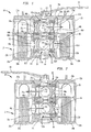
- FIGS. 1 and 2 show a duplex strainer 10 constructed in accordance with a first embodiment of the present invention.
- the duplex strainer 10 includes a housing 12 having a pair of outer bores 14a, 14b and an intermediate bore 14c positioned between the outer bores 14a, 14b. More particularly, the outer bores 14a, 14b and the intermediate bore 14c, which is delimited by an inner cylindrical wall 16 of the housing 12, are linearly arranged in an axial direction substantially parallel to a longitudinal axis A of the housing 12 (see FIG. 3).
- Strainer baskets 18a, 18b are mounted in the outer bores 14a, 14b, respectively, while caps 20a, 20b are secured to the housing 12 for closing off the outer bores 14a, 14b, respectively, in a liquid-tight manner.
- Upper orifices 22a, 22b and lower orifices 22c, 22d are also provided in the inner wall 16 of the housing 12. More particularly, the upper and lower orifices 22a, 22c are formed in a portion of the inner wall 16 between the outer and intermediate bores 14a, 14c, while the upper and lower orifices 22b, 22d are formed in an opposite portion of the inner wall 16 between the outer and intermediate bores 14b, 14c.
- the housing 12 also includes an inlet 24 (see FIGS.
- the duplex strainer 10 also includes a flow control assembly 30 associated with the intermediate bore 14c of the housing 12.
- the flow control assembly 30 is provided with a cartridge 32 having a cap 20c removably attached to the upper end 26 of the housing 12 and having an aperture 34 extending therethrough.
- the cartridge 32 also includes a cylindrical body 36 depending from the cap 20c and removably positioned in the intermediate bore 14c.
- Upper and lower valve chambers 38a, 38b are formed in the body 36. More particularly, the upper chamber 38a is located above the lower chamber 38b and is divided from same by a divider 40 having an aperture 42 therethrough.
- a bottom hole 44 which communicates with the lower chamber 38b, is formed in a bottom end of the body 36.
- the body 36 is also provided with an upper groove 46a adjacent the cap 20c and a lower groove 46b adjacent the divider 40 for purposes to be discussed hereinafter.
- the body 36 is provided with a pair of upper axial holes 48a, 48b, a pair of lower axial holes 48c, 48d, a pair of upper transverse holes 50a, 50b (see FIGS. 4 and 6) and a pair of lower transverse holes 50c, 50d (see FIGS. 4 and 6).
- the upper axial holes 48a, 48b and the upper transverse holes 50a, 50b are formed in an upper wall portion of the body 36 and thereby communicate with the upper chamber 38a, while the lower axial holes 48c, 48d and the lower transverse holes 50c, 50d are formed in a lower wall portion of the body 36 and thereby communicate with the lower chamber 38b.
- the upper axial holes 48a, 48b oppose one another in the axial direction (i.e., in a direction substantially parallel to the longitudinal axis A of the housing 12). That is, the upper axial holes 48a, 48b are arranged in the body 36 along the axial direction, and, as a result, they are aligned with the upper orifices 22a, 22b, respectively, of the housing 12 (see FIG. 1). Likewise, the lower axial holes 48c, 48d, which are formed directly below the upper axial holes 48a, 48b, respectively, oppose one another in the axial direction and are aligned with the lower orifices 22c, 22d, respectively, of the housing 12 (see FIG. 1).
- the upper transverse holes 50a, 50b also oppose one another in a transverse direction substantially perpendicular to the longitudinal axis A of the housing 12, and, as a result, the upper transverse hole 50a is aligned with the inlet orifice 24a of the inlet 24 (see FIG. 4).
- the lower transverse holes 50c, 50d oppose one another in the transverse direction, and, as a result, the lower transverse hole 50d is aligned with the outlet orifice 28a of the outlet 28 (see FIG. 4).
- the flow control assembly 30 is further provided with an upper ball 52a, which is rotatably mounted in the upper chamber 38a, and a lower ball 52b which is rotatably mounted in the lower chamber 38b.
- the upper and lower balls 52a, 52b which are substantially identical to one another in construction and size, have diameters which are smaller than those of the upper axial holes 48a, 48b and the lower axial holes 48c, 48d, respectively, but which are greater than those of the upper transverse holes 50a, 50b and the lower transverse holes 50c, 50d, respectively.
- the upper ball 52a is adapted to be inserted into the upper chamber 38a through one of the upper axial holes 48a, 48b but not through the upper transverse hole 50a or the upper transverse hole 50b.
- the lower ball 52b is adapted to be inserted into the lower chamber 38b through one of the lower axial holes 48c, 48b but not through the lower transverse hole 50c or the lower transverse hole 50d.
- the transverse holes 50a, 50b and the transverse holes 50c, 50d can be designed so as to allow passage of the upper and lower balls 52a, 52b, respectively, therethrough.
- Each of the upper and lower balls 52a, 52b is provided with a pair of axial openings 54a, 54b, which diametrically oppose one another and which are therefore apart from one another by about 180°, and a transverse opening 54c, which communicates with the axial openings 54a, 54b and which is apart from the axial opening 54a and the axial opening 54b by about 90°.
- each of the upper and lower balls 52a, 52b has an arcuate sealing surface 56, which is located opposite the transverse opening 54c, and upper and lower slots 58a, 58b (see FIGS. 6 and 7) in upper and lower sides thereof.
- the flow control assembly 30 is provided with a pair of upper annular seat members 60a, 60b, a pair of lower annular seat members 60c, 60d, a pair of upper annular seal members 62a, 62b and a pair of lower annular seal members 62c, 62d.
- the upper and lower seat members 60a-60d are made from any suitable materials, such as plastic, polypropylene and polyethylene.
- each of the upper and lower seat members 60a-60d has a cylindrical section 64, a flange 66, which projects from the cylindrical section 64, a plurality of sealing ridges 68, which are located adjacent the flange 66, and a channel 70 which is formed in an outer surface of the cylindrical section 64.
- Each of the cylindrical sections 64 of the upper and lower seat members 60a-60d has a free end 71 located opposite the flange 66 and having a contour substantially corresponding to the contour of a corresponding one of the upper and lower axial openings 48a-48d of the cartridge 32.
- the upper seat members 60a, 60b are mounted in the upper axial holes 48a, 48b, respectively, of the cartridge 32 such that the flanges 66 of the upper seat members 60a, 60b are positioned adjacent the upper ball 52a and such that the sealing ridges 68 of the upper seat members 60a, 60b engage the upper ball 52a in a liquid-tight manner.
- the lower seat members 60c, 60d are mounted in the lower axial holes, 48c, 48d, respectively, of the cartridge 32 such that the flanges 66 of the lower seat members 60c, 60d are positioned adjacent the lower ball 52b and such that the sealing ridges 68 of the lower seat members 60c, 60d engage the lower ball 52b in a liquid-tight manner.
- each of the upper and lower seal members 62a-62d can be made from any materials suitable for performing a sealing function, they are preferably made from flexible (i.e., elastomeric) materials, such as ethylene propylene, elastomer, floro-elastomer and nitrile, for purposes to be discussed hereinafter.
- elastomeric materials such as ethylene propylene, elastomer, floro-elastomer and nitrile, for purposes to be discussed hereinafter.
- each of the upper and lower seal members 62a-62d has an annular sealing projection 72 on one side thereof, a sealing surface 74 on an opposite side thereof and an internal projection 76 formed on an inner annular surface thereof and sized and shaped so as to be received in a corresponding one of the channels 70 of the upper and lower seat member 60a-60d.
- Each of the upper and lower seal members 62a-62d also has an opening 78 therein sized and shaped so as to receive a corresponding one of the cylindrical sections 64 of the upper and lower seat members 60a-60d. More particularly, the upper seal member 62a is positioned in the upper axial hole 48a of the cartridge 32 such that the cylindrical section 64 of the upper seat member 60a is received in the opening 78 of the upper seal member 62a and such that the sealing projection 72 and the sealing surface 74 of the upper seal member 62a engage the flange 66 of the upper seat member 60a and the inner wall 16 of the housing 12 (i.e., a portion of the inner wall 16 around the upper orifice 22a), respectively, in a liquid-tight manner.
- the upper seal member 62b, the lower seal member 62c and the lower seal member 62d are positioned in the upper axial hole 48a, the lower axial hole 48c and the lower axial hole 48d, respectively, of the cartridge 32 in a manner substantially identical to the manner in which the upper seal member 62a is positioned in the upper axial hole 48a of the cartridge 32.
- the upper ball 52a is captured between the upper seat and seal members 60a, 62a and the upper seat and seal members 60b, 62b
- the lower ball 52b is captured between the lower seat and seal members 60c, 62c and the lower seat and seal members 60d, 62d.
- the flow control assembly 30 also includes a lower stem 80 rotatably mounted in the aperture 42 of the divider 40 and having an upper end 80a, which is received in the lower slot 58b of the upper ball 52a, and a lower end 80b received in the upper slot 58a of the lower ball 52b.
- An upper stem 82 is also rotatably mounted in the aperture 34 of the cap 20c of the cartridge 32 and has an upper end 82a, which extends outwardly from the cap 20c, and a lower end 82b received in the upper slot 58a of the upper ball 52a.
- a handle 84 is secured to the upper end 82a of the upper stem 82 and is pivotable between a first position, in which it extends from the upper stem 82 in the axial direction towards the outer bore 14a (see FIGS. 2 and 3), and a second position, in which it extends from the upper stem 82 in the axial direction towards the outer bore 14b (see FIGS. 1 and 3). That is, the handle 84 is pivotable about 180° between its first and second positions. Because the upper and lower balls 52a, 52b are interconnected to the handle 84 via the upper and lower stems 82, 80, they are rotatable in the upper and lower chambers 38a, 38b, respectively, between their first and second positions (see FIGS. 1 and 2) in response to pivoting movement of the handle 84.
- the flow control assembly 30 also includes a pair of upper sealing rings 86a, which are positioned in the aperture 34 of the cap 20c of the cartridge 32 between the cap 20c and the upper stem 82, and an upper annular seal 88a, which is received in the upper groove 46a between the body 36 of the cartridge 32 and the inner wall 16 of the housing 12, for enclosing the open top end of the intermediate bore 14c in a liquid-tight manner.
- Lower sealing rings 86b are also mounted in the aperture 42 of the divider 40 between the divider 40 and the lower stem 80, while a lower annular seal 88b is received in the lower groove 46b between the body 36 and the inner wall 16.
- the lower sealing rings 86b and the lower seal 88b are adapted to seal off the upper chamber 38a from the lower chamber 38b in a liquid-tight manner.
- the flow control assembly 30 is pre-assembled in the manner described above so as to facilitate assembly of the duplex strainer 10. More particularly, with the lower stem 80 properly positioned in the aperture 42 of the divider 40, the upper and lower balls 52a, 52b are inserted into the upper and lower chambers 38a, 38b, respectively, through one of the upper axial holes 48a, 48b and through one of the lower axial holes 48c, 48d, respectively. Next, the upper and lower seat members 60a-60d and the upper and lower seal members 62a-62d are properly mounted in the upper and lower axial holes 48a-48d, respectively. The upper stem 82 is also inserted into the aperture 34 of the cap 20c, while the handle 84 is coupled to the upper stem 82. After its pre-assembly, the flow control assembly 30 is properly mounted in the intermediate bore 14c of the housing 12. That is, the body 36 of the flow control assembly 30 is inserted into the intermediate bore 14c, while the cap 20c is secured to the housing 12.
- the handle 84 In operation, in order to cause liquid to flow through the strainer basket 18b, the handle 84 is pivoted to its second position, thereby rotating the upper and lower balls 52a, 52b to their second positions (see FIG. 1). With reference to FIGS. 1 and 4, when the handle 84 is in its second position, the sealing surfaces 56 of the upper and lower balls 52a, 52b are aligned with the upper and lower axial holes 48a, 48c, respectively, of the cartridge 32 and hence with the upper and lower orifices 22a, 22c, respectively, of the housing 12, thereby blocking off the upper and lower orifices 22a, 22c, respectively, in a liquid-tight manner.
- the axial openings 54a of the upper ball 52a is aligned with the upper transverse hole 50a of the cartridge 32 and hence with the inlet orifice 24a of the inlet 24, while the transverse opening 54c of the upper ball 52a is aligned with the upper axial hole 48b of the cartridge 32 and hence with the upper orifice 22b of the housing 12.
- the axial opening 54b of the lower ball 52b is aligned with the lower transverse hole 50d of the cartridge 32 and hence with the outlet orifice 28a of the outlet 28, while the transverse opening 54c of the lower ball 52b is aligned with the lower axial hole 48d of the cartridge 32 and hence with the lower orifice 22d of the housing 12.
- liquid flows to the outer bore 14b from the inlet 24 through the inlet orifice 24a and the upper transverse hole 50a of the cartridge 32 (as indicated by arrow B in FIG. 4) and then through the upper axial hole 48b of the cartridge 32 and the upper orifice 22b of the housing 12 (as indicated by arrow C in FIG. 1).
- the liquid flows from the outer bore 14b to the outlet 28 through the lower orifice 22d of the housing 12 and the lower axial hole 48d of the cartridge 32 (as indicated by arrow D in FIG. 1) and then through the lower transverse hole 50d of the cartridge 32 and the outlet orifice 28a (as indicated by arrow E in FIG. 4).
- the handle 84 in order to cause liquid to flow through the strainer basket 18a, the handle 84 is pivoted to its first position, thereby rotating the upper and lower balls 52a, 52b to their first positions. More particularly, when the handle 84 is moved to its first position, the sealing surfaces 56 of the upper and lower balls 52a, 52b are aligned with the upper and lower axial holes 48b, 48d, respectively, of the cartridge 32 and hence with the upper and lower orifices 22b, 22d, respectively, of the housing 12 so as to block off the upper and lower orifices 22b, 22d, respectively, in a liquid-tight manner.
- the axial openings 54b of the upper ball 52a is aligned with the upper transverse hole 50a of the cartridge 32 and hence with the inlet orifice 24a of the inlet 24, while the transverse opening 54c of the upper ball 52a is aligned with the axial upper hole 48a of the cartridge 32 and hence with the upper orifice 22a of the housing 12.
- the axial opening 54a of the lower ball 52b is aligned with the lower transverse hole 50d of the cartridge 32 and hence with the outlet orifice 28a of the outlet 28, while the transverse opening 54c of the lower ball 52a is aligned with the lower axial hole 48c of the cartridge 32 and hence the lower orifice 22c of the housing 12.
- liquid flows to the outer bore 14a from the inlet 24 through the inlet orifice 24a and the upper transverse hole 50a of the cartridge 32 and then through the upper axial hole 48a of the cartridge 32 and the upper orifice 22a of the housing 12 (as indicated by arrow F in FIG. 2).
- the liquid flows from the outer bore 14a to the outlet 28 through the lower orifice 22c of the housing 12 and the lower axial hole 48c of the cartridge 32 (as indicated by arrow G in FIG. 2) and then through the lower transverse hole 50d of the cartridge 32 and the outlet orifice 28a.
- the present invention provides numerous advantages over the prior art discussed above.
- the upper and lower balls 52a, 52b and their associated components e.g., the upper and lower seat members 60a-60d and the upper and lower seal members 62a-62d
- the cartridge 32 because of the cartridge 32, installation of the upper and lower balls 52a, 52b in the housing 12 of the duplex strainer 10 is made significantly easy and efficient.
- the flow control assembly 30 is easily removable from the housing 12 of the duplex strainer 12 without disassembling other strainer components, periodic servicing of the flow control assembly 30 (e.g., replacement of the upper and lower seal members 62a-62d) is rendered efficient.
- the upper and lower seal members 62a-62d provide additional advantages. More particularly, because the upper and lower seal members 62a-62d are made from flexible (i.e., elastomeric) materials, when subjected to different fluid pressures, the upper and lower balls 52a, 52b are movable within the chambers 38a, 38b, respectively, of the cartridge 32 so as to promote an enhanced seal between various sealing contacts (i.e., between the sealing surfaces 56 of the upper and lower balls 52a, 52b and the upper seat members 60a, 60b and the lower seat members 60c, 60d, respectively, between the upper and lower seal members 62a-62d and the upper and lower seat members 60a-60d, respectively, and between the upper and lower seal members 62a-62b and the inner wall 16 of the housing 12).
- various sealing contacts i.e., between the sealing surfaces 56 of the upper and lower balls 52a, 52b and the upper seat members 60a, 60b and the lower seat members 60c, 60d, respectively, between the upper and lower seal members
- the upper and lower seal members 62a-62d "float" in the upper and lower axial holes 48a-48d, respectively, of the cartridge 32, making them less susceptible to abrasion and thereby enhancing their operating life, as well as that of the upper and lower seat members 60a-60d.
- the flow control assembly 30 has applications in numerous types of fluid handling apparatus other than a duplex strainer as will be discussed in greater detail hereinafter.
- the upper transverse opening 50b and the lower transverse opening 50c of the cartridge 32 are formed in the body 36 primarily for minimizing the overall weight of the cartridge 32 (i.e., they do not provide a passageway for liquid).
- the upper and lower transverse openings 50b, 50c can be removed or omitted from the cartridge 32 (i.e., they can be plugged).
- the upper and lower balls 52a, 52b described above have a construction identical to one another, each of them can be provided with a different construction depending upon particular application requirements.
- FIGS. 14 and 15 and FIGS. 16-19 depict second and third embodiments, respectively, of the present invention. Elements illustrated in FIGS. 14 and 15 and FIGS. 16-19, which correspond, either identically or substantially, to the elements described above with respect to the embodiment of FIGS. 1-13 have been designated by corresponding reference numerals increased by one hundred and two hundred, respectively. Unless otherwise stated, the embodiments of FIGS. 14-19 are constructed, assembled and operated in the same basic manner as the embodiment of FIGS. 1-13.
- FIGS. 14 and 15 show a diverter valve assembly 110 constructed in accordance with a second embodiment of the present invention. More particularly, the diverter valve assembly 110 includes a housing 112 having a cylindrical bore 114c and an inner wall 116 defining the bore 114c. The housing 112 also includes an inlet 124 and an outlet 128, both of which communicate with the bore 114c. Upper orifices 122a, 122b and lower orifices 122c, 122d are formed in the inner wall 116, communicating with the bore 114c.
- Upper pipes 190a, 190b extend outwardly from the housing 112 and are in communication with the bore 114c through the upper orifices 122a, 122b, respectively, while lower pipes 190c, 190d extend outwardly from the housing 112 and are in communication with the bore 114c through the lower orifices 122c, 122d, respectively.
- the upper and lower pipes 190a, 190c are adapted to be coupled to an inlet line 192a and an outlet line 192b, respectively, of liquid conditioning equipment 194a (e.g., a filter), while the upper and lower pipes 190b, 190d are adapted to be coupled to an inlet line 192c and an outlet line 192d, respectively, of another liquid conditioning equipment 194b.
- the diverter valve assembly 110 includes a flow control assembly 130 which is substantially identical to the flow control assembly 30 of the embodiment shown in FIGS. 1-13 in construction and operation. Accordingly, the flow control assembly 130 includes a cartridge 132 having a pair of upper axial holes 148a, 148b, a pair of lower axial holes 148c, 148d, a pair of upper transverse holes (not shown) and a pair of lower transverse holes (not shown).
- the flow control assembly 130 also includes upper and lower balls 152a, 152b mounted in upper and lower valve chambers 138a, 138b, respectively, of the cartridge 132.
- a handle 184 is pivotally mounted on the cartridge 132 for rotating the upper and lower balls 152a, 152b. More particularly, the handle 184 is pivotable between its first and second positions.
- the handle 184 is moved to its first position, liquid flows from the inlet 124 to the liquid conditioning equipment 194a through the inlet line 192a and then flows to the outlet 128 through the outlet line 192b.
- the handle 184 is moved to its second position, liquid flows from the inlet 124 to the liquid conditioning equipment 194b through the inlet line 192c and then flows to the outlet 128 through the outlet line 192d.
- FIGS. 16-19 show a duplex strainer 210 constructed in accordance with a third embodiment of the present invention.
- the duplex strainer 210 is substantially identical to the duplex strainer of the embodiment shown in FIGS. 1-13 in construction and operation, except as described hereinafter.
- the duplex strainer 210 has a housing 212 having outer bores 214a, 214b and an intermediate bore 214c.
- the housing 212 which includes an inner wall 216 defining the intermediate bore 214c, is provided with upper orifices 222a, 222b and lower orifices 222c, 222d, all of which are formed in the inner wall 216 and communicate with the intermediate bore 214c.
- An inlet 224 has an inlet orifice 224a formed in the inner wall 216.
- An outlet orifice 228a is formed adjacent a bottom end of the intermediate bore 214c for communication with an outlet 228 of the housing 212.
- the duplex strainer 210 also includes a flow control assembly 230 having a cartridge 232 which is substantially identical to the cartridge 32 of the embodiment of FIGS. 1-13 in construction. Accordingly, the cartridge 232 is provided with an upper valve chamber 238a and a lower valve chamber 238b. The cartridge 232 also has a pair of upper axial holes 248a, 248b, a pair of lower axial holes 248c, 248d, a pair of lower transverse holes 248c, 248d and a pair of lower transverse holes 250c, 250d. A bottom hole 244 is formed in a bottom end of the cartridge 232, communicating with the outlet orifice 228a of the housing 212.
- upper and lower balls 252a, 252b are mounted in the upper and lower chambers 238a, 238b, respectively, of the cartridge 232. More particularly, each of the upper and lower balls 252a, 252b has a pair of openings 254a, 254b which communicate with each other and which are oriented from one another by about 90° (i.e., the opening 254a lies in a plane that is substantially normal to the plane in which the opening 254b lies). Each of the upper and lower balls 252a, 252b also has a pair of arcuate sealing surfaces 256a, 256b formed thereon opposite the openings 254a, 254b, respectively.
- An opening 254c is formed in a lower surface of the lower ball 252b, communicating with the openings 254a, 254b of same.
- the opening 254c of the lower ball 252b is oriented about 90° relative to the openings 254a, 254b of the lower ball 252b.
- the lower ball 252b is mounted in the lower chamber 238b in such a manner that the opening 254c of the lower ball 252b is constantly aligned with the bottom hole 244 of the cartridge 232.
- a handle 284 is pivotally mounted on the cartridge 232 for rotating the upper and lower balls 252a, 252b. More particularly, the handle 284 is pivotable about 90° between its first position (indicated by a broken line representation of the handle 284 in FIG. 16) and its second position (indicated by a solid line representation of the handle 284 in FIG. 16) so as to rotate the upper and lower balls 252a, 252b between their first and second positions.
- the openings 254a, 254b of the upper ball 252a are aligned with the inlet orifice 224a and the upper orifice 222b, respectively, of the housing 212 (see FIG.
- the openings 254a, 254b of the upper ball 252a are aligned with the upper orifice 222a and the inlet orifice 224a, respectively, of the housing 212, while the sealing surface 256a of the upper ball 252a is aligned with the upper orifice 222b and thereby obstructs same in a liquid-tight manner.
- the opening 254a of the lower ball 252b is aligned with the lower orifice 222c of the housing 212, while the sealing surface 256a of the lower ball 252b is aligned with the lower orifice 222d and thereby obstructs same in a liquid-tight manner.
- liquid enters the housing 212 through the inlet orifice 224a and then flows to the outer bore 214a through the openings 254b, 254a of the upper ball 252a and through the upper axial hole 248a of the cartridge 232 and the upper orifice 222a of the housing 212.
- the liquid flows to the intermediate bore 214c from the outer bore 214a through the lower orifice 222c of the housing 212 and the lower axial hole 248c of the cartridge 232 and then flows to the outlet 228 through the openings 254a, 254c of the lower ball 252b and through the bottom hole 244 of the cartridge 232 and the outlet orifice 228a of the housing 212.
Landscapes
- Chemical & Material Sciences (AREA)
- Chemical Kinetics & Catalysis (AREA)
- Engineering & Computer Science (AREA)
- General Engineering & Computer Science (AREA)
- Mechanical Engineering (AREA)
- Taps Or Cocks (AREA)
- Multiple-Way Valves (AREA)
- Control Of Non-Electrical Variables (AREA)
Abstract
Description
Claims (9)
- A fluid handling apparatus (10) with a housing (12) having a hollow (14c) therein, said housing (12) having a primary fluid inlet (24a) and a primary fluid outlet (28a), characterized in that said housing (12) has a first intermediate outlet (22c), a first intermediate inlet (22a), a second intermediate outlet (22d) and a second intermediate inlet (22b), each communicating with said hollow (14c), said hollow (14c) having substantially parallel opposing longitudinal wall surfaces (16) and a flow control assembly (30) slidably and removably insertable therein, said flow control assembly (30) including a cartridge (32) having a first chamber (38a) and a second chamber (38b) separated by a dividing wall (40), said cartridge (32) having a valve device (52a,52b) extending therein and rotatable therein, a first portion (52a) of said valve device (52a, 52b) positioned within said first chamber (38a) and a second portion (52b) of said valve device (52a,52b) positioned within said second chamber (38b), said first chamber (38a) having an inlet opening (50a) communicating with said primary fluid inlet (24a), said second chamber (38b) having an outlet opening (50d) communicating with said primary fluid outlet (28a), said first chamber (38a) having first and second intervening outlets (48a,48b) communicating with said first and second intermediate inlets (22a,22b) of said housing, respectively, said second chamber (38b) having first and second intervening inlets (48c,48d) communicating with said first and second intermediate outlets (22c,22d) of said housing (12), respectively, said first portion (52a) of said valve device (52a,52b) having a first fluid passage (54c) therethrough communicating with said inlet opening (50a) of said first chamber (38a) and said first intervening outlet (48a) in a first position of said valve device (52a,52b) and communicating with said inlet opening (50a) of said first chamber (38a) and said second intervening outlet (48b) in a second position of said valve device (52a,52b), said second portion (52b) of said valve device (52a,52b) having a second fluid passage (54c) therethrough communicating with said first intervening inlet (48c) and said outlet opening (50d) of said second chamber (38b) in said first position of said valve device (52a,52b) and communicating with said second intervening inlet (48d) and said outlet opening (50d) of said second chamber (38b) in said second position of said valve device (52a, 52b).
- The fluid handling apparatus (10) of Claim 1, further characterized by a plurality of generally tubular seals (60a,60b,60c,60d), each interposed between and effecting a liquid-tight seal between said valve device (52a,52b) and a surface of said hollow (14c) peripheral to an associated one of said first and second intermediate inlets and outlets (22a,22b,22c,22d), with an interior conduit of each of said seals (60a,60b,60c,60d) permitting a flow of fluid therethrough.
- The fluid handling apparatus (10) of Claim 2, characterized in that said hollow (14c) is generally cylindrical and in that each of said tubular seals (60a,60b,60c,60d) has a concave seat (68) at one end for slidably and sealingly contacting said valve device (52a,52b) and a convex end (71) mating with the inner curvature of said hollow (14c).
- The fluid handling apparatus of Claim 3, characterized in that each of said seals (60a,60b,60c,60d) is composite, a first portion (60a,60b, 60c,60d) thereof having said concave seat (68) and a second portion (62a,62b,62c,62d) thereof fitting coaxially over said first portion (60a,60b, 60c,60d) and having said convex end (74).
- The fluid handling apparatus (10) of Claim 3, characterized in that said cartridge (32) has an internally projecting cylinder associated with each of said intervening inlets and outlets (48c,48d;48a,48b), each said cylinder being disposed at right angles to the axis of said cartridge (32) and slidably receiving a corresponding one of said tubular seals (60a,60b,60c,60d) in piston-fashion.
- The fluid handling apparatus (10) of Claim 5, characterized in that said valve device (52a,52b) includes a pair of balls (52a,52b) with fluid passageways (54a,54b,54c) therethrough, a first (52a) of said pair of balls (52a,52b) received within said first chamber (38a) and a second (52b) of said pair of balls (52a,52b) received within said second chamber (38b), each of said pair of balls (52a,52b) having dimensions permitting them to be inserted through at least one of said cylinders, and each of said pair of balls (52a,52b) being retained in said first and second chambers (38a,38b), respectively, by said tubular seals (60a,60b,60c,60d).
- The fluid handling apparatus (10) of Claim 6, characterized in that said fluid passageway (254a,254c) of each of said balls (252a,252b) is L-shaped.
- The fluid handling apparatus (10) of Claim 6, characterized in that said fluid passageway (54a,54b,54c) of each of said balls (52a,52b) is T-shaped.
- The fluid handling apparatus (10) of Claim 1, characterized in that said flow control assembly (30) selectively directs a fluid flow entering said primary fluid inlet (24a) to one side of a duplex strainer (10) prior to exiting said primary fluid outlet (28a).
Applications Claiming Priority (3)
| Application Number | Priority Date | Filing Date | Title |
|---|---|---|---|
| US277912 | 1999-03-29 | ||
| US09/277,912 US6197195B1 (en) | 1999-03-29 | 1999-03-29 | Fluid handling apparatus and flow control assembly therefor |
| PCT/US2000/008238 WO2000057987A1 (en) | 1999-03-29 | 2000-03-28 | Fluid handling apparatus and flow control assembly therefor |
Publications (4)
| Publication Number | Publication Date |
|---|---|
| EP1189672A1 EP1189672A1 (en) | 2002-03-27 |
| EP1189672A4 EP1189672A4 (en) | 2004-08-04 |
| EP1189672B1 true EP1189672B1 (en) | 2005-12-28 |
| EP1189672B8 EP1189672B8 (en) | 2006-03-22 |
Family
ID=23062909
Family Applications (1)
| Application Number | Title | Priority Date | Filing Date |
|---|---|---|---|
| EP00919760A Expired - Lifetime EP1189672B8 (en) | 1999-03-29 | 2000-03-28 | Fluid handling apparatus and flow control assembly therefor |
Country Status (5)
| Country | Link |
|---|---|
| US (1) | US6197195B1 (en) |
| EP (1) | EP1189672B8 (en) |
| AT (1) | ATE314130T1 (en) |
| DE (1) | DE60025207T2 (en) |
| WO (1) | WO2000057987A1 (en) |
Cited By (1)
| Publication number | Priority date | Publication date | Assignee | Title |
|---|---|---|---|---|
| US10926205B2 (en) | 2017-06-20 | 2021-02-23 | Eaton Intelligent Power Limited | Cast filter assembly-modular design |
Families Citing this family (35)
| Publication number | Priority date | Publication date | Assignee | Title |
|---|---|---|---|---|
| US6761827B2 (en) | 2001-10-26 | 2004-07-13 | Zodiac Pool Care, Inc. | Method and apparatus for purifying water |
| US7238278B2 (en) * | 2001-10-26 | 2007-07-03 | Zodiac Pool Care, Inc. | Apparatus for purifying water |
| US6982040B2 (en) * | 2003-04-16 | 2006-01-03 | Zodiac Pool Care, Inc. | Method and apparatus for purifying water |
| USD496984S1 (en) | 2003-04-18 | 2004-10-05 | Zodiac Pool Care, Inc. | Water purifier |
| USD503770S1 (en) | 2003-04-25 | 2005-04-05 | Zodiac Pool Care, Inc. | Water purifier |
| DE10325525B4 (en) * | 2003-06-04 | 2013-10-24 | Boll & Kirch Filterbau Gmbh | backwash filter |
| US7211176B2 (en) * | 2004-11-02 | 2007-05-01 | Zodiac Pool Care, Inc. | Replaceable chlorinator electrode assembly |
| US20070187306A1 (en) * | 2005-11-03 | 2007-08-16 | Pecca Jeffrey P | Filter housing and parts therefor |
| US7849877B2 (en) | 2007-03-01 | 2010-12-14 | Zodiac Pool Systems, Inc. | Diverter valve |
| US8118590B1 (en) | 2007-03-09 | 2012-02-21 | Coprecitec, S.L. | Dual fuel vent free gas heater |
| US7766006B1 (en) * | 2007-03-09 | 2010-08-03 | Coprecitec, S.L. | Dual fuel vent free gas heater |
| US8403661B2 (en) | 2007-03-09 | 2013-03-26 | Coprecitec, S.L. | Dual fuel heater |
| US8057219B1 (en) | 2007-03-09 | 2011-11-15 | Coprecitec, S.L. | Dual fuel vent free gas heater |
| US7975720B2 (en) * | 2008-03-25 | 2011-07-12 | Conway Scott T | Ball valve cartridge for use with remote handle |
| US9005328B2 (en) * | 2010-04-30 | 2015-04-14 | Tm Industrial Supply, Inc. | Filter |
| US8899971B2 (en) | 2010-08-20 | 2014-12-02 | Coprecitec, S.L. | Dual fuel gas heater |
| DE102012010895A1 (en) * | 2012-06-01 | 2013-12-05 | Hydac Filtertechnik Gmbh | Filter device for fluids |
| EP2971894B1 (en) * | 2013-03-15 | 2017-05-03 | Flowserve Management Company | Transflow valve with an isolation and switching mechanism for double block and bleed arrangement |
| US9500299B2 (en) * | 2013-07-25 | 2016-11-22 | Schaeffler Technologies AG & Co. KG | Thermal management valve module with isolated flow chambers |
| DE102014208358A1 (en) * | 2014-05-05 | 2015-11-05 | Mahle International Gmbh | switching valve |
| DE102016208354A1 (en) * | 2016-05-13 | 2017-11-16 | Deere & Company | A filter assembly |
| CN107542569B (en) | 2016-06-27 | 2021-05-28 | 舍弗勒技术股份两合公司 | Thermal Management Module |
| JP6772991B2 (en) * | 2016-09-27 | 2020-10-21 | 株式会社デンソー | Valve gear and cooling system |
| US10344883B2 (en) * | 2016-11-02 | 2019-07-09 | Schaeffler Technologies AG & Co. KG | Modular electro-mechanical rotary valve |
| US11679348B2 (en) * | 2017-12-29 | 2023-06-20 | Enercorp Engineered Solutions Inc. | Horizontal sand separator assembly |
| CN108619772A (en) * | 2018-05-22 | 2018-10-09 | 佛山市三水万瑞达环保科技有限公司 | A kind of large flow filter |
| US11346453B2 (en) * | 2019-03-03 | 2022-05-31 | California Controlled Atmosphere | Switching assembly for pressure relief valves |
| US12044320B2 (en) * | 2019-03-03 | 2024-07-23 | California Controlled Atmosphere | Switching assembly for pressure relief valves |
| US11598441B2 (en) * | 2019-12-03 | 2023-03-07 | Schaeffler Technologies AG & Co. KG | Coolant control valve with non-coaxial rotary valve bodies |
| US11306954B2 (en) * | 2020-02-13 | 2022-04-19 | Emerson Electric Co. | System for fluid pump down using valves |
| CN113280152B (en) * | 2020-02-19 | 2025-12-16 | 伊利诺斯工具制品有限公司 | Valve |
| US11391383B2 (en) * | 2020-06-24 | 2022-07-19 | Hamilton Sundstrand Corporation | Drive key for rotating equipment accommodating center line misalignment while minimizing hysteresis |
| CN111779861B (en) * | 2020-07-27 | 2024-06-25 | 瑞立集团瑞安汽车零部件有限公司 | Steel ball rotary type oil tank switching valve |
| US11781662B2 (en) * | 2021-05-28 | 2023-10-10 | Hanon Systems Efp Deutschland Gmbh | Multi-port rotary actuated valve assembly |
| JP2025069658A (en) * | 2023-10-18 | 2025-05-01 | ワシノ機器株式会社 | Double Strainer |
Family Cites Families (30)
| Publication number | Priority date | Publication date | Assignee | Title |
|---|---|---|---|---|
| US1634086A (en) | 1924-09-13 | 1927-06-28 | Floyd L Swanberg | Strainer |
| US2977969A (en) | 1958-07-30 | 1961-04-04 | William L Weikly | Angle cock or valve for air brake systems |
| US3066909A (en) | 1959-10-26 | 1962-12-04 | Continental Mfg Company | Plug valve |
| US3536295A (en) | 1967-08-23 | 1970-10-27 | Deas Sinkler | Balanced sleeved plug valve or cock |
| US3618781A (en) | 1969-08-22 | 1971-11-09 | Parker Hannifin Corp | Duplex filtering device |
| US3595270A (en) * | 1970-01-20 | 1971-07-27 | Andale Co | Plug valve construction and operating mechanism |
| US3679060A (en) | 1970-09-08 | 1972-07-25 | Xomox Corp | Duplex strainer construction |
| US3757956A (en) | 1972-03-09 | 1973-09-11 | Kinney Eng S P Inc | Twin basket strainer |
| US3900400A (en) | 1974-04-29 | 1975-08-19 | Caterpillar Tractor Co | Dual filter arrangement |
| US3914176A (en) | 1974-05-06 | 1975-10-21 | Clark Equipment Co | Dual filter assembly |
| US3900401A (en) * | 1974-11-04 | 1975-08-19 | Us Navy | Dual filter for lubricating oil |
| US4113228A (en) | 1976-02-02 | 1978-09-12 | Frye James A | Rotary plug valve |
| US4046695A (en) | 1976-06-07 | 1977-09-06 | Tucker John W | Duplex basket strainer arrangement |
| US4274445A (en) | 1979-04-10 | 1981-06-23 | Pall Corporation | Pressure balanced three-way transfer valve |
| FR2476791A1 (en) * | 1980-02-22 | 1981-08-28 | Jgc Corp | CARTRIDGE TYPE VALVE FOR REPLACING THE HEAD AND HEAD OF THE VALVE QUICKLY |
| US4504390A (en) | 1982-07-20 | 1985-03-12 | Peter Steffen | Selectable filter assembly |
| US4467832A (en) | 1982-08-19 | 1984-08-28 | Nippon Air Brake Co., Ltd. | Cock |
| US4496463A (en) | 1983-12-08 | 1985-01-29 | Mueller Steam Specialty, A Division Of Core Industries, Inc. | Duplex strainer |
| US4606820A (en) * | 1984-10-29 | 1986-08-19 | R-P & C Valve, Inc. | Duplex strainer |
| US4615800A (en) | 1985-01-14 | 1986-10-07 | Donaldson Company, Inc. | Duplex filter apparatus |
| US4969994A (en) * | 1987-01-16 | 1990-11-13 | Donaldson Company, Inc. | Seal arrangement for fluid filters and method |
| US4786409A (en) | 1987-04-20 | 1988-11-22 | Parker-Hannifin Corporation | Duplex filter assembly |
| KR900001399A (en) | 1987-07-07 | 1990-02-27 | 노르우드 워커 피이터 | filter |
| DE3889185D1 (en) | 1987-07-17 | 1994-05-26 | Kurt Michael Desch | Central control valve for a water treatment plant. |
| FR2629555B1 (en) | 1988-03-31 | 1990-11-16 | Sogelerg | DIGITAL VALVE |
| CA1329784C (en) | 1989-01-03 | 1994-05-24 | James Pittman | Filtration removal of matter from gas streams, with off-line cleaning of filters |
| DE8907211U1 (en) * | 1989-06-13 | 1989-07-27 | Hydac Filtertechnik GmbH, 6603 Sulzbach | Changeover valve |
| DE4309366C1 (en) * | 1993-03-23 | 1994-04-21 | Thomas Handtmann | Stackable filter holder - with distributor element seal pref. of polyamide, e.g. for sterile filtration of beer |
| SE502695C2 (en) | 1994-04-20 | 1995-12-11 | Vattenfall Utveckling Ab | Screening device for filtration of water to emergency cooling systems in nuclear power plants |
| US5443722A (en) * | 1994-06-01 | 1995-08-22 | Mueller Steam Specialty | Duplex strainer |
-
1999
- 1999-03-29 US US09/277,912 patent/US6197195B1/en not_active Expired - Lifetime
-
2000
- 2000-03-28 EP EP00919760A patent/EP1189672B8/en not_active Expired - Lifetime
- 2000-03-28 WO PCT/US2000/008238 patent/WO2000057987A1/en not_active Ceased
- 2000-03-28 AT AT00919760T patent/ATE314130T1/en not_active IP Right Cessation
- 2000-03-28 DE DE60025207T patent/DE60025207T2/en not_active Expired - Lifetime
Cited By (1)
| Publication number | Priority date | Publication date | Assignee | Title |
|---|---|---|---|---|
| US10926205B2 (en) | 2017-06-20 | 2021-02-23 | Eaton Intelligent Power Limited | Cast filter assembly-modular design |
Also Published As
| Publication number | Publication date |
|---|---|
| DE60025207T2 (en) | 2006-09-07 |
| WO2000057987A1 (en) | 2000-10-05 |
| US6197195B1 (en) | 2001-03-06 |
| EP1189672A4 (en) | 2004-08-04 |
| EP1189672A1 (en) | 2002-03-27 |
| EP1189672B8 (en) | 2006-03-22 |
| DE60025207D1 (en) | 2006-02-02 |
| ATE314130T1 (en) | 2006-01-15 |
Similar Documents
| Publication | Publication Date | Title |
|---|---|---|
| EP1189672B8 (en) | Fluid handling apparatus and flow control assembly therefor | |
| US5355906A (en) | Pressure balanced mixing valve | |
| EP0774605B1 (en) | Multi-way valve and water purifier using the same | |
| US5230366A (en) | Automatic fluid flow control device | |
| JP3811443B2 (en) | Half ball valve | |
| CA2076924C (en) | Integral check, pressure balanced, control valve | |
| EP2625452A1 (en) | Fluid diverting system | |
| CA2139975C (en) | Duplex strainer | |
| EP1337773B1 (en) | Four way valve | |
| US5507314A (en) | Mixer valve having a ball valve element | |
| AU658607B2 (en) | Mixer valve having a ball valve element | |
| CA1244812A (en) | Faucet device with replaceable valve cartridge | |
| EP0859925A4 (en) | A ball valve cartridge for a mixing valve | |
| US10612689B2 (en) | Manifold for dispensing units | |
| AU692942B2 (en) | An improved ball valve faucet | |
| CA1186975A (en) | Zero internal pressure cartridge | |
| US4832083A (en) | Valve apparatus | |
| JPH09144913A (en) | Multi-way valve, water purifier and fluid distribution and mixing method | |
| CN216677316U (en) | Tap water purifier | |
| US6662668B2 (en) | Fluid flow rate selector | |
| US20070051335A1 (en) | Plug valve with lubrication means | |
| KR20040011775A (en) | Ball valve | |
| WO1999066236A1 (en) | Pivoting gate valve | |
| ZA200106176B (en) | Valve housing. |
Legal Events
| Date | Code | Title | Description |
|---|---|---|---|
| PUAI | Public reference made under article 153(3) epc to a published international application that has entered the european phase |
Free format text: ORIGINAL CODE: 0009012 |
|
| 17P | Request for examination filed |
Effective date: 20011022 |
|
| AK | Designated contracting states |
Kind code of ref document: A1 Designated state(s): AT BE CH CY DE DK ES FI FR GB GR IE IT LI LU MC NL PT SE |
|
| A4 | Supplementary search report drawn up and despatched |
Effective date: 20040621 |
|
| RIC1 | Information provided on ipc code assigned before grant |
Ipc: 7B 01D 35/12 A Ipc: 7F 16K 11/087 B |
|
| RAP1 | Party data changed (applicant data changed or rights of an application transferred) |
Owner name: HAYWARD FILTRATION, LLC |
|
| GRAP | Despatch of communication of intention to grant a patent |
Free format text: ORIGINAL CODE: EPIDOSNIGR1 |
|
| GRAS | Grant fee paid |
Free format text: ORIGINAL CODE: EPIDOSNIGR3 |
|
| GRAA | (expected) grant |
Free format text: ORIGINAL CODE: 0009210 |
|
| AK | Designated contracting states |
Kind code of ref document: B1 Designated state(s): AT BE CH CY DE DK ES FI FR GB GR IE IT LI LU MC NL PT SE |
|
| PG25 | Lapsed in a contracting state [announced via postgrant information from national office to epo] |
Ref country code: AT Free format text: LAPSE BECAUSE OF FAILURE TO SUBMIT A TRANSLATION OF THE DESCRIPTION OR TO PAY THE FEE WITHIN THE PRESCRIBED TIME-LIMIT Effective date: 20051228 Ref country code: CH Free format text: LAPSE BECAUSE OF FAILURE TO SUBMIT A TRANSLATION OF THE DESCRIPTION OR TO PAY THE FEE WITHIN THE PRESCRIBED TIME-LIMIT Effective date: 20051228 Ref country code: FI Free format text: LAPSE BECAUSE OF FAILURE TO SUBMIT A TRANSLATION OF THE DESCRIPTION OR TO PAY THE FEE WITHIN THE PRESCRIBED TIME-LIMIT Effective date: 20051228 Ref country code: LI Free format text: LAPSE BECAUSE OF FAILURE TO SUBMIT A TRANSLATION OF THE DESCRIPTION OR TO PAY THE FEE WITHIN THE PRESCRIBED TIME-LIMIT Effective date: 20051228 |
|
| REG | Reference to a national code |
Ref country code: GB Ref legal event code: FG4D |
|
| REG | Reference to a national code |
Ref country code: CH Ref legal event code: EP |
|
| REG | Reference to a national code |
Ref country code: IE Ref legal event code: FG4D |
|
| RAP2 | Party data changed (patent owner data changed or rights of a patent transferred) |
Owner name: EATON CORPORATION |
|
| REF | Corresponds to: |
Ref document number: 60025207 Country of ref document: DE Date of ref document: 20060202 Kind code of ref document: P |
|
| PG25 | Lapsed in a contracting state [announced via postgrant information from national office to epo] |
Ref country code: DK Free format text: LAPSE BECAUSE OF FAILURE TO SUBMIT A TRANSLATION OF THE DESCRIPTION OR TO PAY THE FEE WITHIN THE PRESCRIBED TIME-LIMIT Effective date: 20060328 Ref country code: SE Free format text: LAPSE BECAUSE OF FAILURE TO SUBMIT A TRANSLATION OF THE DESCRIPTION OR TO PAY THE FEE WITHIN THE PRESCRIBED TIME-LIMIT Effective date: 20060328 Ref country code: IE Free format text: LAPSE BECAUSE OF NON-PAYMENT OF DUE FEES Effective date: 20060328 Ref country code: GR Free format text: LAPSE BECAUSE OF FAILURE TO SUBMIT A TRANSLATION OF THE DESCRIPTION OR TO PAY THE FEE WITHIN THE PRESCRIBED TIME-LIMIT Effective date: 20060328 |
|
| PG25 | Lapsed in a contracting state [announced via postgrant information from national office to epo] |
Ref country code: MC Free format text: LAPSE BECAUSE OF NON-PAYMENT OF DUE FEES Effective date: 20060331 Ref country code: LU Free format text: LAPSE BECAUSE OF NON-PAYMENT OF DUE FEES Effective date: 20060331 |
|
| NLT2 | Nl: modifications (of names), taken from the european patent patent bulletin |
Owner name: EATON CORPORATION Effective date: 20060201 |
|
| PG25 | Lapsed in a contracting state [announced via postgrant information from national office to epo] |
Ref country code: ES Free format text: LAPSE BECAUSE OF FAILURE TO SUBMIT A TRANSLATION OF THE DESCRIPTION OR TO PAY THE FEE WITHIN THE PRESCRIBED TIME-LIMIT Effective date: 20060408 |
|
| PG25 | Lapsed in a contracting state [announced via postgrant information from national office to epo] |
Ref country code: PT Free format text: LAPSE BECAUSE OF FAILURE TO SUBMIT A TRANSLATION OF THE DESCRIPTION OR TO PAY THE FEE WITHIN THE PRESCRIBED TIME-LIMIT Effective date: 20060529 |
|
| REG | Reference to a national code |
Ref country code: CH Ref legal event code: PL |
|
| ET | Fr: translation filed | ||
| PLBE | No opposition filed within time limit |
Free format text: ORIGINAL CODE: 0009261 |
|
| REG | Reference to a national code |
Ref country code: FR Ref legal event code: TP |
|
| STAA | Information on the status of an ep patent application or granted ep patent |
Free format text: STATUS: NO OPPOSITION FILED WITHIN TIME LIMIT |
|
| 26N | No opposition filed |
Effective date: 20060929 |
|
| REG | Reference to a national code |
Ref country code: IE Ref legal event code: MM4A |
|
| PG25 | Lapsed in a contracting state [announced via postgrant information from national office to epo] |
Ref country code: CY Free format text: LAPSE BECAUSE OF FAILURE TO SUBMIT A TRANSLATION OF THE DESCRIPTION OR TO PAY THE FEE WITHIN THE PRESCRIBED TIME-LIMIT Effective date: 20051228 |
|
| REG | Reference to a national code |
Ref country code: FR Ref legal event code: PLFP Year of fee payment: 17 |
|
| REG | Reference to a national code |
Ref country code: FR Ref legal event code: PLFP Year of fee payment: 18 |
|
| REG | Reference to a national code |
Ref country code: FR Ref legal event code: PLFP Year of fee payment: 19 |
|
| REG | Reference to a national code |
Ref country code: DE Ref legal event code: R082 Ref document number: 60025207 Country of ref document: DE Ref country code: DE Ref legal event code: R081 Ref document number: 60025207 Country of ref document: DE Owner name: EATON INTELLIGENT POWER LIMITED, IE Free format text: FORMER OWNER: EATON CORP., CLEVELAND, OHIO, US |
|
| PGFP | Annual fee paid to national office [announced via postgrant information from national office to epo] |
Ref country code: NL Payment date: 20190225 Year of fee payment: 20 |
|
| PGFP | Annual fee paid to national office [announced via postgrant information from national office to epo] |
Ref country code: GB Payment date: 20190222 Year of fee payment: 20 Ref country code: IT Payment date: 20190219 Year of fee payment: 20 Ref country code: DE Payment date: 20190219 Year of fee payment: 20 |
|
| REG | Reference to a national code |
Ref country code: BE Ref legal event code: PD Owner name: EATON INTELLIGENT POWER LIMITED; IE Free format text: DETAILS ASSIGNMENT: CHANGE OF OWNER(S), CESSION; FORMER OWNER NAME: EATON CORPORATION Effective date: 20190311 |
|
| PGFP | Annual fee paid to national office [announced via postgrant information from national office to epo] |
Ref country code: FR Payment date: 20190220 Year of fee payment: 20 Ref country code: BE Payment date: 20190222 Year of fee payment: 20 |
|
| REG | Reference to a national code |
Ref country code: DE Ref legal event code: R071 Ref document number: 60025207 Country of ref document: DE |
|
| REG | Reference to a national code |
Ref country code: NL Ref legal event code: MK Effective date: 20200327 |
|
| REG | Reference to a national code |
Ref country code: GB Ref legal event code: PE20 Expiry date: 20200327 |
|
| PG25 | Lapsed in a contracting state [announced via postgrant information from national office to epo] |
Ref country code: GB Free format text: LAPSE BECAUSE OF EXPIRATION OF PROTECTION Effective date: 20200327 |
|
| REG | Reference to a national code |
Ref country code: BE Ref legal event code: MK Effective date: 20200328 |