EP1189386A2 - Protocol conversion connector of communication network-adapted type and indoor communication network system - Google Patents
Protocol conversion connector of communication network-adapted type and indoor communication network system Download PDFInfo
- Publication number
- EP1189386A2 EP1189386A2 EP01112593A EP01112593A EP1189386A2 EP 1189386 A2 EP1189386 A2 EP 1189386A2 EP 01112593 A EP01112593 A EP 01112593A EP 01112593 A EP01112593 A EP 01112593A EP 1189386 A2 EP1189386 A2 EP 1189386A2
- Authority
- EP
- European Patent Office
- Prior art keywords
- network
- connecting portion
- appliance
- protocol conversion
- control signals
- Prior art date
- Legal status (The legal status is an assumption and is not a legal conclusion. Google has not performed a legal analysis and makes no representation as to the accuracy of the status listed.)
- Withdrawn
Links
Images







Classifications
-
- H—ELECTRICITY
- H04—ELECTRIC COMMUNICATION TECHNIQUE
- H04L—TRANSMISSION OF DIGITAL INFORMATION, e.g. TELEGRAPHIC COMMUNICATION
- H04L69/00—Network arrangements, protocols or services independent of the application payload and not provided for in the other groups of this subclass
- H04L69/08—Protocols for interworking; Protocol conversion
Definitions
- the present invention relates to a newly developed connector with protocol conversion function for transmitted signals and an indoor communication network system. More particularly, the present invention concerns a connector adapted for attaching to a high-functional communication network so constructed that various low-functional network-adapted appliances can be used as object of control of outdoor and indoor communication networks by connecting the high-functional communication network to the low-functional network-adapted appliances and an indoor communication network system so made as to improve the operation or the handling of various network-adapted appliances connected to the indoor communication network.
- Some appliances use dry batteries for keeping the information stored on such volatile memories, however such ones always need dry batteries, in addition in the event that the dry batteries have run down, there would occur the problem of erasing all the information stored on the memories, thus such means is so inconvenient any way.
- the present invention is proposed to make the recent communication network a more pleasant environment.
- a connector of network-adapted type with protocol conversion function is proposed as the present invention, wherein the connector comprises a primary connecting portion to be connected to the communication network laid indoors, a secondary connecting portion to be connected to a network-adapted appliance, a protocol conversion interface to convert the protocol for control signals to be sent and received between the communication network and the network-adapted appliance, and a feeder connecting portion to feed electric power to the network-adapted appliance to be connected to the secondary connecting portion.
- the present invention provides an indoor communication network system to be used by connecting to outside communication networks such as the Internet
- indoor communication system of the present invention comprises a communication network to which a communication server and plural network-adapted appliances, each set an individual communication address, are connected and laid in buildings such as office building, dwelling house, and the like
- each of the network-adapted appliance comprises a memory for temporarily storing user setting information registered individually
- the communication server detects the activation of power to network-adapted appliances connected to the communication network, and is provided with a user setting information storing table for registering and storing user setting information temporarily saved on the memories of the network-adapted appliances, whereby the communication server, when user setting information is written or rewritten on the memory of any one of the network-adapted appliances, receives user setting information from the corresponding network-adapted appliance and stores the information on the table, and further the communication server detects the activation of power to any one of the network-adapted appliances, the communication server reads out the corresponding user setting information registered and stored for the corresponding network-
- the above-mentioned connector with a function of protocol conversion of the present invention involves three preferred embodiments.
- the connector is adapted for use in an indoor communication network such as an information wire laid indoors and includes a primary connecting portion to be connected to information wire and a feeder connecting portion to supply electric power to network-adapted appliances.
- the connector is adapted for use in an indoor communication network such as an power line to which power line carrier signals superimposed control signals and power source are transmitted and includes a primary connecting portion to be connected to the power line and a feeder connecting portion to supply electric power to network-adapted appliances.
- the connector is adapted for use in wireless communication network laid indoors and includes a wireless signal processing unit to be wirelessly connected to a wireless communication server and a feeder connecting portion to supply electric power to network-adapted appliances.
- the system proposed as the present invention includes also three preferred types embodiments, i.e. information wiring network system, power line-carrier indoor information network system, and wireless indoor information network system.
- the indoor communication net work comprises an information wire to which a protocol conversion connectors is attached at a suitable place, whereby when the communication server detects the activation of power to any one of the network-adapted appliances, the communication server reads out and sends out to the information wire the corresponding user setting information registered and stored for the corresponding network-adapted appliance from the user setting information memory to enable the network-adapted appliance to write the user setting information on its device memory.
- the indoor network comprises a power line to which a communication server installed indoors is connected and control signals is transmitted together with electric power, whereby when the communication server detects the activation of power to any one of the network-adapted appliances, the communication server reads out and sends out to the power line the corresponding user setting information registered and stored for the corresponding network-adapted appliance from the user setting information memory to enable the network-adapted appliance to write the user setting information on its device memory.
- the indoor network comprises a wireless communication system in which radio signals are sent and received between a wireless communication server installed indoors and wireless signal processing units provided at a protocol conversion connector for controlling the network-adapted appliances, whereby when the wireless communication server detects the activation of power to any one of the network-adapted appliances, the wireless communication server reads out the corresponding user setting information registered and stored for the corresponding network-adapted appliance from the user setting information memory and converts it into radio signals then sends out it to the wireless communication system to enable the network-adapted appliance to write the user setting information on its device memory.
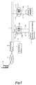
- Fig. 1 is a schematic diagram of a home network system to which a protocol conversion connector of the present invention is applied.
- a communication server 6 is equipped in a dwelling house and information wire for communication network 1 is connected to a primary connecting portion 10a of a protocol conversion connector 10 so that the protocol conversion connector 10 and the communication server 6 can be connected each other in two-way communication.
- Network-adapted appliances 4 such as electrical household appliances are connected to a secondary connecting portion 10b via a control line 2.
- Lighting equipment 5 is connected to a lighting protocol conversion connector 11 provided at a ceiling so as to be able to communicate with the communication server 6 in two-way communication.
- the electrical household appliance 4 and the lighting equipment 5 are also able to execute two-way communication via two protocol conversion connectors 10, 11 and the information wire 1.
- the network-adapted appliance 4 includes air-conditioning equipment, communication equipment, security equipment, and factory facility equipment other than electrical household appliance and lighting equipment.
- the communication server 6 is connected to public line and cable TV line for the Internet L.
- control signals can be transmitted using a communication network such as the Internet L from an outdoor mobile terminal device P to an indoor network-adapted appliances 4, 5.
- a communication network such as the Internet L from an outdoor mobile terminal device P to an indoor network-adapted appliances 4, 5.
- information of the network-adapted appliances 4, 5 can be transmitted to the mobile terminal device P via the Internet L.
- Such a protocol conversion connector 10 can be used by directly connecting an outdoor communication network except for sending and receiving signals to the communication server 6.
- the protocol conversion connector 10 is provided with a power input terminal 10c connected to a power line 3 introduced from an electric distribution board 7 installed indoor, and a feeder connecting portion 10d for feeding electric power to the network-adapted appliance 4 via an electric supply line 3a.
- the information wire 1 is comprised of a private line such as the Ethernet, RS485, and CAN, however it may be wireless such as infra-red radiation or known Bluetooth method.
- a communication network by means of wireless system or power line carrier technology, which are mentioned later, it is constructed by connecting the power line 3, the control line 2, and the electric supply line 3a without using the information wire 1 shown in Fig.1 because the protocol conversion connector can carry the control signals by using a power line.
- two-way high-functional n-to-1 communication is executed via the information wire 1 connected to the primary connecting portion 10a between the communication server 6 connected on the communication network.
- one to one normal communication is executed between the network-adapted appliances 4, 5 connected to the secondary connecting portion 10b.
- Such a protocol conversion connector may be provided with plural secondary connecting portions as described later and 1-to-n normal communication may be executed for plural network-adapted appliances 4, 5.
- communication network connection of low price appliances can be achieved with realistic cost. It is enough that the network-adapted appliances 4, 5 are incorporated with low price communication device capable of normal communication so that whole appliance doesn't become heavy price. Also network-adapted appliances can be used as they are only by replacing a protocol conversion connector when communication method is changed.
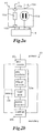
- Fig.2a and Fig.2b show basic construction of the protocol conversion connector.
- the protocol conversion connector 10 shown in Fig.2a shows the most basic construction.
- Such a protocol conversion connector 10 is provided with the primary connecting portion 10a in order to send and receive control signals between the network connected with the communication server 6 and is provided with the secondary connecting portion 10b in order to send and receive control signals between the network-adapted appliance 4.
- the control signals sent and received between the primary connecting portion 10a and the control signals sent and received between the secondary connection portion 10b are constructed so as to be communicated by converting protocol each other at a protocol conversion interface 10e provided in between.
- the feeder connecting portion 10d for connecting a power source supplied by being connected to the power line 3 to the secondary connecting portion 10b, and feeding electricity to the network-adapted appliance 4 via the electric supply line 3a is provided.
- a feeder connecting portion 10d isn't essential in the present invention.
- the protocol conversion interface 10e includes a device such as pulse transformer, the Ethernet controller, UART microcomputer, and RS232C transceiver in order to convert protocol each other between a primary high-functional communication method (the Ethernet) and a secondary normal communicationmethod (RS232C).
- a primary high-functional communication method the Ethernet
- RS232C secondary normal communicationmethod
- the reference numeral 10i is a memory for storing positional information, described later, and is added if necessary.
- Fig.3a and Fig.3b show outside view of the protocol conversion connector.
- Fig.3a is a wall mounted type in which two sets of an outlet type feeder connecting portion 10d are correspondingly provided for modular type secondary connecting portions 10b.
- Fig.3b is a wall mounted type in which a secondary connecting portion 10b' and a feeder connecting portion 10d' are combined and provided. Either type is constructed such that a primary connecting portion (not shown) is connected to a signals line wired in a wall, the network-adapted appliance 4 connects the control line (shown as a reference numeral 3a in Fig.1) introduced therefrom to the modular type secondary connecting portion 10b, 10b', and the control line is inserted into a feeding plug to be connected to the feeder connecting portion 10d, 10d' so as to receive power supply.
- the protocol conversion connector shown in Fig.3c is used for lighting equipment 11.
- a primary connecting portion (not shown), a secondary connecting portion 11b and feeder connecting portion 11d are provided for a conventional hanging type ceiling structure and further a protocol conversion interface is incorporated therein.
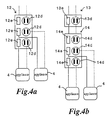
- Fig.4a and Fig.4b show an example how the protocol conversion connector is used.
- the protocol conversion connector 12 shown in Fig.4a is constructed such that three sets of secondary connecting portion, corresponding feeder connecting portions 12d, and protocol conversion interfaces 12e corresponding to them are provided in one body.
- Fig.4b a connector body 14 in which three sets of secondary connecting portions, feeder connecting portions 14d, and protocol conversion interfaces 14e are provided and one protocol conversion connector 13 are connected in series .
- Fig.5 is a schematic diagram of a home network system adapting such a protocol conversion connector.
- the network-adapted appliances 4 (#1-3) are connected to each secondary connecting portion 10b of the protocol conversion connectors 10(#1-3) via control lines 2, and the communication server 6 is connected to the primary connecting portion 10a via the information wire 1.
- Each protocol conversion connectors 10 (#1-3) are provided with a memory (10i in Fig.2b), in which positional information thereof is stored.
- the positional information is set corresponding to the room in which protocol conversion connectors 10(#1) - (#3) are provided, 10(#1) : “living room on the first floor -1", like 10 (#2) : “living room on the first floor-2", 10 (#3) : "kitchen on the first floor” .
- protocol conversion connector 10(#1-3) capable of storing positional information, if the control signals from the network-adapted appliances 4(#1-3) is added with an individual communication address and positional information allotted to each protocol conversion connector 10 (#1-3) and is transmitted to the communication server 6, setting position and operational condition of each network-adapted appliances 4 (#1-3) can be comprehended in the communication server 6.
- connected position (installation location) and operational condition of the appliances 4 can be listed on an operational screen of the communication server 6, as shown in Fig.6a.
- the floor plan of a house can be shown on the screen of the communication server 6 and the communication addresses 21 - 24 allotted to the protocol conversion connector can be shown together with the pictures of the appliances 4 connected to the connectors. In such a case it is recognized at a glance which protocol conversion connector is allotted for what appliance.
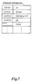
- Fig.7 is a display sample in which detailed information stored in the protocol conversion connector is shown on the screen of the communication server 6.
- allocated communication address 23
- installation location living -1
- kind of network-adapted appliance massaging tool
- operational condition off
- power consumption 789W
- the display screen is switched to the detailed information as shown in Fig.7 and kinds of network-adapted appliance connected to the protocol conversion connector, its on-off condition, attribute information such as power consumption, and the room in which the appliance is installed are shown.
- a communication address of the protocol conversion connector 10 (#1, 2, 3) to be set and modified is specified and transmission request for positional information is sent. Then the designated protocol conversion connector 10 (#1, 2, 3) returns positional information by adding own address and the received positional information is shown on the screen of the communication server 6.
- positional information corresponding to the communication address is rewritten for the designated each protocol conversion connector 10 (#1, 2, 3) by the screen display and is stored in the memory of the protocol conversion connector 10 (#1, 2, 3).
- the protocol conversion connector 10 (#1, 2, 3) which receives positional information in such a way rewrites and revises the already stored positional information into the transmitted positional information.
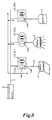
- Fig.8 shows construction of a home network system using a mobile terminal unit as a network-adapted appliance.
- the mobile terminal unit 8 is connected to the secondary connecting portion 10b of one protocol conversion connector 10 (#1) as a network-adapted appliance via the control line 2, the positional information of optional protocol conversion connector 10 (#1, 2, 3) connected to the information wire 1 is designed to be set and modified by operating the mobile terminal unit 8. That is, the positional information stored in the optional protocol conversion connector 10 is read out on the display screen of the mobile terminal unit 8 as mentioned above so as to be set and modified.
- Setting and modifying method of the positional information of the protocol conversion connector 10 isn't limited to the above-mentioned method, for example, the mobile terminal unit 8 may be directly connected to the information wire 1.
- a control switch (not shown) may be provided for each protocol conversion connector 10 (#1, 2, 3) as positional information setting and modifying means and positional information per each protocol conversion connector 10 may be locally set up.
- positional information including communication address of the protocol conversion connector 10 can be set and modified from the communication server 6 or the mobile terminal unit 8.
- Such a protocol conversion connector having additional functions is included in the present invention as another embodiments.
- Fig.9a is a protocol conversion connector 15 having a power cut-off circuit 10f.
- a type can cut off electric source to be supplied to the network-adapted appliance 4 by operating the cut-off circuit 10f when power cut-off is requested by the communication server 6 and so on. Therefore, power saving can be achieved by cutting off standby power and further, the power can be shut off urgently even if a malfunction is occurred in the connected network-adapted appliance 4 and dangerous situation is happened wherein the appliance can't stop by itself.
- Fig.9b shows a protocol conversion connector 16 used for power line carrier system in which power line carrier signals are supplied from a power line.
- Such a protocol conversion connector 16 is provided with a control information/power sending and receiving circuit 10g in which the control information containing communication address and power source are separated from the power line carrier signals transmitted via the power supply line 1a, and the control signals sent from the network-adapted appliance 4 via the secondary connecting portion 10b are superimposed on the power line carrier signals transmitted to the power supply line 1a and are returned.
- the individual communication address is set for the protocol conversion interface 10e and protocol conversion of the control signals is executed in order to be able to send and receive the control signals between the network-adapted appliance 4 connected to the secondary connecting portion 10b and the communication server 6 connected to the power supply line 1a.
- Electric power separated by the control information/power sending and receiving circuit 10g is dispatched to the network-adapted appliance 4 via the feeder connecting portion 10d.
- the reference numeral 10h is power conversion circuit and is described later.
- Fig.9c shows a protocol conversion connector 17 used for a wireless communication network system.
- the protocol conversion connector 17 is adapted for a wireless communication network which sends and receives radio signals superimposed with the control signals between a wireless communication server (not shown) laid indoor.
- a wireless signal processing unit 18 with an antenna 18a for sending and receiving the radio signals superimposed with the control signals between the wireless communication server is constructed.
- the network-adapted appliance 4 is connected to the secondary connecting portion 10b via the control line 2, an individual communication address is set for the protocol conversion interface 10e, and protocol conversion is executed in order to make possible to send and receive the control signals between the network-adapted appliance 4 connected to the secondary connecting portion 10b and the wireless communication server.
- the feeder connecting portion 10d is constructed so as to supply power source dispatched via the power line 3 to the network-adapted appliance 4 connected to the secondary connecting portion 10b via the power supply line 3a.
- the block indicated as a reference numeral 10h in Fig.9b and Fig.9c is a power source conversion circuit 10h.
- Such a circuit 10h may be constructed so as to have booster function by incorporating a booster circuit, have step-down function by incorporating a step-down circuit, or to have both functions.
- power capacity namely current and/or voltage can be adjusted by providing an adjustment dial for such a power source conversion circuit 10h.
- Fig.10 is an example of construction of an indoor communication network system.
- the indoor communication network system N is constructed such that the communication server 6 having a user setting information storing memory 6a storing a user setting information story table and the network-adapted appliances 4 in which individual communication address is set are connected to the information wire 1 laid in structures such as a building and a house.
- the network-adapted appliance 4 incorporates a communication device utilizing embedded type micro Internet interface so that two-way information transmission can be possible between the communication server 6 and the network-adapted appliances 4 in a house by means of communication protocol used in the Internet.
- the appliances 4 can be remotely controlled from the communication server 6 and the data of the appliances 4 can be collected by the communication server 6. Further, the control signals can be sent and received with an external communication terminal M via a communication network like the Internet L.
- a video player, a massaging tool, and so on are adapted as such network-adapted appliances 4 and current time, recording reservation information, operation mode information can be set by the user so as to facilitate usability.
- a volatile memory 4b device memory for storing the user setting information is provided in each appliance 4.
- the user setting information isn't cleared by standby power requirement when a power switch of the appliance 4 is turned off. However, if a power plug 4a is pulled out of an outlet, power supply is stopped and the information in the memory 4b is cleared.
- the plug 4a is pulled out of the outlet and power is shut off so as to economize standby power and the user setting information is cleared, the information set for the network-adapted appliance 4 is designed to be sent from the communication server 6 when the power is turned on again.
- the present system is characterized in that both power saving function and user-friendliness are consisted.
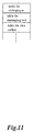
- a user setting information storage table as shown in Fig.11 is provided for the user setting information storing memory 6a of the communication server 6 in order to achieve recovery of user setting information.
- data is transmitted to the communication server 6 from the appliance 4, is stored in the table as user setting information of the appliance 4, and is stored in the memory 6a of the communication server 6.
- the user setting information storage table is divided as shown in Fig.11 corresponding to the communication address of the appliance so as to recover the setting information of each appliance.
- Fig.12 shows flow chart showing basic operation of communication sent and received between the network-adapted appliance 4 and the communication server 6 after the user sets information for the network-adapted appliance 4 and the power is turned off till it is turned on again.
- the network-adapted appliance 4 When the network-adapted appliance 4 is connected to the information wire 1 and the user inputs user setting information such as time-shift reservation information while the power is on, the user setting information is temporally stored in the memory 4b of the network-adapted appliance 4.
- the network-adapted appliance 4 transmits the user setting information to the communication server 6 via the information wire 1.
- the communication server 6 receives the information, it records and stores the sent information in the user setting information storage table (101 - 105).
- the communication server 6 When the communication server 6 receives the notice and detects the network-adapted appliance 4 is turned on, the user setting information registered and stored corresponding to the appliance 4 is read out from the user setting information storage table and distributed to the appliance 4.
- the network-adapted appliance 4 thus being distributed stores the sent user setting information in the memory 4b of the appliance 4 (106 - 113).
- the user setting information stored immediately before the power is shut off is re-registered (recovered) in the memory 4b of the network-adapted appliance 4. Therefore, even if the power of the appliance 4 is turned off, the appliance 4 can be automatically recovered to the condition immediately before the power is turned off when the user uses the appliance.
- the network-adapted appliance 4 may be designed to transmit user setting information periodically other than transmitting the information every time it is set. Otherwise, the information may be transmitted at a timing of shutting off of the power.
- the user setting information is specified according to the function of the network-adapted appliance 4 and includes calendar, timer time, operation setting information to control various schedule such as time-shift reservation information and mode selection setting information (mode selection of massaging tool, switching of radio/tape deck, and so on), and sound volume.
- the current time of the communication server 6 may be transmitted to the network-adapted appliance 4 from the communication server 6 when the network-adapted appliance 4 is turned on and the time may be matched.
- the communication server 6 may detect turning on timing of the network-adapted appliance 4.
- Fig.13 is an example of construction of an indoor communication network system adapting a protocol conversion connector of the present invention.
- the indoor communication network system N1 is constructed with network-adapted appliances 4, the communication server 6 having the user setting information storing memory 6a, and information wire 1 having communication network-adapted protocol conversion connectors 10 in place.
- the above-mentioned protocol conversion connector 10 is used and the feeder connecting portion 10d thereof is connected with the power plug (not shown) of the network-adapted appliance 4 so as to supply power to the appliance 4 introduced from the power line 3.
- the control signals is sent and received to the network-adapted appliance 4 via the information wire 1.
- the appliance 4 can be used as it is without upgrading function because protocol is converted by the protocol conversion connecter 10, thereby the burden of expense is relieved.
- the network-adapted protocol conversion connector 15 having the power cut-off circuit 10f as mentioned above may be used.
- power can be shut off upon requesting power cut off from the communication server 6 because of the function of the power cut-off circuit 10f of the protocol conversion connector 15. Therefore, power saving can be achieved by cutting off standby power without removing the power supply plug from the protocol conversion connector 15.
- power supply can be shut off from the supervising communication server 6.
- power can be shut off by sending control signals following the time schedule prepared in advance from the communication server 6.
- the user setting information is stored in the communication server 6, it isn't cleared even after urgent power shut off of the network adapted appliance 4 and the user can operate the appliance 4 continuously after turning on the power.
- Fig.14 shows basic construction of the power line carrier type indoor communication network system N2.
- the power line carrier signals superimposed with the control signals to the power source having predetermined wave shape is fed to the power supply line 1a from a power line carrier type communication server 6A. Therefore, in case of the power line carrier type indoor communication network in which the primary connecting portion 10a of the above-mentioned protocol conversion connector 16 is adapted for the power supply line 1a, the connector 16 separates the power line carrier signals into control signals and electric power, decodes the control signals, transmits it as control signals to the network-adapted appliance 4 connected to the secondary connecting portion 10b via the protocol conversion interface. Contrary, the control signals sent from the network-adapted appliance 4 are sent by superimposing to the power line carrier signals transmitted to the power line 1a.
- the information wire for control signals isn't required and only the power supply line 1a is connected between the communication server 6A and the protocol conversion connector 16, so that the burden of wire at a time of construction can be removed.
- Fig.15 shows basic construction of wireless type indoor communication network system.
- a wireless communication server 6B having the above-mentioned memory 6a transmits control signals wirelessly to the network-adapted appliance 4.
- the network-adapted appliances 4 can be easily incorporated to the indoor communication network.
- the user setting information of the network-adapted appliance 4 when the user setting information of the network-adapted appliance 4 is set and changed, the user setting information per the network-adapted appliance 4 is stored in the memory 6a of the communication server 6B. Further when the power of the appliance 4 is turned on again, the stored user setting information is read out from the memory 6a and transmitted to the appliance 4. Therefore, even when the power of the appliance 4 is turned on again after the power is turned off, the appliance 4 is immediately returned to its condition before the power is turned off and the user can use the appliance 4 after turning it on without being conscious of the communication server 6B.
- the user doesn't need to operate user setting again after tuning on the power so that it is very convenient. Further, the power plug can be removed out of the outlet so that standby power isn't consumed in vain and power saving effect is increased.
- a network-adapted appliance incorporating low price communication device capable of one to one normal communication can be connected to a communication network having high-functional communication system so that the communication network connection of low price appliances can be achieved with reasonable cost.
- the network-adapted appliance can be continuously used as it is by replacing into the protocol conversion connector corresponding to a new communication protocol even if communication protocol is changed so that maintenance fee can be reduced.
Landscapes
- Engineering & Computer Science (AREA)
- Computer Security & Cryptography (AREA)
- Computer Networks & Wireless Communication (AREA)
- Signal Processing (AREA)
- Cable Transmission Systems, Equalization Of Radio And Reduction Of Echo (AREA)
- Small-Scale Networks (AREA)
- Selective Calling Equipment (AREA)
- Communication Control (AREA)
- Computer And Data Communications (AREA)
Abstract
Description
Network-adapted
It is enough that the network-adapted
Claims (20)
- A communication network-adapted protocol conversion connector adapted for attaching to a communication network laid in buildings such as office building, dwelling house and the like, said connector comprising:a primary connecting portion to be connected to said communication network laid indoors,a secondary connecting portion to be connected to a network-adapted appliance,a protocol conversion interface to convert the protocol for control signals to be sent and received between said communication network and said network-adapted appliance, anda feeder connecting portion to feed electric power to said network-adapted appliance to be connected to said secondary connecting portion.
- The connector of claim 1, wherein said communication network comprises an information wire laid indoors and connected to a communication server, wherein said primary connecting portion is connected to said information wire while said secondary connecting portion is connected to said network-adapted appliance, and wherein said protocol conversion interface is set an individual communication address and converts the protocol for control signals to make it possible to send and receive said control signals between said network-adapted appliance connected to said secondary connecting portion and said communication server connected to said information wire, further wherein said feeder connecting portion supplies said network-adapted appliance with electric power from a power line laid indoors.
- The connector of claim 1, further comprising a control information/ power sending and receiving circuit, wherein said communication network comprises a power line laid indoors and connected to a communication server, for sending power line carrier signals which are superimposed with control signals and power source, wherein said primary connecting portion is connected to said power line while said secondary connecting portion is connected to said network-adapted appliance, and wherein said control information/power sending and receiving circuit separates control signals and power source from said power line carrier signals, sent in through said power line and sends back the control signals, superimposed with said power line carrier signals, sent out from said network-adapted appliance through said secondary connecting portion, further wherein said protocol conversion interface is set an individual communication address, converts the protocol for control signals to make it possible to send and receive the control signals between said network-adapted appliance connected to said secondary connecting portion and said communication server connected to said power line and said feeder connecting portion supplies said network-adapted appliance with electric power separated by said control information/power sending and receiving circuit.
- The connector of claim 1, wherein said communication network comprises a wireless communication network for sending and receiving radio signals superimposed control signals therewith between a wireless communication server installed indoors, wherein said primary connecting portion constitutes a wireless signal processing unit for sending and receiving radio signals superimposed the control signals therewith between said wireless communication server while said secondary connecting portion is connected to said network-adapted appliance, and wherein said protocol conversion interface is set an individual communication address and converts the protocol for control signals to make it possible to send and receive the control signals between said network-adapted appliance connected to said secondary connecting portion and said wireless communication server, further wherein said feeder connecting portion supplies said network-adapted appliance with electric power from a power line laid indoors.
- The connector of claim 2 or 3, further comprising a power cut-off circuit which is controlled by the control signals sent in through said information wire or said power line or by the control signals sent in from said network-adapted appliance connected to said secondary connecting portion.
- The connector of claim 4, further comprising a power cut-off circuit which is controlled by the control signals sent in through said wireless communication server or by control signals sent in from said network-adapted appliance connected to said secondary connecting portion.
- The connector of any one of claim 1 to 3, wherein said protocol conversion connector has a position information storing memory in which positional information contained in the control signals, corresponding to said individual communication address is rewritably saved, said control signals being received at said primary connecting portion through said network or received at said secondary connecting portion from said network-adapted appliance.
- The connector of claim 4, wherein said protocol conversion connector has a position information storing memory in which positional information contained in the control signals, corresponding to said individual communication address is rewritably saved, said control signals being received at said primary connecting portion through said wireless communication server or received at said secondary connecting portion from said network-adapted appliance.
- The connector of one of claim 1 to 4, further comprising a power source conversion circuit which converts the voltage and/or current to be supplied to said network-adapted appliance from said feeder connecting portion.
- An indoor communication network system comprising a communication network to which a communication server and plural network-adapted appliances, each set an individual communication address, are connected and laid in buildings such as office building, dwelling house, or the like, wherein each of said network-adapted appliance comprises a device memory for temporarily storing user setting information registered individually, wherein said communication server detects the activation of power to network-adapted appliances connected to said communication network, and is provided with a user setting information storing memory for registering and storing user setting information temporarily saved on said memories of said network-adapted appliances, whereby said communication server, when user setting information is written or rewritten on said memory of any one of said network-adapted appliances, receives user setting information from the corresponding network-adapted appliance and stores said information on said table, and further said communication server detects the activation of power to any one of the network-adapted appliances, said communication server reads out the corresponding user setting information registered and stored for said corresponding network-adapted appliance from said user setting information memory to enable said network-adapted appliance to write said user setting information on its device memory.
- The system of claim 10, wherein said communication network comprises an information wire to which a protocol conversion connectors is attached at a suitable place, whereby when said communication server detects the activation of power to any one of the network-adapted appliances, said communication server reads out and sends out to said information wire the corresponding user setting information registered and stored for the corresponding network-adapted appliance from said user setting information memory to enable said network-adapted appliance to write said user setting information on its device memory.
- The system of claim 10, wherein said communication network comprises a power line to which a communication server installed indoors is connected and control signals is transmitted together with electric power, whereby when said communication server detects the activation of power to any one of the network-adapted appliances, said communication server reads out and sends out to said power line the corresponding user setting information registered and stored for the corresponding network-adapted appliance from said user setting information memory to enable said network-adapted appliance to write said user setting information on its device memory.
- The system of claim 10, wherein said communication network comprises a wireless communication system in which radio signals are sent and received between a wireless communication server installed indoors and wireless signal processing units provided at a protocol conversion connector for controlling said network-adapted appliances, whereby when said wireless communication server detects the activation of power to any one of the network-adapted appliances, said wireless communication server reads out the corresponding user setting information registered and stored for the corresponding network-adapted appliance from said user setting information memory and converts it into radio signals then sends out it to said wireless communication system to enable said network-adapted appliance to write said user setting information on its device memory.
- The system of claim 11, wherein said information wire is provided at a stable place with a protocol conversion connector, said protocol conversion connector comprising a primary connecting portion to be connected to said communication network laid indoors, a secondary connecting portion to be connected to a network-adapted appliance, a protocol conversion interface to convert the protocol for control signals sent in and received between said communication network and said network-adapted appliances, and a feeder connecting portion to feed electric power laid indoors to said network-adapted appliance to be connected to said secondary connecting portion.
- The system of claim 12, wherein said power line is provided at a stable place with a protocol conversion connector for separating the control signals and power source from said power line carrier signals, said protocol conversion connector comprising a primary connecting portion to be connected to said communication network laid indoors, a secondary connecting portion to be connected to a network-adapted appliance, a protocol conversion interface to convert the protocol for control signals sent and received between a communication server connected to said power line or a communication network laid outdoors and said network-adapted appliance, and a feeder connecting portion to feed electric power to said network-adapted appliance to be connected to said secondary connecting portion.
- The system of claim 13, wherein said communication network comprises wireless network system in which wireless control signals are sent and received between said wireless communication server installed indoors and a wireless protocol conversion connector, said wireless protocol conversion connector comprising a radio signal processing unit for sending and receiving radio signals to and from said wireless communication server, a secondary connecting portion to be connected to a network-adapted appliance, a protocol conversion interface to convert the protocol for control signals sent and received between said wireless communication server and said network-adapted appliances, and a feeder connecting portion, connected to said power line, to feed power to said network-adapted appliance to be connected to said secondary connecting portion.
- The system of claim 11 or 12, wherein said protocol conversion connector further comprises a power cut-off circuit which is controlled by the control signals received at said primary connecting portion or the control signals sent out from said network-adapted appliance connected to said secondary connecting portion.
- The system of claim 13, wherein said wireless protocol conversion connector further comprises a power cut-off circuit which is controlled by the control signals received at said wireless signal processing unit or the control signals sent out from said network-adapted appliance connected to said secondary connecting portion.
- The system of claim 11 or 12, wherein said user setting information temporally saved in said device memory provided at said network-adapted appliance contains setting information for schedule control of said network-adapted appliance.
- The system of claim 13, wherein said user setting information temporally saved in said device memory provided at said network-adapted appliance contains setting information for schedule control of said network-adapted appliance.
Applications Claiming Priority (4)
| Application Number | Priority Date | Filing Date | Title |
|---|---|---|---|
| JP2000262853 | 2000-08-31 | ||
| JP2000262853A JP2002077191A (en) | 2000-08-31 | 2000-08-31 | Communication network coping type power feeding connector |
| JP2000272971A JP2002083119A (en) | 2000-09-08 | 2000-09-08 | Indoor information wiring network system, power line carrier indoor information network system, wireless indoor information network system |
| JP2000272971 | 2000-09-08 |
Publications (2)
| Publication Number | Publication Date |
|---|---|
| EP1189386A2 true EP1189386A2 (en) | 2002-03-20 |
| EP1189386A3 EP1189386A3 (en) | 2003-04-23 |
Family
ID=26598928
Family Applications (1)
| Application Number | Title | Priority Date | Filing Date |
|---|---|---|---|
| EP01112593A Withdrawn EP1189386A3 (en) | 2000-08-31 | 2001-05-23 | Protocol conversion connector of communication network-adapted type and indoor communication network system |
Country Status (5)
| Country | Link |
|---|---|
| US (1) | US20020026532A1 (en) |
| EP (1) | EP1189386A3 (en) |
| KR (1) | KR20020017920A (en) |
| CN (1) | CN1340943A (en) |
| TW (1) | TW515155B (en) |
Cited By (2)
| Publication number | Priority date | Publication date | Assignee | Title |
|---|---|---|---|---|
| DE20315837U1 (en) * | 2003-10-15 | 2005-03-03 | Weidmüller Interface GmbH & Co. KG | Distributor for connecting electrical equipment with multiple power supply |
| EP1489719A3 (en) * | 2003-06-20 | 2007-05-02 | Matsushita Electric Industrial Co., Ltd. | Energy management system, energy management method, and unit for providing information on energy-saving recommended equipment |
Families Citing this family (31)
| Publication number | Priority date | Publication date | Assignee | Title |
|---|---|---|---|---|
| TW200301047A (en) * | 2001-12-14 | 2003-06-16 | Matsushita Electric Industrial Co Ltd | Household appliances, server apparatus, and the communication method with household appliances |
| DE10162986B4 (en) * | 2001-12-20 | 2004-01-15 | Siemens Ag | Connection of networks with different protocols |
| KR100435993B1 (en) * | 2002-04-04 | 2004-06-12 | (주)솔다정보기술 | Electric light control module for home network and control method thereof |
| JP3730599B2 (en) * | 2002-06-27 | 2006-01-05 | 株式会社東芝 | Server apparatus and state control method |
| KR100550524B1 (en) * | 2002-12-06 | 2006-02-10 | 엘지전자 주식회사 | Home Network System and Its Operation Method |
| US7206874B2 (en) * | 2004-01-27 | 2007-04-17 | Inventec Corporation | Status display-enabled connector for a universal asynchronous receiver/transmitter |
| CN1968289B (en) * | 2005-11-18 | 2011-07-06 | 乐金电子(天津)电器有限公司 | Group addressing method for indoor unit of combined air conditioner |
| JP4334534B2 (en) * | 2005-11-29 | 2009-09-30 | 株式会社東芝 | Bridge device and bridge system |
| US7366773B2 (en) * | 2006-01-30 | 2008-04-29 | Dgi Creations, Llc | Alternative communications paths for data sent over power line carrier |
| GB0703752D0 (en) * | 2007-02-27 | 2007-04-04 | Crockford Christopher N J | Control signal transmission |
| JP2010245988A (en) * | 2009-04-09 | 2010-10-28 | Yazaki Corp | Communication address detecting device, control circuit built-in connector, and communication address detecting method |
| US9257842B2 (en) | 2011-02-22 | 2016-02-09 | Asoka Usa Corporation | Set-top-box having a built-in master node that provides an external interface for communication and control in a power-line-based residential communication system |
| US9736789B2 (en) | 2011-02-22 | 2017-08-15 | Asoka Usa Corporation | Power line communication-based local hotspot with wireless power control capability |
| CN102736566A (en) * | 2011-04-01 | 2012-10-17 | 希姆通信息技术(上海)有限公司 | Household control system |
| US20150045977A1 (en) * | 2011-06-17 | 2015-02-12 | Mingyao XIA | Method and apparatus for using plc-based sensor units for communication and streaming media delivery, and for monitoring and control of power usage of connected appliances |
| JP2013106322A (en) * | 2011-11-16 | 2013-05-30 | Panasonic Corp | Radio communication device and radio communication system including the same |
| KR20130096603A (en) | 2012-02-22 | 2013-08-30 | 엘지전자 주식회사 | Building automation and control system and method for operating the same |
| US8768493B2 (en) | 2012-04-25 | 2014-07-01 | Lumenpulse Lighting Inc. | Power line light controller system and method |
| US8848699B2 (en) | 2012-08-08 | 2014-09-30 | Nebula, Inc. | Devices, systems, and methods for distributed monitoring and control of networked server computers |
| WO2014150567A1 (en) * | 2013-03-15 | 2014-09-25 | Asguard Networks, Inc. | Industrial network security |
| KR102108374B1 (en) * | 2013-10-25 | 2020-05-08 | 삼성전자주식회사 | Stroage system and method for analyzing non-signal thereof |
| US9729580B2 (en) | 2014-07-30 | 2017-08-08 | Tempered Networks, Inc. | Performing actions via devices that establish a secure, private network |
| US9729581B1 (en) | 2016-07-01 | 2017-08-08 | Tempered Networks, Inc. | Horizontal switch scalability via load balancing |
| CN108088045B (en) * | 2017-12-18 | 2020-06-23 | 广东美的制冷设备有限公司 | Air conditioner communication mode switching method, air conditioner and readable storage medium |
| US10069726B1 (en) | 2018-03-16 | 2018-09-04 | Tempered Networks, Inc. | Overlay network identity-based relay |
| US10116539B1 (en) | 2018-05-23 | 2018-10-30 | Tempered Networks, Inc. | Multi-link network gateway with monitoring and dynamic failover |
| US10158545B1 (en) | 2018-05-31 | 2018-12-18 | Tempered Networks, Inc. | Monitoring overlay networks |
| US10911418B1 (en) | 2020-06-26 | 2021-02-02 | Tempered Networks, Inc. | Port level policy isolation in overlay networks |
| CN112055027B (en) * | 2020-09-11 | 2023-01-24 | 国网山西省电力公司营销服务中心 | User power consumption information acquisition system based on protocol interface adaptation |
| US11070594B1 (en) | 2020-10-16 | 2021-07-20 | Tempered Networks, Inc. | Applying overlay network policy based on users |
| US10999154B1 (en) | 2020-10-23 | 2021-05-04 | Tempered Networks, Inc. | Relay node management for overlay networks |
Family Cites Families (14)
| Publication number | Priority date | Publication date | Assignee | Title |
|---|---|---|---|---|
| US5068890A (en) * | 1986-10-22 | 1991-11-26 | Nilssen Ole K | Combined signal and electrical power distribution system |
| US5086385A (en) * | 1989-01-31 | 1992-02-04 | Custom Command Systems | Expandable home automation system |
| US5910776A (en) * | 1994-10-24 | 1999-06-08 | Id Technologies, Inc. | Method and apparatus for identifying locating or monitoring equipment or other objects |
| US5867669A (en) * | 1995-07-03 | 1999-02-02 | General Electric Company | Apparatus and method for upgrading communication functions |
| US5828905A (en) * | 1995-11-13 | 1998-10-27 | Mitsubishi Chemical America, Inc. | Adapter and method of connecting devices associated with at least three different protocols |
| DE19731883A1 (en) * | 1997-07-24 | 1999-01-28 | Abb Patent Gmbh | Electrical device with devices for connection to a bus system |
| US6131125A (en) * | 1997-11-14 | 2000-10-10 | Kawasaki Lsi U.S.A., Inc. | Plug-and-play data cable with protocol translation |
| GB2335335A (en) * | 1998-03-13 | 1999-09-15 | Northern Telecom Ltd | Carrying speech-band signals over power lines |
| US6005476A (en) * | 1998-07-24 | 1999-12-21 | Valiulis; Carl | Electronic identification, control, and security system for consumer electronics and the like |
| US6453687B2 (en) * | 2000-01-07 | 2002-09-24 | Robertshaw Controls Company | Refrigeration monitor unit |
| US6934862B2 (en) * | 2000-01-07 | 2005-08-23 | Robertshaw Controls Company | Appliance retrofit monitoring device with a memory storing an electronic signature |
| US6731201B1 (en) * | 2000-02-23 | 2004-05-04 | Robert Shaw Controls Company | Communications module and system |
| US6701192B1 (en) * | 2000-09-13 | 2004-03-02 | Ncr Corporation | Wiring hub for a retail terminal |
| US6972688B2 (en) * | 2003-01-28 | 2005-12-06 | Gateway Inc. | Power supply with modular integrated networking |
-
2001
- 2001-05-15 KR KR1020010026454A patent/KR20020017920A/en not_active Ceased
- 2001-05-15 CN CN01119235A patent/CN1340943A/en active Pending
- 2001-05-18 TW TW090111560A patent/TW515155B/en not_active IP Right Cessation
- 2001-05-23 US US09/863,024 patent/US20020026532A1/en not_active Abandoned
- 2001-05-23 EP EP01112593A patent/EP1189386A3/en not_active Withdrawn
Cited By (3)
| Publication number | Priority date | Publication date | Assignee | Title |
|---|---|---|---|---|
| EP1489719A3 (en) * | 2003-06-20 | 2007-05-02 | Matsushita Electric Industrial Co., Ltd. | Energy management system, energy management method, and unit for providing information on energy-saving recommended equipment |
| DE20315837U1 (en) * | 2003-10-15 | 2005-03-03 | Weidmüller Interface GmbH & Co. KG | Distributor for connecting electrical equipment with multiple power supply |
| US7230820B2 (en) | 2003-10-15 | 2007-06-12 | Weidmüller Interface GmbH & Co.KG | Distributor means for connecting electrical apparatus with a plurality of voltage sources |
Also Published As
| Publication number | Publication date |
|---|---|
| US20020026532A1 (en) | 2002-02-28 |
| EP1189386A3 (en) | 2003-04-23 |
| KR20020017920A (en) | 2002-03-07 |
| TW515155B (en) | 2002-12-21 |
| CN1340943A (en) | 2002-03-20 |
Similar Documents
| Publication | Publication Date | Title |
|---|---|---|
| EP1189386A2 (en) | Protocol conversion connector of communication network-adapted type and indoor communication network system | |
| EP3047494B1 (en) | Easy-install home automation light switch | |
| US6529589B1 (en) | Method and system for monitoring and controlling automation equipment by modem | |
| CN102216916A (en) | Apparatus and method of operation for a remote control system | |
| JP2003530741A (en) | RF home automation system with replicable controller | |
| TWI446676B (en) | Smart power control system | |
| JP2009178006A (en) | Power supply system, outlet | |
| JP2002077191A (en) | Communication network coping type power feeding connector | |
| CN114397824A (en) | A smart home management system based on the Internet of Things | |
| CN101749798B (en) | Air conditioner | |
| JP2002185628A (en) | Wireless power management system and remote control transmitter | |
| JP2009165250A (en) | DC power distribution system | |
| JP2002083119A (en) | Indoor information wiring network system, power line carrier indoor information network system, wireless indoor information network system | |
| JP2000350271A (en) | Power line carrier communication system | |
| JP3209567B2 (en) | Centralized management system | |
| JP2003339086A (en) | Power adapter with power line communication function and installation position recognition method | |
| JP2002164822A (en) | Setting device for power line carrier transmission terminal | |
| CN223205797U (en) | An integrated control device for smart home appliances | |
| CN112904737A (en) | Smart home heating and ventilation integrated control system | |
| CN218820891U (en) | Air conditioner induction power-saving system | |
| JPH11234926A (en) | Adaptor for feeding indoor equipment and distribution board | |
| JP3180428B2 (en) | Wireless home bus system | |
| CN212573059U (en) | Intelligent lighting system | |
| JPH0712959A (en) | Weather sensor device, timer device and electronic device | |
| JP4710595B2 (en) | Wiring system |
Legal Events
| Date | Code | Title | Description |
|---|---|---|---|
| PUAI | Public reference made under article 153(3) epc to a published international application that has entered the european phase |
Free format text: ORIGINAL CODE: 0009012 |
|
| AK | Designated contracting states |
Kind code of ref document: A2 Designated state(s): AT BE CH CY DE DK ES FI FR GB GR IE IT LI LU MC NL PT SE TR |
|
| AX | Request for extension of the european patent |
Free format text: AL;LT;LV;MK;RO;SI |
|
| PUAL | Search report despatched |
Free format text: ORIGINAL CODE: 0009013 |
|
| AK | Designated contracting states |
Designated state(s): AT BE CH CY DE DK ES FI FR GB GR IE IT LI LU MC NL PT SE TR |
|
| AX | Request for extension of the european patent |
Extension state: AL LT LV MK RO SI |
|
| 17P | Request for examination filed |
Effective date: 20030922 |
|
| 17Q | First examination report despatched |
Effective date: 20031021 |
|
| AKX | Designation fees paid |
Designated state(s): DE FR GB |
|
| STAA | Information on the status of an ep patent application or granted ep patent |
Free format text: STATUS: THE APPLICATION HAS BEEN WITHDRAWN |
|
| 18W | Application withdrawn |
Effective date: 20050131 |