EP1189303A2 - Beam forming method and apparatus in a wireless communication system - Google Patents
Beam forming method and apparatus in a wireless communication system Download PDFInfo
- Publication number
- EP1189303A2 EP1189303A2 EP01307786A EP01307786A EP1189303A2 EP 1189303 A2 EP1189303 A2 EP 1189303A2 EP 01307786 A EP01307786 A EP 01307786A EP 01307786 A EP01307786 A EP 01307786A EP 1189303 A2 EP1189303 A2 EP 1189303A2
- Authority
- EP
- European Patent Office
- Prior art keywords
- beam forming
- signal
- signal extraction
- received signals
- forming part
- Prior art date
- Legal status (The legal status is an assumption and is not a legal conclusion. Google has not performed a legal analysis and makes no representation as to the accuracy of the status listed.)
- Withdrawn
Links
Images






Classifications
-
- H—ELECTRICITY
- H01—ELECTRIC ELEMENTS
- H01Q—ANTENNAS, i.e. RADIO AERIALS
- H01Q3/00—Arrangements for changing or varying the orientation or the shape of the directional pattern of the waves radiated from an antenna or antenna system
- H01Q3/26—Arrangements for changing or varying the orientation or the shape of the directional pattern of the waves radiated from an antenna or antenna system varying the relative phase or relative amplitude of energisation between two or more active radiating elements; varying the distribution of energy across a radiating aperture
- H01Q3/2605—Array of radiating elements provided with a feedback control over the element weights, e.g. adaptive arrays
-
- H—ELECTRICITY
- H04—ELECTRIC COMMUNICATION TECHNIQUE
- H04B—TRANSMISSION
- H04B7/00—Radio transmission systems, i.e. using radiation field
- H04B7/02—Diversity systems; Multi-antenna system, i.e. transmission or reception using multiple antennas
- H04B7/04—Diversity systems; Multi-antenna system, i.e. transmission or reception using multiple antennas using two or more spaced independent antennas
- H04B7/08—Diversity systems; Multi-antenna system, i.e. transmission or reception using multiple antennas using two or more spaced independent antennas at the receiving station
- H04B7/0837—Diversity systems; Multi-antenna system, i.e. transmission or reception using multiple antennas using two or more spaced independent antennas at the receiving station using pre-detection combining
- H04B7/0842—Weighted combining
- H04B7/086—Weighted combining using weights depending on external parameters, e.g. direction of arrival [DOA], predetermined weights or beamforming
Definitions
- the present invention relates to a signal extraction method and apparatus in a wireless communication system. More particularly, the present invention relates to a signal extraction method and apparatus used in an interference canceling apparatus and the like which cancels degradation due to co-channel interference in communication channels.
- other route interference canceling apparatus for canceling interference by using two Cassegrain antennas is known as one of the technologies.
- the other route interference canceling apparatus is configured as shown in Fig.1.
- the other route interference canceling apparatus includes send apparatuses 2 and 4 sending a desired signal (D) and an interference signal (I) respectively, antennas 1 and 3 of the send apparatuses, two Cassegrain antennas 5 and 6 directed to a desired wave and an interference wave, an interference canceling apparatus 7, a variable phase shifter 8, a variable attenuator 9, a subtracter 10 and a demodulator 11.
- the Cassegrain antennas are installed such that one of the two Cassegrain antennas is directed to the interference wave and another is directed to the desired wave.
- the Cassegrain antenna 6 is directed to the interference wave direction and the Cassegrain antenna 5 is directed to the desired wave direction. Since the Cassegrain antenna has strong directivity to the front direction, a signal having relatively high S/N ratio (signal-to-noise ratio) can be obtained from each Cassegrain antenna.
- S/N ratio signal-to-noise ratio
- the interference canceling apparatus 7 adjusts the phase and the amplitude of the output signal of the Cassegrain antenna 6 such that it generates opposite phase signal with respect to interference wave which is included in the output signal of the Cassegrain antenna 5. Therefore, interference wave component is removed from the output signal of the Cassegrain antenna 5. That is, according to this other route interference canceling apparatus, interference is removed by subtracting interference wave component from the output signal of the antenna directed to the desired wave by using the output signal of the antenna directed to the interference wave.
- Side lobe canceler is proposed from the viewpoint of suppressing increase of the apparatus size.
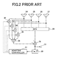
- the side lobe canceler is configured as shown in Fig.2, for example.
- the side lobe canceler includes feed elements 24-27 which form array antennas, a beam forming network (BFN) 28, a subtracter 29, a square circuit 30, an antenna output terminal 31, multipliers 32-35, an adder 36, and an adaptive controller 37.
- BFN beam forming network
- the beam forming network 28 is designed such that a main beam is directed to the desired wave direction and a sub beam can capture the interference wave which is input from a different direction.
- weight coefficient of the sub beam is determined and controlled adaptively by the adaptive controller 37 such that energy of sum of the main beam and the sub beam becomes minimum at the square circuit 30. Accordingly, interference wave incident from the side lobe of the main beam can be suppressed equivalently.
- the other route interference canceling apparatus and the side lobe canceler are effective for a system such as a fixed wireless communication system or a geostationary satellite communication system in which interference wave direction and desired wave direction hardly move.
- the other route interference canceling apparatus and the side lobe canceler can not be applied to a system such as a mobile wireless communication in which the desired wave direction and the interference wave direction change speedily.
- adaptive array is used as a technology for removing interference.
- a desired output signal can be obtained by synthesizing input signals from each (feed) element of the array antenna by assigning weights optimally.
- the adaptive array can be configured as shown in Fig.3, for example.
- This adaptive array includes feed elements 13-16 forming the array antenna, multipliers 17-20, an adder 21, an antenna output signal terminal 22 and an adaptive controller 23.
- input signals from the feed elements 13-16 are weighted by weight coefficient vector output from the adaptive controller 23, and are synthesized by the adder 21 so that desired wave component is extracted. That is, even when an interference wave source or a desired wave source is moved, desired wave can always be extracted by estimating the weight coefficients adaptively in the adaptive controller 23.
- MMSE Minimum Mean Squared Error
- directivity is adaptively controlled such that null of about 40dB is formed in the direction of the interference wave in addition that the beam is directed to the desired wave.
- space area multistage interference canceler is known as a technology for removing interference in which the adaptive arrays are connected forming multistages.
- This space area multistage interference canceler is configured as shown in Fig.4 for example.
- the space area multistage interference canceler includes an input terminal 163 which receives signals from all elements of the array antenna, subtracters 221-226, interference extraction units 201-209, adaptive array units 201-209, adders 178-181, adaptive array antennas 182-184, phase synchronization circuits 185-186, complex multipliers 187-188, discriminators 189-191, and an output terminal 192.
- the interference extraction units 201-209 include adaptive array antennas 182-184, discriminators 189-191, phase synchronization circuits 185-186 and complex multipliers 187-188.
- the interference extraction unit also is a replica generator.
- the interference extraction units 201-203 and the subtracters 221-223 form a first stage
- the adders 178-179, the interference extraction units 204-206 and the subtracters 224-226 form a second stage.
- the same configuration as the second stage is connected in tandem.
- an output signal from the adaptive array antenna is discriminated by the discriminator. Then, convolutional operation is performed on the discriminated signal and impulse response of the transmission line (output from the phase synchronization circuit 185, 186) by the complex multiplier so that a replica signal r and (1) / k,j,p of the interference wave is generated, wherein r indicates the replica signal, (1) indicates the first stage, k indicates time, j indicates element number of antenna and p indicates the pth interference extraction unit.
- interference wave replica generated in this way is subtracted from the received signal from the array antenna element so that an error signal in which effect of the interference wave is eliminated is obtained at a point P.
- interference extraction is performed in the same way as the first stage in which the error signal and the replica signal generated in the first stage are added in each corresponding interference extraction unit. Accordingly, as the stage proceeds, interference signal can be extracted under a condition that effect of interference is small. Thus, relatively good quality demodulation signal can be obtained.
- the adaptive array antennas separate the desired wave and the interference wave by controlling directivity, interference can not be suppressed sufficiently when the desired wave and the interference wave enter the antenna from adjacent directions.
- the separation of the desired wave and the interference wave can be performed accurately by narrowing the beam of the array antenna by widening the interval of elements of the array antenna.
- interference wave increases so that diversity gain decreases.
- the space area multistage interference canceler serves for solving the above-mentioned problem of the adaptive array
- the amount of computation increases in proportion to the product of the number of stages of the processing part which removes the interference wave and the number of interference waves which should be extracted.
- the interference extraction unit includes complex circuits such as the adaptive array and the phase synchronization circuit, the apparatus cost increases.
- the space area multistage interference canceler like the adaptive array, when high-speed signal transmission is performed by using the access technology like CDMA, interference waves increase because delay spread and many multi-path waves intrinsic to the high-speed signal transmission occur. Thus, it is difficult to realize an apparatus which cancels thus increased interference waves by the space area multistage interference canceler.
- a first object of the present invention is to provide a signal extraction method in which interference can be canceled independently of the interval of the elements of the antenna in a wireless communication system which transmits high-speed signals.
- a second object of the present invention is to provide an apparatus which performs signal extraction by using the signal extraction method.
- the above-mentioned first object can be achieved by a signal extraction method in which signals are extracted by using K beam forming parts, wherein K is a natural number equal to or more than 2, and received signals from a plurality of antennas are applied to each beam forming part, the signal extraction method comprising the steps of:
- signal extraction since signal extraction is performed by canceling signal components which are extracted by beam forming parts up to a previous stage beam forming part from received signals which are received by a plurality of antennas. Therefore, signal extraction is performed in a state where interference component is suppressed.
- signal extraction is performed by using the received signals, signal extraction can be performed independently of antenna element interval.
- the present invention can be configured as a signal extraction method in which signals are extracted by using signal extraction parts, wherein received signals from a plurality of antennas are applied to each signal extraction part, the signal extraction parts being connected, each signal extraction part including K beam forming parts, wherein K is a natural number equal to or more than 2, the signal extraction method comprising the steps of:
- a k th beam forming part in a signal extraction part of the second or later stage extracts a k th signal by canceling signal components which are extracted by beam forming parts of the previous stage other than a k th beam forming part of the previous stage from the received signals. Therefore, the later the stage where signal extraction is performed, the more interference component is removed from the k th signal. Therefore, a signal which has good SINR can be extracted.
- the signal extraction method may further includes the steps of:
- signals extracted each beam forming part can be output in descending order of SINR. Therefore, high quality signal demodulation can be performed by using the signals be output in descending order of SINR.
- the above-mentioned second object can be achieved by a signal extraction apparatus which extracts signals from received signals from a plurality of antennas, the signal extraction apparatus comprising:
- a signal extraction apparatus of the present invention can be also configured as a signal extraction apparatus which extracts signals from received signals from a plurality of antennas, the signal extraction apparatus comprising:
- the signal extraction apparatus may further includes:
- the signal estimation apparatus may includes:
- the beam forming part may include an adder, an error detection part, first multipliers to which the received signals are applied, second multipliers to which signals extracted by beam forming parts up to ( k -1)th beam forming part are applied, and an adaptive controller;
- the adaptive controller can estimate and update weight coefficients adaptively so as to cancel signal components which have been extracted from the received signals.
- the beam forming part may include feedforward filters and feedback filters with tap delay line, an adaptive controller and an adder;
- the adaptive control part controls tap coefficients of the feedforward filters and the feedback filters adaptively, effect of delay wave can be decreased when signal extraction is performed in a transmission line having delay spread.
- the adaptive controller may estimate the weight coefficients adaptively so as to cancel, from the received signals, signal components extracted by beam forming parts up to ( k -1) th beam forming part; wherein a dimension extension type algorithm is used for estimation of the weight coefficients, one kind of gain vector is generated, and the gain vector is used for the estimation and update of the weight coefficients.
- the signal extraction apparatus since the dimension extension algorithm which allows high speed convergence is used for estimation and update of weight coefficients used for signal extraction, the estimation and update of weight coefficients is performed speedily. As a result, signal extraction can be performed more speedily.
- a system in which signal extraction is performed according to the signal extraction method of an embodiment of the present invention is configured as shown in Fig.5 for example.
- the signal extraction apparatus 400 receives signals by an array antenna part 300. Then, the signal extraction apparatus 400 performs signal extraction for desired wave and interference wave on the basis of the received signals.
- the signal extraction apparatus 400 is configured as shown in Fig.6 for example.
- Fig.6 shows a first embodiment of the present invention.
- the signal extraction apparatus 400 includes an input terminal 112 which receives signals from every element of the array antenna, beam forming networks (which will be called as BFN) 113-115 and antenna output terminals 116-118.
- BFN beam forming networks
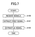
- the signal extraction apparatus 400 first, received signals received by every element of the array antenna are input to each BFN 113-115 (step 100).
- the first BFN(1) 113 assigns weights to the received signals and adds weighted received signals so that a signal d 1 is extracted, and outputs the signal d 1 to the second BFN(2) 114 (step 101).
- the second BFN(2) 114 assigns weights to the signal d 1 and the received signals, and adds the weighted signals such that the signal d 1 is canceled. Then, the second BFN(2) 114 extracts a signal d 2 other than the signal extracted in the first BFN(1) 113. In this way, when extracting a j th signal, the extracted signals d 1 - d j-1 included in the received signals are canceled by using the extracted signals d 1 - d j-1 which are extracted by BNFs up to ( j -1)th BNF, in other words, BFNs from the first BFN to the ( j -1)th BNF (step 102). That is, as signal extraction is performed in more later stage, the signal extraction can be performed in a state in which interference condition is more relieved.
- ratio of interference in the received signals is further decreased. That is, in the last stage BFN(K) 115, since signal extraction is performed in a condition that interference is canceled by using input signals d 1 - d K-1 which have been extracted in antecedent BFNs, the signal d K can be extracted in a high SINR state (Signal to Interference and Noise Ratio) even when it is difficult to detect the received signal.
- SINR state Signal to Interference and Noise Ratio
- the above-mentioned signal extraction apparatus 400 can be configured as shown in Fig.8 as a second embodiment.
- the signal extraction apparatus 400 includes an input terminal 119 which receives signals from all array antennas, an SINR estimation part 120 which estimates SINR of a signal output from each SINR, BFN(1) 121 - BFN(K) 124, a matrix switch circuit 125, antenna output terminals 126-128.
- Each of the BFN(1) 121 - BFN(K) 124 synthesizes signals received by each array antenna weight assigning weight to each of the signals and add the weighted signals, so as to extract a signal ⁇ 1 , ⁇ 1 , ..., ⁇ K which is the desired wave or the interference wave.
- the SINR estimation part 120 estimates SINR of output of each BFN 121 -124, judges from which BNF signal should be extracted first, and generates estimation information for sorting the BFNs in descending order of SINR. In addition, the SINR estimation part 120 outputs the estimation information to each BFN 121 - 124 and the matrix switch circuit 125.
- the BFNs 121 - 124 are logically sorted in descending order of SINR on the basis of the estimation information output by the SINR estimation part 120, where broken lines in Fig.8 indicate the estimation information. Then, the signals ⁇ 1 , ⁇ 1 , ..., ⁇ K are extracted.
- the matrix switch 125 sorts the signals ⁇ 1 , ⁇ 1 , ,..., ⁇ K on the basis of the estimation information from the SINR estimation part 120 so as to output final signals d 1 , d 2 , ..., d K to terminals 126 - 128.
- the signal extraction apparatus 400 extracts the signals d 1 , d 2 , ..., d K which have high SINR sequentially on the basis of estimation information from the SINR estimation part 120, signals having higher quality can be demodulated as a whole.
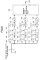
- the SINR estimation part 120 can be configured as shown in Fig.9 for example.
- the SINR(j+1) estimation part includes an input terminal 129 for receiving signals from all antenna elements, BFNs 130 - 132, terminals 164 - 166, 168-170, 172 - 174 for receiving signal sequence extracted by BFNs up to j th BFN, terminals 167, 171 and 175 for receiving candidate signal to be extracted by ( j +1)th BFN, subtracters 133 - 135, square circuits 136-138, a minimum state estimation part 139 for detecting a state of a BFN which outputs a minimum value, and an output terminal 140 of the minimum state estimation part.
- the SINR(j+1) estimation part corresponds to the BFN which extracts the ( j +1)th signal.
- Interference wave or desired wave which is extracted by signals up to j th signal is determined by a previous stage SINR(j).
- signals extracted up to j th are input to the input terminals 164-166, 168-170 and 172-174.
- the received signals are input to each BFN 130-132 simultaneously.
- each BFN 130-132 weights are assigned to signals up to the j th and the weighted signals are added so that added output signal is obtained.
- SINR(j+1) estimation part subtraction is performed between the added output signal and the candidate signal in each subtracter 133-135, the candidate signal being a known training signal 167, 171, 175 for example.
- Euclidean error is estimated by performing square operation on the subtraction result in the square circuit.
- estimation values of Euclidean error are input to the minimum state estimation part 139 so that minimum value of the Euclidean error for candidate values is detected.
- a candidate signal by which the minimum value of the Euclidean error is obtained is regarded as the ( j +1)th signal, and is output.
- estimation of weight coefficients used for weighing and adding is performed for each candidate signal independently. Therefore, for each candidate signal, the weight coefficients are estimated such that SINR becomes maximum when the candidate signal is extracted. As a result, candidate sequence and weight coefficients in which SINR is the best among candidates are determined.
- the order in which the interference wave and the desired wave are extracted is determined by cascading SINRs and sending estimation result information of an SINR to a next SINR estimation part (for example, j+1) one after another.
- Each of the BFN(1) 121 - BFN(K) 124 can be configured as shown in Fig.10 for example. Since the configuration for the BFN(1) 121 - BFN(K) 124 is the same each other, a j th BFN which is indicated by BFN(j) will be described.
- the BFN(j) includes input terminals 143-146 for receiving signals from all elements of the array antenna, multipliers 147-150, 153-155, output terminals 157-159 of the BFN(1) - BFN(j-1), an adder 151, an output terminal 152, a discriminator 160, a switch 161, a training signal input terminal 156, a subtracter (error detection part ) 162 and an adaptive controller 195.
- the BFN(j) receives signals 143-146 from all elements of the array antenna, the BFN(j) weights the signals by using weight coefficients determined in the adaptive controller 195.
- signals extracted from BFN(1) - BFN(j-1) are weighted by using the weight coefficients and added so that the discriminator receives the added output signals.
- the discriminator 160 When the added output signals are input to the discriminator 160, the signals are discriminated and the result is output to the switch 161.
- the discriminator when the received signals from the antenna are in training interval which is inserted into a header of a packet and the like, a training signal is input from the training signal input terminal 156 into the subtracter 162 by the switch 161.
- the switch 161 When the discriminator 160 detects that receive data is in training interval, the switch 161 outputs the training signal. On the other hand, when the discriminator 160 detects that receive data is in information data interval, the switch 161 outputs the signal which is discriminated by the discriminator 160 to the subtracter 162.
- the subtracter 162 obtains difference between the output signal of the switch 161 and the added output signal, and generates error signal and inputs the error signal to the adaptive controller 195.
- the adaptive controller 195 For extracting j th signal d j , the adaptive controller 195 performs adaptive control for weight coefficients such that signals extracted by BFNs up to ( j -1)th BFN are canceled from the received signals on the basis of the received signals from the array antenna, the error signal and the input signals to the BFN(j).
- a high speed algorithm which allows high speed convergence is used, for example, a dimension extension algorithm is used.
- the dimension extension algorithm since solution of least square is obtained sequentially in the same way as the RLS (Recursive Least Squares) adaptive algorithm, the dimension extension algorithm converges as speedily as the RLS algorithm.
- the amount of computation increases in proportion to square of the length of register for gaining the gain vector when using an adaptive algorithm such as RLS.
- the gain vector can be calculated in proportion to the length of register.
- gain vector is used for updating the weight coefficient vector. For example, when BFN(j-1) extracts signal d j-1 , the gain vector of weight coefficients is updated such that the signal d j-1 is canceled in BFN(j-1). By performing such process repeatedly in BFN(2) - BFN(K), weight coefficient vectors up to BFN(K-1) are updated.
- every gain vector can be obtained by performing dimension extension process of one system gain vector. Therefore, the weight coefficients can be estimated with low amount of computation and speedily. As a result, signal extraction can be performed speedily in each BFN.
- the estimation of the weight coefficients can be performed by an equation (1) for example.
- W opt,k E [ X k,j X H k,j ] - 1 E [ d * k,j X k,j ]
- X k,j indicates a signal input to the adaptive controller 195, that is, an input vector.
- the input vector X k,j in the equation (1) is provided by an equation (2).
- X k,j [ r k ,1..., r k,N , d k ,1..., d k,j -1 ] T
- r k,j indicates an input signal from an ith element of the array antenna
- numerical subscript H represents Hermite transpose
- * indicates complex conjugate
- E [ ⁇ ] indicates set mean
- ( ⁇ ) -1 indicates inverse matrix.
- Optimum weight coefficients can be obtained by replacing the set mean of the equation (1) with time mean by using ergodic theorem. That is, the coefficients are obtained by performing time mean process and inverse matrix operation.
- the inverse matrix operation for example, in array antennas to which L signals are received simultaneously, L ⁇ L inverse matrix operation is required in which the amount of computation increases in proportion to the cube of the dimension.
- Estimation operation of the weight coefficients of the equation (1) is performed according to a high speed algorithm by which the estimation can be performed with small amount of computation, for example, dimension extension type Kalman algorithm which uses the dimension extension high speed algorithm.
- the optimized weight coefficient W k,j is calculated according to following equations (3)-(13).
- ⁇ N + j ( k ) A H N + j ( k -1)
- X N + j ( k ) e N+j ( k ) A H N+j ( k )
- X N+j ( k ) ⁇ F N+j ( k -1) + ⁇ N + j ( k ) e * N + j ( k )
- b N+j ( k ) C H N+j ( k- 1)
- the input vector X N +j ( k ) A H N + j ( k -1)
- N+j dimension vector as indicated by the following equations.
- a N + j ( k ) [1, a k, 1 ?? a k,N + j -1 ] T
- C N + j ( k ) [ c k, 1 ?? c k,N + j -1 ,1] T
- Each of the equations (3) ⁇ (13) is formed by a vector or a scalar in which a subscript indicates the dimension. " k " as the subscript or which is parentherized indicatd time, and " ⁇ " indicates forgetting coefficient which is incorporated in order to follow variation of a transmission line.
- the aquation (12) ⁇ j ( k ) d k,j - W H k -1, j X k,j indicated an error signal from the signal d k, j which is extracted by j th BFN(j). Therefore, the optimized weight coefficient W k, j of the equation (13) can be obtained as the sum of j th weight coefficient W k-1, j at a time of k -1, the gain vector K N+j-1 ( k ) and complex conjugate ⁇ * ( k ) of the error signal obtained by the equation (12).
- the gain vetor K N+j-1 ( k ) indicates direction and size of the signal.
- a dimension extension type FTF (Fast Transversal Filter) algorithm can be used as the high speed algorithm which uses the dimension extension high speed algorithm.
- Feedforward filters and feedback filters are provided in a BFN in which signal extraction is performed according to the FTF algorithm.
- delay wave component can be removed from received signals of the antenna by the filters, signal extraction can be performed while performing delay cancellation for high speed transmission.
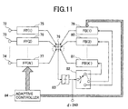
- the BFN using the FTF algorithm is configured as shown in Fig.11 for example.
- the BFN includes input terminals 72 ⁇ 74 receiving signals from all elements of the array antenna, delay line filters with taps 75 ⁇ 77 and 79 ⁇ 81, an adder 78, a discriminator 83, a switch 82 and an adaptive controller 84.
- the delay line filters with taps 75 ⁇ 77 indicate feedforward filters
- delay line filters with taps 79 ⁇ 81 indicate feedback filters.
- the adaptive controller 84 controls tap coefficients of the delay line filters with taps.
- the received signals from the array antenna are synthesized via feedforward filters 75 ⁇ 77.
- the synthesized signal passes through the discriminator 83.
- discrimination signal d i is output from the output terminal 240.
- the discrimination signal d i is supplied to the discriminator 83 via the feedback filters 79 ⁇ 81.
- the discrimination signal d i is input to a register and is shifted.
- the discrimination signal is input to the feedback filters 79 ⁇ 81 while the discrimination signal being switched by the switch 82.
- the discrimination signal also can be input to the feedback filters serially.
- the estimation of the weight coefficients in the BFN is performed according to the dimension extension type FTF algorithm.
- the input vector is defined by the following equation (14).
- X L+ 1 ,j ( k ) [ r k + Lf 1,1 ,.., r k+Lf -1, N , d k,j , d k,j -1 ,... d k -1, K ,..., d k-Lb -1, j +1 ] T
- Lf indicates feedforward tap length of each antenna element
- Lb indicates feedback tap length of an output signal to be extracted.
- optimized weight coefficient can be obtained in the same way as the dimension extension type high speed Kalman algorithm by modifying the input vector of the equation (14) into the equations (3) ⁇ (13).
- the feedback tap length Lb relates to a delay time to be canceled.
- delay wave can be suppressed by setting the feedback tap length and feedforward tap length properly according to the delay wave state even when delay spread of the transmission line is large.
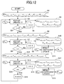
- Update of the gain vector necessary for high speed estimation of the optimized weight coefficients is performed according to a process shown in Fig.12, for example, in the adaptive controller 84 in the BFN.
- ⁇ K ( ⁇ ) ⁇ of the gain vector K indicates values of the register for representing relationship between the gain vector K and the corresponding register sequence.
- the adaptive controller 84 updates the gain vector estimated up to the time k -1 by using received signals r k,j received from the antenna elements. That is, update operation of the gain vector (S2) is performed by using signals received by the time k -1 which are stored in the gain vector (S1), all signals extracted from a plurality of signals and a signal r k,j received by the i th array antenna element. Any one of the dimension extension type high speed Kalman algorithm and the dimension extension type FTF algorithm can be used as the high speed algorithm used for the update operation for the gain vector.
- the first signal d k,1 (0) is extracted by using the gain vector (S6) on the basis of the estimation result in the SINR estimation part.
- " k " in d k,1 (0) indicates time, "1" indicates signal number and "(0)” indicates stage number of BFN.
- the values in the register of the gain vector (S6) corresponds to the first signal d k,1 (0) .
- the gain vector is updated by using a signal extracted by using the first signal d k,1 (0) .
- the weight coefficient can be calculated (S11) by using the updated gain vector (S10).
- the second signal d k,2 (0) can be generated, a signal can be extracted, and the weight coefficient can be updated.
- the gain vector is updated every time when the signal is extracted one by one like third signal, fourth signal, ... ,Kth signal.
- update operation of the weight coefficient estimation is performed (S7) ⁇ (S11) repeatedly on the basis of the gain vector so that the weight coefficient estimation (S11) of a first stage is completed.
- time counter k is incremented by +1 (S16) and the signal extraction process is performed repeatedly.
- d k,K is input into the register by lengthening the register of the gain vector by one.
- d k,k (0) is input into the register and the dimension of the gain vector is extended by one. Then, only a signal which is desired to be extracted is output from the register, and the element corresponding to the register is excluded from the gain vector and the dimension of the gain vector is reduced by one. That is, by performing the dimension extension process, the gain vector and the register of a plurality of signals after the second stage are generated.
- the weight coefficients for a plurality of signals after the second stage can be updated by using the gain vector.
- the signal extraction apparatus 400 can be configured as shown in Fig.13 which shows a third embodiment.
- the signal extraction apparatus 400 includes an input terminal 99 which receives signals from all elements of the array antenna, an SINR estimation part 141 which estimates SINR of each output signal, BFNs 100 - 108, a matrix switch circuit 142, and output terminals 109 - 111.
- the BFNs 100 - 102 correspond to a first stage signal extraction part 1
- the BFNs 103 - 105 correspond to signal extraction parts after the second stage (from second to mth stage)
- the BFNs 106 ⁇ 108 corresponds to the final stage (m+1) th stage.
- the signal extraction apparatus 400 extracts signals ⁇ 2 (0) - ⁇ K (0) by performing the same process as the signal extraction apparatus shown in Fig.8 (step 201).
- the extracted signals ⁇ 2 (0) - ⁇ K (0) are input into the BFN 103, that is, into the BFN-C(1) which is the first BFN in the second stage after the signals ⁇ 2 (0) - ⁇ K (0) are adjusted as necessary.
- signals ⁇ 1 (1) - ⁇ K (1) are extracted by using the signals obtained in the signal extraction part 1 of the first stage and the received signals received by a plurality of antennas.
- signals are extracted by performing the signal extraction process like in the second stage repeatedly by the predetermined signal extraction parts. Then, when the signal extraction process at the (m+1)th stage ends, the signal extraction part m+1 extracts signals ⁇ 1 (m) - ⁇ K (m) (step 202).
- a k th BFN in the second signal extraction part or a later signal extraction part cancels, from the received signals, signal components extracted by BFNs in a previous stage signal extraction part other than a k th BFN in the previous stage signal extraction part so as to extract a kth signal.
- the signals ⁇ 1 (m) - ⁇ K (m) are logically sorted in descending order of SINR on the basis of SINR estimation result in the SINR estimation part 141.
- the matrix switch circuit 142 performs switching such that the signals are output one by one in descending order of SINR. As a result, final signals d 1 - d K are output from the output terminals 109 ⁇ 111.
- BFN-C( ⁇ )103 ⁇ 108 The basic structure of BFN-C( ⁇ )103 ⁇ 108 is the same as the BFN(K) 100 ⁇ 102 in Fig.13.
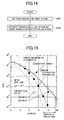
- Fig.15 shows a characteristic diagram (BER characteristic diagram) when the above-mentioned signal extraction apparatus 400 (first - third embodiments) is applied to a mobile wireless system which uses QPSK (Quadrature Phase Shift Keying).
- QPSK Quadrature Phase Shift Keying
- Fig.15 an array antenna of four element type is used in which the element interval is more than 10 ⁇ such that diversity gain can be obtained.
- ⁇ indicates wavelength of the wireless carrier.
- the signal extraction apparatus 400 shown in Fig.5 includes three signals and adopts the FTF algorithm as the dimension extension high speed algorithm.
- the transmission line is a Rayleigh fading channel, maximum Doppler frequency f D T which is normalized by the clock rate is 10 -6 .
- the characteristic when the signal extraction apparatus 400 is used is indicated by 2 ⁇ .
- a characteristic 1 ⁇ of a four element adaptive array, and characteristics 3 ⁇ and 4 ⁇ of maximum ratio synthesizing diversity of four branches and two branches respectively are shown for comparison with 2 ⁇ .
- the characteristic of the four element adaptive array indicates a characteristic of maximum ratio synthesizing diversity of two elements since two degrees of freedom are reduced by two interference waves.
- the CNR(dB) is about 13dB for the signal extraction apparatus 400 of the present invention.
- signals can be extracted accurately irrespective of the antenna element interval even when the number of interference waves is larger than the number of elements. Therefore, co-channel interference can be decreased on the basis of the extracted signals.
- the interference margin of the wireless communication system can be decreased, efficiency for using frequency can be improved and channel capacity can be increased.
- weight coefficient estimation and update can be performed easily and speedily by the high speed dimension extension algorithm, the amount of computation can be decreased, terminals and base stations can be provided economically and terminals having long continuous operation hour can be provided.
- the beam forming part cancels signal component which has been extracted from received signals received by a plurality of antennas. Since signal extraction is performed one by one according to the number of the beam forming parts, signals of high SINR can be extracted irrespective of the antenna element interval.
- the adaptive controller of the beam forming part controls estimation and update of the weight coefficient adaptively so as to cancel signal component which has been extracted from the received signals, the beam forming part can perform signal extraction with reliability.
Landscapes
- Engineering & Computer Science (AREA)
- Computer Networks & Wireless Communication (AREA)
- Signal Processing (AREA)
- Radio Transmission System (AREA)
- Mobile Radio Communication Systems (AREA)
- Variable-Direction Aerials And Aerial Arrays (AREA)
- Radar Systems Or Details Thereof (AREA)
Abstract
Description
a dimension extension type algorithm is used for estimation of the weight coefficients, one kind of gain vector is generated, and the gain vector is used for the estimation and update of the weight coefficients.




Claims (15)
- A signal extraction method in which signals are extracted by using K beam forming parts, wherein K is a natural number equal to or more than 2, and received signals from a plurality of antennas are applied to each beam forming part, said signal extraction method characterized by the steps of:said received signals being processed by each beam forming part successively;a first beam forming part extracting a first signal from said received signals; anda kth beam forming part canceling, from said received signals, signal components which are extracted by beam forming parts from said first beam forming part to a (k-1)th beam forming part so as to extract a kth signal, wherein 2≦k≦K.
- A signal extraction method in which signals are extracted by using signal extraction parts, characterized in that received signals from a plurality of antennas are applied to each signal extraction part, said signal extraction parts being connected, each signal extraction part including K beam forming parts, wherein K is a natural number equal to or more than 2, said signal extraction method including the steps of:said received signals being processed by each beam forming part successively in a first signal extraction part;a first beam forming part in said first signal extraction part extracting a first signal from said received signals;a kth beam forming part in said first signal extraction part canceling, from said received signals, signal components which are extracted by beam forming parts from said first beam forming part to a (k-1)th beam forming part so as to extract a kth signal, wherein 2≦k≦K; anda kth beam forming part in a second signal extraction part or a later signal extraction part canceling, from said received signals, signal components extracted by beam forming parts in a previous stage signal extraction part other than a kth beam forming part in said previous stage signal extraction part so as to extract a kth signal.
- The signal extraction method as claimed in claim 1, further comprising the steps of:estimating an SINR value of a signal on the basis of said received signals; andchanging order in which said beam forming parts perform signal extraction.
- The signal extraction method as claimed in claim 2, further comprising the steps of:estimating an SINR value of a signal on the basis of said received signals; andchanging order in which said beam forming parts perform signal extraction.
- A signal extraction apparatus which extracts signals from received signals from a plurality of antennas, said signal extraction apparatus characterized by:K beam forming parts, wherein K is a natural number equal to or more than 2, and said received signals are applied to each beam forming part;said received signals being processed by each beam forming part successively;a first beam forming part extracting a first signal from said received signals; anda kth beam forming part canceling, from said received signals, signal components which are extracted by beam forming parts from said first beam forming part to a (k-1)th beam forming part so as to extract a kth signal, wherein 2≦k≦K.
- A signal extraction apparatus which extracts signals from received signals from a plurality of antennas, said signal extraction apparatus characterized by:signal extraction parts which are connected, each signal extraction part receiving said received signals;each signal extraction part including K beam forming parts, wherein K is a natural number equal to or more than 2;each beam forming part processing said received signals successively in a first signal extraction part;a first beam forming part in said first signal extraction part extracting a first signal from said received signals;a kth beam forming part in said first signal extraction part canceling, from said received signals, signal components which are extracted by beam forming parts from said first beam forming part to a (k-1)th beam forming part so as to extract a kth signal, wherein 2≦k≦K; anda kth beam forming part in a second signal extraction part or a later signal extraction part canceling, from said received signals, signal components extracted by beam forming parts in a previous stage signal extraction part other than a kth beam forming part in said previous stage signal extraction part so as to extract a kth signal.
- The signal extraction apparatus as claimed in claim 5, further comprising:an SINR estimation part which estimates an SINR value of a signal on the basis of said received signals; and whereinorder in which said beam forming parts perform signal extraction is changed on the basis of said SINR value.
- The signal extraction apparatus as claimed in claim 6, further comprising:an SINR estimation part which estimates an SINR value of a signal on the basis of said received signals; and whereinorder in which said beam forming parts perform signal extraction is changed on the basis of said SINR value.
- The signal estimation apparatus as claimed in claim 7, comprising:K SINR estimation parts;each SINR estimation part comprising beam forming parts, subtracters, square circuits and a minimum state estimation part;a kth beam forming part in said beam forming parts receiving said received signals and signals extracted by beam forming parts up to (k-1) th beam forming part in which 0≦k-1≦K-1, and outputting an extraction signal other than signals extracted by beam forming parts up to (k-1)th beam forming part;said subtracter performing subtraction between a known signal and an said extraction signal so as to obtain a value, said known signal corresponding to a predetermined signal component other than signals extracted by beam forming parts up to said (k-1) th beam forming part;said value being input into said square circuit so that an error is calculated;said minimum state estimation part detecting a minimum value according to said error so that an SINR estimation result is output.
- The signal extraction apparatus as claimed in claim 5, said beam forming part comprising an adder, an error detection part, first multipliers to which said received signals are applied, second multipliers to which signals extracted by beam forming parts up to (k-1)th beam forming part are applied, and an adaptive controller;wherein said weight coefficients are assigned to said received signals and signals extracted by beam forming parts up to (k-1)th beam forming part in said first and second multipliers, said signals to which said weight coefficients are assigned are applied to said adder, and an output signal of said adder is applied to said error detection part.said adaptive controller receiving signals extracted by beam forming parts up to (k-1)th beam forming part and an error signal detected by said error detection part;said adaptive controller estimating weight coefficients of said first and second multipliers so as to cancel, from said received signals, signal components extracted by beam forming parts up to (k-1)th beam forming part and extract only a predetermined signal; and
- The signal extraction apparatus as claimed in claim 6, said beam forming part comprising an adder, an error detection part, first multipliers to which said received signals are applied, second multipliers to which signals extracted by beam forming parts up to (k-1)th beam forming part are applied, and an adaptive controller;wherein said weight coefficients are assigned to said received signals and signals extracted by beam forming parts up to (k-1)th beam forming part in said first and second multipliers, said signals to which said weight coefficients are assigned are applied to said adder, and an output signal of said adder is applied to said error detection part.said adaptive controller receiving signals extracted by beam forming parts up to (k-1)th beam forming part and an error signal detected by said error detection part;said adaptive controller estimating weight coefficients of said first and second multipliers so as to cancel, from said received signals, signal components extracted by beam forming parts up to (k-1) th beam forming part and extract only a predetermined signal; and
- The signal estimation apparatus as claimed in claim 5, said beam forming part comprising feedforward filters and feedback filters with tap delay line, an adaptive controller and an adder;each feedforward filter receiving a received signal from an antenna corresponding to said each feedforward filter, performing weighting and adding operation by using tap coefficient estimated by said adaptive controller adaptively, and said adder receiving outputs from said feedforward filters so as to extract a predetermined signal;said predetermined signal being applied to said feedback filters; andeach feedback filter performing weighting and adding operation by using tap coefficients estimated by said adaptive controller adaptively, and said adder receiving outputs from said feedback filters.
- The signal estimation apparatus as claimed in claim 6, said beam forming part comprising feedforward filters and feedback filters with tap delay line, an adaptive controller and an adder;each feedforward filter receiving a received signal from an antenna corresponding to said each feedforward filter, performing weighting and adding operation by using tap coefficient estimated by said adaptive controller adaptively, and said adder receiving outputs from said feedforward filters so as to extract a predetermined signal;said predetermined signal being applied to said feedback filters; andeach feedback filter performing weighting and adding operation by using tap coefficients estimated by said adaptive controller adaptively, and said adder receiving outputs from said feedback filters.
- The signal extraction apparatus as claimed in claim 12, said adaptive controller estimating said weight coefficients adaptively so as to canceling, from said received signals, signal components extracted by beam forming parts up to (k-1)th beam forming part; wherein
a dimension extension type algorithm is used for estimation of said weight coefficients, one kind of gain vector is generated, and said gain vector is used for said estimation and update of said weight coefficients. - The signal extraction apparatus as claimed in claim 13, said adaptive controller estimating said weight coefficients adaptively so as to canceling, from said received signals, signal components extracted by beam forming parts up to (k-1)th beam forming part; wherein
a dimension extension type algorithm is used for estimation of said weight coefficients, one kind of gain vector is generated, and said gain vector is used for said estimation and update of said weight coefficients.
Applications Claiming Priority (2)
| Application Number | Priority Date | Filing Date | Title |
|---|---|---|---|
| JP2000280709 | 2000-09-14 | ||
| JP2000280709A JP2002094318A (en) | 2000-09-14 | 2000-09-14 | Signal extraction method and apparatus in wireless communication system |
Publications (2)
| Publication Number | Publication Date |
|---|---|
| EP1189303A2 true EP1189303A2 (en) | 2002-03-20 |
| EP1189303A3 EP1189303A3 (en) | 2004-11-24 |
Family
ID=18765493
Family Applications (1)
| Application Number | Title | Priority Date | Filing Date |
|---|---|---|---|
| EP01307786A Withdrawn EP1189303A3 (en) | 2000-09-14 | 2001-09-12 | Beam forming method and apparatus in a wireless communication system |
Country Status (3)
| Country | Link |
|---|---|
| US (1) | US7016437B2 (en) |
| EP (1) | EP1189303A3 (en) |
| JP (1) | JP2002094318A (en) |
Cited By (24)
| Publication number | Priority date | Publication date | Assignee | Title |
|---|---|---|---|---|
| EP1318609A3 (en) * | 2001-11-13 | 2004-09-15 | NTT DoCoMo, Inc. | Decoding method and communication device |
| US9014066B1 (en) | 2013-11-26 | 2015-04-21 | Magnolia Broadband Inc. | System and method for transmit and receive antenna patterns calibration for time division duplex (TDD) systems |
| US9042276B1 (en) | 2013-12-05 | 2015-05-26 | Magnolia Broadband Inc. | Multiple co-located multi-user-MIMO access points |
| WO2015077029A1 (en) * | 2013-11-20 | 2015-05-28 | Magnolia Broadband Inc. | System and method for side lobe suppression using controlled signal cancellation |
| US9060362B2 (en) | 2013-09-12 | 2015-06-16 | Magnolia Broadband Inc. | Method and system for accessing an occupied Wi-Fi channel by a client using a nulling scheme |
| US9088898B2 (en) | 2013-09-12 | 2015-07-21 | Magnolia Broadband Inc. | System and method for cooperative scheduling for co-located access points |
| US9100154B1 (en) | 2014-03-19 | 2015-08-04 | Magnolia Broadband Inc. | Method and system for explicit AP-to-AP sounding in an 802.11 network |
| US9100968B2 (en) | 2013-05-09 | 2015-08-04 | Magnolia Broadband Inc. | Method and system for digital cancellation scheme with multi-beam |
| US9155110B2 (en) | 2013-03-27 | 2015-10-06 | Magnolia Broadband Inc. | System and method for co-located and co-channel Wi-Fi access points |
| US9172454B2 (en) | 2013-11-01 | 2015-10-27 | Magnolia Broadband Inc. | Method and system for calibrating a transceiver array |
| US9172446B2 (en) | 2014-03-19 | 2015-10-27 | Magnolia Broadband Inc. | Method and system for supporting sparse explicit sounding by implicit data |
| US9236998B2 (en) | 2013-11-19 | 2016-01-12 | Magnolia Broadband Inc. | Transmitter and receiver calibration for obtaining the channel reciprocity for time division duplex MIMO systems |
| US9271176B2 (en) | 2014-03-28 | 2016-02-23 | Magnolia Broadband Inc. | System and method for backhaul based sounding feedback |
| US9294177B2 (en) | 2013-11-26 | 2016-03-22 | Magnolia Broadband Inc. | System and method for transmit and receive antenna patterns calibration for time division duplex (TDD) systems |
| US9300378B2 (en) | 2013-02-08 | 2016-03-29 | Magnolia Broadband Inc. | Implementing multi user multiple input multiple output (MU MIMO) base station using single-user (SU) MIMO co-located base stations |
| US9313805B2 (en) | 2013-07-10 | 2016-04-12 | Magnolia Broadband Inc. | System and method for simultaneous co-channel access of neighboring access points |
| US9332519B2 (en) | 2013-11-20 | 2016-05-03 | Magnolia Broadband Inc. | System and method for selective registration in a multi-beam system |
| US9343808B2 (en) | 2013-02-08 | 2016-05-17 | Magnotod Llc | Multi-beam MIMO time division duplex base station using subset of radios |
| US9344168B2 (en) | 2012-05-29 | 2016-05-17 | Magnolia Broadband Inc. | Beamformer phase optimization for a multi-layer MIMO system augmented by radio distribution network |
| US9385793B2 (en) | 2013-02-13 | 2016-07-05 | Magnolia Broadband Inc. | Multi-beam co-channel Wi-Fi access point |
| US9425882B2 (en) | 2013-06-28 | 2016-08-23 | Magnolia Broadband Inc. | Wi-Fi radio distribution network stations and method of operating Wi-Fi RDN stations |
| US9497781B2 (en) | 2013-08-13 | 2016-11-15 | Magnolia Broadband Inc. | System and method for co-located and co-channel Wi-Fi access points |
| CN113314843A (en) * | 2021-05-11 | 2021-08-27 | 西安电子科技大学 | Side lobe suppression method suitable for conformal antenna array |
| FR3114463A1 (en) * | 2020-09-24 | 2022-03-25 | Thales | SYSTEM AND METHOD FOR SUPPRESSING UPWARD INTERFERING SIGNALS GENERATED WITHIN A MULTI-SPOTS SPACE COMMUNICATION SYSTEM |
Families Citing this family (9)
| Publication number | Priority date | Publication date | Assignee | Title |
|---|---|---|---|---|
| JP4507482B2 (en) * | 2002-05-15 | 2010-07-21 | 日本電気株式会社 | Adaptive antenna transmitter |
| KR100617843B1 (en) * | 2003-07-26 | 2006-08-28 | 삼성전자주식회사 | System and method for signal transmission / reception in mobile communication system using adaptive antenna array method |
| AU2003294780A1 (en) * | 2003-10-31 | 2005-06-08 | Telefonaktiebolaget Lm Ericsson (Publ) | Multiple access interference cancellation |
| US7532664B2 (en) * | 2004-08-02 | 2009-05-12 | Nokia Corporation | Method and apparatus to estimate signal to interference plus noise ratio (SINR) in a multiple antenna receiver |
| US7525926B2 (en) * | 2004-08-02 | 2009-04-28 | Atheros Communications, Inc. | Wireless communication using beam forming and diversity |
| JP2007006219A (en) * | 2005-06-24 | 2007-01-11 | Mitsubishi Electric Corp | Adaptive antenna device |
| EP2575274B1 (en) * | 2011-09-27 | 2013-10-09 | NTT DoCoMo, Inc. | Method and receiver for recovering a desired signal transmitted in the presence of one or more interference signals |
| US11978966B2 (en) * | 2020-01-14 | 2024-05-07 | Src, Inc. | Method for beamforming |
| CN113970730B (en) * | 2021-09-23 | 2025-03-14 | 武汉滨湖电子有限责任公司 | A sidelobe cancellation method for adaptive multipath interference suppression in clutter environments |
Family Cites Families (3)
| Publication number | Priority date | Publication date | Assignee | Title |
|---|---|---|---|---|
| US3763490A (en) * | 1971-12-10 | 1973-10-02 | Gen Electric | Adaptive beamformer with time constant control |
| US4349696A (en) * | 1979-02-05 | 1982-09-14 | Hitachi, Ltd. | AM Stereophonic demodulator circuit for amplitude/angle modulation system |
| JPH07123027A (en) * | 1993-10-26 | 1995-05-12 | Fujitsu Ltd | Digital subscriber line transmission equipment |
-
2000
- 2000-09-14 JP JP2000280709A patent/JP2002094318A/en not_active Withdrawn
-
2001
- 2001-09-12 EP EP01307786A patent/EP1189303A3/en not_active Withdrawn
- 2001-09-14 US US09/951,740 patent/US7016437B2/en not_active Expired - Fee Related
Cited By (27)
| Publication number | Priority date | Publication date | Assignee | Title |
|---|---|---|---|---|
| EP1318609A3 (en) * | 2001-11-13 | 2004-09-15 | NTT DoCoMo, Inc. | Decoding method and communication device |
| US9344168B2 (en) | 2012-05-29 | 2016-05-17 | Magnolia Broadband Inc. | Beamformer phase optimization for a multi-layer MIMO system augmented by radio distribution network |
| US9343808B2 (en) | 2013-02-08 | 2016-05-17 | Magnotod Llc | Multi-beam MIMO time division duplex base station using subset of radios |
| US9300378B2 (en) | 2013-02-08 | 2016-03-29 | Magnolia Broadband Inc. | Implementing multi user multiple input multiple output (MU MIMO) base station using single-user (SU) MIMO co-located base stations |
| US9385793B2 (en) | 2013-02-13 | 2016-07-05 | Magnolia Broadband Inc. | Multi-beam co-channel Wi-Fi access point |
| US9155110B2 (en) | 2013-03-27 | 2015-10-06 | Magnolia Broadband Inc. | System and method for co-located and co-channel Wi-Fi access points |
| US9100968B2 (en) | 2013-05-09 | 2015-08-04 | Magnolia Broadband Inc. | Method and system for digital cancellation scheme with multi-beam |
| US9425882B2 (en) | 2013-06-28 | 2016-08-23 | Magnolia Broadband Inc. | Wi-Fi radio distribution network stations and method of operating Wi-Fi RDN stations |
| US9313805B2 (en) | 2013-07-10 | 2016-04-12 | Magnolia Broadband Inc. | System and method for simultaneous co-channel access of neighboring access points |
| US9497781B2 (en) | 2013-08-13 | 2016-11-15 | Magnolia Broadband Inc. | System and method for co-located and co-channel Wi-Fi access points |
| US9088898B2 (en) | 2013-09-12 | 2015-07-21 | Magnolia Broadband Inc. | System and method for cooperative scheduling for co-located access points |
| US9060362B2 (en) | 2013-09-12 | 2015-06-16 | Magnolia Broadband Inc. | Method and system for accessing an occupied Wi-Fi channel by a client using a nulling scheme |
| US9172454B2 (en) | 2013-11-01 | 2015-10-27 | Magnolia Broadband Inc. | Method and system for calibrating a transceiver array |
| US9236998B2 (en) | 2013-11-19 | 2016-01-12 | Magnolia Broadband Inc. | Transmitter and receiver calibration for obtaining the channel reciprocity for time division duplex MIMO systems |
| WO2015077029A1 (en) * | 2013-11-20 | 2015-05-28 | Magnolia Broadband Inc. | System and method for side lobe suppression using controlled signal cancellation |
| US9332519B2 (en) | 2013-11-20 | 2016-05-03 | Magnolia Broadband Inc. | System and method for selective registration in a multi-beam system |
| US9294177B2 (en) | 2013-11-26 | 2016-03-22 | Magnolia Broadband Inc. | System and method for transmit and receive antenna patterns calibration for time division duplex (TDD) systems |
| US9014066B1 (en) | 2013-11-26 | 2015-04-21 | Magnolia Broadband Inc. | System and method for transmit and receive antenna patterns calibration for time division duplex (TDD) systems |
| US9042276B1 (en) | 2013-12-05 | 2015-05-26 | Magnolia Broadband Inc. | Multiple co-located multi-user-MIMO access points |
| US9100154B1 (en) | 2014-03-19 | 2015-08-04 | Magnolia Broadband Inc. | Method and system for explicit AP-to-AP sounding in an 802.11 network |
| US9172446B2 (en) | 2014-03-19 | 2015-10-27 | Magnolia Broadband Inc. | Method and system for supporting sparse explicit sounding by implicit data |
| US9271176B2 (en) | 2014-03-28 | 2016-02-23 | Magnolia Broadband Inc. | System and method for backhaul based sounding feedback |
| FR3114463A1 (en) * | 2020-09-24 | 2022-03-25 | Thales | SYSTEM AND METHOD FOR SUPPRESSING UPWARD INTERFERING SIGNALS GENERATED WITHIN A MULTI-SPOTS SPACE COMMUNICATION SYSTEM |
| EP3975434A1 (en) * | 2020-09-24 | 2022-03-30 | Thales | System and method for suppressing interfering uplink signals generated inside a spatial system for multi-spot communication |
| US11888576B2 (en) | 2020-09-24 | 2024-01-30 | Thales | System and method for suppressing uplink interference signals generated in a multi-spot space communication system |
| CN113314843A (en) * | 2021-05-11 | 2021-08-27 | 西安电子科技大学 | Side lobe suppression method suitable for conformal antenna array |
| CN113314843B (en) * | 2021-05-11 | 2022-06-10 | 西安电子科技大学 | Side lobe suppression method suitable for conformal antenna array |
Also Published As
| Publication number | Publication date |
|---|---|
| US20020044615A1 (en) | 2002-04-18 |
| US7016437B2 (en) | 2006-03-21 |
| JP2002094318A (en) | 2002-03-29 |
| EP1189303A3 (en) | 2004-11-24 |
Similar Documents
| Publication | Publication Date | Title |
|---|---|---|
| US7016437B2 (en) | Signal extraction method and apparatus in wireless communication system | |
| JP4847874B2 (en) | Multi-user adaptive array receiver and method | |
| US6128486A (en) | Reception method and base station receiver | |
| US6657590B2 (en) | Adaptive antenna reception apparatus using reception signals by arrays antennas | |
| US6069912A (en) | Diversity receiver and its control method | |
| KR100447841B1 (en) | Adaptive antenna reception apparatus with weight updated adaptively | |
| US7161976B2 (en) | Interference canceller | |
| EP1093241A1 (en) | Adaptive transmitter/receiver | |
| JP3591581B2 (en) | Adaptive antenna receiver | |
| WO2001058049A2 (en) | Linear signal separation using polarization diversity | |
| JP2005535171A (en) | Array receiver with subarray selection, method of using the same, and reception system incorporating the same | |
| CA2261841C (en) | Adaptive receiving device for antennas | |
| WO2006070478A1 (en) | Wireless communication system | |
| US7221698B2 (en) | Adaptive array antenna receiving apparatus | |
| US20030068993A1 (en) | Radio base station apparatus and radio communication method | |
| US7298774B2 (en) | Adaptive array device, adaptive array method and program | |
| EP1146665A1 (en) | Base station device and radio receiving method | |
| JP3808311B2 (en) | Reception method and receiver | |
| EP1102419A1 (en) | Receiving device and method of generating replica signal | |
| JPH08331025A (en) | Adaptive interference cancellation receiver | |
| JPH11205209A (en) | Receiver | |
| AU1861499A (en) | Radio communications receiver and method of receiving radio signals | |
| CRISAN et al. | Multiple-Input Adaptive Combiner-Equalizer for Wireless Communications | |
| Denno | Multibeam interference canceller based on order extended fast algorithms | |
| Shibagaki et al. | Path-diversity reception technique based on least square combining in digital mobile communications |
Legal Events
| Date | Code | Title | Description |
|---|---|---|---|
| PUAI | Public reference made under article 153(3) epc to a published international application that has entered the european phase |
Free format text: ORIGINAL CODE: 0009012 |
|
| 17P | Request for examination filed |
Effective date: 20010929 |
|
| AK | Designated contracting states |
Kind code of ref document: A2 Designated state(s): AT BE CH CY DE DK ES FI FR GB GR IE IT LI LU MC NL PT SE TR |
|
| AX | Request for extension of the european patent |
Free format text: AL;LT;LV;MK;RO;SI |
|
| PUAL | Search report despatched |
Free format text: ORIGINAL CODE: 0009013 |
|
| AK | Designated contracting states |
Kind code of ref document: A3 Designated state(s): AT BE CH CY DE DK ES FI FR GB GR IE IT LI LU MC NL PT SE TR |
|
| AX | Request for extension of the european patent |
Extension state: AL LT LV MK RO SI |
|
| RIC1 | Information provided on ipc code assigned before grant |
Ipc: 7H 01Q 3/26 B Ipc: 7H 04B 7/08 A |
|
| 17Q | First examination report despatched |
Effective date: 20050118 |
|
| AKX | Designation fees paid |
Designated state(s): DE GB IT |
|
| STAA | Information on the status of an ep patent application or granted ep patent |
Free format text: STATUS: THE APPLICATION IS DEEMED TO BE WITHDRAWN |
|
| 18D | Application deemed to be withdrawn |
Effective date: 20060301 |