EP1189258A2 - Vacuum arc evaporation apparatus - Google Patents
Vacuum arc evaporation apparatus Download PDFInfo
- Publication number
- EP1189258A2 EP1189258A2 EP01121279A EP01121279A EP1189258A2 EP 1189258 A2 EP1189258 A2 EP 1189258A2 EP 01121279 A EP01121279 A EP 01121279A EP 01121279 A EP01121279 A EP 01121279A EP 1189258 A2 EP1189258 A2 EP 1189258A2
- Authority
- EP
- European Patent Office
- Prior art keywords
- anode
- cathode
- vacuum arc
- arc evaporation
- magnetic
- Prior art date
- Legal status (The legal status is an assumption and is not a legal conclusion. Google has not performed a legal analysis and makes no representation as to the accuracy of the status listed.)
- Withdrawn
Links
- 238000001704 evaporation Methods 0.000 title claims abstract description 251
- 230000008020 evaporation Effects 0.000 title claims abstract description 174
- 230000005291 magnetic effect Effects 0.000 claims abstract description 348
- 238000010891 electric arc Methods 0.000 claims abstract description 78
- 230000002093 peripheral effect Effects 0.000 claims abstract description 13
- 239000011362 coarse particle Substances 0.000 claims description 28
- 239000010406 cathode material Substances 0.000 claims description 24
- OKTJSMMVPCPJKN-UHFFFAOYSA-N Carbon Chemical compound [C] OKTJSMMVPCPJKN-UHFFFAOYSA-N 0.000 claims description 23
- 229910052799 carbon Inorganic materials 0.000 claims description 22
- 239000000463 material Substances 0.000 claims description 20
- 239000000696 magnetic material Substances 0.000 claims description 18
- 238000001816 cooling Methods 0.000 claims description 15
- 230000007246 mechanism Effects 0.000 claims description 7
- 239000003507 refrigerant Substances 0.000 claims description 5
- 239000003302 ferromagnetic material Substances 0.000 abstract description 4
- 239000000758 substrate Substances 0.000 description 24
- 239000007789 gas Substances 0.000 description 20
- 230000032258 transport Effects 0.000 description 14
- 150000002500 ions Chemical class 0.000 description 13
- 230000000694 effects Effects 0.000 description 12
- 239000010408 film Substances 0.000 description 10
- 239000002245 particle Substances 0.000 description 8
- -1 containing carbon Chemical compound 0.000 description 7
- 230000004907 flux Effects 0.000 description 5
- 238000001069 Raman spectroscopy Methods 0.000 description 4
- 238000010276 construction Methods 0.000 description 4
- 238000000034 method Methods 0.000 description 4
- 229910000975 Carbon steel Inorganic materials 0.000 description 3
- RYGMFSIKBFXOCR-UHFFFAOYSA-N Copper Chemical compound [Cu] RYGMFSIKBFXOCR-UHFFFAOYSA-N 0.000 description 3
- 230000002411 adverse Effects 0.000 description 3
- 239000010962 carbon steel Substances 0.000 description 3
- 239000003575 carbonaceous material Substances 0.000 description 3
- 229910052802 copper Inorganic materials 0.000 description 3
- 239000010949 copper Substances 0.000 description 3
- 238000010586 diagram Methods 0.000 description 3
- 230000005294 ferromagnetic effect Effects 0.000 description 3
- 239000011810 insulating material Substances 0.000 description 3
- 239000010409 thin film Substances 0.000 description 3
- XEEYBQQBJWHFJM-UHFFFAOYSA-N Iron Chemical compound [Fe] XEEYBQQBJWHFJM-UHFFFAOYSA-N 0.000 description 2
- PXHVJJICTQNCMI-UHFFFAOYSA-N Nickel Chemical compound [Ni] PXHVJJICTQNCMI-UHFFFAOYSA-N 0.000 description 2
- 229910045601 alloy Inorganic materials 0.000 description 2
- 239000000956 alloy Substances 0.000 description 2
- 238000010420 art technique Methods 0.000 description 2
- 239000002826 coolant Substances 0.000 description 2
- 238000010292 electrical insulation Methods 0.000 description 2
- 230000006872 improvement Effects 0.000 description 2
- 239000011261 inert gas Substances 0.000 description 2
- 238000009413 insulation Methods 0.000 description 2
- 238000007733 ion plating Methods 0.000 description 2
- 229910052751 metal Inorganic materials 0.000 description 2
- 239000002184 metal Substances 0.000 description 2
- 229910001220 stainless steel Inorganic materials 0.000 description 2
- 239000010935 stainless steel Substances 0.000 description 2
- 229910000859 α-Fe Inorganic materials 0.000 description 2
- 229910018979 CoPt Inorganic materials 0.000 description 1
- 229910001030 Iron–nickel alloy Inorganic materials 0.000 description 1
- 229910010038 TiAl Inorganic materials 0.000 description 1
- RTAQQCXQSZGOHL-UHFFFAOYSA-N Titanium Chemical compound [Ti] RTAQQCXQSZGOHL-UHFFFAOYSA-N 0.000 description 1
- 239000010941 cobalt Substances 0.000 description 1
- 229910017052 cobalt Inorganic materials 0.000 description 1
- GUTLYIVDDKVIGB-UHFFFAOYSA-N cobalt atom Chemical compound [Co] GUTLYIVDDKVIGB-UHFFFAOYSA-N 0.000 description 1
- 230000006866 deterioration Effects 0.000 description 1
- 230000005684 electric field Effects 0.000 description 1
- 239000010419 fine particle Substances 0.000 description 1
- 239000011521 glass Substances 0.000 description 1
- 229910002804 graphite Inorganic materials 0.000 description 1
- 239000010439 graphite Substances 0.000 description 1
- 229910052742 iron Inorganic materials 0.000 description 1
- 229910001105 martensitic stainless steel Inorganic materials 0.000 description 1
- 229910052759 nickel Inorganic materials 0.000 description 1
- 230000000149 penetrating effect Effects 0.000 description 1
- 230000035699 permeability Effects 0.000 description 1
- 230000008569 process Effects 0.000 description 1
- 229910052705 radium Inorganic materials 0.000 description 1
- HCWPIIXVSYCSAN-UHFFFAOYSA-N radium atom Chemical compound [Ra] HCWPIIXVSYCSAN-UHFFFAOYSA-N 0.000 description 1
- 239000012495 reaction gas Substances 0.000 description 1
- 230000009467 reduction Effects 0.000 description 1
- 239000004065 semiconductor Substances 0.000 description 1
- 239000010936 titanium Substances 0.000 description 1
- 229910052719 titanium Inorganic materials 0.000 description 1
Images





Classifications
-
- H—ELECTRICITY
- H01—ELECTRIC ELEMENTS
- H01J—ELECTRIC DISCHARGE TUBES OR DISCHARGE LAMPS
- H01J37/00—Discharge tubes with provision for introducing objects or material to be exposed to the discharge, e.g. for the purpose of examination or processing thereof
- H01J37/32—Gas-filled discharge tubes
- H01J37/32009—Arrangements for generation of plasma specially adapted for examination or treatment of objects, e.g. plasma sources
- H01J37/32055—Arc discharge
-
- H—ELECTRICITY
- H01—ELECTRIC ELEMENTS
- H01J—ELECTRIC DISCHARGE TUBES OR DISCHARGE LAMPS
- H01J37/00—Discharge tubes with provision for introducing objects or material to be exposed to the discharge, e.g. for the purpose of examination or processing thereof
- H01J37/32—Gas-filled discharge tubes
- H01J37/32431—Constructional details of the reactor
- H01J37/3266—Magnetic control means
Definitions
- the present invention relates to a vacuum arc evaporation apparatus used for forming a thin film on a surface of a substrate, such as automobile part, machine part, tool, mold, lens, glass, or a semiconductor substrate. More specifically, the invention relates to a vacuum arc evaporation apparatus with a magnetic filter which generates a magnetic field, and curves and transports a stream of plasma generated by a vacuum arc evaporation source under the generated magnetic field, and outputs the plasma stream after removing coarse particles from the plasma, wherein the maintaining of arc discharge in the vacuum arc evaporation source is prevented from being difficult when an efficiency of transporting the plasma stream is increased by increasing an intensity of the magnetic field developed by the magnetic filter.
- the vacuum arc evaporation source evaporates a cathode by vacuum arc discharge to thereby generate the plasma containing a cathode material.
- This method is called a vacuum arc evaporation method or an arc ion plating method.
- This method has advantageous features of high film-forming rate and high adhesion property.
- the high film-forming rate is due to the fact that a large amount of cathode material is evaporated from the cathode by the utilization of the vacuum arc discharge.
- the high adhesion property is due to the fact that ions contained in the plasma draw toward the substrate and collided therewith under an electric field caused by the negative bias voltage.
- the cathode material evaporated from the cathode of the vacuum arc evaporation source contains fine particles preferable for the film-forming, and coarse particles (also called droplets or macro-particles) whose diameter is several ⁇ m to several tens ⁇ m. Adhesion of such coarse particles to the substrate causes deterioration of the smoothness and adhesion property of a surface of the resultant film.
- the vacuum arc evaporation apparatus 10a includes a vacuum arc evaporation source 20 as referred to above, and a magnetic filter 50.
- the magnetic filter 50 curves and transports a stream of plasma 38 generated by the vacuum arc evaporation source 20 under a magnetic field, and outputs the plasma stream after removing the coarse particles from the plasma.
- the vacuum arc evaporation source 20 includes a cathode 30 mounted on a cathode holder 24, and a cylindrical or annular anode 36 disposed in front of an evaporating face 32 of the cathode 30 (in an evaporating direction of the cathode material 34).
- the cathode 30 is caused to evaporate cathode materials by the vacuum arc discharge occurring between the cathode 30 and the anode 36, thereby generating plasma containing the cathode materials (making the cathode 30).
- the cathode 30 contains amaterial (e.g., metal of titanium or the like, alloy of TiAl, carbon (graphite) or the like), which is selected in accordance with a kind of film to be formed.
- the anode 36 is usually made of copper.
- the cathode holder 24 is made of a non-magnetic metal.
- the anode 36 is electrically grounded.
- Arc discharge voltage of several tens V to 100V or therearound is applied from an arc power source 44 to between the anode 36 and the cathode 30, with the cathode 30 being at the negative polarity.
- Reference numeral 40 is a trigger electrode and 42 is an insulating material.
- the cathode holder 24 is mounted on a support plate 28 through an insulating material 26.
- the support plate 28 covers one end of a transporting duct 52 forming the magnetic filter 50.
- a magnet (permanent magnet) 22 for confining an arc spot (cathode point of the arc discharge) within the evaporating face 32 of the cathode 30 by a magnetic field is provided on the rear side of the cathode holder 24.
- the magnetic filter 50 includes the curved transporting duct 52, a magnetic coil 54 , and a DC power source 56.
- the magnetic coil 54 generates a magnetic field curved along the transporting duct 52.
- the DC power source 56 excites the magnetic coil 54.
- the magnetic coil 54 may be a plurality of toroidal coils as illustrated, or a solenoid coil wound around the outer peripheral part of the transporting duct 52.
- Part of magnetic lines 58 of force generated by the magnetic coil 54 is roughly illustrated in Fig. 11.
- the magnetic lines 58 extend along the inner wall of the transporting duct 52 as shown. In a region including the cathode 30 and the anode 36, the magnetic lines 58 are distributed as illustrated in Fig. 12.
- An angle ⁇ of the curve of the transporting duct 52 is preferably selected such that a substrate 64 in a film-forming chamber 60 cannot be seen directly from the cathode 30 in the vacuum arc evaporation source 20.
- a specific example of ⁇ is about 90°.
- the members located close to the magnetic coil 54 e.g., the transporting duct 52, the support plate 28 and the film-forming chamber 60, are made of non-magnetic material so as not to disturb the magnetic lines 58 (magnetic field) developed by the magnetic coil 54.
- the vacuum arc evaporation apparatus 10a including the vacuum arc evaporation source 20 and the magnetic filter 50 is coupled to the film-forming chamber 60 in a state that the other end of the transporting duct 52 (opposite to the vacuum arc evaporation source 20) is directed to the substrate 64, whereby a film-forming apparatus is formed.
- the film-forming chamber 60 includes a holder 62 holding the substrate 64 on which a film is to be formed.
- the film-forming apparatus is called a vacuum arc evaporation apparatus or an arc ion plating apparatus.
- the transporting duct 52, together with the film-forming chamber 60, is vacuumed by a vacuuming apparatus.
- the plasma stream 38 generated by the vacuum arc evaporation source 20 is transported along the magnetic field within the magnetic filter 50, and output from the other end of the magnetic filter 50 and led to near the substrate 64 within the film-forming chamber 60.
- those particles not charged straightforwardly move while not being influenced by the magnetic field, and collide with the inner wall of the transporting duct 52. Accordingly, those coarse particles are not derived from the magnetic filter 50 and fail to reach the substrate 64.
- the radium (Raman radius) of a spiral motion of a coarse particle in the magnetic field extremely increases proportional to a mass of the coarse particle, even if it is the charged one.
- the intensity of magnetic field by the magnetic coil 54 is increased, a larger number of the magnetic lines 58 generated by the magnetic coil 54 pass through the space within the anode 36. As a result, the electrons 37 do not hit the anode 36 and are easy to pass through the anode 36.
- the cathode 30 is made of carbon or a material mainly containing carbon
- the maintaining of the arc discharge is more difficult when the field strength in the magnetic filter 50 is increased.
- the reason for this is that the arc discharge of the carbon or the material mainly containing carbon is originally difficult, and that the electrons 37 emitted from the cathode 30 hardly reach the anode 36 as described above and hence, the arc discharge more hardly occurs.
- the arc discharge may easily be maintained in a manner that gas, e.g., inert gas or reaction gas, is introduced into the transporting duct 52, thereby intentionally increasing a gas pressure in the vicinity of the cathode 30.
- gas e.g., inert gas or reaction gas
- this approach creates other problems anew.
- a large amount of gas ion caused by the arc discharge is contained in the plasma stream 38, and adversely affects the film-forming process.
- a large amount of gas ion enters the substrate 64, so that a film quality of a thin film formed on a surface of the substrate 64 is changed, an internal stress in the film increases, or the substrate 64 is heated unnecessarily.
- an object of the present invention is to provide a vacuum arc evaporation apparatus including a vacuum arc evaporation source and a magnetic filter in which arc discharge can be maintained within the vacuum arc evaporation source without the gas introduction even when an efficiency of transporting plasma stream is improved by increasing an intensity of magnetic field developed by the magnetic filter.
- a first vacuum arc evaporation apparatus comprising: a vacuum arc evaporation source including a cathode and an anode located in front of an evaporating face of the cathode, the vacuum arc evaporation source generating stream of plasma containing cathode materials by evaporating cathode materials from the cathode under a vacuum arc discharge between the cathode and the anode; a magnetic filter for curving and transporting the plasma stream generated by the vacuum arc evaporation source by a magnetic field to remove coarse particles from the plasma stream, and outputting the plasma stream in which coarse particles have been removed; and a magnetic member disposed in front of the evaporating face of the cathode and close to the anode in the vacuum arc evaporation source.
- a distribution of the magnetic lines of force (i.e., magnetic flux) developed by the magnetic filter in the region ranging from the cathode to the anode in the vacuum arc evaporation source is configured so as to be suitable for the maintaining of arc discharge between the cathode and the anode.
- the magnetic lines developed by the magnetic filter are attracted in part to the magnetic member. This phenomenon occurs also when the field strength of the magnetic filter is increased. Accordingly, the magnetic lines passing through the anode or its vicinity from the cathode of the vacuum arc evaporation source are increased in number.
- the arc discharge can be stabilized and maintained in the vacuum arc evaporation source without gas introduction. Accordingly, the transport efficiency improvement of the plasma stream in the magnetic filter and the arc discharge maintaining in the vacuum arc evaporation source can both be secured without the gas introduction.
- the film-forming apparatus having the thus constructed vacuum arc evaporation apparatus can form a film on a substrate at high rate in a manner that the plasma stream is transported at high transport efficiency, while removing coarse particles, and further can eliminate the adverse effect on the formed film by the gas introduction.
- Those advantageous effects may be achieved by very simple construction, viz., provision of the magnetic member. This fact also suppresses the apparatus size increase.
- the anode is located between the magnetic member and the evaporating face of the cathode.
- the magnetic member is not interposed between the evaporating face of the cathode and the anode. Accordingly, electrons that are emitted from the cathode and captured by the magnetic lines of force are easy to reach the anode. This is very convenient for the maintaining of the arc discharge.
- the anode of the vacuum arc evaporation source is configured such that when positioned in place, the anode surrounds the front part of the cathode, and the magnetic member is disposed on or near an outer peripheral part of the anode in a state that the magnetic member is located in front of the cathode while surrounding the front part of the cathode.
- the magnetic member is disposed so as to surround the front part of the cathode. Where the magnetic member is used as described above, the magnetic lines may be attracted to the anode or its vicinity. The effects comparable with those of the first vacuum arc evaporation apparatus are more remarkably manifested.
- the anode of the vacuum arc evaporation source may include a plurality of bar-like members, which are disposed along the evaporating face of the cathode while being located outside the evaporating face of the cathode.
- Electrons emitted from the cathode are easy to pass between the anode while not colliding with the anode, if the magnetic member is not used, when an intensity of magnetic field generated by the magnetic filter is increased as in the case where the anode surrounds the front part of the cathode when it is positioned in place.
- the magnetic member With provision of the magnetic member, the magnetic field generated by the magnetic filter is attracted to the anode or its vicinity. Accordingly, the number of magnetic lines of force going to the anode is increased, thereby enabling the arc discharge to be maintained in a strong magnetic field. Therefore, the effects of this vacuum arc evaporation apparatus are comparable with those of the first vacuum arc evaporation apparatus.
- a second vacuum arc evaporation apparatus comprising: a vacuum arc evaporation source including a cathode and an anode located in front of an evaporating face of the cathode, the vacuum arc evaporation source generating stream of plasma containing cathode materials by evaporating cathode materials from the cathode under a vacuum arc discharge between the cathode and the anode; and a magnetic filter for curving and transporting the plasma stream generated by the vacuum arc evaporation source by a magnetic field to remove coarse particles from the plasma stream, and outputting the plasma stream in which coarse particles have been removed, wherein the anode of the vacuum arc evaporation source is made of a magnetic material.
- the anode of the vacuum arc evaporation source is configured such that when positioned in place, the anode surrounds the front part of the cathode.
- the anode of the vacuum arc evaporation source includes a plurality of bar-like members, which are disposed along the evaporating face of the cathode while being located outside the evaporating face of the cathode.
- the anode per se attracts magnetic lines of force generated by the magnetic filter. Accordingly, the number of magnetic lines going to the anode is increased, enabling the arc discharge to be maintained in a strong magnetic field.
- the advantageous effects produced by this apparatus are comparable with those of the first vacuum arc evaporation apparatus. Further, reduction of the number of required parts and construction simplification are secured.
- a third vacuum arc evaporation apparatus comprising: a vacuum arc evaporation source including a cathode and an anode located in front of an evaporating face of the cathode, the vacuum arc evaporation source generating stream of plasma containing cathode materials by evaporating cathode materials from the cathode under a vacuum arc discharge between the cathode and the anode; and a magnetic filter for curving and transporting the plasma stream generated by the vacuum arc evaporation source by a magnetic field to remove coarse particles from the plasma stream, and outputting the plasma stream in which coarse particles have been removed, wherein the anode of the vacuum arc evaporation source includes at least one bar-like anode which is disposed in front of the evaporating face of the cathode while being extended along the evaporating face.
- the third vacuum arc evaporation apparatus even in a case where an intensity of magnetic field developed by the magnetic filter is increased and magnetic lines of force developed by the magnetic coil passes through the evaporating face in the direction perpendicular to the evaporating face, the electrons captured by the magnetic lines are easy to reach the anode and hence the arc discharge can be maintained since the anode is located crossing the magnetic lines. Accordingly, even in such a case of increasing the transport efficiency of the plasma stream by increasing the intensity of magnetic field generated by the magnetic filter, the arc discharge can be maintained in the vacuum arc evaporation source without the gas introduction.
- the third vacuum arc evaporation apparatus further may comprise: a magnetic filter disposed close to the at least one bar-like anode such that the bar-like anode is located between the magnetic member and the evaporating face of the cathode.
- a magnetic filter disposed close to the at least one bar-like anode such that the bar-like anode is located between the magnetic member and the evaporating face of the cathode.
- the bar-like anode is made of magnetic material.
- a fourth vacuum arc evaporation apparatus comprising: a vacuum arc evaporation source including a cathode and an anode located in front of an evaporating face of the cathode, the vacuum arc evaporation source generating stream of plasma containing cathode materials by evaporating cathode materials from the cathode under a vacuum arc discharge between the cathode and the anode; and a magnetic filter for curving and transporting the plasma stream generated by the vacuum arc evaporation source by a magnetic field to remove coarse particles from the plasma stream, and outputting the plasma stream in which coarse particles have been removed, wherein the anode of the vacuum arc evaporation source includes at least one bar-like anode which is disposed such that one end face of the bar-like anode is directed to the front of the evaporating face of the cathode.
- the fourth vacuum arc evaporation apparatus even in a case where an intensity of magnetic field developed by the magnetic filter is increased and magnetic lines of force developed by the magnetic coil passes through the evaporating face in the direction substantially perpendicular to the evaporating face, the electrons captured by the magnetic lines are easy to reach the anode and hence the arc discharge can be maintained since the anode is located along the magnetic lines. Accordingly, even in such a case of increasing the transport efficiency of the plasma stream by increasing the intensity of magnetic field generated by the magnetic filter, the arc discharge can be maintained in the vacuum arc evaporation source without introducing the gas into the transporting duct, as in other apparatuses.
- the anode is thus disposed, electrons collide with the anode, whereby the arc discharge is well maintained since the Raman radius of the electron is different from that of the ion in a magnetic field (the former is smaller than the latter) .
- a probability that the ions in the plasma are transported downstream while not colliding with the anode is high. Accordingly, the efficiency of transporting plasma stream is improved when comparing with the third vacuum arc evaporation apparatus.
- the fourth vacuum arc evaporation apparatus further may comprise: a magnetic filter disposed close to the at least one bar-like anode such that the bar-like anode is located between the magnetic member and the evaporating face of the cathode.
- the anode is made of magnetic material.
- a potential at the magnetic member may be equal to that at the anode.
- the magnetic member is mounted on the anode in the vacuum arc evaporation source.
- the anode serves also as a support of the magnetic member. Accordingly, the support of the magnetic member is easy.
- a potential of the magnetic member also may be a floating potential.
- the first to fourth vacuum arc evaporation apparatus further may comprise: a cooling mechanism for cooling the magnetic member by a refrigerant which is disposed in as sociation with the magnetic member, or a cooling mechanism for cooling the anode by a refrigerant which is disposed in association with the anode.
- the cathode may be made of carbon or a material mainly containing carbon.
- the vacuum arc evaporation apparatus can maintain the arc discharge in the strong magnetic field even if the cathode is made of a carbon material and no gas introduction is made. This feature will produce effects that are more advantageous.
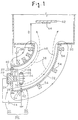
- Fig. 1 is a cross sectional view showing a film-forming apparatus having a vacuum arc evaporation device incorporated thereinto, which is constructed according to the invention.
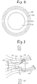
- Fig. 2 is an enlarged, front view showing a cathode, an anode and a magnetic member in the film-forming apparatus of Fig. 1.
- like reference numerals will be used for designating like or equivalent portions in the prior art film-forming apparatus shown in Fig. 11, and description will be given placing emphasis on differences from the prior art film-forming apparatus.
- a cylindrical or annular magnetic member 46 is mounted on an outer peripheral part of a cylindrical or annular anode 36 as stated above in a vacuum arc evaporation source 20.
- the magnetic member 46 is set at a potential equal to the anode 36 (it is grounded in the embodiment).
- the anode 36 is located in front of an evaporating face 32 of the cathode 30. Accordingly, the magnetic member 46 mounted on the outer peripheral part thereof is also located in front of the evaporating face 32. With the mounting of the magnetic member 46 on the outer peripheral part of the anode 36, the anode 36 is located between the magnetic member 46 and the evaporating face 32 of the cathode 30.
- the magnetic member 46 may be made of a ferromagnetic material, such as iron, nickel, cobalt, an alloy containing them, or ferrite. Specific examples of those materials that may be used for the magnetic member 46 are structural carbon steel (e.g., SS400 of JIS), ferrite stainless steel, martensitic stainless steel (both of them are magnetic stainless steel), NiFe, and CoPt.
- the magnetic member 46 thus disposed configures a distribution of the magnetic lines 58 of force developed by the magnetic filter 50 (exactly a magnetic coil 54 thereof) in the region ranging from the cathode 30 to the anode 36 in the vacuum arc evaporation source 20 so as to be suitable for the maintaining of arc discharge between the cathode 30 and the anode 36.
- the magnetic lines developed by the magnetic coil 54 of the magnetic filter 50 are attracted in part to the magnetic member 46, as shown in Fig. 3. Accordingly, the magnetic lines 58 that are directed to the anode 36 of the vacuum arc evaporation source 20 or its vicinity, more exactly the magnetic lines 58 passing through a region ranging from the cathode 30 to the anode 36 and its vicinity in the vacuum arc evaporation source 20, are increased in number. This phenomenon occurs also when the field strength of the magnetic filter 50 is increased.
- the magnetic lines 58 thus configured in distribution effectively contributes to the maintaining of the arc discharge in the vacuum arc evaporation source 20.
- An electron 37 reaching the anode 36 is illustrated in model form in Fig. 3. With this, the initial arc discharge and the maintaining of the subsequent arc discharge are easy in the vacuum arc evaporation source 20, whereby the arc discharge is stabilized. The same thing is true for the case where an intensity of the magnetic field by the magnetic filter 50 is increased.
- the transporting efficiency of a stream of plasma 38 is improved by increasing an intensity of magnetic field developed by the magnetic filter 50, the arc discharge can be stabilized and maintained in the vacuum arc evaporation source 20 without introducing discharge maintaining gas, e.g., inert gas, transporting duct. Accordingly, the transport efficiency improvement of the plasma stream 38 in the magnetic filter 50 and the arc discharge maintaining in the vacuum arc evaporation source 20 can both be secured without the gas introduction.
- discharge maintaining gas e.g., inert gas
- the film-forming apparatus having the thus constructed vacuum arc evaporation apparatus can form a film on a substrate 64 at high rate in a manner that the plasma stream 38 is transported at high transport efficiency, while removing coarse particles, and further can eliminate the adverse effect on the formed film by the gas introduction.
- Those advantageous effects may be achieved by very simple construction, viz., provision of the magnetic member 46. This fact also suppresses the apparatus size increase.
- the cathode 30 is made of carbon or a material mainly containing carbon
- the maintaining of the arc discharge is very difficult for the prior art technique, as described above.
- the invention can maintain the arc discharge in the strong magnetic field even if the cathode 30 is made of a carbon material and no gas introduction is made. This feature will produce effects that are more advantageous.
- the potential of the magnetic member 46 may be equal to that of the anode 36, a floating potential, or a medium potential between the potentials of the anode 36 and the cathode 30. The reason for this is that what is important for the magnetic member 46 is not its potential, but its function to attract the magnetic lines 58 and direct them to the anode 36. The same thing is true for other embodiments.
- a simple way to put the magnetic member 46 and the anode 36 at the equal potential is to mount the magnetic member 46 on the anode 36 as in the Fig. 1 case. Another way is to place those at different positions and to electrically connect them to each other. Where the magnetic member 46 and the anode 36 are set at the equal potential, there is no need of taking no electrical insulation measure for them. In this respect, the insulation design is easy.
- Fig. 5 shows an example structure where the potential of the magnetic member 46 is set at the floating potential.
- the magnetic member 46 is disposed close to and around the outer peripheral part of the anode 36.
- an insulating material may be interposed between the magnetic member 46 and the anode 36.
- the magnetic member 46 is preferably located outside the anode 36 (as viewed in the radial direction of the anode 36) or downward of the anode 36 (as viewed in the traveling direction of cathode materials 34).
- the magnetic member 46 is preferably disposed so that the anode 36 is located between it and the evaporating face 32 of the cathode 30. If so done, the magnetic member 46 is not interposed between the evaporating face 32 of the cathode 30 and the anode 36. Accordingly, electrons 37 (Fig. 3) that are emitted from the cathode 30 and captured by the magnetic lines 58 of force are easy to reach the anode 36.
- the potential at the magnetic member 46 is the floating potential or the medium potential, it is especially preferable to dispose the magnetic member 46 as mentioned above.
- the magnetic member 46 may be considered as a part of the anode when viewed from an electrical standpoint. Accordingly, it is not essential to dispose the magnetic member 46 as mentioned above.
- annular arc spot confining plate 48 made of magnetic material sometimes is provided on the outer periphery of the cathode 30 as in the instance shown in Fig. 4.
- the arc spot confining plate 48 is flush with the evaporating face 32 of the cathode 30, while surrounding the evaporating face 32. Since the arc spot confining plate 48 is made of magnetic material, it shapes a magnetic flux derived from a magnet 22 and confines a movement of an arc spot within the evaporating face 32 of the cathode 30.
- the arc spot confining plate 48 with such a function and the magnetic member 46 may be combined in use. The same thing is true for other embodiments to be given later.
- the arc spot confining plate 48 and the magnetic member 46 are quite different from each other in their locations and functions, as described above. Accordingly, in a case where the arc spot confining plate 48 is provided and the magnetic member 46 is not provided, it is impossible for the arc spot confining plate 48 to produce the operation and advantageous effect as those of the magnetic member 46.
- the position at which the arc spot confining plate 48 is located is not the position at which the magnetic member 46 is located, viz., in front of the evaporating face 32 of the cathode 30 and near the anode 36. Accordingly, the arc spot confining plate 48 cannot have such a function that the number of magnetic lines of force going to the anode 36 is increased to maintain the arc discharge in a strong magnetic field.
- a distance L1 between the evaporating face 32 of the cathode 30 and the anode 36, and a distance L2 between the evaporating face 32 and the magnetic member 46 is too small, a spread of the arc discharge is small. If those distances are too large, it is difficult to maintain the arc discharge. To avoid this, those distances are selected to preferably be within 30mm to 120mm, more preferably 50mm to 80mm.
- the magnetic member 46 is provided separately from the anode 36.
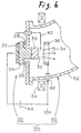
- the anode 36 in the vacuum arc evaporation source 20 is made of magnetic material (ferromagnetic material as already described, and the same thing is correspondingly applied to the other embodiments), and functions also as the magnetic member.
- the anode 36 per se attracts the magnetic lines 58 of force generated by the magnetic coil 54. Accordingly, the number of magnetic lines of force going to the anode 36 is increased, so that the arc discharge may be maintained in a strong magnetic field. Also, in the case where the efficiency of transporting the plasma stream 38 is increased by increasing the field strength of the magnetic filter 50, the arc discharge can be maintained without introducing the gas into a transporting duct 52.
- the magnetic member 46 is provided separately from the anode 36, materials suitable for those members may be selected independently; a material suitable for the magnetic member 46 is selected and a material suitable for the anode 36 is selected.
- a material suitable for the magnetic member 46 is selected and a material suitable for the anode 36 is selected.
- copper being high in electrical and thermal conductivity is used for the anode 36
- structural carbon steel being cheap and high in magnetic permeability is used for the magnetic member 46.
- the anode 36 is made of a ferromagnetic material to additionally have the function of the magnetic member, the number of required component parts is reduced and the construction is simplified. The same thing is true for the remaining embodiments.
- the magnetic member 46 is heated by charged particles penetrating thereinto, radiant heat radiated from the cathode surface and the like to have an increased temperature.
- a cooling mechanism for cooling the magnetic member by a refrigerant e.g., a coolant.
- a refrigerant e.g., a coolant
- the anode 36 is made of a magnetic material to additionally have the function of the magnetic member, as in the Fig. 6 case, it is preferable to apply the cooling mechanism as last stated to the anode 36. By so doing, there is no chance that the anode 36 is excessively heated to be deformed, damaged or the like. The same thing is true for the other embodiments.
- the vacuum arc evaporation source 20 may be provided with a plurality of cathodes 30.
- an anode 36 and a magnetic member 46 as constructed above, may be used commonly for those cathodes 30.
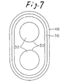
- Fig. 7 illustrates a case where two cathodes 30 are used.
- the combination o the anode 36 and the magnetic member 46 may be oval in flat surface shape as illustrated or elliptic. The same thing is true for the case where the anode 36 is made of a magnetic material to additionally have the function of the magnetic member.
- the anode 36 of the vacuum arc evaporation source 20 is configured such that when positioned in place, it surrounds the front part of the cathode 30.
- the magnetic member 46 is disposed on or near the outer peripheral part of the anode 36 in a state that it is located in front of the cathode 30 while surrounding the front part of the same.
- the anode 36 is made of a magnetic material, and serves also as the magnetic member .
- the anode 36 or magnetic member 46 so shaped as to surround the front part of the cathode 30 may be a tubular member whose cross section is circular, oval, elliptic, or square, or an annular member (involving a plate with a hole formed therein).
- the reason why the anode 36 is so shaped is that the anode 36 hardly intercepts (hinders) the cathode materials 34 evaporating from the evaporating face 32 of the cathode 30 and the plasma stream 38 derived therefrom.
- the anode 36 is thus shaped, if the intensity of the magnetic field of the magnetic filter 50 is increased, the magnetic lines 58 of force generated by the magnetic coil 54 pass through the space inside the anode 36, as shown in Fig. 12. With this, electrons 37 emitted from the cathode 30 do not hit the anode 36 but easily pass through the same. Accordingly, the advantageous effects resulting from the provision of the magnetic member 46 or of the case where the anode 36 is made of the magnetic material and serves also as the magnetic member are more manifestly produced.
- FIGs. 8A and 8B Another structure of the anode 36 and its arrangement in the vacuum arc evaporation source 20 is illustrated in Figs. 8A and 8B. As shown, a plurality of bars (two bars in the illustrated instance) are disposed along (e.g., parallel to) the evaporating face 32, while being located outside the evaporating face 32 of the cathode 30. Also, in this instance, as in the instance where the anode 36 surrounds the front part of the cathode 30, if the field strength developed by the magnetic filter 50 is increased, electrons emitted from the cathode 30 are easy to pass through the anode 36 while not hitting the anode 36.
- the magnetic members 46 are disposed such that the anodes 36 are located between the magnetic members 46 and the evaporating face 32 of the cathode 30 and close to the anodes 36.
- the anodes 36 may be made of a magnetic (ferromagnetic) material so as to additionally have the function of the magnetic member, instead of provision of the magnetic members 46.
- the magnetic members 46 or the anodes 36 made of a magnetic material draws, by itself, the magnetic lines 58 of force developed by the magnetic coil 54 of themagnetic filter 50 to the anodes 36 or their vicinity.
- the number of magnetic lines 58 going to the anodes 36 is increased, and this enables the arc discharge in the strong magnetic field to be maintained.
- the arc discharge may be maintained in the vacuum arc evaporation source 20 without introducing the gas into the transporting duct 52.
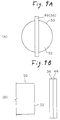
- FIG. 9A and 9B Yet another structure of the anode 36 and its arrangement is illustrated in Fig. 9A and 9B.
- one or more number of bar-like anodes 36 may be disposed in front of the evaporating face 32 of the cathode 30 while being extended along (e.g., parallel to) the evaporating face 32.
- the magnetic member 46 may be provided or the anode 36 may be made of a magnetic (ferromagnetic) material, as in the Figs. 8A and 8B case.
- the magnetic member 46 In the case using the magnetic member 46, it is located in front of the evaporating face 32 of the cathode 30 and close to each anode 36. Specifically, it is sufficient to dispose the magnetic member 46 such that the anode 36 is located between the magnetic member 46 and the evaporating face 32 of the cathode 30, as in the Figs. 9A and 9B case.
- the increased number of magnetic lines 58 of force pass through and near the anode 36, and electrons 37 are easy to reach the anode 36. Accordingly, it is easy to maintain the arc discharge in the strong magnetic field.
- FIG. 10A and 10B A further anode structure and its arrangement are shown in Figs. 10A and 10B.
- At least one bar-like anode 36 (one anode in the illustrated instance) is arranged such that one end face 35 of the bar-like anode is directed to the front of the evaporating face 32 of the cathode 30.
- the magnetic member 46 it is not essential that the magnetic member 46 is provided or the anode 36 is made of a magnetic material.
- the length of the anode 36 may be increased more than the Figs. 10A and 10B anode, whenever occasion calls.
- the Raman radius of the electron 37 emitted from the evaporating face 32 is small in the magnetic field. Accordingly, the electrons 37 collide with the anode 36, so that the arc discharge is well maintained.
- ions in the plasma stream 38 are heavy, and their Raman radius is much larger than that of the electrons 37 (the radius is 1cm or larger although it depends on the intensity of the magnetic field). Accordingly, the ions do not hit the anode 36, and hence, a probability that the ions are transported downstream is high. For this reason, the transport efficiency of the plasma stream 38 is higher than in the Figs. 9A and 9B case.
- the magnetic member 46 may be provided or the anode 36 may be made of a magnetic (ferromagnetic) material as in the Figs. 9A and 9B case. In the case using the magnetic member 46, it is located in front of the evaporating face 32 of the cathode 30 and close to each anode 36. Specifically, it is sufficient to dispose the magnetic member 46 such that the anode 36 is located between the magnetic member and the evaporating face 32 of the cathode 30, as in the Figs. 10A and 10B case.
- the increased number of magnetic lines 58 of force pass through and near the anode 36, and electrons 37 are easy to reach the anode 36. Accordingly, it is easy to maintain the arc discharge in a strong magnetic field.
- the matters on the setting of the potential of the magnetic member 46, whether or not the magnetic member 46 is coupled to the anode 36, and whether or not the cooling mechanism is coupled to the magnetic member 46 and the anode 36 may be considered as in the previous embodiments. Further, the advantageous effects are remarkably manifested when the cathode 30 is made of carbon or a material mainly containing it, as in the previous embodiments.
- a magnetic field may be formed which extends and curves along the transporting duct 52 by using a plurality of permanent magnets in place of the magnetic coil 54.
- the DC power source 56 is not required.
- the transporting duct 52 of the magnetic filter 50 may electrically be grounded or a bias voltage may be applied to the transporting duct 52.
- a film-forming test was conducted by using a film-forming apparatus having a vacuum arc evaporation apparatus 10c in which a magnetic member 46 is firmly mounted on the outer peripheral part of the anode 36 as shown in Fig. 1.
- the test conditions were as given hereunder, and the test results are shown in Table 1.
- SS400 of JIS is a kind of structural carbon steel. Currents flowing through the four coils of the magnetic coil 54 were equal to one another. A film-forming rate in the table was ratio with that in a case using a vacuum arc evaporation apparatus 10b not using the magnetic filter as shown in Fig. 13. A distance D used for comparison was a distance ranging from the evaporating face 32 of the cathode 30 to the substrate 64 as shown in Fig. 13, when the magnetic filter is not used. When the magnetic filter is used, it was a distance ranging from the exit of the magnetic filter 50 to the substrate 64 as shown in Fig. 1 and other figures. The distance D was 350mm in both cases, and in other examples and comparison.
- a film-forming test was conducted by using a film-forming apparatus including a vacuum arc evaporation apparatus 10c in which a magnetic member 46 is disposed close to and around the outer peripheral part of the anode 36 as shown in Fig. 5.
- the magnetic member 46 was made of SS400 of JIS, and cylindrical in shape, and its size was 85 in diameter x 5mm long x 2mm thick. It was electrically insulated from the anode 36, and hence, its potential was floating potential. The remaining conditions were the same as those in the example 1.
- a film-forming test was conducted by using a film-forming apparatus including a vacuum arc evaporation apparatus 10c in which the anode 36 is made of magnetic material and serves also as the magnetic member as shown in Fig. 6.
- the anode 36 was made of SS400 of JIS, and its shape was annular and its size was 85mm in diameter x 5mm long x 2mm thick.
- the anode 36 was of the water-cooled type. The other conditions than those were the same as those in the example 1.
- the test results are show in Table 4. Magnetic coil current(A) Arc discharge Maintaining Film-forming rate 10 possible 1/12 20 ditto 1/7 50 ditto 1/5 100 ditto 1/4 150 ditto 1/3
- the test results were substantially the same as in the example 1. Specifically, even when an intensity of magnetic field generated by the magnetic filter 50 is increased by increasing the current of the magnetic coil 54 from 10A to 150A, the arc discharge could be maintained for every current value of the magnetic coil. When the coil current was 150A, a film-forming rate was very fast, 1/3 as large as that in the case not using the magnetic filter 50.
Landscapes
- Physics & Mathematics (AREA)
- Engineering & Computer Science (AREA)
- Plasma & Fusion (AREA)
- Chemical & Material Sciences (AREA)
- Analytical Chemistry (AREA)
- Physical Vapour Deposition (AREA)
- Plasma Technology (AREA)
Abstract
Description
- The present invention relates to a vacuum arc evaporation apparatus used for forming a thin film on a surface of a substrate, such as automobile part, machine part, tool, mold, lens, glass, or a semiconductor substrate. More specifically, the invention relates to a vacuum arc evaporation apparatus with a magnetic filter which generates a magnetic field, and curves and transports a stream of plasma generated by a vacuum arc evaporation source under the generated magnetic field, and outputs the plasma stream after removing coarse particles from the plasma, wherein the maintaining of arc discharge in the vacuum arc evaporation source is prevented from being difficult when an efficiency of transporting the plasma stream is increased by increasing an intensity of the magnetic field developed by the magnetic filter.
- There is a method for forming a thin film on a surface of a substrate by drawing ions (which mean positive ions in this specification) contained in a plasma generated by a vacuum arc evaporation source toward the substrate under negative bias voltage or the like. The vacuum arc evaporation source evaporates a cathode by vacuum arc discharge to thereby generate the plasma containing a cathode material. This method is called a vacuum arc evaporation method or an arc ion plating method. This method has advantageous features of high film-forming rate and high adhesion property.
- The high film-forming rate is due to the fact that a large amount of cathode material is evaporated from the cathode by the utilization of the vacuum arc discharge. The high adhesion property is due to the fact that ions contained in the plasma draw toward the substrate and collided therewith under an electric field caused by the negative bias voltage.
- The cathode material evaporated from the cathode of the vacuum arc evaporation source contains fine particles preferable for the film-forming, and coarse particles (also called droplets or macro-particles) whose diameter is several µm to several tens µm. Adhesion of such coarse particles to the substrate causes deterioration of the smoothness and adhesion property of a surface of the resultant film.
- To cope with this, there is proposed a vacuum
arc evaporation apparatus 10a as shown in Fig. 11. The vacuumarc evaporation apparatus 10a includes a vacuumarc evaporation source 20 as referred to above, and amagnetic filter 50. Themagnetic filter 50 curves and transports a stream ofplasma 38 generated by the vacuumarc evaporation source 20 under a magnetic field, and outputs the plasma stream after removing the coarse particles from the plasma. - In the apparatus, the vacuum
arc evaporation source 20 includes acathode 30 mounted on acathode holder 24, and a cylindrical orannular anode 36 disposed in front of an evaporatingface 32 of the cathode 30 (in an evaporating direction of the cathode material 34). Thecathode 30 is caused to evaporate cathode materials by the vacuum arc discharge occurring between thecathode 30 and theanode 36, thereby generating plasma containing the cathode materials (making the cathode 30). - The
cathode 30 contains amaterial (e.g., metal of titanium or the like, alloy of TiAl, carbon (graphite) or the like), which is selected in accordance with a kind of film to be formed. Theanode 36 is usually made of copper. Thecathode holder 24 is made of a non-magnetic metal. - In this apparatus, the
anode 36 is electrically grounded. Arc discharge voltage of several tens V to 100V or therearound is applied from anarc power source 44 to between theanode 36 and thecathode 30, with thecathode 30 being at the negative polarity.Reference numeral 40 is a trigger electrode and 42 is an insulating material. - The
cathode holder 24 is mounted on asupport plate 28 through aninsulating material 26. Thesupport plate 28 covers one end of a transportingduct 52 forming themagnetic filter 50. A magnet (permanent magnet) 22 for confining an arc spot (cathode point of the arc discharge) within the evaporatingface 32 of thecathode 30 by a magnetic field is provided on the rear side of thecathode holder 24. - In this apparatus, the
magnetic filter 50 includes thecurved transporting duct 52, amagnetic coil 54 , and aDC power source 56. Themagnetic coil 54 generates a magnetic field curved along the transportingduct 52. TheDC power source 56 excites themagnetic coil 54. Themagnetic coil 54 may be a plurality of toroidal coils as illustrated, or a solenoid coil wound around the outer peripheral part of the transportingduct 52. Part ofmagnetic lines 58 of force generated by themagnetic coil 54 is roughly illustrated in Fig. 11. Themagnetic lines 58 extend along the inner wall of the transportingduct 52 as shown. In a region including thecathode 30 and theanode 36, themagnetic lines 58 are distributed as illustrated in Fig. 12. - An angle α of the curve of the transporting
duct 52 is preferably selected such that asubstrate 64 in a film-formingchamber 60 cannot be seen directly from thecathode 30 in the vacuumarc evaporation source 20. A specific example of α is about 90°. - The members located close to the
magnetic coil 54, e.g., the transportingduct 52, thesupport plate 28 and the film-formingchamber 60, are made of non-magnetic material so as not to disturb the magnetic lines 58 (magnetic field) developed by themagnetic coil 54. - The vacuum
arc evaporation apparatus 10a including the vacuumarc evaporation source 20 and themagnetic filter 50 is coupled to the film-formingchamber 60 in a state that the other end of the transporting duct 52 (opposite to the vacuum arc evaporation source 20) is directed to thesubstrate 64, whereby a film-forming apparatus is formed. The film-formingchamber 60 includes aholder 62 holding thesubstrate 64 on which a film is to be formed. The film-forming apparatus is called a vacuum arc evaporation apparatus or an arc ion plating apparatus. The transportingduct 52, together with the film-formingchamber 60, is vacuumed by a vacuuming apparatus. - The
plasma stream 38 generated by the vacuumarc evaporation source 20 is transported along the magnetic field within themagnetic filter 50, and output from the other end of themagnetic filter 50 and led to near thesubstrate 64 within the film-formingchamber 60. Of the coarse particles contained in theplasma stream 38, those particles not charged straightforwardly move while not being influenced by the magnetic field, and collide with the inner wall of the transportingduct 52. Accordingly, those coarse particles are not derived from themagnetic filter 50 and fail to reach thesubstrate 64. The radium (Raman radius) of a spiral motion of a coarse particle in the magnetic field extremely increases proportional to a mass of the coarse particle, even if it is the charged one. Accordingly, those particles hit the inner wall of the transportingduct 52 and fins (not shown) projected from the inner wall, anddisappear (adhere thereto) . As a result, theplasma stream 38 little containing the coarse particles are output from themagnetic filter 50, and led to near thesubstrate 64. Accordingly, there is no chance that the coarse particles adhere to thesubstrate 64. - At this time, when a potential at the
substrate 64 is lower than that of theplasma stream 38, for example, by applying a negative bias voltage to thesubstrate 64, the ions contained in theplasma stream 38 are drawn to thesubstrate 64 by the potential difference, so that the ions hit the latter. - In the vacuum
arc evaporation apparatus 10a, if an intensity of magnetic field (flux density) generated by themagnetic coil 54 of themagnetic filter 50 is increased, an efficiency of transporting theplasma stream 38 by themagnetic filter 50 is increased. Accordingly, the amount ofplasma stream 38 output from themagnetic filter 50 is increased and hence a film-forming rate at which a film is formed on thesubstrate 64 is increased. - When the field strength is increased, a magnetic field also increases in the vicinity of the
cathode 30 and theanode 36 in the vacuumarc evaporation source 20.Electrons 37 emitted from thecathode 30 by the arc discharge, as shown in Fig. 12, are firmly captured bymagnetic lines 58 generated by themagnetic coil 54, so that those electrons pass through a space within theanode 36 and are hard to reach theanode 36. As the intensity of magnetic field by themagnetic coil 54 is increased, a larger number of themagnetic lines 58 generated by themagnetic coil 54 pass through the space within theanode 36. As a result, theelectrons 37 do not hit theanode 36 and are easy to pass through theanode 36. When theelectrons 37 emitted from thecathode 30 are hard to reach theanode 36, it is difficult to maintain the arc discharge between thecathode 30 and theanode 36. In other words, an initial discharge is hard to occur between thecathode 30 and theanode 36. Further, it is difficult to maintain the subsequent discharge. - Thus, in the prior art vacuum
arc evaporation apparatus 10a, when attempt is made to increase an efficiency of transporting theplasma stream 38 by increasing an intensity of magnetic field by themagnetic filter 50, it is difficult to maintain the arc discharge in the vacuumarc evaporation source 20. Accordingly, it is difficult to secure both the transport efficiency of theplasma stream 38 and the maintaining of the arc discharge in the vacuumarc evaporation source 20. - Particularly, when the
cathode 30 is made of carbon or a material mainly containing carbon, the maintaining of the arc discharge is more difficult when the field strength in themagnetic filter 50 is increased. The reason for this is that the arc discharge of the carbon or the material mainly containing carbon is originally difficult, and that theelectrons 37 emitted from thecathode 30 hardly reach theanode 36 as described above and hence, the arc discharge more hardly occurs. - When the
cathode 30 is made of carbon or the material mainly containing carbon, which is difficult in maintaining the arc discharge, or even when it is made of another material, the arc discharge may easily be maintained in a manner that gas, e.g., inert gas or reaction gas, is introduced into the transportingduct 52, thereby intentionally increasing a gas pressure in the vicinity of thecathode 30. However, this approach creates other problems anew. A large amount of gas ion caused by the arc discharge is contained in theplasma stream 38, and adversely affects the film-forming process. A large amount of gas ion enters thesubstrate 64, so that a film quality of a thin film formed on a surface of thesubstrate 64 is changed, an internal stress in the film increases, or thesubstrate 64 is heated unnecessarily. - Accordingly, an object of the present invention is to provide a vacuum arc evaporation apparatus including a vacuum arc evaporation source and a magnetic filter in which arc discharge can be maintained within the vacuum arc evaporation source without the gas introduction even when an efficiency of transporting plasma stream is improved by increasing an intensity of magnetic field developed by the magnetic filter.
- The above-mentioned object can be achieved by a first vacuum arc evaporation apparatus according to the present invention, comprising: a vacuum arc evaporation source including a cathode and an anode located in front of an evaporating face of the cathode, the vacuum arc evaporation source generating stream of plasma containing cathode materials by evaporating cathode materials from the cathode under a vacuum arc discharge between the cathode and the anode; a magnetic filter for curving and transporting the plasma stream generated by the vacuum arc evaporation source by a magnetic field to remove coarse particles from the plasma stream, and outputting the plasma stream in which coarse particles have been removed; and a magnetic member disposed in front of the evaporating face of the cathode and close to the anode in the vacuum arc evaporation source.
- In the first vacuum arc evaporation apparatus, with provision of the magnetic member, a distribution of the magnetic lines of force (i.e., magnetic flux) developed by the magnetic filter in the region ranging from the cathode to the anode in the vacuum arc evaporation source is configured so as to be suitable for the maintaining of arc discharge between the cathode and the anode. Specifically, with the provision of the magnetic member near the anode, the magnetic lines developed by the magnetic filter are attracted in part to the magnetic member. This phenomenon occurs also when the field strength of the magnetic filter is increased. Accordingly, the magnetic lines passing through the anode or its vicinity from the cathode of the vacuum arc evaporation source are increased in number. As the result of the increase of the flux density, of electrons that are emitted from the cathode by the arc discharge, those electrons that are captured by the magnetic lines of force passing through the anode and its vicinity and reach the anode, are increased in number. With this, the initial arc discharge and the maintaining of the subsequent arc discharge are easy in the vacuum arc evaporation source, whereby the arc discharge is stabilized.
- Also, in a case where an efficiency of transporting a stream of plasma is improved by increasing an intensity of magnetic field developed by the magnetic filter, the arc discharge can be stabilized and maintained in the vacuum arc evaporation source without gas introduction. Accordingly, the transport efficiency improvement of the plasma stream in the magnetic filter and the arc discharge maintaining in the vacuum arc evaporation source can both be secured without the gas introduction.
- Thus, the film-forming apparatus having the thus constructed vacuum arc evaporation apparatus can form a film on a substrate at high rate in a manner that the plasma stream is transported at high transport efficiency, while removing coarse particles, and further can eliminate the adverse effect on the formed film by the gas introduction. Those advantageous effects may be achieved by very simple construction, viz., provision of the magnetic member. This fact also suppresses the apparatus size increase.
- In the first vacuum arc evaporation apparatus, it is preferable that the anode is located between the magnetic member and the evaporating face of the cathode.
- In the first vacuum arc evaporation apparatus, the magnetic member is not interposed between the evaporating face of the cathode and the anode. Accordingly, electrons that are emitted from the cathode and captured by the magnetic lines of force are easy to reach the anode. This is very convenient for the maintaining of the arc discharge.
- Further, in the first vacuum arc evaporation apparatus, it is also preferable that the anode of the vacuum arc evaporation source is configured such that when positioned in place, the anode surrounds the front part of the cathode, and the magnetic member is disposed on or near an outer peripheral part of the anode in a state that the magnetic member is located in front of the cathode while surrounding the front part of the cathode.
- Where the anode is not provided with the magnetic member, most of the magnetic lines generated by the magnetic filter pass through the space within the anode. With this, electrons emitted from the cathode are easy to pass through the anode while not colliding with the anode. In the vacuum arc evaporation apparatus according to the present invention, the magnetic member is disposed so as to surround the front part of the cathode. Where the magnetic member is used as described above, the magnetic lines may be attracted to the anode or its vicinity. The effects comparable with those of the first vacuum arc evaporation apparatus are more remarkably manifested.
- In the vacuum arc evaporation apparatus, the anode of the vacuum arc evaporation source may include a plurality of bar-like members, which are disposed along the evaporating face of the cathode while being located outside the evaporating face of the cathode.
- Electrons emitted from the cathode are easy to pass between the anode while not colliding with the anode, if the magnetic member is not used, when an intensity of magnetic field generated by the magnetic filter is increased as in the case where the anode surrounds the front part of the cathode when it is positioned in place. In the vacuum arc evaporation apparatus according to the present invention, with provision of the magnetic member, the magnetic field generated by the magnetic filter is attracted to the anode or its vicinity. Accordingly, the number of magnetic lines of force going to the anode is increased, thereby enabling the arc discharge to be maintained in a strong magnetic field. Therefore, the effects of this vacuum arc evaporation apparatus are comparable with those of the first vacuum arc evaporation apparatus.
- The above-mentioned object can be also achieved by a second vacuum arc evaporation apparatus according to the present invention, comprising: a vacuum arc evaporation source including a cathode and an anode located in front of an evaporating face of the cathode, the vacuum arc evaporation source generating stream of plasma containing cathode materials by evaporating cathode materials from the cathode under a vacuum arc discharge between the cathode and the anode; and a magnetic filter for curving and transporting the plasma stream generated by the vacuum arc evaporation source by a magnetic field to remove coarse particles from the plasma stream, and outputting the plasma stream in which coarse particles have been removed, wherein the anode of the vacuum arc evaporation source is made of a magnetic material.
- In the second vacuum arc evaporation apparatus, it is preferable that the anode of the vacuum arc evaporation source is configured such that when positioned in place, the anode surrounds the front part of the cathode.
- Further, in the second vacuum arc evaporation, it is also preferable that the anode of the vacuum arc evaporation source includes a plurality of bar-like members, which are disposed along the evaporating face of the cathode while being located outside the evaporating face of the cathode.
- In the second vacuum arc evaporation apparatus, the anode per se attracts magnetic lines of force generated by the magnetic filter. Accordingly, the number of magnetic lines going to the anode is increased, enabling the arc discharge to be maintained in a strong magnetic field. The advantageous effects produced by this apparatus are comparable with those of the first vacuum arc evaporation apparatus. Further, reduction of the number of required parts and construction simplification are secured.
- Further, the above-mentioned object ca be achieved by a third vacuum arc evaporation apparatus according to the present invention, comprising: a vacuum arc evaporation source including a cathode and an anode located in front of an evaporating face of the cathode, the vacuum arc evaporation source generating stream of plasma containing cathode materials by evaporating cathode materials from the cathode under a vacuum arc discharge between the cathode and the anode; and a magnetic filter for curving and transporting the plasma stream generated by the vacuum arc evaporation source by a magnetic field to remove coarse particles from the plasma stream, and outputting the plasma stream in which coarse particles have been removed, wherein the anode of the vacuum arc evaporation source includes at least one bar-like anode which is disposed in front of the evaporating face of the cathode while being extended along the evaporating face.
- In the third vacuum arc evaporation apparatus, even in a case where an intensity of magnetic field developed by the magnetic filter is increased and magnetic lines of force developed by the magnetic coil passes through the evaporating face in the direction perpendicular to the evaporating face, the electrons captured by the magnetic lines are easy to reach the anode and hence the arc discharge can be maintained since the anode is located crossing the magnetic lines. Accordingly, even in such a case of increasing the transport efficiency of the plasma stream by increasing the intensity of magnetic field generated by the magnetic filter, the arc discharge can be maintained in the vacuum arc evaporation source without the gas introduction.
- The third vacuum arc evaporation apparatus, further may comprise: a magnetic filter disposed close to the at least one bar-like anode such that the bar-like anode is located between the magnetic member and the evaporating face of the cathode. Or, in the third vacuum arc evaporation apparatus, it is preferable that the bar-like anode is made of magnetic material.
- In the vacuum arc evaporation apparatus, an increased number of magnetic lines pass through the anodes or their vicinity, so that electrons are easy to reach the anodes. Accordingly, the arc discharge in a strong magnetic field is easy.
- The above-mentionedobject can be also achieved by a fourth vacuum arc evaporation apparatus according to the present invention, comprising: a vacuum arc evaporation source including a cathode and an anode located in front of an evaporating face of the cathode, the vacuum arc evaporation source generating stream of plasma containing cathode materials by evaporating cathode materials from the cathode under a vacuum arc discharge between the cathode and the anode; and a magnetic filter for curving and transporting the plasma stream generated by the vacuum arc evaporation source by a magnetic field to remove coarse particles from the plasma stream, and outputting the plasma stream in which coarse particles have been removed, wherein the anode of the vacuum arc evaporation source includes at least one bar-like anode which is disposed such that one end face of the bar-like anode is directed to the front of the evaporating face of the cathode.
- In the fourth vacuum arc evaporation apparatus, even in a case where an intensity of magnetic field developed by the magnetic filter is increased and magnetic lines of force developed by the magnetic coil passes through the evaporating face in the direction substantially perpendicular to the evaporating face, the electrons captured by the magnetic lines are easy to reach the anode and hence the arc discharge can be maintained since the anode is located along the magnetic lines. Accordingly, even in such a case of increasing the transport efficiency of the plasma stream by increasing the intensity of magnetic field generated by the magnetic filter, the arc discharge can be maintained in the vacuum arc evaporation source without introducing the gas into the transporting duct, as in other apparatuses.
- Where the anode is thus disposed, electrons collide with the anode, whereby the arc discharge is well maintained since the Raman radius of the electron is different from that of the ion in a magnetic field (the former is smaller than the latter) . A probability that the ions in the plasma are transported downstream while not colliding with the anode is high. Accordingly, the efficiency of transporting plasma stream is improved when comparing with the third vacuum arc evaporation apparatus.
- The fourth vacuum arc evaporation apparatus, further may comprise: a magnetic filter disposed close to the at least one bar-like anode such that the bar-like anode is located between the magnetic member and the evaporating face of the cathode. Or, in the fourth vacuum arc evaporation apparatus, the anode is made of magnetic material.
- In the vacuum arc evaporation apparatus, an increased number of magnetic lines pass through the anodes or their vicinity, so that electrons are easy to reach the anodes. Accordingly, the arc discharge in a strong magnetic field is easy.
- In the first to fourth vacuum arc evaporation apparatus, a potential at the magnetic member may be equal to that at the anode.
- In the vacuum arc evaporation apparatus, there is no need of taking no electrical insulation measure for them. In this respect, the insulation design is easy.
- Preferably, in the vacuum arc evaporation apparatus, the magnetic member is mounted on the anode in the vacuum arc evaporation source.
- In the vacuum arc evaporation apparatus, the anode serves also as a support of the magnetic member. Accordingly, the support of the magnetic member is easy.
- In the first to fourth vacuum arc evaporation apparatus, a potential of the magnetic member also may be a floating potential.
- In the vacuum arc evaporation apparatus, charged particles are hard to approach to the magnetic member. Accordingly, less heat generated by the collision of the charged particles on the magnetic member is generated, and hence the cooling of the magnetic member is easy.
- The first to fourth vacuum arc evaporation apparatus, further may comprise: a cooling mechanism for cooling the magnetic member by a refrigerant which is disposed in as sociation with the magnetic member, or a cooling mechanism for cooling the anode by a refrigerant which is disposed in association with the anode.
- In the vacuum arc evaporation apparatus, there is no chance that the magnetic member is excessively heated and as a result, it is deformed, damaged or the like, or there is no chance that the anode is excessively heated and as a result, it is deformed, damaged or the like.
- In the first to fourth vacuum arc evaporation apparatus, the cathode may be made of carbon or a material mainly containing carbon.
- In a case where the cathode is made of carbon or a material mainly containing carbon, the maintaining of the arc discharge is very difficult for the prior art technique. On the other hand, the vacuum arc evaporation apparatus according to the present invention can maintain the arc discharge in the strong magnetic field even if the cathode is made of a carbon material and no gas introduction is made. This feature will produce effects that are more advantageous.
-
- Fig. 1 is a cross sectional view showing a film-forming apparatus with a vacuum arc evaporation apparatus incorporated thereinto;
- Fig. 2 is an enlarged, front view showing a portion including a cathode, an anode and a magnetic member;
- Fig. 3 is a diagram showing a distribution of magnetic lines of force in a region including the cathode and the anode and its vicinity in the vacuum arc evaporation apparatus;
- Fig. 4 is a cross sectional view showing a key portion of another vacuum arc evaporation apparatus;
- Fig. 5 is a diagram showing another arrangement of the magnetic member;
- Fig. 6 is a cross sectional view showing a key portion of yet another vacuum arc evaporation apparatus;
- Fig. 7 is an enlarged, front view showing a portion including cathodes, an anode and a magnetic member in a vacuum arc evaporation apparatus which uses two cathodes;
- Fig. 8A is a front view showing another arrangement of anodes and a magnetic member in the vacuum arc evaporation apparatus;
- Fig. 8B is a side view showing the same as Fig. 8A;
- Fig. 9A is a front view showing yet another arrangement of anodes and a magnetic member in the vacuum arc evaporation apparatus;
- Fig. 9B is a side view showing the same as Fig. 9A;
- Fig. 10A is a front view showing an additional arrangement of anodes and a magnetic member in the vacuum arc evaporation apparatus;
- Fig. 10B is a side view showing the same as Fig. 10A;
- Fig. 11 is a cross sectional view showing a film-forming apparatus having a prior art vacuum arc evaporation apparatus;
- Fig. 12 is a diagram showing a distribution of magnetic lines of force in a region including the cathode and the anode and its vicinity in the Fig. 11 vacuum arc evaporation apparatus; and
- Fig. 13 is a cross sectional view showing a film-forming apparatus having a prior art vacuum arc evaporation apparatus not using a magnetic filter.
-
- Fig. 1 is a cross sectional view showing a film-forming apparatus having a vacuum arc evaporation device incorporated thereinto, which is constructed according to the invention. Fig. 2 is an enlarged, front view showing a cathode, an anode and a magnetic member in the film-forming apparatus of Fig. 1. In the figures, like reference numerals will be used for designating like or equivalent portions in the prior art film-forming apparatus shown in Fig. 11, and description will be given placing emphasis on differences from the prior art film-forming apparatus.
- In the vacuum arc evaporation apparatus designated by
reference numeral 10c, a cylindrical or annularmagnetic member 46 is mounted on an outer peripheral part of a cylindrical orannular anode 36 as stated above in a vacuumarc evaporation source 20. Themagnetic member 46 is set at a potential equal to the anode 36 (it is grounded in the embodiment). - As stated above, the
anode 36 is located in front of an evaporatingface 32 of thecathode 30. Accordingly, themagnetic member 46 mounted on the outer peripheral part thereof is also located in front of the evaporatingface 32. With the mounting of themagnetic member 46 on the outer peripheral part of theanode 36, theanode 36 is located between themagnetic member 46 and the evaporatingface 32 of thecathode 30. - The
magnetic member 46 may be made of a ferromagnetic material, such as iron, nickel, cobalt, an alloy containing them, or ferrite. Specific examples of those materials that may be used for themagnetic member 46 are structural carbon steel (e.g., SS400 of JIS), ferrite stainless steel, martensitic stainless steel (both of them are magnetic stainless steel), NiFe, and CoPt. - The
magnetic member 46 thus disposed configures a distribution of themagnetic lines 58 of force developed by the magnetic filter 50 (exactly amagnetic coil 54 thereof) in the region ranging from thecathode 30 to theanode 36 in the vacuumarc evaporation source 20 so as to be suitable for the maintaining of arc discharge between thecathode 30 and theanode 36. - Specifically, with the mounting of the
magnetic member 46 on the outer peripheral part of theanode 36, the magnetic lines developed by themagnetic coil 54 of themagnetic filter 50 are attracted in part to themagnetic member 46, as shown in Fig. 3. Accordingly, themagnetic lines 58 that are directed to theanode 36 of the vacuumarc evaporation source 20 or its vicinity, more exactly themagnetic lines 58 passing through a region ranging from thecathode 30 to theanode 36 and its vicinity in the vacuumarc evaporation source 20, are increased in number. This phenomenon occurs also when the field strength of themagnetic filter 50 is increased. - The
magnetic lines 58 thus configured in distribution effectively contributes to the maintaining of the arc discharge in the vacuumarc evaporation source 20. As the result of the increase of the flux density, of electrons that are emitted from thecathode 30 by the arc discharge, those electrons that are captured by themagnetic lines 58 of force passing through theanode 36 and its vicinity, and reach theanode 36, are increased in number. Anelectron 37 reaching theanode 36 is illustrated in model form in Fig. 3. With this, the initial arc discharge and the maintaining of the subsequent arc discharge are easy in the vacuumarc evaporation source 20, whereby the arc discharge is stabilized. The same thing is true for the case where an intensity of the magnetic field by themagnetic filter 50 is increased. - Also in a case where the transporting efficiency of a stream of
plasma 38 is improved by increasing an intensity of magnetic field developed by themagnetic filter 50, the arc discharge can be stabilized and maintained in the vacuumarc evaporation source 20 without introducing discharge maintaining gas, e.g., inert gas, transporting duct. Accordingly, the transport efficiency improvement of theplasma stream 38 in themagnetic filter 50 and the arc discharge maintaining in the vacuumarc evaporation source 20 can both be secured without the gas introduction. - Thus, the film-forming apparatus having the thus constructed vacuum arc evaporation apparatus can form a film on a
substrate 64 at high rate in a manner that theplasma stream 38 is transported at high transport efficiency, while removing coarse particles, and further can eliminate the adverse effect on the formed film by the gas introduction. Those advantageous effects may be achieved by very simple construction, viz., provision of themagnetic member 46. This fact also suppresses the apparatus size increase. - In a case where the
cathode 30 is made of carbon or a material mainly containing carbon, the maintaining of the arc discharge is very difficult for the prior art technique, as described above. On the other hand, the invention can maintain the arc discharge in the strong magnetic field even if thecathode 30 is made of a carbon material and no gas introduction is made. This feature will produce effects that are more advantageous. - The potential of the
magnetic member 46 may be equal to that of theanode 36, a floating potential, or a medium potential between the potentials of theanode 36 and thecathode 30. The reason for this is that what is important for themagnetic member 46 is not its potential, but its function to attract themagnetic lines 58 and direct them to theanode 36. The same thing is true for other embodiments. - A simple way to put the
magnetic member 46 and theanode 36 at the equal potential is to mount themagnetic member 46 on theanode 36 as in the Fig. 1 case. Another way is to place those at different positions and to electrically connect them to each other. Where themagnetic member 46 and theanode 36 are set at the equal potential, there is no need of taking no electrical insulation measure for them. In this respect, the insulation design is easy. - Fig. 5 shows an example structure where the potential of the
magnetic member 46 is set at the floating potential. In the structure, as shown, themagnetic member 46 is disposed close to and around the outer peripheral part of theanode 36. In this case, an insulating material may be interposed between themagnetic member 46 and theanode 36. When themagnetic member 46 is set at a floating potential, charged particles, e.g., ions, are hard to approach to themagnetic member 46. Accordingly, less heat generated by the collision of the charged particles on themagnetic member 46 is generated, and hence the cooling of themagnetic member 46 is easy. - The
magnetic member 46, as described above, is preferably located outside the anode 36 (as viewed in the radial direction of the anode 36) or downward of the anode 36 (as viewed in the traveling direction of cathode materials 34). In other words, themagnetic member 46 is preferably disposed so that theanode 36 is located between it and the evaporatingface 32 of thecathode 30. If so done, themagnetic member 46 is not interposed between the evaporatingface 32 of thecathode 30 and theanode 36. Accordingly, electrons 37 (Fig. 3) that are emitted from thecathode 30 and captured by themagnetic lines 58 of force are easy to reach theanode 36. In a case where the potential at themagnetic member 46 is the floating potential or the medium potential, it is especially preferable to dispose themagnetic member 46 as mentioned above. In the case where the magnetic member 4 6 and theanode 36 are at the equal potential, themagnetic member 46 may be considered as a part of the anode when viewed from an electrical standpoint. Accordingly, it is not essential to dispose themagnetic member 46 as mentioned above. - By convention, an annular arc
spot confining plate 48 made of magnetic material sometimes is provided on the outer periphery of thecathode 30 as in the instance shown in Fig. 4. The arcspot confining plate 48 is flush with the evaporatingface 32 of thecathode 30, while surrounding the evaporatingface 32. Since the arcspot confining plate 48 is made of magnetic material, it shapes a magnetic flux derived from amagnet 22 and confines a movement of an arc spot within the evaporatingface 32 of thecathode 30. - The arc
spot confining plate 48 with such a function and themagnetic member 46 may be combined in use. The same thing is true for other embodiments to be given later. The arcspot confining plate 48 and themagnetic member 46 are quite different from each other in their locations and functions, as described above. Accordingly, in a case where the arcspot confining plate 48 is provided and themagnetic member 46 is not provided, it is impossible for the arcspot confining plate 48 to produce the operation and advantageous effect as those of themagnetic member 46. The position at which the arcspot confining plate 48 is located is not the position at which themagnetic member 46 is located, viz., in front of the evaporatingface 32 of thecathode 30 and near theanode 36. Accordingly, the arcspot confining plate 48 cannot have such a function that the number of magnetic lines of force going to theanode 36 is increased to maintain the arc discharge in a strong magnetic field. - If a distance L1 between the evaporating
face 32 of thecathode 30 and theanode 36, and a distance L2 between the evaporatingface 32 and the magnetic member 46 (see Fig. 5) is too small, a spread of the arc discharge is small. If those distances are too large, it is difficult to maintain the arc discharge. To avoid this, those distances are selected to preferably be within 30mm to 120mm, more preferably 50mm to 80mm. - Another or second embodiment of the present invention will be described. In the first embodiment described above, the
magnetic member 46 is provided separately from theanode 36. In the second embodiment, however, as shown in Fig. 6, theanode 36 in the vacuumarc evaporation source 20 is made of magnetic material (ferromagnetic material as already described, and the same thing is correspondingly applied to the other embodiments), and functions also as the magnetic member. - By so constructed, the
anode 36 per se attracts themagnetic lines 58 of force generated by themagnetic coil 54. Accordingly, the number of magnetic lines of force going to theanode 36 is increased, so that the arc discharge may be maintained in a strong magnetic field. Also, in the case where the efficiency of transporting theplasma stream 38 is increased by increasing the field strength of themagnetic filter 50, the arc discharge can be maintained without introducing the gas into a transportingduct 52. - Where the
magnetic member 46 is provided separately from theanode 36, materials suitable for those members may be selected independently; a material suitable for themagnetic member 46 is selected and a material suitable for theanode 36 is selected. In a specific example, copper being high in electrical and thermal conductivity is used for theanode 36, and structural carbon steel being cheap and high in magnetic permeability is used for themagnetic member 46. Where theanode 36 is made of a ferromagnetic material to additionally have the function of the magnetic member, the number of required component parts is reduced and the construction is simplified. The same thing is true for the remaining embodiments. - The
magnetic member 46 is heated by charged particles penetrating thereinto, radiant heat radiated from the cathode surface and the like to have an increased temperature. To cope with this, it is preferable to use a cooling mechanism for cooling the magnetic member by a refrigerant, e.g., a coolant. By so doing, there is no chance that themagnetic member 46 is excessively heated and as a result, it is deformed, damaged or the like. A specific means to cope with this is to lay a cooling pipe through which a coolant flows on and along the peripheral surface of themagnetic member 46. The same thing is correspondingly applied to the remaining embodiments. - In a case where the
anode 36 is made of a magnetic material to additionally have the function of the magnetic member, as in the Fig. 6 case, it is preferable to apply the cooling mechanism as last stated to theanode 36. By so doing, there is no chance that theanode 36 is excessively heated to be deformed, damaged or the like. The same thing is true for the other embodiments. - The vacuum
arc evaporation source 20 may be provided with a plurality ofcathodes 30. In this case, ananode 36 and amagnetic member 46, as constructed above, may be used commonly for thosecathodes 30. Fig. 7 illustrates a case where twocathodes 30 are used. The combination o theanode 36 and themagnetic member 46 may be oval in flat surface shape as illustrated or elliptic. The same thing is true for the case where theanode 36 is made of a magnetic material to additionally have the function of the magnetic member. - In either embodiment, the
anode 36 of the vacuumarc evaporation source 20 is configured such that when positioned in place, it surrounds the front part of thecathode 30. Themagnetic member 46 is disposed on or near the outer peripheral part of theanode 36 in a state that it is located in front of thecathode 30 while surrounding the front part of the same. In an alternative, theanode 36 is made of a magnetic material, and serves also as the magnetic member . Theanode 36 ormagnetic member 46 so shaped as to surround the front part of thecathode 30 may be a tubular member whose cross section is circular, oval, elliptic, or square, or an annular member (involving a plate with a hole formed therein). - The reason why the
anode 36 is so shaped is that theanode 36 hardly intercepts (hinders) thecathode materials 34 evaporating from the evaporatingface 32 of thecathode 30 and theplasma stream 38 derived therefrom. Where theanode 36 is thus shaped, if the intensity of the magnetic field of themagnetic filter 50 is increased, themagnetic lines 58 of force generated by themagnetic coil 54 pass through the space inside theanode 36, as shown in Fig. 12. With this,electrons 37 emitted from thecathode 30 do not hit theanode 36 but easily pass through the same. Accordingly, the advantageous effects resulting from the provision of themagnetic member 46 or of the case where theanode 36 is made of the magnetic material and serves also as the magnetic member are more manifestly produced. - Another structure of the
anode 36 and its arrangement in the vacuumarc evaporation source 20 is illustrated in Figs. 8A and 8B. As shown, a plurality of bars (two bars in the illustrated instance) are disposed along (e.g., parallel to) the evaporatingface 32, while being located outside the evaporatingface 32 of thecathode 30. Also, in this instance, as in the instance where theanode 36 surrounds the front part of thecathode 30, if the field strength developed by themagnetic filter 50 is increased, electrons emitted from thecathode 30 are easy to pass through theanode 36 while not hitting theanode 36. - Also, in this case, it is sufficient to provide the
magnetic members 46 at positions which are located in front of the evaporatingface 32 of thecathode 30 and near theanodes 36. Specifically, as in the Figs. 8A and 8B instance, themagnetic members 46 are disposed such that theanodes 36 are located between themagnetic members 46 and the evaporatingface 32 of thecathode 30 and close to theanodes 36. In an alternative, theanodes 36 may be made of a magnetic (ferromagnetic) material so as to additionally have the function of the magnetic member, instead of provision of themagnetic members 46. - Also in this case, the
magnetic members 46 or theanodes 36 made of a magnetic material draws, by itself, themagnetic lines 58 of force developed by themagnetic coil 54 ofthemagnetic filter 50 to theanodes 36 or their vicinity. As a result, the number ofmagnetic lines 58 going to theanodes 36 is increased, and this enables the arc discharge in the strong magnetic field to be maintained. Accordingly, also when the intensity of the magnetic field generated by themagnetic filter 50 is increased to increase the transport efficiency of theplasma stream 38 as in the above instance, the arc discharge may be maintained in the vacuumarc evaporation source 20 without introducing the gas into the transportingduct 52. - Yet another structure of the
anode 36 and its arrangement is illustrated in Fig. 9A and 9B. In this structure, as shown, one or more number of bar-like anodes 36 (one bar-like anode in this instance) may be disposed in front of the evaporatingface 32 of thecathode 30 while being extended along (e.g., parallel to) the evaporatingface 32. In this case, it is not essential to use themagnetic member 46 and to make theanode 36 of the magnetic material. - Also in a case where an intensity of magnetic field developed by the
magnetic filter 50 is increased andmagnetic lines 58 of force developed by themagnetic coil 54 passes through the evaporatingface 32 in the direction perpendicular to the evaporating face, as shown in Fig. 12, theelectrons 37 captured by themagnetic lines 58 are easy to reach theanode 36 and hence the arc discharge can be maintained since theanode 36 is located crossing themagnetic lines 58. Accordingly, even in such a case of increasing the transport efficiency of theplasma stream 38 by increasing the intensity of magnetic field generated by themagnetic filter 50, the arc discharge can be maintained in the vacuumarc evaporation source 20 without introducing the gas into the transportingduct 52. - Also, in the Figs. 9A and 9B case, the
magnetic member 46 may be provided or theanode 36 may be made of a magnetic (ferromagnetic) material, as in the Figs. 8A and 8B case. In the case using themagnetic member 46, it is located in front of the evaporatingface 32 of thecathode 30 and close to eachanode 36. Specifically, it is sufficient to dispose themagnetic member 46 such that theanode 36 is located between themagnetic member 46 and the evaporatingface 32 of thecathode 30, as in the Figs. 9A and 9B case. - If so arranged, the increased number of
magnetic lines 58 of force pass through and near theanode 36, andelectrons 37 are easy to reach theanode 36. Accordingly, it is easy to maintain the arc discharge in the strong magnetic field. - A further anode structure and its arrangement are shown in Figs. 10A and 10B. At least one bar-like anode 36 (one anode in the illustrated instance) is arranged such that one
end face 35 of the bar-like anode is directed to the front of the evaporatingface 32 of thecathode 30. Also, in this case, it is not essential that themagnetic member 46 is provided or theanode 36 is made of a magnetic material. The length of theanode 36 may be increased more than the Figs. 10A and 10B anode, whenever occasion calls. - Also in a case where an intensity of magnetic field developed by the
magnetic filter 50 is increased andmagnetic lines 58 of force developed by themagnetic coil 54 passes through the evaporatingface 32 in the direction substantially perpendicular to the evaporatingface 32, as shown in Fig. 12, theelectrons 37 captured by themagnetic lines 58 are easy to reach theanode 36 and hence the arc discharge can be maintained since as shown in Fig. 10B, theanode 36 is located along themagnetic lines 58. Therefore, even in such a case of increasing the transport efficiency of theplasma stream 38 by increasing the intensity of magnetic field generated by themagnetic filter 50, the arc discharge can be maintained in the vacuumarc evaporation source 20 without introducing the gas into the transportingduct 52. - Where the
anode 36 is thus arranged, the Raman radius of theelectron 37 emitted from the evaporatingface 32 is small in the magnetic field. Accordingly, theelectrons 37 collide with theanode 36, so that the arc discharge is well maintained. On the other hand, ions in theplasma stream 38 are heavy, and their Raman radius is much larger than that of the electrons 37 (the radius is 1cm or larger although it depends on the intensity of the magnetic field). Accordingly, the ions do not hit theanode 36, and hence, a probability that the ions are transported downstream is high. For this reason, the transport efficiency of theplasma stream 38 is higher than in the Figs. 9A and 9B case. - In those cases of Figs. 10A and 10B, and Figs. 9A and 9B, to reduce a rate at which the
anode 36 and themagnetic member 46 hinder the transportation of theplasma stream 38, it is suggestible that theanode 36 and themagnetic member 46 are formed to be as thin as possible within a range of their thickness values within which a stable arc discharge is secured. - Also, in the Figs. 10A and 10B case, the
magnetic member 46 may be provided or theanode 36 may be made of a magnetic (ferromagnetic) material as in the Figs. 9A and 9B case. In the case using themagnetic member 46, it is located in front of the evaporatingface 32 of thecathode 30 and close to eachanode 36. Specifically, it is sufficient to dispose themagnetic member 46 such that theanode 36 is located between the magnetic member and the evaporatingface 32 of thecathode 30, as in the Figs. 10A and 10B case. - If so arranged, the increased number of
magnetic lines 58 of force pass through and near theanode 36, andelectrons 37 are easy to reach theanode 36. Accordingly, it is easy to maintain the arc discharge in a strong magnetic field. - Also, in the Figs. 8A through 10B cases, the matters on the setting of the potential of the
magnetic member 46, whether or not themagnetic member 46 is coupled to theanode 36, and whether or not the cooling mechanism is coupled to themagnetic member 46 and theanode 36 may be considered as in the previous embodiments. Further, the advantageous effects are remarkably manifested when thecathode 30 is made of carbon or a material mainly containing it, as in the previous embodiments. - For the
magnetic filter 50, a magnetic field may be formed which extends and curves along the transportingduct 52 by using a plurality of permanent magnets in place of themagnetic coil 54. In this case, theDC power source 56 is not required. - The transporting
duct 52 of themagnetic filter 50 may electrically be grounded or a bias voltage may be applied to the transportingduct 52. - A film-forming test was conducted by using a film-forming apparatus having a vacuum
arc evaporation apparatus 10c in which amagnetic member 46 is firmly mounted on the outer peripheral part of theanode 36 as shown in Fig. 1. The test conditions were as given hereunder, and the test results are shown in Table 1. - SS400 of JIS is a kind of structural carbon steel. Currents flowing through the four coils of the
magnetic coil 54 were equal to one another. A film-forming rate in the table was ratio with that in a case using a vacuumarc evaporation apparatus 10b not using the magnetic filter as shown in Fig. 13. A distance D used for comparison was a distance ranging from the evaporatingface 32 of thecathode 30 to thesubstrate 64 as shown in Fig. 13, when the magnetic filter is not used. When the magnetic filter is used, it was a distance ranging from the exit of themagnetic filter 50 to thesubstrate 64 as shown in Fig. 1 and other figures. The distance D was 350mm in both cases, and in other examples and comparison. - Cathode 30 : carbon material (cylindrical, 60mm in diameter X 30mm long)
- Arc current : 80A
- Current of magnetic coil 54 : shown in Table
- Degree of vacuum in the film-forming chamber : 1 x 10⁻³Pa
- Anode 36 : copper material (cylindrical, 80mm in diameter x 50mm long x 2mm thick), water-cooled type
- Magnetic member 46: SS400 of JIS (cylindrical, 84mm in diameter x 5mm long x 2mm thick), anode potential
- Gas introduction to the transporting duct 52: not
introduced.
Magnetic coil current(A) Arc discharge Maintaining Film-forming rate 10 possible 1/10 20 ditto 1/5 50 ditto 1/4 100 ditto 1/3 150 ditto 1/2 -
- As seen from Table 1, even when an intensity of magnetic field generated by the
magnetic filter 50 is increased by increasing the current of themagnetic coil 54 from 10A to 150A, the arc discharge could be maintained for every current value of the magnetic coil. When the coil current was 150A, a film-forming rate was very fast, 1/2 as large as that in the case not using themagnetic filter 50. This is due to the fact that the transport efficiency of theplasma stream 38 in themagnetic filter 50 is increased by the strong magnetic field. - For comparison, a film-forming test was conducted by using a film-forming apparatus having a vacuum
arc evaporation apparatus 10a shown in Fig. 11. The vacuumarc evaporation apparatus 10a did not use the magnetic member, and test conditions except this are the same as these in the example 1. The test results are shown in Table 2.Magnetic coil current(A) Arc discharge Maintaining Film-forming rate 10 possible 1/8 20 difficult - 50 ditto - 100 ditto - 150 ditto - - As seen from Table 2, the arc discharge could not be maintained in the vacuum
arc evaporation source 20 when the current of themagnetic coil 54 exceeds 10A. A maximum of the film-forming rate in the comparison was 1/8. This value is just 1/4 (25%) as large as the maximum filing forming rate (1/2) in the example 1. - A film-forming test was conducted by using a film-forming apparatus including a vacuum
arc evaporation apparatus 10c in which amagnetic member 46 is disposed close to and around the outer peripheral part of theanode 36 as shown in Fig. 5. In the example 2, themagnetic member 46 was made of SS400 of JIS, and cylindrical in shape, and its size was 85 in diameter x 5mm long x 2mm thick. It was electrically insulated from theanode 36, and hence, its potential was floating potential. The remaining conditions were the same as those in the example 1. - The test results are shown in Table 3.
Magnetic coil current(A) Arc discharge Maintaining Film-forming rate 10 possible 1-10 20 ditto 1/5 50 ditto 1/4 100 ditto 1/3 150 ditto 1/2 - As seen from the table, the test results were exactly the same as in Table 1.
- A film-forming test was conducted by using a film-forming apparatus including a vacuum
arc evaporation apparatus 10c in which theanode 36 is made of magnetic material and serves also as the magnetic member as shown in Fig. 6. In the example 3, theanode 36 was made of SS400 of JIS, and its shape was annular and its size was 85mm in diameter x 5mm long x 2mm thick. Theanode 36 was of the water-cooled type. The other conditions than those were the same as those in the example 1. The test results are show in Table 4.Magnetic coil current(A) Arc discharge Maintaining Film-forming rate 10 possible 1/12 20 ditto 1/7 50 ditto 1/5 100 ditto 1/4 150 ditto 1/3 - As seen from Table 4, the test results were substantially the same as in the example 1. Specifically, even when an intensity of magnetic field generated by the
magnetic filter 50 is increased by increasing the current of themagnetic coil 54 from 10A to 150A, the arc discharge could be maintained for every current value of the magnetic coil. When the coil current was 150A, a film-forming rate was very fast, 1/3 as large as that in the case not using themagnetic filter 50.
Claims (22)
- A vacuum arc evaporation apparatus comprising:a vacuum arc evaporation source including a cathode and an anode located in front of an evaporating face of said cathode, said vacuum arc evaporation source generating stream of plasma containing cathode materials by evaporating cathode materials from said cathode under a vacuum arc discharge between said cathode and said anode;a magnetic filter for curving and transporting the plasma stream generated by said vacuum arc evaporation source by a magnetic field to remove coarse particles from the plasma stream, and outputting the plasma stream in which coarse particles have been removed; anda magnetic member disposed in front of the evaporating face of said cathode and close to said anode in said vacuum arc evaporation source.
- The vacuum arc evaporation apparatus according to claim 1, wherein said anode is located between said magnetic member and the evaporating face of said cathode.
- The vacuum arc evaporation apparatus according to claim 1, wherein said anode of said vacuum arc evaporation source is configured such that when positioned in place, said anode surrounds the front part of said cathode, and said magnetic member is disposed on or near an outer peripheral part of said anode in a state that said magnetic member is located in front of said cathode while surrounding the front part of said cathode.
- The vacuum arc evaporation apparatus according to claim 2, wherein said anode of said vacuum arc evaporation source includes a plurality of bar-like members, which are disposed along the evaporating face of said cathode while being located outside said evaporating face of said cathode.
- A vacuum arc evaporation apparatus comprising:wherein said anode of said vacuum arc evaporation source is made of a magnetic material.a vacuum arc evaporation source including a cathode and an anode located in front of an evaporating face of said cathode, said vacuum arc evaporation source generating stream of plasma containing cathode materials by evaporating cathode materials from said cathode under a vacuum arc discharge between said cathode and said anode; anda magnetic filter for curving and transporting the plasma stream generated by said vacuum arc evaporation source by a magnetic field to remove coarse particles from the plasma stream, and outputting the plasma stream in which coarse particles have been removed,
- The vacuum arc evaporation apparatus according to claim 5, wherein said anode of said vacuum arc evaporation source is configured such that when positioned in place, said anode surrounds the front part of said cathode.
- The vacuum arc evaporation apparatus according to claim 5, wherein said anode of said vacuum arc evaporation source includes a plurality of bar-like members, which are disposed along the evaporating face of said cathode while being located outside said evaporating face of said cathode.
- A vacuum arc evaporation apparatus comprising:wherein said anode of said vacuum arc evaporation source includes at least one bar-like anode which is disposed in front of the evaporating face of said cathode while being extended along said evaporating face.a vacuum arc evaporation source including a cathode and an anode located in front of an evaporating face of said cathode, said vacuum arc evaporation source generating stream of plasma containing cathode materials by evaporating cathode materials from said cathode under a vacuum arc discharge between said cathode and said anode; anda magnetic filter for curving and transporting the plasma stream generated by said vacuum arc evaporation source by a magnetic field to remove coarse particles from the plasma stream, and outputting the plasma stream in which coarse particles have been removed,
- The vacuum arc evaporation apparatus according to claim 8, further comprising:a magnetic filter disposed close to said at least one bar-like anode such that said bar-like anode is located between said magnetic member and said evaporating face of said cathode.
- The vacuum arc evaporation apparatus according to claim 8, wherein said bar-like anode is made of magnetic material.
- A vacuum arc evaporation apparatus comprising:wherein said anode of said vacuum arc evaporation source includes at least one bar-like anode which is disposed such that one end face of said bar-like anode is directed to the front of said evaporating face of said cathode.a vacuum arc evaporation source including a cathode and an anode located in front of an evaporating face of said cathode, said vacuum arc evaporation source generating stream of plasma containing cathode materials by evaporating cathode materials from said cathode under a vacuum arc discharge between said cathode and said anode; anda magnetic filter for curving and transporting the plasma stream generated by said vacuum arc evaporation source by a magnetic field to remove coarse particles from the plasma stream, and outputting the plasma stream in which coarse particles have been removed,
- The vacuum arc evaporation apparatus according to claim 11, further comprising:a magnetic filter disposed close to said at least one bar-like anode such that said bar-like anode is located between said magnetic member and said evaporating face of said cathode.
- The vacuum arc evaporation apparatus according to claim 11, wherein said anode is made of magnetic material.
- The vacuum arc evaporation apparatus according to claim 1, wherein a potential at said magnetic member is equal to that at said anode.
- The vacuum arc evaporation apparatus according to claim 1, wherein a potential of said magnetic member is a floating potential.
- The vacuum arc evaporation apparatus according to claim 14, wherein said magnetic member is mounted on said anode in said vacuum arc evaporation source.
- The vacuum arc evaporation apparatus according to claim 1, further comprising:a cooling mechanism for cooling the magnetic member by a refrigerant which is disposed in association with said magnetic member.
- The vacuum arc evaporation apparatus according to claim 3, further comprising:a cooling mechanism for cooling the anode by a refrigerant which is disposed in association with said anode.
- The vacuum arc evaporation apparatus according to claim 1, wherein said cathode is made of carbon or a material mainly containing carbon.
- The vacuum arc evaporation apparatus according to claim 3, wherein said cathode is made of carbon or a material mainly containing carbon.
- The vacuum arc evaporation apparatus according to claim 8, wherein said cathode is made of carbon or a material mainly containing carbon.
- The vacuum arc evaporation apparatus according to claim 11, wherein said cathode is made of carbon or a material mainly containing carbon.
Applications Claiming Priority (2)
| Application Number | Priority Date | Filing Date | Title |
|---|---|---|---|
| JP2000282012A JP4000764B2 (en) | 2000-09-18 | 2000-09-18 | Vacuum arc evaporator |
| JP2000282012 | 2000-09-18 |
Publications (2)
| Publication Number | Publication Date |
|---|---|
| EP1189258A2 true EP1189258A2 (en) | 2002-03-20 |
| EP1189258A3 EP1189258A3 (en) | 2005-02-09 |
Family
ID=18766589
Family Applications (1)
| Application Number | Title | Priority Date | Filing Date |
|---|---|---|---|
| EP01121279A Withdrawn EP1189258A3 (en) | 2000-09-18 | 2001-09-05 | Vacuum arc evaporation apparatus |
Country Status (4)
| Country | Link |
|---|---|
| EP (1) | EP1189258A3 (en) |
| JP (1) | JP4000764B2 (en) |
| SG (2) | SG111029A1 (en) |
| TW (1) | TW520400B (en) |
Cited By (6)
| Publication number | Priority date | Publication date | Assignee | Title |
|---|---|---|---|---|
| DE10240337A1 (en) * | 2002-08-27 | 2004-04-15 | Fraunhofer-Gesellschaft zur Förderung der angewandten Forschung e.V. | Unit separating undesirable particles from vacuum coating plasma, locates absorber electrode in plasma shadow and accelerates positive charge carriers towards substrate coated |
| US20130126347A1 (en) * | 2010-06-22 | 2013-05-23 | Oerlikon Trading Ag, Trubbach | Arc deposition source having a defined electric field |
| US8500967B2 (en) | 2003-07-08 | 2013-08-06 | Fuji Electric Co., Ltd. | Vacuum arc evaporation apparatus and method, and magnetic recording medium formed thereby |
| US20150001064A1 (en) * | 2011-12-22 | 2015-01-01 | Oerlikon Trading Ag, Trubbach | Low temperature arc ion plating coating |
| EP3067913A1 (en) * | 2015-03-13 | 2016-09-14 | Fraunhofer-Gesellschaft zur Förderung der angewandten Forschung e.V. | Device for influencing a propagation of a plasma formed during a vacuum arc process |
| EP4506484A4 (en) * | 2022-04-04 | 2025-04-23 | National University Corporation Toyohashi University of Technology | FILM PRODUCTION DEVICE |
Families Citing this family (3)
| Publication number | Priority date | Publication date | Assignee | Title |
|---|---|---|---|---|
| US20100190036A1 (en) * | 2009-01-27 | 2010-07-29 | Kyriakos Komvopoulos | Systems and Methods for Surface Modification by Filtered Cathodic Vacuum Arc |
| WO2013099058A1 (en) * | 2011-12-28 | 2013-07-04 | キヤノンアネルバ株式会社 | Film-forming device |
| CN112226732B (en) * | 2020-10-16 | 2023-06-30 | 廖斌 | Film deposition equipment |
Citations (1)
| Publication number | Priority date | Publication date | Assignee | Title |
|---|---|---|---|---|
| US5840163A (en) * | 1994-04-25 | 1998-11-24 | Vapor Technologies, Inc. | Rectangular vacuum-arc plasma source |
Family Cites Families (9)
| Publication number | Priority date | Publication date | Assignee | Title |
|---|---|---|---|---|
| WO1985003954A1 (en) * | 1984-03-02 | 1985-09-12 | Regents Of The University Of Minnesota | Controlled vacuum arc material deposition, method and apparatus |
| JPH02232364A (en) * | 1989-03-02 | 1990-09-14 | Kobe Steel Ltd | Vacuum arc vapor deposition method |
| US5269898A (en) * | 1991-03-20 | 1993-12-14 | Vapor Technologies, Inc. | Apparatus and method for coating a substrate using vacuum arc evaporation |
| DE19546827C2 (en) * | 1995-12-15 | 1999-03-25 | Fraunhofer Ges Forschung | Device for generating dense plasmas in vacuum processes |
| RU2113538C1 (en) * | 1996-07-09 | 1998-06-20 | Научно-исследовательский институт ядерной физики при Томском политехническом университете | Method of pulse-periodic ion and plasma treatment of product and device for its realization |
| WO1998045871A1 (en) * | 1997-04-04 | 1998-10-15 | Alexander Igorevich Dodonov | Producing electric arc plasma in a curvilinear plasmaguide and substrate coating |
| DE19739527C2 (en) * | 1997-09-09 | 2003-10-16 | Rossendorf Forschzent | Vacuum arc plasma source with magnetic particle filter |
| JPH11335832A (en) * | 1998-05-20 | 1999-12-07 | Mitsubishi Heavy Ind Ltd | Ion implantation method and ion implantation apparatus |
| TWI242049B (en) * | 1999-01-14 | 2005-10-21 | Kobe Steel Ltd | Vacuum arc evaporation source and vacuum arc vapor deposition apparatus |
-
2000
- 2000-09-18 JP JP2000282012A patent/JP4000764B2/en not_active Expired - Fee Related
-
2001
- 2001-09-05 EP EP01121279A patent/EP1189258A3/en not_active Withdrawn
- 2001-09-13 TW TW90122718A patent/TW520400B/en not_active IP Right Cessation
- 2001-09-17 SG SG200105648A patent/SG111029A1/en unknown
- 2001-09-17 SG SG200407638-6A patent/SG133405A1/en unknown
Patent Citations (1)
| Publication number | Priority date | Publication date | Assignee | Title |
|---|---|---|---|---|
| US5840163A (en) * | 1994-04-25 | 1998-11-24 | Vapor Technologies, Inc. | Rectangular vacuum-arc plasma source |
Non-Patent Citations (1)
| Title |
|---|
| ZHITOMIRSKY V.N. ET AL: "Unstable arc operation and cathode spot motion in a magnetically filtered vacuum-arc deposition system", J.VAC.SCI.TECHNOL. A, vol. 13, no. 4, July 1995 (1995-07-01), pages 2233 - 2240, XP000540950 * |
Cited By (11)
| Publication number | Priority date | Publication date | Assignee | Title |
|---|---|---|---|---|
| DE10240337A1 (en) * | 2002-08-27 | 2004-04-15 | Fraunhofer-Gesellschaft zur Förderung der angewandten Forschung e.V. | Unit separating undesirable particles from vacuum coating plasma, locates absorber electrode in plasma shadow and accelerates positive charge carriers towards substrate coated |
| DE10240337B4 (en) * | 2002-08-27 | 2007-11-08 | Fraunhofer-Gesellschaft zur Förderung der angewandten Forschung e.V. | Device and method for the separation of particles from a plasma generated by a target for coating a substrate in a vacuum |
| US8500967B2 (en) | 2003-07-08 | 2013-08-06 | Fuji Electric Co., Ltd. | Vacuum arc evaporation apparatus and method, and magnetic recording medium formed thereby |
| US20130126347A1 (en) * | 2010-06-22 | 2013-05-23 | Oerlikon Trading Ag, Trubbach | Arc deposition source having a defined electric field |
| US10253407B2 (en) * | 2010-06-22 | 2019-04-09 | Oerlikon Surface Solutions Ag, Pfäffikon | Arc deposition source having a defined electric field |
| US20150001064A1 (en) * | 2011-12-22 | 2015-01-01 | Oerlikon Trading Ag, Trubbach | Low temperature arc ion plating coating |
| US10865472B2 (en) * | 2011-12-22 | 2020-12-15 | Oerlikon Surface Solutions Ag, Pfäffikon | Low temperature arc ion plating coating |
| EP3067913A1 (en) * | 2015-03-13 | 2016-09-14 | Fraunhofer-Gesellschaft zur Förderung der angewandten Forschung e.V. | Device for influencing a propagation of a plasma formed during a vacuum arc process |
| DE102015204592A1 (en) * | 2015-03-13 | 2016-09-15 | Fraunhofer-Gesellschaft zur Förderung der angewandten Forschung e.V. | Device for influencing a propagation of a plasma formed in a vacuum arc process |
| DE102015204592B4 (en) * | 2015-03-13 | 2016-12-08 | Fraunhofer-Gesellschaft zur Förderung der angewandten Forschung e.V. | Device for influencing a propagation of a plasma formed in a vacuum arc process |
| EP4506484A4 (en) * | 2022-04-04 | 2025-04-23 | National University Corporation Toyohashi University of Technology | FILM PRODUCTION DEVICE |
Also Published As
| Publication number | Publication date |
|---|---|
| SG111029A1 (en) | 2005-05-30 |
| JP4000764B2 (en) | 2007-10-31 |
| JP2002088466A (en) | 2002-03-27 |
| EP1189258A3 (en) | 2005-02-09 |
| SG133405A1 (en) | 2007-07-30 |
| TW520400B (en) | 2003-02-11 |
Similar Documents
| Publication | Publication Date | Title |
|---|---|---|
| US6866753B2 (en) | Vacuum arc vapor deposition apparatus and vacuum arc vapor deposition method | |
| JP3730867B2 (en) | Plasma deposition method and apparatus with magnetic bucket and concentric plasma and material source | |
| US6847043B2 (en) | Ion sources for ion implantation apparatus | |
| AU695441B2 (en) | Rectangular vacuum-arc plasma source | |
| US7116054B2 (en) | High-efficient ion source with improved magnetic field | |
| JPS5949139A (en) | Negative ion source | |
| US6361661B2 (en) | Hybrid coil design for ionized deposition | |
| JP4000764B2 (en) | Vacuum arc evaporator | |
| US20090159441A1 (en) | Plasma Film Deposition System | |
| JP4906331B2 (en) | Sheet plasma deposition system | |
| Zhang et al. | Vacuum arc plasma transport through a magnetic duct with a biased electrode at the outer wall | |
| US20100012033A1 (en) | Sheet Plasma Film Forming Apparatus | |
| CN117987784A (en) | Arc evaporation source | |
| JPH07233473A (en) | Magnetron sputtering equipment | |
| JP4795174B2 (en) | Sputtering equipment | |
| JPH11329788A (en) | Magnetic field generator for magnetron plasma | |
| JP2860253B2 (en) | Electron beam excited plasma generator | |
| JP3010978B2 (en) | Ion source device | |
| JP2001011608A (en) | Film forming equipment | |
| JPH09106969A (en) | Multi-cathode electron beam plasma etching system | |
| Sanchez et al. | Extraction characteristics of ions in a magnetized sheet plasma | |
| JP5118607B2 (en) | Vacuum processing equipment | |
| US8686640B2 (en) | Magnetic field reduction apparatus and magnetic plasma flood system for ion beam processing | |
| JPS5873770A (en) | Ion plating device of high efficiency utilizing magnetic field of magnet and coil | |
| JPS59161035A (en) | Plasma generator |
Legal Events
| Date | Code | Title | Description |
|---|---|---|---|
| PUAI | Public reference made under article 153(3) epc to a published international application that has entered the european phase |
Free format text: ORIGINAL CODE: 0009012 |
|
| AK | Designated contracting states |
Kind code of ref document: A2 Designated state(s): AT BE CH CY DE DK ES FI FR GB GR IE IT LI LU MC NL PT SE TR |
|
| AX | Request for extension of the european patent |
Free format text: AL;LT;LV;MK;RO;SI |
|
| PUAL | Search report despatched |
Free format text: ORIGINAL CODE: 0009013 |
|
| AK | Designated contracting states |
Kind code of ref document: A3 Designated state(s): AT BE CH CY DE DK ES FI FR GB GR IE IT LI LU MC NL PT SE TR |
|
| AX | Request for extension of the european patent |
Extension state: AL LT LV MK RO SI |
|
| 17P | Request for examination filed |
Effective date: 20050309 |
|
| AKX | Designation fees paid |
Designated state(s): DE FR GB |
|
| RBV | Designated contracting states (corrected) |
Designated state(s): DE GB SE |
|
| 17Q | First examination report despatched |
Effective date: 20070208 |
|
| STAA | Information on the status of an ep patent application or granted ep patent |
Free format text: STATUS: THE APPLICATION IS DEEMED TO BE WITHDRAWN |
|
| 18D | Application deemed to be withdrawn |
Effective date: 20100401 |