EP1189233A1 - Disc case - Google Patents
Disc case Download PDFInfo
- Publication number
- EP1189233A1 EP1189233A1 EP01308002A EP01308002A EP1189233A1 EP 1189233 A1 EP1189233 A1 EP 1189233A1 EP 01308002 A EP01308002 A EP 01308002A EP 01308002 A EP01308002 A EP 01308002A EP 1189233 A1 EP1189233 A1 EP 1189233A1
- Authority
- EP
- European Patent Office
- Prior art keywords
- disc
- recess
- tray
- spring
- opening
- Prior art date
- Legal status (The legal status is an assumption and is not a legal conclusion. Google has not performed a legal analysis and makes no representation as to the accuracy of the status listed.)
- Withdrawn
Links
Images


Classifications
-
- G—PHYSICS
- G11—INFORMATION STORAGE
- G11B—INFORMATION STORAGE BASED ON RELATIVE MOVEMENT BETWEEN RECORD CARRIER AND TRANSDUCER
- G11B23/00—Record carriers not specific to the method of recording or reproducing; Accessories, e.g. containers, specially adapted for co-operation with the recording or reproducing apparatus ; Intermediate mediums; Apparatus or processes specially adapted for their manufacture
- G11B23/02—Containers; Storing means both adapted to cooperate with the recording or reproducing means
- G11B23/03—Containers for flat record carriers
-
- G—PHYSICS
- G11—INFORMATION STORAGE
- G11B—INFORMATION STORAGE BASED ON RELATIVE MOVEMENT BETWEEN RECORD CARRIER AND TRANSDUCER
- G11B33/00—Constructional parts, details or accessories not provided for in the other groups of this subclass
- G11B33/02—Cabinets; Cases; Stands; Disposition of apparatus therein or thereon
- G11B33/04—Cabinets; Cases; Stands; Disposition of apparatus therein or thereon modified to store record carriers
- G11B33/0405—Cabinets; Cases; Stands; Disposition of apparatus therein or thereon modified to store record carriers for storing discs
- G11B33/0433—Multiple disc containers
- G11B33/0444—Multiple disc containers for discs without cartridge
-
- G—PHYSICS
- G11—INFORMATION STORAGE
- G11B—INFORMATION STORAGE BASED ON RELATIVE MOVEMENT BETWEEN RECORD CARRIER AND TRANSDUCER
- G11B33/00—Constructional parts, details or accessories not provided for in the other groups of this subclass
- G11B33/02—Cabinets; Cases; Stands; Disposition of apparatus therein or thereon
- G11B33/04—Cabinets; Cases; Stands; Disposition of apparatus therein or thereon modified to store record carriers
- G11B33/0405—Cabinets; Cases; Stands; Disposition of apparatus therein or thereon modified to store record carriers for storing discs
- G11B33/0411—Single disc boxes
- G11B33/0422—Single disc boxes for discs without cartridge
Definitions
- the present invention relates to a disc case used to store media discs, such as compact discs, so-called CD singles, digital versatile discs, etc.
- upper and lower plastic cases are swingably coupled to each other by means of hinge pivots, in general.
- a circular boss is formed in the center of the lower case of the conventional disc case of this type. The disc is held in a manner such that its recording surface is floating as its center hole is fitted on the center boss.
- a flat base plate without a center boss may be used for the purpose.
- a protective sheet such as a nonwoven fabric must be used to protect the recording surface of a disc.
- the number of indispensable components increases, and besides, the protective sheet spoils the beautiful appearance of the expressly designed base plate.
- a proposed example of a disc case without a center boss is formed having an opening in a side face of its tray.
- a disc can be loaded into and unloaded from this disc case through the opening in the lateral direction of the tray.
- Conventional automatic disc loaders are designed so that they can insert the disc into the tray that is held horizontal from above the tray (in the thickness direction of the tray). Thus, the existing automatic disc loaders cannot be applied to disc cases that require the disc to be inserted in the lateral direction of the tray.
- the object of the present invention is to provide a disc case capable of holding a disc in a given position on a tray without using a center boss and preferably of allowing the disc to be loaded into and unloaded from the tray in the thickness direction of the disc.
- a disc case comprises a tray having a recess to be stored with a disc, a disc supporting portion formed on a peripheral wall portion of the recess and capable of supporting the outer peripheral portion of the disc in a manner such that the recording surface of the disc is floating, and spring portions provided near the peripheral wall portion.
- Each of the spring portions preferably may include a protuberance movable between a projecting position in which it prevents the disc from slipping out of the recess and a position in which it allows the disc to be taken out, a spring element for urging the protuberance toward the projecting position, and a guide surface adapted to touch the outer peripheral portion of the disc, thereby bending the spring element in a direction to allow the insertion of the disc into the recess, as the disc is inserted into the recess.
- the outer peripheral portion of the disc touches the respective guide surfaces of the spring portions.
- the spring elements bend, the outer peripheral of the disc moves into inside the protuberances, whereby the disc is set in the recess.
- the respective protuberances of the spring portions are restored to their original projecting position by means of the elastic force of the spring elements.
- the outer peripheral portion of the disc in the recess is supported by means of the disc supporting portion.
- the recording surface of the disc is slightly lifted above the base portion of the tray.
- the protuberances prevent the disc from slipping out of the tray.
- the disc can be held in a given position on the tray with its recording surface floating without using a center boss. Since the disc case of the invention uses no center boss, restrictions on the design of the base portion of the tray are reduced. Further, the disc can be inserted into the recess in its thickness direction.
- each of the spring portions may include an arm-shaped spring element that extends along a slot in the tray and can bend around the opposite ends of the slot.
- the spring elements easily bend in the diametrical direction of the disc.
- the tray is formed having an elliptic or oval recess.
- the disc can be easily disengaged from the protuberances by bending the spring elements in a manner such that its position is slightly shifted in the major-axis direction of the recess.
- an opening is formed in a side portion of the tray.
- a user can push the spring elements by, for example, slightly shifting the position of the disc with his/her finger on the outer peripheral portion of the disc at the opening.
- a recess is formed in a tray of a disc case.
- a peripheral wall portion of the recess is formed having disc supporting portions that support a disc in a manner such that the recording surface of the disc is floating.
- Spring elements are arranged along slots that are formed in the peripheral wall portion. Each spring element is formed having a protuberance and a guide surface. As the disc is inserted into the recess, the spring elements bend with their respective guide surfaces touched by an outer peripheral portion of the disc. The outer peripheral portion moves into the space inside the protuberances of the spring elements. When the disc is in the recess, the protuberances prevent the disc from slipping out of the recess.
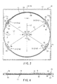
- a disc case 10 according to a first embodiment of the present invention will now be described with reference to FIGS. 1 to 6.
- the disc case 10 shown in FIG. 1 comprises a plastic tray 11 and a lid 13 that is swingably attached to the tray 11 by means of a hinge portion 12.
- the tray 11 is formed having a circular recess 14 that is shaped corresponding to the external shape of a disc D.
- the recess 14 includes a flat base portion 15 and a peripheral wall portion 16 around the base portion 15.
- Disc supporting portions 20 are formed on the peripheral wall portion 16. As shown in FIG. 4, the supporting portions 20 can carry thereon an outer peripheral portion D1 of the disc D in the recess 14 in a manner such that a recording surface D2 of the disc is floating.
- the supporting portions 20 are formed in a plurality of positions that are spaced in the circumferential direction of the recess 14.
- the supporting portions 20 may be replaced with a supporting portion that extends continuously in the circumferential direction of the recess 14.
- Spring portions 21 are provided in a plurality of positions located close to the peripheral wall portion 16 of the recess 14 and spaced in the circumferential direction of the recess. Since the spring portions 21 have their configuration and function in common, one of them will be described representatively. As shown in FIGS. 3 and 5, the spring portion 21 has a slot 22 that extends in the circumferential direction of the recess 14 and an arm-shaped spring element 25 that extends along the slot 22 between its opposite ends 23 and 24. Further, the spring portion 21 has a protuberance 26 formed near the upper end of the middle portion of the spring element with respect to its longitudinal direction and a slanting guide surface 27 formed on the outer side of the protuberance 26.
- a central portion 30 of the spring element 25 with respect to its longitudinal direction projects toward the inner part of the recess 14.
- the protuberance 26 is formed integrally with the central portion 30 of the spring element 25.
- the spring element 25 can bend in the diametrical direction of the disc D around the opposite ends 23 and 24 of the slot 22.
- the spring elements 25 push the outer peripheral portion D1 of the disc in the diametrical direction of the disc D, thereby the disc D is urged towards the center of the recess 14.
- the protuberance 26 can move in the direction indicated by arrow C in FIG. 6. More specifically, the protuberance 26 can move between a projecting position B1 in which it prevents the disc D from slipping out of the recess 14 and a position B2 in which it allows the disc D to be taken out.
- the plate shaped spring element 25 urges the protuberance 26 toward the projecting position B1.
- the spring portions 21 are located individually in four positions at given spaces in the circumferential direction of the peripheral wall portion 16 of the recess 14.
- Another pair of spring portions 21c and 21d that are situated nearer to the object side portion 11b of the tray 11 also adjoin each other at an angle ⁇ 2 (e.g., 60° or thereabout) narrower than 90° to each other.
- each spring portion 21 is liable to bend in the direction indicated by a segment L1 in FIG. 2.
- the plane shape of the recess 14 (taken as the tray 11 is viewed in its thickness direction) is the shape of an ellipse or oval that has its major axis extending along the segment L1 (along which each spring element 25 is liable to bend) and its minor axis extending along a segment L2 perpendicular to the segment L1.
- the major axis is longer than the minor axis by a dimension ⁇ L of several millimeters.
- the respective centers of circular arcs R1 and R2 that pass individually through the respective distal ends of the protuberances 26 are represented by C1 and C2, respectively.
- the distances (radii of curvature) from the centers C1 and C2 to the respective distal ends of the protuberances 26 are represented by r1 and r2, respectively.
- r1 and r2 are a little shorter than the radius of the disc D.
- the guide surface 27 is a slope such that it projects toward the disc D with distance from its top to the base portion 15 is increased. As the disc D is inserted into the recess 14, therefore, each spring element 25 bends in the direction to allow the insertion of the disc D with its guide surface 27 in contact with the outer peripheral portion D1 of the disc D.
- the disc case 10 of this embodiment unlike a conventional one, uses no center boss, so that its base portion 15 is substantially flat. If the tray 11 is formed of an optically transparent synthetic resin, therefore, the backside of the base portion 15 can be seen from the outside. If a beautifully designed printed surface is provided on the backside of the tray 11, moreover, the commercial value of the disc case 10 can be enhanced.
- An opening 40 that opens into the recess 14 is formed in the one side portion 11a of the tray 11.
- the opening 40 enables a user to catch or push the outer peripheral portion D1 of the disc D with his/her finger as he/she takes out the disc D from the recess 14.
- lugs 13b are formed inner side portions 13a of the lid 13. When the lid 13 is put on, the respective distal ends of the lugs 13b face the upper surface of the outer peripheral portion D1 of the disc D.
- FIGS. 15 to 18 individually show examples of the shape of each lug 13b.
- the lugs 13b shown in FIGS. 15 and 16 are reduced in thickness or tapered toward their respective distal ends 13d so that they have their respective slopes 13c on the underside.
- respective slopes 13c are slightly apart from the edge of the outer peripheral portion D1 of the disc.
- the disc D can be inserted into the recess 14 in the thickness direction of the tray 11 (indicated by arrows A in FIG. 1).
- the spring elements 25 bend so that the outer peripheral portion D1 of the disc D get inside the protuberances 26.
- the disc D is held in the recess 14, and the protuberances 26 are returned to their original projecting position by means of the elastic restoring force of the spring elements 25.
- the outer peripheral portion D1 of the disc D in the recess 14 is supported by means of the disc supporting portions 20.
- the recording surface D2 of the disc D is slightly lifted above the base portion 15 of the tray 11.
- the protuberances 26 prevent the disc D from slipping out of the tray 11.
- the lid 13 is closed, the respective distal ends of the lugs 13b face the outer peripheral portion D1 of the disc D. If a shock acts on the disc case 10, therefore, the lugs 13b can further effectively restrain the disc D from slipping out of the recess 14.
- the disc case 10 is designed so that the disc D can be inserted into the recess 14 in its thickness direction from above.
- an automatic loader that has been used in disc loading operation for conventional disc cases (cases with a center boss) can be used without modification.
- the disc D is kept horizontal by means of a vacuum suction mechanism or the like.
- the disc D can be set in the recess 14 by being simply inserted into the recess 14 from above the tray 11.
- the disc case 10 is provided with the spring elements 25 or plate springs that extend along the slots 22 in the tray 11. Therefore, each spring element 25 can enjoy so long an overall length W (shown in FIG. 3) that it easily bends in the diametrical direction of the disc D. Further, the flexibility of each spring element 25 can be adjusted according to its overall length W. Thus, the spring elements 25 can be made hard to break, so that their durability can be improved.
- the spring elements 25 of the disc case 10 can be made flexible, so that their durability can be improved despite the use of the relatively hard resin as the material of the tray 11.
- the material of the tray 11 may be selected freely, and an opaque resin may be used for the purpose.
- the spring portions 21c and 21d can be bent by pressing the disc D in the major-axis direction of the recess 14 (indicated by arrow P in FIG. 2). By doing this, the outer peripheral portion D1 of the disc D can be easily removed from the respective protuberances 26 of the spring portions 21a and 21b that are situated near the opening 40.
- the recess 14 has the shape of a perfect circle, a substantial gap is inevitably created between the outer peripheral portion D1 of the disc D and the peripheral wall portion 16 throughout the circumference of the disc D when the spring portions 21c and 21d are allowed to bend in the direction of arrow P in FIG. 2. This gap causes the disc D to shake in the recess 14.
- the recess 14 is in the shape of a moderate ellipse or oval, so that the spring elements 25 can fully bend in the direction of the major axis (segment L1) of the recess 14.
- the disc D can be prevented from moving in the direction of the miner axis (segment L2) of the recess 14.
- the disc D can be restrained from shaking in the recess 14.
- the disc D can be easily disengaged from the protuberances 26 as it is taken out of the recess 14.
- the side portion 11a of the tray 11 of this embodiment is formed having the opening 40 on the major axis (segment L1).
- the user softly pushes the disc D in the direction of arrow P with his/her finger on the outer peripheral portion D1 of the disc D at the opening 40.
- the spring portions 21c and 21d can be bent in the direction of arrow P, and the disc D can be easily disengaged from the respective protuberances 26 of the spring portions 21a and 21b.
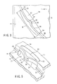
- FIG. 7 shows a disc case 10A according to a second embodiment of the invention.
- the disc case 10A of this embodiment comprises a tray 11 and a folding cover member 50 of cardboard.
- An example of the cover member 50 includes a mount portion 51 fixed to the second surface of a base portion 15 of the tray 11, a first cover portion 52 covering the first surface side of the tray 11, a second cover portion 53 capable of being put on the second surface side of the mount portion 51, etc. Since the basic configuration, function, and effect of the tray 11 of the second embodiment are the same as those of the tray 11 of the first embodiment, the common numeral is used to designate the two trays, and a description of the tray 11 of the second embodiment is omitted.
- the cover member 50 may alternatively be formed of a synthetic resin.
- the disc case 10A of the second embodiment patterns of desired designs can be beautifully printed on the cover member 50 by using an existing printing technique. If an optically transparent synthetic resin is used for the tray 11, the printed surface of the mount portion 51 can be seen through the base portion 15.
- the disc case 10A unlike a conventional one, uses no center boss, so that the beautiful printed surface of the mount portion 51 that is located on the under surface side of the transparent base portion 15 can be viewed clearly. Thus, the commercial value of the disc case 10A is enhanced.
- the spring elements 25 are expected only to have elasticity such that they can be deformed by being pushed by the outer peripheral portion D1 of the disc D as the disc D is inserted into the recess 14, and that they can be restored to their original state when the disc D is held in the recess 14.
- the spring elements 25 may be molded integrally with or separately from the tray 11.
- each spring portion 21 may be formed having a continuous arcuate shape.
- the protuberance 26 of each spring portion 21 may be tapered.
- each spring element 25 may be formed having a tapered protuberance 26 and a guide surface 27.
- a protuberance 26 and a guide surface 27 may be formed on the distal end portion of each spring element 25 that has a U-shaped sheet portion 55.
- a protuberance 26 and a guide surface 27 may be formed on the distal end portion of each spring element 25 that rises from the base portion 15 of the tray 11.
- the spring portions may be formed having various shapes.
- FIG. 11 shows a disc case 10B according to an eighth embodiment of the invention.
- spring portions 21c and 21d which are remote from an opening 40 have a shape such that they can bend deeper in the direction of the segment L1 than protuberances 26 of those spring portions 21a and 21b which are situated near the opening 40 can.
- the protuberances 26 of the spring portions 21c and 21d that are remote from the opening 40 are larger than the protuberances 26 of the spring portions 21a and 21b near the opening 40.
- the disc case 10B having these spring portions 21a to 21d cannot be easily disengaged from the spring portions 21a to 21d.
- the user can fully bend the spring portions 21c and 21d by applying force P to an end of the disc with his/her fingertip 60.
- the outer peripheral portion of the disc D can be easily disengaged from the protuberances 26 of the spring portions 21a and 21b that are situated near the opening 40 by bending the spring portions 21c and 21d that have a longer bending stroke.
- FIGS. 12 to 14 show a disc case 10C according to a ninth embodiment of the invention.
- a plurality of circular holes 71 are formed in a base 70 that is formed of cardboard, for example.
- Round trays 11' are fitted in the holes 71, individually.
- Each tray 11' shares its basic configuration and function with the tray 11 of the disc case 10B shown in FIG. 11 except for the following particulars.
- spring portions 21a, 21b and 21c are formed individually in three positions on the circumference of each tray 11'.
- Flange portions 75 that engage the upper side of the inner peripheral surface of each hole 71 in the base 70 and retaining protuberances 76 that can catch the inner peripheral surface of the hole 71 are formed on part of the tray 11' in its circumferential direction.
- the tray 11' like the tray 11, is formed of an optically transparent synthetic resin.
- the base 70 is provided with printed surfaces 72, on which beautifully designed patterns or pictures are printed. Among these printed surfaces 72, those ones which are situated on the backside of the base portion 15 of the tray 11' can be externally seen through the transparent base portion 15.
- FIG. 19 shows a disc case 10 according to a tenth embodiment of the present invention.
- This disc case 10 is provided with a pair of retaining protuberances 26a near the opening 40.
- a spring portion 21 is formed opposed to the opening 40.
- a pair of retaining protuberances 26b is formed near the spring portion 21. The protuberances 26a closer to the opening 40 are smaller than the protuberances 26b located near the spring portion 21.
- FIG. 20 shows a disc case 10 according to an eleventh embodiment of the present invention.
- This disc case 10 is provided with a pair of protuberance 26a near the opening 40.
- a protuberance 26b is formed opposed to the opening 40.
- a pair of spring portions 21 is formed near the protuberance 26b.
- the protuberances 26a and 26b are over-hanging so as to prevent the disc from slipping out of the recess 14.
- the trays having the recess 14 with an elliptic or oval plane shape have been described as preferred examples.
- the present invention is also applicable to trays with various other shapes. It is to be understood that the invention is applicable to a disc case using a tray that has a substantially perfectly circular recess, for example.
- the material and transparency of the trays may be selected freely, and in short, it is necessary only that the trays be shaped corresponding to media discs to be stored therein. It is to be understood that the respective configurations of the spring elements, protuberances, etc. and the number and location of the spring portions, as well as the respective configurations of the recess and the disc supporting portion(s), may be suitably changed or modified by one skilled in the art without departing from the scope of the invention.
Landscapes
- Packaging For Recording Disks (AREA)
- Packaging Of Annular Or Rod-Shaped Articles, Wearing Apparel, Cassettes, Or The Like (AREA)
Abstract
Description
- The present invention relates to a disc case used to store media discs, such as compact discs, so-called CD singles, digital versatile discs, etc.
- In a disc case that is conventionally used to store a media disc such as a compact disc, upper and lower plastic cases are swingably coupled to each other by means of hinge pivots, in general. A circular boss (center boss) is formed in the center of the lower case of the conventional disc case of this type. The disc is held in a manner such that its recording surface is floating as its center hole is fitted on the center boss.
- Disc cases that are used to store discs containing musical pieces, literature, etc. require peculiar, beautiful designs that distinguish those disc contents from others. If the center boss is formed on the base plate, as in the conventional disc case, however, it inevitably restricts the case design.
- Possibly, a flat base plate without a center boss may be used for the purpose. In this case, however, a protective sheet such as a nonwoven fabric must be used to protect the recording surface of a disc.
Thus, the number of indispensable components increases, and besides, the protective sheet spoils the beautiful appearance of the expressly designed base plate. - A proposed example of a disc case without a center boss is formed having an opening in a side face of its tray. A disc can be loaded into and unloaded from this disc case through the opening in the lateral direction of the tray. Conventional automatic disc loaders are designed so that they can insert the disc into the tray that is held horizontal from above the tray (in the thickness direction of the tray). Thus, the existing automatic disc loaders cannot be applied to disc cases that require the disc to be inserted in the lateral direction of the tray.
- Accordingly, the object of the present invention is to provide a disc case capable of holding a disc in a given position on a tray without using a center boss and preferably of allowing the disc to be loaded into and unloaded from the tray in the thickness direction of the disc.
- The present invention is set out in the independent claim. Some optional features are set out in the claims dependent thereto.
- A disc case according to one embodiment comprises a tray having a recess to be stored with a disc, a disc supporting portion formed on a peripheral wall portion of the recess and capable of supporting the outer peripheral portion of the disc in a manner such that the recording surface of the disc is floating, and spring portions provided near the peripheral wall portion. Each of the spring portions preferably may include a protuberance movable between a projecting position in which it prevents the disc from slipping out of the recess and a position in which it allows the disc to be taken out, a spring element for urging the protuberance toward the projecting position, and a guide surface adapted to touch the outer peripheral portion of the disc, thereby bending the spring element in a direction to allow the insertion of the disc into the recess, as the disc is inserted into the recess.
- When the disc case is stored with the disc, the outer peripheral portion of the disc touches the respective guide surfaces of the spring portions. As the spring elements bend, the outer peripheral of the disc moves into inside the protuberances, whereby the disc is set in the recess. The respective protuberances of the spring portions are restored to their original projecting position by means of the elastic force of the spring elements. The outer peripheral portion of the disc in the recess is supported by means of the disc supporting portion. Thus, the recording surface of the disc is slightly lifted above the base portion of the tray. Besides, the protuberances prevent the disc from slipping out of the tray.
- According to the present invention, the disc can be held in a given position on the tray with its recording surface floating without using a center boss. Since the disc case of the invention uses no center boss, restrictions on the design of the base portion of the tray are reduced. Further, the disc can be inserted into the recess in its thickness direction.
- According to this invention, each of the spring portions may include an arm-shaped spring element that extends along a slot in the tray and can bend around the opposite ends of the slot. In this case, the spring elements easily bend in the diametrical direction of the disc.
- Preferably, according to this invention, the tray is formed having an elliptic or oval recess. In taking out the disc, in this case, the disc can be easily disengaged from the protuberances by bending the spring elements in a manner such that its position is slightly shifted in the major-axis direction of the recess.
- Preferably, according to this invention, an opening is formed in a side portion of the tray. In taking out the disc from the recess, in this case, a user can push the spring elements by, for example, slightly shifting the position of the disc with his/her finger on the outer peripheral portion of the disc at the opening.
- According to another embodiment, a recess is formed in a tray of a disc case. A peripheral wall portion of the recess is formed having disc supporting portions that support a disc in a manner such that the recording surface of the disc is floating. Spring elements are arranged along slots that are formed in the peripheral wall portion. Each spring element is formed having a protuberance and a guide surface. As the disc is inserted into the recess, the spring elements bend with their respective guide surfaces touched by an outer peripheral portion of the disc. The outer peripheral portion moves into the space inside the protuberances of the spring elements. When the disc is in the recess, the protuberances prevent the disc from slipping out of the recess.
- The invention can be put into practice in several ways. Specific embodiments will now be described by way of example, with reference to the accompanying drawings in which:-
- FIG. 1 is a perspective view of a disc case according to a first embodiment of the present invention;
- FIG. 2 is a plan view of a tray of the disc case shown in FIG. 1;
- FIG. 3 is an enlarged plan view showing part of the tray shown in FIG. 2;
- FIG. 4 is a sectional view of the tray with a disc therein, taken along line F4-F4 of FIG. 2;
- FIG. 5 is an enlarged perspective view showing part of the tray shown in FIG. 2;
- FIG. 6 is an enlarged sectional view of a spring portion shown in FIG. 4;
- FIG. 7 is a perspective view of a disc case according to a second embodiment of the invention;
- FIG. 8A is a perspective view, partially in section, showing a spring portion according to a third embodiment of the invention;
- FIG. 8B is a perspective view, partially in section, showing a spring portion according to a fourth embodiment of the invention;
- FIG. 8C is a perspective view, partially in section, showing a spring portion according to a fifth embodiment of the invention;
- FIG. 9 is a perspective view, partially in section, showing a spring portion according to a sixth embodiment of the invention;
- FIG. 10 is a perspective view, partially in section, showing a spring portion according to a seventh embodiment of the invention;
- FIG. 11 is a plan view of a disc case according to an eighth embodiment of the invention;
- FIG. 12 is a perspective view of a disc case according to a ninth embodiment of the invention;
- FIG. 13 is a plan view of a tray of the disc case shown in FIG. 12;
- FIG. 14 is a sectional view of the tray taken along line F14-F14 of FIG. 13;
- FIG. 15 is a partial sectional view of the disc case shown in FIG. 1;
- FIGS. 16, 17 and 18 are partial sectional views of disc cases having differently modified lugs, individually;
- FIG. 19 is a plan view of a disc case according to a tenth embodiment of the present invention; and
- FIG. 20 is a plan view of a disc case according to an eleventh embodiment of the present invention.
-
- A
disc case 10 according to a first embodiment of the present invention will now be described with reference to FIGS. 1 to 6. - The
disc case 10 shown in FIG. 1 comprises aplastic tray 11 and alid 13 that is swingably attached to thetray 11 by means of ahinge portion 12. Thetray 11 is formed having acircular recess 14 that is shaped corresponding to the external shape of a disc D. Therecess 14 includes aflat base portion 15 and aperipheral wall portion 16 around thebase portion 15. -
Disc supporting portions 20 are formed on theperipheral wall portion 16. As shown in FIG. 4, the supportingportions 20 can carry thereon an outer peripheral portion D1 of the disc D in therecess 14 in a manner such that a recording surface D2 of the disc is floating. The supportingportions 20 are formed in a plurality of positions that are spaced in the circumferential direction of therecess 14. The supportingportions 20 may be replaced with a supporting portion that extends continuously in the circumferential direction of therecess 14. -
Spring portions 21 are provided in a plurality of positions located close to theperipheral wall portion 16 of therecess 14 and spaced in the circumferential direction of the recess. Since thespring portions 21 have their configuration and function in common, one of them will be described representatively. As shown in FIGS. 3 and 5, thespring portion 21 has aslot 22 that extends in the circumferential direction of therecess 14 and an arm-shapedspring element 25 that extends along theslot 22 between its opposite ends 23 and 24. Further, thespring portion 21 has aprotuberance 26 formed near the upper end of the middle portion of the spring element with respect to its longitudinal direction and a slantingguide surface 27 formed on the outer side of theprotuberance 26. - A
central portion 30 of thespring element 25 with respect to its longitudinal direction projects toward the inner part of therecess 14. Theprotuberance 26 is formed integrally with thecentral portion 30 of thespring element 25. Thespring element 25 can bend in the diametrical direction of the disc D around the opposite ends 23 and 24 of theslot 22. Thespring elements 25 push the outer peripheral portion D1 of the disc in the diametrical direction of the disc D, thereby the disc D is urged towards the center of therecess 14. - The
protuberance 26 can move in the direction indicated by arrow C in FIG. 6. More specifically, theprotuberance 26 can move between a projecting position B1 in which it prevents the disc D from slipping out of therecess 14 and a position B2 in which it allows the disc D to be taken out. The plate shapedspring element 25 urges theprotuberance 26 toward the projecting position B1. - In the case of the
tray 11 shown in FIG. 2, thespring portions 21 are located individually in four positions at given spaces in the circumferential direction of theperipheral wall portion 16 of therecess 14. Among the fourspring portions 21, a pair ofspring portions side portion 11a of thetray 11 than to theother side portion 11b adjoin each other at an angle 1 (e.g., 60° or thereabout) narrower than 90° to each other. Another pair ofspring portions 21c and 21d that are situated nearer to theobject side portion 11b of thetray 11 also adjoin each other at an angle 2 (e.g., 60° or thereabout) narrower than 90° to each other. Thus, eachspring portion 21 is liable to bend in the direction indicated by a segment L1 in FIG. 2. - The plane shape of the recess 14 (taken as the
tray 11 is viewed in its thickness direction) is the shape of an ellipse or oval that has its major axis extending along the segment L1 (along which eachspring element 25 is liable to bend) and its minor axis extending along a segment L2 perpendicular to the segment L1. In this embodiment, the major axis is longer than the minor axis by a dimension ΔL of several millimeters. - In FIG. 2, the respective centers of circular arcs R1 and R2 that pass individually through the respective distal ends of the
protuberances 26 are represented by C1 and C2, respectively. The distances (radii of curvature) from the centers C1 and C2 to the respective distal ends of theprotuberances 26 are represented by r1 and r2, respectively. When thespring elements 25 are subjected to no external force (or in a free state), r1 and r2 are a little shorter than the radius of the disc D. Theguide surface 27 is a slope such that it projects toward the disc D with distance from its top to thebase portion 15 is increased. As the disc D is inserted into therecess 14, therefore, eachspring element 25 bends in the direction to allow the insertion of the disc D with itsguide surface 27 in contact with the outer peripheral portion D1 of the disc D. - The
disc case 10 of this embodiment, unlike a conventional one, uses no center boss, so that itsbase portion 15 is substantially flat. If thetray 11 is formed of an optically transparent synthetic resin, therefore, the backside of thebase portion 15 can be seen from the outside. If a beautifully designed printed surface is provided on the backside of thetray 11, moreover, the commercial value of thedisc case 10 can be enhanced. - An
opening 40 that opens into therecess 14 is formed in the oneside portion 11a of thetray 11. Theopening 40 enables a user to catch or push the outer peripheral portion D1 of the disc D with his/her finger as he/she takes out the disc D from therecess 14. As shown in FIG. 1, lugs 13b are formedinner side portions 13a of thelid 13. When thelid 13 is put on, the respective distal ends of thelugs 13b face the upper surface of the outer peripheral portion D1 of the disc D. - FIGS. 15 to 18 individually show examples of the shape of each
lug 13b. Thelugs 13b shown in FIGS. 15 and 16 are reduced in thickness or tapered toward their respectivedistal ends 13d so that they have theirrespective slopes 13c on the underside. Usually,respective slopes 13c are slightly apart from the edge of the outer peripheral portion D1 of the disc. When the disc D is moved toward thelugs 13b by shock or the like, thelugs 13b touch only the edge of the outer peripheral portion D1 of the disc. Accordingly, if the disc D is turned upside down and the recording surface D2 of the disc faces on thelugs 13b, therefore, the recording surface D2 can be prevented from touching thelugs 13b. - The following is a description of the operation of the
disc case 10 according to this embodiment. - The disc D can be inserted into the
recess 14 in the thickness direction of the tray 11 (indicated by arrows A in FIG. 1). When the outer peripheral portion D1 of the disc D touches the respective guide surfaces 27 of thespring portions 21 as the disc D is inserted into therecess 14, thespring elements 25 bend so that the outer peripheral portion D1 of the disc D get inside theprotuberances 26. - Thus, the disc D is held in the
recess 14, and theprotuberances 26 are returned to their original projecting position by means of the elastic restoring force of thespring elements 25. The outer peripheral portion D1 of the disc D in therecess 14 is supported by means of thedisc supporting portions 20. The recording surface D2 of the disc D is slightly lifted above thebase portion 15 of thetray 11. Besides, theprotuberances 26 prevent the disc D from slipping out of thetray 11. When thelid 13 is closed, the respective distal ends of thelugs 13b face the outer peripheral portion D1 of the disc D. If a shock acts on thedisc case 10, therefore, thelugs 13b can further effectively restrain the disc D from slipping out of therecess 14. - The
disc case 10 is designed so that the disc D can be inserted into therecess 14 in its thickness direction from above. Thus, an automatic loader that has been used in disc loading operation for conventional disc cases (cases with a center boss) can be used without modification. In this automatic loader, the disc D is kept horizontal by means of a vacuum suction mechanism or the like. The disc D can be set in therecess 14 by being simply inserted into therecess 14 from above thetray 11. - The
disc case 10 is provided with thespring elements 25 or plate springs that extend along theslots 22 in thetray 11. Therefore, eachspring element 25 can enjoy so long an overall length W (shown in FIG. 3) that it easily bends in the diametrical direction of the disc D. Further, the flexibility of eachspring element 25 can be adjusted according to its overall length W. Thus, thespring elements 25 can be made hard to break, so that their durability can be improved. - The transparent resin for the
tray 11, e.g., polystyrene, ABS resin, or polyvinyl chloride, etc. that is doped with no softener, is harder than a resin that is doped with a softener. As described above, thespring elements 25 of thedisc case 10 can be made flexible, so that their durability can be improved despite the use of the relatively hard resin as the material of thetray 11. However, the material of thetray 11 may be selected freely, and an opaque resin may be used for the purpose. - In taking out the disc D from the
recess 14 of thedisc case 10, thespring portions 21c and 21d can be bent by pressing the disc D in the major-axis direction of the recess 14 (indicated by arrow P in FIG. 2). By doing this, the outer peripheral portion D1 of the disc D can be easily removed from therespective protuberances 26 of thespring portions opening 40. - If the
recess 14 has the shape of a perfect circle, a substantial gap is inevitably created between the outer peripheral portion D1 of the disc D and theperipheral wall portion 16 throughout the circumference of the disc D when thespring portions 21c and 21d are allowed to bend in the direction of arrow P in FIG. 2. This gap causes the disc D to shake in therecess 14. According to this embodiment, however, therecess 14 is in the shape of a moderate ellipse or oval, so that thespring elements 25 can fully bend in the direction of the major axis (segment L1) of therecess 14. The disc D can be prevented from moving in the direction of the miner axis (segment L2) of therecess 14. Thus, the disc D can be restrained from shaking in therecess 14. Further, the disc D can be easily disengaged from theprotuberances 26 as it is taken out of therecess 14. - The
side portion 11a of thetray 11 of this embodiment is formed having the opening 40 on the major axis (segment L1). In taking out the disc D from therecess 14, the user softly pushes the disc D in the direction of arrow P with his/her finger on the outer peripheral portion D1 of the disc D at theopening 40. By doing this, thespring portions 21c and 21d can be bent in the direction of arrow P, and the disc D can be easily disengaged from therespective protuberances 26 of thespring portions - FIG. 7 shows a
disc case 10A according to a second embodiment of the invention. Thedisc case 10A of this embodiment comprises atray 11 and afolding cover member 50 of cardboard. An example of thecover member 50 includes amount portion 51 fixed to the second surface of abase portion 15 of thetray 11, afirst cover portion 52 covering the first surface side of thetray 11, asecond cover portion 53 capable of being put on the second surface side of themount portion 51, etc. Since the basic configuration, function, and effect of thetray 11 of the second embodiment are the same as those of thetray 11 of the first embodiment, the common numeral is used to designate the two trays, and a description of thetray 11 of the second embodiment is omitted. Thecover member 50 may alternatively be formed of a synthetic resin. - In the
disc case 10A of the second embodiment, patterns of desired designs can be beautifully printed on thecover member 50 by using an existing printing technique. If an optically transparent synthetic resin is used for thetray 11, the printed surface of themount portion 51 can be seen through thebase portion 15. Thedisc case 10A, unlike a conventional one, uses no center boss, so that the beautiful printed surface of themount portion 51 that is located on the under surface side of thetransparent base portion 15 can be viewed clearly. Thus, the commercial value of thedisc case 10A is enhanced. - The
spring elements 25 are expected only to have elasticity such that they can be deformed by being pushed by the outer peripheral portion D1 of the disc D as the disc D is inserted into therecess 14, and that they can be restored to their original state when the disc D is held in therecess 14. In either of the foregoing embodiments, thespring elements 25 may be molded integrally with or separately from thetray 11. - As in the case of a third embodiment shown in FIG. 8A, for example, the
protuberance 26 and theguide surface 27 of eachspring portion 21 may be formed having a continuous arcuate shape. As in a fourth embodiment shown in FIG. 8B, moreover, theprotuberance 26 of eachspring portion 21 may be tapered. Alternatively, as in a fifth embodiment shown in FIG. 8C, eachspring element 25 may be formed having a taperedprotuberance 26 and aguide surface 27. These retainingprotuberances 26, like the ones according to the foregoing embodiment, are overhangs that project toward the inner part of therecess 14. - As in the case of a sixth embodiment shown in FIG. 9, moreover, a
protuberance 26 and aguide surface 27 may be formed on the distal end portion of eachspring element 25 that has aU-shaped sheet portion 55. Alternatively, as in a seventh embodiment shown in FIG. 10, aprotuberance 26 and aguide surface 27 may be formed on the distal end portion of eachspring element 25 that rises from thebase portion 15 of thetray 11. Thus, the spring portions may be formed having various shapes. - FIG. 11 shows a disc case 10B according to an eighth embodiment of the invention. Common numerals are used to designate common portions of the
disc cases 10 and 10B of the second and eighth embodiments, and a description of those portions is omitted. In the disc case 10B,spring portions 21c and 21d which are remote from anopening 40 have a shape such that they can bend deeper in the direction of the segment L1 thanprotuberances 26 of thosespring portions opening 40 can. Besides, theprotuberances 26 of thespring portions 21c and 21d that are remote from theopening 40 are larger than theprotuberances 26 of thespring portions opening 40. - If a shock acts on the disc case 10B having these
spring portions 21a to 21d, the disc cannot be easily disengaged from thespring portions 21a to 21d. In taking out the disc from thetray 11, moreover, the user can fully bend thespring portions 21c and 21d by applying force P to an end of the disc with his/herfingertip 60. Thus, the outer peripheral portion of the disc D can be easily disengaged from theprotuberances 26 of thespring portions opening 40 by bending thespring portions 21c and 21d that have a longer bending stroke. - FIGS. 12 to 14 show a
disc case 10C according to a ninth embodiment of the invention. As shown in FIG. 12, a plurality ofcircular holes 71 are formed in a base 70 that is formed of cardboard, for example. Round trays 11' are fitted in theholes 71, individually. Each tray 11' shares its basic configuration and function with thetray 11 of the disc case 10B shown in FIG. 11 except for the following particulars. - As shown in FIG. 13,
spring portions Flange portions 75 that engage the upper side of the inner peripheral surface of eachhole 71 in thebase 70 and retainingprotuberances 76 that can catch the inner peripheral surface of thehole 71 are formed on part of the tray 11' in its circumferential direction. The tray 11', like thetray 11, is formed of an optically transparent synthetic resin. Thebase 70 is provided with printedsurfaces 72, on which beautifully designed patterns or pictures are printed. Among these printedsurfaces 72, those ones which are situated on the backside of thebase portion 15 of the tray 11' can be externally seen through thetransparent base portion 15. - FIG. 19 shows a
disc case 10 according to a tenth embodiment of the present invention. Thisdisc case 10 is provided with a pair of retainingprotuberances 26a near theopening 40. Aspring portion 21 is formed opposed to theopening 40. A pair of retainingprotuberances 26b is formed near thespring portion 21. Theprotuberances 26a closer to theopening 40 are smaller than theprotuberances 26b located near thespring portion 21. - FIG. 20 shows a
disc case 10 according to an eleventh embodiment of the present invention. Thisdisc case 10 is provided with a pair ofprotuberance 26a near theopening 40. Aprotuberance 26b is formed opposed to theopening 40. A pair ofspring portions 21 is formed near theprotuberance 26b. Like theprotuberances 26 of the aforesaid embodiments, theprotuberances recess 14. - In connection with the foregoing embodiments, the trays having the
recess 14 with an elliptic or oval plane shape have been described as preferred examples. However, the present invention is also applicable to trays with various other shapes. It is to be understood that the invention is applicable to a disc case using a tray that has a substantially perfectly circular recess, for example. - In carrying out the present invention, the material and transparency of the trays may be selected freely, and in short, it is necessary only that the trays be shaped corresponding to media discs to be stored therein. It is to be understood that the respective configurations of the spring elements, protuberances, etc. and the number and location of the spring portions, as well as the respective configurations of the recess and the disc supporting portion(s), may be suitably changed or modified by one skilled in the art without departing from the scope of the invention.
Claims (8)
- A disc case comprising:a tray (11, 11') having a recess (14) to be stored with a disc; characterized bya disc supporting portion (20) formed on a peripheral wall portion (16) of the recess (14) and capable of supporting an outer peripheral portion of the disc in a manner such that a recording surface of the disc is floating;at least one spring portion (21) provided on the peripheral wall portion (16) of the tray (11, 11') in the circumferential direction thereof, each spring portion including a spring element (25) adapted to urge the outer peripheral portion of the disc in a diametrical direction of the disc, thereby bending the spring element (25) in a direction to allow the insertion of the disc into the recess (14), as the disc is inserted into the recess (14); anda protuberance (26, 26a, 26b) for preventing the disc from slipping out of the recess (14).
- A disc case according to claim 1,
characterized in that said tray (11, 11') is formed having a slot (22) extending in the circumferential direction of the peripheral wall portion (16), and said arm-shaped spring element (25) extends along the slot (22) between the opposite ends thereof and is formed integrally with the tray (11, 11'), the spring element (25) being formed having the protuberance (26) and the guide surface (27). - A disc case according to claim 1,
characterized in that said recess (14) is shaped along an ellipse or oval having a major axis (L1) extending in a direction in which the spring element (25) can bend and a minor axis (L2) extending at right angles to the major axis (L1). - A disc case according to claim 1,
characterized in that said tray (11, 11') is formed having, in a side portion thereof, an opening (40) communicating with the recess (14) and serving to enable a user to touch the outer peripheral portion of the disc with his/her finger as the user takes out the disc from the recess (14). - A disc case according to claim 3,
characterized in that said tray (11, 11') is formed having, in a side portion thereof, an opening (40) communicating with the recess (14) and serving to enable a user to touch the outer peripheral portion of the disc with his/her finger as the user takes out the disc from the recess (14). - A disc case according to claim 5,
characterized in that spring portions (21c, 21d) which are remote from the opening (40) have a shape such that the spring portions (21c, 21d) can bend deeper in the diametrical direction of the disc than
spring portions (21a, 21b) which are situated near the opening (40). - A disc case according to claim 6,
characterized in that said respective protuberances (26) of the spring portions (21c, 21d) that are remote from the opening (40) are larger than the respective protuberances (26) of the spring portions (21a, 21b) that are situated near the opening (40). - A disc case according to claim 1,
characterized in that said tray (11, 11') is formed of an optically transparent synthetic resin and is provided, in the backside thereof, with printed matter (51, 70) printed with a picture(s), pattern(s), and/or character(s).
Applications Claiming Priority (2)
| Application Number | Priority Date | Filing Date | Title |
|---|---|---|---|
| JP2000284071 | 2000-09-19 | ||
| JP2000284071A JP3828734B2 (en) | 2000-09-19 | 2000-09-19 | Disc case |
Publications (1)
| Publication Number | Publication Date |
|---|---|
| EP1189233A1 true EP1189233A1 (en) | 2002-03-20 |
Family
ID=18768348
Family Applications (1)
| Application Number | Title | Priority Date | Filing Date |
|---|---|---|---|
| EP01308002A Withdrawn EP1189233A1 (en) | 2000-09-19 | 2001-09-19 | Disc case |
Country Status (8)
| Country | Link |
|---|---|
| US (1) | US6837370B2 (en) |
| EP (1) | EP1189233A1 (en) |
| JP (1) | JP3828734B2 (en) |
| KR (1) | KR100439435B1 (en) |
| CN (1) | CN1133168C (en) |
| CA (1) | CA2357424C (en) |
| SG (1) | SG115403A1 (en) |
| TW (1) | TWI233911B (en) |
Cited By (6)
| Publication number | Priority date | Publication date | Assignee | Title |
|---|---|---|---|---|
| NL1021519C2 (en) * | 2002-08-06 | 2004-02-10 | Fountain Tech Bv | Plate-shaped information carrier e.g. compact disc packaging device, has receiving unit with two locking units provided on closing surface of cover part, where two locking units extend along outer contour of carrier |
| WO2004013860A1 (en) * | 2002-08-06 | 2004-02-12 | Fountain Technologies B.V. | Packaging device for cd's dvd's information cards and the like |
| FR2846774A1 (en) * | 2002-11-05 | 2004-05-07 | Francis Laroche | Disc e.g. digital versatile disc conditioning case, is made of plate with radial shoulders to recover marginal area of disc, where shoulders allow disc insertion and removal by elastic deformation of plate part having thrust washer |
| WO2005008670A1 (en) * | 2003-07-21 | 2005-01-27 | Tri-Tec Industries, Ltd. | Packaging for disc-type media |
| FR2871919A1 (en) * | 2004-06-17 | 2005-12-23 | Montreuil Offset Sa | PACKAGING FOR DIGITAL DISCS STOCKED IN OBLIQUE |
| WO2006134383A1 (en) * | 2005-06-17 | 2006-12-21 | Agi Media Packaging Europe Limited | Apparatus for holding a disk |
Families Citing this family (23)
| Publication number | Priority date | Publication date | Assignee | Title |
|---|---|---|---|---|
| US6719133B2 (en) * | 2001-10-19 | 2004-04-13 | Panasonic Disc Manufacturing Corporation Of America | Security storage container |
| FR2846775B1 (en) * | 2002-11-05 | 2006-11-24 | Francis Laroche | PACKAGING FOR DIGITAL RECORDING RECORDING MEDIUM |
| SI1614116T1 (en) * | 2003-02-28 | 2007-10-31 | Koninkl Philips Electronics Nv | Housing for a disc-shaped information carrier |
| US6929123B2 (en) * | 2003-03-14 | 2005-08-16 | Finest Industrial Co., Ltd. | Security disk case |
| US20040195465A1 (en) * | 2003-04-04 | 2004-10-07 | Alain Crouan | CD case support method and apparatus |
| US7066327B2 (en) * | 2003-12-17 | 2006-06-27 | Black & Decker Inc. | Saw blade packaging |
| JP4150366B2 (en) * | 2004-03-12 | 2008-09-17 | 株式会社ソニー・コンピュータエンタテインメント | Disc container and information provider |
| US20050236284A1 (en) * | 2004-04-23 | 2005-10-27 | Infiniti Media, Inc. | Apparatus for holding a media storage disk |
| US20050274632A1 (en) * | 2004-06-09 | 2005-12-15 | Tien-Lai Lin | Optical disk container with writing tool holding device |
| US7011211B1 (en) * | 2005-02-07 | 2006-03-14 | Halin Enterprise Co., Ltd. | Storage container for an appendage of a compact disc |
| US7376960B2 (en) * | 2005-03-02 | 2008-05-20 | Ming-Hsun Liu | Compact disc receptacle and compact disc processing system |
| US20060196789A1 (en) * | 2005-03-03 | 2006-09-07 | O'brien Patrick | Tray for retaining a recording disc |
| US20090178941A1 (en) * | 2005-08-18 | 2009-07-16 | Gelardi John A | Package for Universal Media Disc |
| KR100757051B1 (en) * | 2006-04-04 | 2007-09-07 | 박노경 | Optical record carrier case |
| US20070241005A1 (en) * | 2006-04-14 | 2007-10-18 | Maxine Liang | Laser disc casing device |
| WO2008124115A1 (en) * | 2007-04-06 | 2008-10-16 | Meadwestvaco Corporation | Dics package with securing ledges |
| JP5147285B2 (en) * | 2007-05-11 | 2013-02-20 | 株式会社ソニー・コンピュータエンタテインメント | Disk housing and disk device |
| CN101767691B (en) * | 2009-01-06 | 2012-01-25 | 卢安东 | Optical disc storage box |
| JP4447050B1 (en) * | 2009-07-27 | 2010-04-07 | 斎藤合成樹脂工業株式会社 | Storage case for small items |
| US8662296B2 (en) * | 2011-04-21 | 2014-03-04 | Atlas Agi Holdings, Llc | Booklet form paperboard package for media discs |
| TWI473202B (en) * | 2011-12-19 | 2015-02-11 | 財團法人工業技術研究院 | Carrying device and substrate unloading method using same |
| CN110395487B (en) | 2019-08-02 | 2020-11-17 | 精密产品有限公司 | Multimedia storage carrier packaging container |
| JP7615670B2 (en) * | 2020-12-25 | 2025-01-17 | セイコーエプソン株式会社 | Recording device |
Citations (6)
| Publication number | Priority date | Publication date | Assignee | Title |
|---|---|---|---|---|
| EP0252226A1 (en) * | 1986-06-09 | 1988-01-13 | International Business Machines Corporation | Disk retainer and packaging system for optical disks |
| US4850731A (en) * | 1988-05-06 | 1989-07-25 | Youngs Ross O | Compact disc storage container with non-scratching surface |
| FR2729248A1 (en) * | 1995-01-11 | 1996-07-12 | Mathieu Bruno | Compact disc storage case with improved disc location in box |
| US5704474A (en) * | 1996-12-02 | 1998-01-06 | Oland; Charles Jeffrey | Disc carrier |
| US6077583A (en) * | 1998-03-03 | 2000-06-20 | Park; Arnold | Digital information guard |
| EP1014374A1 (en) * | 1998-12-21 | 2000-06-28 | Cartonneries De Thulin S.A. | Closable storage container for circular informationcarrier, especially a Compact Disc storing digital information |
Family Cites Families (10)
| Publication number | Priority date | Publication date | Assignee | Title |
|---|---|---|---|---|
| ATE60157T1 (en) * | 1985-01-07 | 1991-02-15 | Polygram Int Holding | TRAY FOR ACCOMMODATING AND HOLDING A RIGID CIRCULAR INFORMATION PLATE AND COMBINING SUCH TRAY WITH A STORAGE CASSETTE. |
| JP2814489B2 (en) | 1988-04-07 | 1998-10-22 | 凸版印刷株式会社 | Optical disc container |
| US5253751A (en) * | 1991-10-23 | 1993-10-19 | Sony Music Entertainment Inc. | Packaging for compact discs |
| US5284243A (en) * | 1992-10-21 | 1994-02-08 | Lakewood Industries, Inc. | Insertable tray for providing a multiple disc container |
| US5289918A (en) * | 1993-05-10 | 1994-03-01 | Scott Dobias | Container for compact discs |
| US5533615A (en) * | 1994-12-30 | 1996-07-09 | Mccamy; William G. | Disc storage case |
| US5730283A (en) * | 1995-07-03 | 1998-03-24 | Autronic Plastics, Inc. | Package and storage unit for digital information storage media |
| US5788069A (en) * | 1996-06-27 | 1998-08-04 | Westvaco Corporation | CD holder with spring |
| JP3692189B2 (en) | 1996-09-30 | 2005-09-07 | 北野エンジニアリング株式会社 | Disc case |
| JPH10310184A (en) | 1997-05-12 | 1998-11-24 | Rihito Rabu:Kk | Disk holding plate |
-
2000
- 2000-09-19 JP JP2000284071A patent/JP3828734B2/en not_active Expired - Fee Related
-
2001
- 2001-09-07 SG SG200105493A patent/SG115403A1/en unknown
- 2001-09-17 US US09/953,996 patent/US6837370B2/en not_active Expired - Fee Related
- 2001-09-17 KR KR10-2001-0057167A patent/KR100439435B1/en not_active Expired - Fee Related
- 2001-09-17 CN CN01141741A patent/CN1133168C/en not_active Expired - Fee Related
- 2001-09-18 CA CA002357424A patent/CA2357424C/en not_active Expired - Fee Related
- 2001-09-19 TW TW090123427A patent/TWI233911B/en not_active IP Right Cessation
- 2001-09-19 EP EP01308002A patent/EP1189233A1/en not_active Withdrawn
Patent Citations (6)
| Publication number | Priority date | Publication date | Assignee | Title |
|---|---|---|---|---|
| EP0252226A1 (en) * | 1986-06-09 | 1988-01-13 | International Business Machines Corporation | Disk retainer and packaging system for optical disks |
| US4850731A (en) * | 1988-05-06 | 1989-07-25 | Youngs Ross O | Compact disc storage container with non-scratching surface |
| FR2729248A1 (en) * | 1995-01-11 | 1996-07-12 | Mathieu Bruno | Compact disc storage case with improved disc location in box |
| US5704474A (en) * | 1996-12-02 | 1998-01-06 | Oland; Charles Jeffrey | Disc carrier |
| US6077583A (en) * | 1998-03-03 | 2000-06-20 | Park; Arnold | Digital information guard |
| EP1014374A1 (en) * | 1998-12-21 | 2000-06-28 | Cartonneries De Thulin S.A. | Closable storage container for circular informationcarrier, especially a Compact Disc storing digital information |
Cited By (9)
| Publication number | Priority date | Publication date | Assignee | Title |
|---|---|---|---|---|
| NL1021519C2 (en) * | 2002-08-06 | 2004-02-10 | Fountain Tech Bv | Plate-shaped information carrier e.g. compact disc packaging device, has receiving unit with two locking units provided on closing surface of cover part, where two locking units extend along outer contour of carrier |
| WO2004013860A1 (en) * | 2002-08-06 | 2004-02-12 | Fountain Technologies B.V. | Packaging device for cd's dvd's information cards and the like |
| FR2846774A1 (en) * | 2002-11-05 | 2004-05-07 | Francis Laroche | Disc e.g. digital versatile disc conditioning case, is made of plate with radial shoulders to recover marginal area of disc, where shoulders allow disc insertion and removal by elastic deformation of plate part having thrust washer |
| WO2005008670A1 (en) * | 2003-07-21 | 2005-01-27 | Tri-Tec Industries, Ltd. | Packaging for disc-type media |
| FR2871919A1 (en) * | 2004-06-17 | 2005-12-23 | Montreuil Offset Sa | PACKAGING FOR DIGITAL DISCS STOCKED IN OBLIQUE |
| WO2006005851A1 (en) * | 2004-06-17 | 2006-01-19 | Montreuil Offset | Packaging for digital obliquely stored discs |
| GB2429969A (en) * | 2004-06-17 | 2007-03-14 | Montreuil Offset | Packaging for digital obliquely stored discs |
| GB2429969B (en) * | 2004-06-17 | 2007-12-19 | Montreuil Offset | Packaging for digital obliquely stored discs |
| WO2006134383A1 (en) * | 2005-06-17 | 2006-12-21 | Agi Media Packaging Europe Limited | Apparatus for holding a disk |
Also Published As
| Publication number | Publication date |
|---|---|
| TWI233911B (en) | 2005-06-11 |
| CA2357424A1 (en) | 2002-03-19 |
| CN1133168C (en) | 2003-12-31 |
| JP3828734B2 (en) | 2006-10-04 |
| US20020033349A1 (en) | 2002-03-21 |
| SG115403A1 (en) | 2005-10-28 |
| KR20020022577A (en) | 2002-03-27 |
| CN1345066A (en) | 2002-04-17 |
| CA2357424C (en) | 2004-05-04 |
| US6837370B2 (en) | 2005-01-04 |
| KR100439435B1 (en) | 2004-07-09 |
| JP2002096885A (en) | 2002-04-02 |
Similar Documents
| Publication | Publication Date | Title |
|---|---|---|
| CA2357424C (en) | Disc case | |
| US5400902A (en) | Universal compact disc storage unit | |
| US6732859B2 (en) | Recording medium disc storage case and a recording medium disc | |
| US6749061B2 (en) | Compact disc carrying container | |
| US20090103251A1 (en) | Operation device and image recording device | |
| CN1327429A (en) | Petals with radially deflectable jaw ends for holding disc-shaped elements | |
| JPH05112383A (en) | Housing case for disc cartridge | |
| US5383553A (en) | Case for receiving at least one data storage disk | |
| US5394981A (en) | Hinged storage container for computer diskettes and documentation | |
| US7753200B2 (en) | Disk containing body and information providing body | |
| RU2371788C2 (en) | Container for disc-shaped digital record medium | |
| JP4057219B2 (en) | Disc case | |
| US6123190A (en) | Disc cartridge storage case | |
| EP1899973B1 (en) | Apparatus for holding a disk | |
| JP2004090952A (en) | Storage case for disklike recording medium | |
| AU775419B2 (en) | Apparatus for holding a compact disk | |
| JP3865216B2 (en) | Disc storage case | |
| JP4025765B2 (en) | Disc case and books | |
| EP2390882A1 (en) | Multi disc tray | |
| GB2317376A (en) | Holder for flat articles, particularly compact discs or floppy discs. | |
| JP2651900B2 (en) | Optical disk storage | |
| KR200300841Y1 (en) | Mouse pad | |
| JP2003054675A (en) | Data disk storage case | |
| WO2000047496A1 (en) | Improved compact disk jewel case | |
| JP2000103430A (en) | Container |
Legal Events
| Date | Code | Title | Description |
|---|---|---|---|
| PUAI | Public reference made under article 153(3) epc to a published international application that has entered the european phase |
Free format text: ORIGINAL CODE: 0009012 |
|
| 17P | Request for examination filed |
Effective date: 20011003 |
|
| AK | Designated contracting states |
Kind code of ref document: A1 Designated state(s): DE FR GB IT SE Kind code of ref document: A1 Designated state(s): AT BE CH CY DE DK ES FI FR GB GR IE IT LI LU MC NL PT SE TR |
|
| AX | Request for extension of the european patent |
Free format text: AL;LT;LV;MK;RO;SI |
|
| AKX | Designation fees paid |
Free format text: DE FR GB IT SE |
|
| 17Q | First examination report despatched |
Effective date: 20080415 |
|
| STAA | Information on the status of an ep patent application or granted ep patent |
Free format text: STATUS: THE APPLICATION IS DEEMED TO BE WITHDRAWN |
|
| 18D | Application deemed to be withdrawn |
Effective date: 20100401 |