EP1189225A2 - Seek trajectory adaptation in sinusoidal seek servo hard disk drives - Google Patents
Seek trajectory adaptation in sinusoidal seek servo hard disk drives Download PDFInfo
- Publication number
- EP1189225A2 EP1189225A2 EP01122139A EP01122139A EP1189225A2 EP 1189225 A2 EP1189225 A2 EP 1189225A2 EP 01122139 A EP01122139 A EP 01122139A EP 01122139 A EP01122139 A EP 01122139A EP 1189225 A2 EP1189225 A2 EP 1189225A2
- Authority
- EP
- European Patent Office
- Prior art keywords
- seek
- velocity
- track
- transducer
- percent
- Prior art date
- Legal status (The legal status is an assumption and is not a legal conclusion. Google has not performed a legal analysis and makes no representation as to the accuracy of the status listed.)
- Withdrawn
Links
Images


Classifications
-
- G—PHYSICS
- G11—INFORMATION STORAGE
- G11B—INFORMATION STORAGE BASED ON RELATIVE MOVEMENT BETWEEN RECORD CARRIER AND TRANSDUCER
- G11B21/00—Head arrangements not specific to the method of recording or reproducing
- G11B21/02—Driving or moving of heads
- G11B21/10—Track finding or aligning by moving the head ; Provisions for maintaining alignment of the head relative to the track during transducing operation, i.e. track following
-
- G—PHYSICS
- G11—INFORMATION STORAGE
- G11B—INFORMATION STORAGE BASED ON RELATIVE MOVEMENT BETWEEN RECORD CARRIER AND TRANSDUCER
- G11B5/00—Recording by magnetisation or demagnetisation of a record carrier; Reproducing by magnetic means; Record carriers therefor
- G11B5/48—Disposition or mounting of heads or head supports relative to record carriers ; arrangements of heads, e.g. for scanning the record carrier to increase the relative speed
- G11B5/54—Disposition or mounting of heads or head supports relative to record carriers ; arrangements of heads, e.g. for scanning the record carrier to increase the relative speed with provision for moving the head into or out of its operative position or across tracks
- G11B5/55—Track change, selection or acquisition by displacement of the head
- G11B5/5521—Track change, selection or acquisition by displacement of the head across disk tracks
- G11B5/5526—Control therefor; circuits, track configurations or relative disposition of servo-information transducers and servo-information tracks for control thereof
- G11B5/553—Details
- G11B5/5547—"Seek" control and circuits therefor
Definitions
- the present invention relates generally to disk drives and more particularly to a method, apparatus, and computer readable program product for improving the performance of hard disk drive servomechanisms.
- Hard disk drives include a plurality of magnetic transducers that can write and read information by magnetizing and sensing the magnetic field of a rotating disk(s), respectively.
- the information is typically formatted into a plurality of sectors that are located within an annular track.
- a number of vertically similar tracks are sometimes referred to as a cylinder. Each track may therefore be identified by a cylinder number.
- Each transducer is typically integrated into a slider that is incorporated into a head gimbal assembly (HGA).
- HGA head gimbal assembly
- Each HGA is attached to an actuator arm.
- the actuator arm has a voice coil located adjacent to a magnet assembly which together define a voice coil motor.
- the hard disk drive typically includes a driver circuit and a controller that provide current to excite the voice coil motor.
- the excited voice coil motor rotates the actuator arm and moves the transducers across the surfaces of the disk(s).
- the hard disk drive may perform a seek routine to move the transducers from one cylinder (track) to another cylinder.
- the voice coil motor is excited with a current to move the transducers to the new cylinder location on the disk surfaces.
- the controller also performs a servo routine to insure that the transducer is at the center of the track.
- the assignee of the present invention has introduced disk drives that utilize a sinusoidal seek algorithm where the transducer is moved according to a sinusoidal trajectory.
- the present invention comprises a method, apparatus, and computer program product for a hard disk drive.
- the apparatus comprises a disk which has a surface, a spindle motor to rotate the disk, a transducer to write information onto the disk and read information from the disk, an actuator arm to move the transducer across the surface of the disk, and a controller.
- the controller in response to a command to seek from a first track to a second track, can determine a seek length from the first track to the second track, determine a seek time based on the seek length, scale the seek time in response to a velocity error between a calculated velocity and a design velocity for the seek length, and control the actuator arm to move said transducer across said disk surface from the first track to the second track using an acceleration trajectory.
- a hard disk drive includes a disk which has a surface, a spindle motor that rotates the disk, and a transducer which can write information onto the disk and read information from the disk.
- the transducer may be integrated into a slider that is incorporated into a head gimbal assembly (HGA).
- Th HGA may be mounted to an actuator arm which can move the transducer across the disk surface. The movement of the actuator arm and the transducer may be controlled by a controller.
- the controller may move the transducer from a present track to a new track in accordance with a seek routine and a servo control routine.
- the controller can determine a seek length from the first track to the second track, determine a seek time based on the seek length, adjust the seek time in response to a velocity error between a calculated velocity and a design velocity for the seek length, and control the actuator arm to move the transducer across the disk surface from the present track to the new track using the acceleration trajectory.
- the acceleration trajectory is a sinusoidal acceleration trajectory.
- the acceleration trajectory may take other forms such as a bang-bang acceleration trajectory.
- Figure 1 shows an embodiment of a hard disk drive 10.
- the drive 10 includes at least one magnetic disk 12 that is rotated by a spindle motor 14.
- the drive 10 may also include a transducer 16 located adjacent to a disk surface 18.
- the transducer 16 can write and read information on the rotating disk 12 by magnetizing and sensing the magnetic field of the disk 12, respectively. There is typically a transducer 16 associated with each disk surface 18. Although a single transducer 16 is shown and described, it is to be understood that there may be a write transducer for magnetizing the disk 12 and a separate read transducer for sensing the magnetic field of the disk 12.
- the read transducer may be constructed from a magneto-resistive (MR) material.
- the transducer 16 can be integrated into a slider 20.
- the slider 20 may be constructed to create an air bearing between the transducer 16 and the disk surface 18.
- the slider 20 may be incorporated into a head gimbal assembly (HGA) 22.
- the HGA 22 may be attached to an actuator arm 24 which has a voice coil 26.
- the voice coil 26 may be located adjacent to a magnet assembly 28 to define a voice coil motor (VCM) 30.
- VCM voice coil motor
- Each track 34 typically contains a plurality of sectors. Each sector may include a data field and an identification field.
- the identification field may contain Gray code information which identifies the sector and track (cylinder).
- the transducer 16 is moved across the disk surface 18 to write or read information on a different track. Moving the transducer to access a different track is commonly referred to as a seek routine.
- FIG. 2 shows an electrical system 40 which can control the hard disk drive 10.
- the system 40 may include a controller 42 that is coupled to the transducer 16 by a read/write (R/W) channel circuit 44 and a pre-amplifier circuit 46.
- the controller 42 may be a digital signal processor (DSP), microprocessor, microcontroller, and the like.
- DSP digital signal processor
- the controller 42 can provide control signals to the read/write channel 44 to read from the disk 12 or write information to the disk 12.
- the information is typically transferred from the R/W channel 44 to a host interface circuit 46.
- the host circuit 46 may include buffer memory and control circuitry which allow the disk drive to interface with a system such as a personal computer.
- the controller 42 may also be coupled to a VCM driver circuit 48 which provides a driving current to the voice coil 26.
- the controller 42 may provide control signals to the driver circuit 48 to control the excitation of the VCM and the movement of the transducer 16.
- the controller 42 may be connected to a non-volatile memory such as a read only memory (ROM) or flash memory device 50, and a random access memory (RAM) device 52.
- the memory devices 50 and 52 may contain instructions and data that are used by the controller 42 to perform software routines.
- One of the software routines may be a seek routine to move the transducer 16 from one track to another track.
- the seek routine may include a servo control routine to insure that the transducer 16 moves to the correct track.
- the memory device 50 contains the acceleration, velocity, and position trajectory equations, as discussed hereinbelow, where such equations may be loaded into memory device 52 at startup.
- the memory device 50 may include one or more software routines that allow(s) for adaptation of the seek trajectory and one or more tables, all of which may be loaded into the memory device 52 at startup.
- Figure 3 shows a servo control system 60 that is implemented by the controller 42, which may be implemented in hardware and/or software.
- the servo control system 60 insures that the transducer 16 is accurately located on a desired track of the disk 12.
- the controller 42 performs a seek routine the transducer 16 is moved from a first track to a new track located a distance X SK from the first track.
- the Gray codes of one or more tracks located between the new and first tracks are read as the transducer 16 moves across the disk 16. This allows the controller 42 to periodically determine whether the transducer 16 is moving at a desired speed or acceleration, or both, across the disk surface.
- the control system 60 includes an estimator 62, which may be implemented in software and/or hardware.
- the estimator 62 can determine the actual distance or position X a that the transducer has moved from the first track. The position can be determined by reading the Gray code of a track beneath the transducer 16.
- the estimator 62 can also determine the actual velocity V a and actual acceleration A a of the transducer 16.
- the Gray codes can be periodically sampled as the transducer 16 moves to the new track location so that the controller 42 can correct the movement of the transducer 16 with the control system 60.
- the controller 42 computes a design position X i , a design velocity V i and a design acceleration A i of the transducer 16 each time the transducer reads the Gray code of a track 34.
- the controller 42 computes the difference between the design position X i and the actual position X a at summing junction 64.
- the controller 42 then computes a position correction value E x with a proportional plus integral control algorithm and the output of the summing junction 64.
- the actual velocity V a is subtracted from the sum of the design velocity V i and the position correction value E x at summing junction 68.
- the controller 42 computes a velocity correction value E v with a proportional plus integral control algorithm and the output of the summing junction 68.
- An acceleration correction value E a is computed by subtracting the actual acceleration A a from the sum of the design acceleration A i and the velocity correction value E v at summing junction 72.
- the acceleration correction value E a is used to increase or decrease the current provided to the voice coil 26 and to vary the acceleration of the movement of the transducer 16.
- the acceleration correction value E a may also be provided to the estimator 62 to generate a feedforward acceleration value A' a .
- the feedforward acceleration value A' a can be provided to summing junction 72 to provide a feedforward control loop.
- the acceleration trajectory comprises a sinusoidal acceleration trajectory, as defined by the following equation: where;
- the following ideal velocity equation can be derived by integrating the acceleration equation.
- Figures 4A through 4C show exemplary graphs of the acceleration, velocity, and position trajectories of a sinusoidal seek.
- the disk drive may receive a command to store or read information.
- the command may require that the transducer be moved from a first track to a new track in accordance with a seek routine.
- the new track and corresponding distance (seek length X SK ) to the new track from the first track can be determined by the controller 42.
- the seek time may be initially computed before the ideal acceleration, ideal velocity, and ideal position are computed.
- T SK 2 ⁇ X SK K A I M .
- T SK T I SK + T I +1 SK - T I SK X I +1 SK - X I SK ( X SK - X I SK ).
- Table 1 provides an exemplary format of the X sk v. T sk lookup table. I 1 2 3 ... N X sk X sk1 X sk2 X sk3 ... X skN T sk T sk1 T sk2 T sk3 ... T skN
- the system may take a number of samples which correlate to the different positions, velocities, and accelerations of the transducer as the transducer moves from one track to another track. It is desirable to discretize the ideal trajectories to correspond with the sampling of Gray codes so that the actual values can be subtracted from the ideal values at the summing junctions of the servo control shown in Figure 3. To discretize the trajectories, equations (1), (2), and (3) are transformed into a sample domain (n) and equation (4) is substituted into the amplitude terms to generate the following equations. and where;
- the controller 42 computes the ideal position, ideal velocity, and ideal acceleration of the transducer at a first sample time, determines the actual position, velocity, and acceleration values and then processes the data in accordance with the control loop shown in Fig. 3 and described above. Second, third, etc. samples are taken and the process is repeated to provide a servo routine that controls the movement of the transducer 16.
- T CST X SK - X M SK V MAX .
- the controller computes the ideal position, ideal velocity, and ideal acceleration in accordance with equations (15) through (27), and then utilizes the ideal values in the control loop of Fig. 3.
- the disk drive During normal operation, the disk drive exhibits good seek performance using the sinusoidal seek method. In extreme conditions, however, such as, for example, when the disk drive is subjected to high temperature or is operated in a low voltage environment, the disk drive may exhibit a seek overrun condition. For example, at high temperatures, the resistance of the voice coil motor tends to increase causing a larger voltage drop across the voice coil motor, and thus a smaller voltage to drive the obtained current command E a . As a result, a voltage saturation condition arises resulting in a different VCM current from the current command E a . This can cause overshoot during settling.
- the present invention adaptively adjusts the seek time based on the available voltage. Since the available voltage may be hard to determine, the seek time is adaptively adjusted based on the voltage error signal V err . If there is sufficient voltage to drive the VCM, the VCM current is substantially the same as the current command E a . In this case, the actual velocity is substantially the same as the velocity profile calculated from the current command. Consequently, the maximum of velocity error V err between the actual velocity and design velocity will be below a selectable threshold THLD 1 . However, if there is not sufficient voltage to drive the VCM, the actual VCM current is different than the design current, and the actual velocity is different than the design velocity.
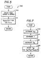
- FIG. 5 illustrates a flow diagram of an initialization method 500, according to one embodiment of the present invention.
- the initialization method is typically executed during power on self-test, or at some time prior to operation of the adaptive technique.
- the method 500 commences at block 510 where a K scale table having N entries is created in memory (e.g., memory 52, Figure 2).
- the size of the K scale table is equal to the size of Table 1.
- all entries in the K scale table are set to one.
- the K scale table may be part of Table 1.
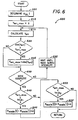
- Figure 6 illustrates a flow diagram of a method 600 for adjusting a scaling value, according to one embodiment of the present invention.
- the method 600 is executed for each seek.
- the maximum velocity error V err is calculated and compared with two thresholds. If V err is larger than a first threshold THLD 1 , K scale is increased to provide a slower seek time. On the other hand, if V err is smaller than a second threshold THLD 2 , K scale is decreased to provide faster seek time.
- the method 600 commences at block 605 where X sk and I are determined.
- X sk which is the distance between a current track and a new track, may be determined by table lookup. Once X sk is determined, I is determined from Table 1. For example, if X sk is equal to the fifth entry in Table 1 (X sk5 ), then I is equal to five. If, on the other hand, X sk is at a value between two entries (e.g., between X sk20 and X sk21 ), then I may be set to either entry (e.g., twenty or twenty-one).
- the method 600 continues to block 610 where a variable V err_max is initialized to zero.
- the velocity error V err which is the output of summing junction 68, is calculated.
- the method 600 then moves to block 620 where the absolute value of V err (ABS(V err )) is compared to V err_max . If ABS(V err ) is greater than V err_max , then the method continues to block 625 where V err_max is set to the ABS(V err ), otherwise the process skips block 625.
- the method 600 determines whether the seek is complete. If so, the process continues to block 640. If not, the process moves to block 635, where the method waits for the next servo interrupt at the next sample time. Blocks 615, 620, and/or 625 are executed for each sample time until the seek is complete, at which time the highest value of the velocity error is stored in V err_max .
- V err_max is compared to a first predetermined threshold THLD 1 .
- This block determined whether the highest value of the velocity error is above a predetermined value.
- the predetermined threshold may be set to any value or range of values.
- the predetermined threshold THLD 1 may be a number or a percentage. For example, the predetermined threshold may be 5%, 10%, 15%, or higher.
- the predetermined threshold may be set to a lower value or percentage.
- the process moves to block 650. Otherwise, the process moves to block 645 where the I-th element in the K scale table is increased by a predetermined value ⁇ .
- This new value will be used to increase the seek time T SK during the next seek that has the same seek length (for the same entry I in Table 1).
- the designer may set the value and/or granularity of ⁇ . For example, the seek time may be increased by 1%, 5%, 10%, or higher.
- V err_max is compared to a second predetermined threshold THLD 2 . That is, if the highest value of the velocity error during the seek is below a second predetermined threshold, indicating that the seek time can be decreased while still maintaining stable seek performance, the I-th element in the K scale table is decreased by ⁇ (block 655).
- the value ⁇ may be equal to ⁇ .
- V err_max the average of V err for all sample times during a seek may be stored as V err_avg .
- V err or V err_avg can be compared to more than one threshold level.
- V err or V err_avg is greater than a first threshold THLD 1A but smaller than a second threshold THLD 1B
- the entry in the K scale table can be increased by a first amount ⁇ 1
- V err or V err_avg is greater than the second threshold THLD 1B but smaller than a third threshold THLD 1C
- the entry in the K scale table can be increased by a second, larger amount ⁇ 2 , and so on.
- a similar mechanism may be used for the second threshold THLD 2 .
- Figure 7 illustrates a flow diagram of a method 700 for adjusting the seek time, according to one embodiment of the present invention.
- the method 700 is executed prior to calculation of the ideal position, velocity, and acceleration trajectories, and prior to the current command E a .
- the method 700 commences at block 710, where the distance X sk between the current track and new track is determined. This may be determined by searching a lookup table.
- the value of I is determined using Table 1 (lookup table).
- T sk is determined by matching T sk to X sk in Table 1, and using linear interpolation (Equation 5), if necessary.
- T sk is adjusted. In one embodiment, T sk is adjusted by multiplying T sk by K scale [I], the I-th entry in the K scale table.
- K scale [I] is greater than 1, indicating insufficient voltage to drive the VCM for the seek length of X sk , then T sk is increased; if the value of K scale [I] is equal to one, indicating sufficient voltage to drive the VCM for the seek length of X sk , then T sk is unchanged; and if K scale [I] is less than one, indicating that additional voltage is available to drive the VCM, T sk is decreased.
- the present invention provides a method and apparatus for adaptively adjusting seek trajectories based on voltage available to drive the voice coil motor.
- a seek if the highest value of the velocity error, which indicates the difference between the ideal velocity and actual velocity, is greater than a predetermined threshold, it can be safely assumed that there is not sufficient voltage to drive the voice coil motor.
- the seek time is increased to cause a smaller current command for the same seek length in the next seek operation. This reduces the possibility of a seek overrun.
- the present invention may be implemented in any sinusoidal seek hard disk drive servomechanisms.
- the present invention may be implemented as a method, apparatus, system, computer program product, etc.
- the elements of the present invention are essentially the code segments to perform the necessary tasks.
- the program or code segments can be stored in a processor readable medium or transmitted by a computer data signal embodied in a carrier wave over a transmission medium or communication link.
- the "processor readable medium” may include any medium that can store or transfer information. Examples of the processor readable medium include an electronic circuit, a semiconductor memory device, a ROM, a flash memory, an erasable ROM (EROM), a floppy diskette, a CD-ROM, an optical disk, a hard disk, a fiber optic medium, a radio frequency (RF) link, etc.
- the computer data signal may include any signal that can propagate over a transmission medium such as electronic network channels, optical fibers, air, electromagnetic, RF links, etc.
Landscapes
- Moving Of Head For Track Selection And Changing (AREA)
Abstract
Description



| I | 1 | 2 | 3 | ... | N |
| Xsk | Xsk1 | Xsk2 | Xsk3 | ... | XskN |
| Tsk | Tsk1 | Tsk2 | Tsk3 | ... | TskN |









where;
Claims (27)
- A hard disk drive, comprising:a disk which has a surface;a spindle motor to rotate said disk;a transducer to write information onto and read information from said disk;an actuator arm to move said transducer across said surface of said disk; anda controller, in response to a command to seek from a first track to a second track, to determine a seek length from the first track to the second track,determine a seek time for the seek based on the seek length, scale the seek time, if necessary, in response to a velocity error between a calculated velocity and a design velocity for the seek length, and control the actuator arm to move said transducer across said disk surface from the first track to the second track using an acceleration trajectory.
- The hard disk drive of claim 1, wherein said controller is adapted to increase the seek time by a predetermined scaling amount if the velocity error calculated during a previous seek for the seek length is greater than a predetermined threshold value, said predetermined scaling amount preferably being in the range of 0.01 percent to 50 percent and/or said predetermined threshold value preferably being a percentage between 0.1 percent to 30 percent.
- The hard disk drive of claim 2, wherein said controller is further adapted to increase the seek time by the predetermined scaling amount if a maximum of the velocity error calculated during a sample time of the previous seek for the seek length is greater than the predetermined threshold value.
- The hard disk drive of one of the claims 1 to 3, wherein said controller is adapted to decrease the seek time by a predetermined scaling amount if the velocity error calculated during a previous seek for the seek length is less than a predetermined threshold value, said predetermined scaling amount preferably being in the range of 0.01 percent to 50 percent, and/or said predetermined threshold value preferably being a percentage between 0.1 percent to 30 percent.
- The hard disk drive of claim 4, wherein said controller is further adapted to decrease the seek time by the predetermined scaling amount if a maximum of the velocity error calculated during a sample time of the previous seek for the seek length is less than the predetermined threshold value.
- The hard disk drive of one of the claims 1 to 5, wherein said controller is adapted to move said transducer across said disk surface from the first track to the second track using an essentially sinusoidal acceleration trajectory.
- The hard disk drive of one of the claims 1 to 6, wherein said controller is a digital signal processor.
- The hard disk drive of one of the claims 1 to 7, wherein said controller is adapted to scale the seek time by one if the velocity error calculated during a previous seek for the seek length is greater than a lower threshold value and less than a higher threshold value.
- A method for moving a transducer across a surface of a disk, comprising:determining a seek length between a current track and a new track for a current seek;determining a seek time for moving the transducer from the current track to the new track;adjusting the seek time, if necessary, in response to a velocity error between a calculated velocity and a design velocity for the seek length; andexciting an actuator arm that is coupled to the transducer to move the transducer across said disk surface from the current track to the new track using an acceleration trajectory based on the seek length and seek time.
- The method of claim 9, wherein adjusting the seek time, if necessary, in response to the velocity error between the calculated velocity and the design velocity for the seek length comprises increasing the seek time by a predetermined amount, preferably within a range of 0.01 percent to 50 percent, if the velocity error calculated during a previous seek for the seek length is greater than a predetermined threshold value, preferably being greater than a percentage between 0.1 percent to 30 percent.
- The method of claim 10, wherein increasing the seek time by the predetermined amount if the velocity error calculated during a previous seek for the seek length is greater than the predetermined threshold value comprises increasing the seek time by the predetermined amount if a maximum of the velocity error calculated during a plurality of sample times of the previous seek for the seek length is greater than the predetermined threshold value.
- The method of one of the claims 9 to 11, wherein adjusting the seek time, if necessary, in response to the velocity error between the calculated velocity and the design velocity for the seek length comprises decreasing the seek time by a predetermined amount, preferably by a value between the range of 0.01 percent to 50 percent, if the velocity error calculated during a previous seek for the seek length is less than a predetermined threshold value, preferably being a percentage between 0.1 percent to 30 percent.
- The method of claim 12, wherein decreasing the seek time by the predetermined amount if the velocity error calculated during the previous seek for the seek length is less than the predetermined threshold value comprises decreasing the seek time by the predetermined amount if a maximum of the velocity error calculated during a plurality of sample times of the previous seek for the seek length is less than the predetermined threshold value.
- The method of one of the claims 9 to 13, wherein exciting comprises exciting the actuator arm that is coupled to the transducer to move the transducer across said disk surface from the first track to the second track using an essentially sinusoidal acceleration trajectory based on the seek length and seek time.
- The method of one of the claims 9 to 14, wherein adjusting the seek time, if necessary, in response to the velocity error between the calculated velocity and the design velocity for the seek length comprises adjusting the seek time by one or preventing the seek time from being adjusted if the velocity error calculated during a previous seek for the seek length is below a high threshold value and above a low threshold value.
- The method of one of the claims 9 to 15, wherein determining the seek time for moving the transducer from the current track to the new track comprises determining the seek time for moving the transducer from the current track to the new track using a seek length versus seek time look up table, and, if necessary, a linear interpolation algorithm.
- A computer program product, comprising:a computer usable medium having computer readable program code embodied therein to move a transducer attached to an actuator arm across a surface of a disk in a hard disk drive, the computer.readable program code in said computer program product comprising:first computer readable program code to determine a seek length between a first track and a second track for a current seek;second computer readable program code to determine a seek time for moving the transducer from the current track to the new track;third computer readable program code to adjust the seek time, if necessary, in response to an amount of voltage available to drive the actuator arm; andfourth computer readable program code to excite the actuator arm to move the transducer across said disk surface from the first track to the second track using an acceleration trajectory based on the seek length and seek time.
- The computer program product of claim 17, wherein said third computer readable program code comprises third computer readable program code to increase the seek time by a predetermined amount, preferably being within a range of 0.01 percent to 50 percent, if a velocity error, which is a difference between a calculated velocity and a design velocity, calculated during a previous seek for the seek length is greater than a predetermined threshold value, preferably being greater than a percentage between 0.1 percent to 30 percent.
- The computer program product of claim 18, wherein said third computer readable program code comprises third computer readable program code to increase the seek time by the predetermined amount if a maximum of the velocity error calculated during a plurality of sample times of the previous seek for the seek length is greater than the predetermined threshold value.
- The computer program product of one of the claims 17 to 19, wherein said third computer readable program code comprises third computer readable program code to decrease the seek time by a predetermined amount, preferably by a value between the range of 0.01 percent to 50 percent, if a velocity error, which is a difference between a calculated velocity and a design velocity, calculated during a previous seek for the seek length is less than a predetermined threshold value, preferably being a percentage between 0.1 percent to 30 percent.
- The computer program product of claim 20, wherein said third computer readable program code comprises third computer readable program code to decrease the seek time by the predetermined amount if a maximum of the velocity error calculated during a plurality of sample times of the previous seek for the seek length is less than the predetermined threshold value.
- The computer program product of one of the claims 17 to 21, wherein said fourth computer readable program code comprises fourth computer readable program code to excite the actuator arm to move the transducer across said disk surface from the first track to the second track using an essentially sinusoidal acceleration trajectory based on the seek length and seek time.
- The computer program product of one of the claims 17 to 22, wherein said second computer readable program code comprises second computer readable program code to determine the seek time for moving the transducer from the current track to the new track using a seek length versus seek time look up table, and, if necessary, a linear interpolation algorithm.
- A method for moving a transducer across a surface of a disk, comprising:determining a seek length and a seek time for a current seek from a first track to a second track;moving the transducer across the disk surface based on the seek length and seek time;computing a design position of the transducer;determining an actual position of the transducer;generating a position correction value that is a function of the design position and the actual position;computing a design velocity of the transducer;determining an actual velocity of the transducer;generating a velocity correction value that is a function of the design velocity, the actual velocity and the position correction value;storing a scaling value in a memory in response to the velocity correction value, said scaling value for multiplying with the seek time to obtain a scaled seek time during a future seek of the seek length;computing a design acceleration of the transducer using a generalized Fourier series seek acceleration trajectory that includes one or more tuned coefficients;determining an actual acceleration of the transducer;generating a feedforward acceleration value that is a function of the actual acceleration value;generating an acceleration correction value that is a function of the velocity correction value, the feedforward acceleration value and the design acceleration; and,varying the movement of the transducer in response to the generation of the acceleration correction value.
- The method of claim 24, wherein storing comprises storing a scaling value that is greater than one, preferably being between 1.0001 and 1.5, in the memory if the velocity correction value is greater than a predetermined threshold value, preferably being a percentage between 0.1 percent to 30 percent.
- The method of claim 24 or 25, wherein storing comprises storing a scaling value that is less than one, preferably being between 0.9999 and 0.5, in the memory if the velocity correction value is less than a predetermined threshold value.
- The method of one of the claims 24 to 26, wherein storing comprises storing a scaling value equal to one in the memory if the velocity correction value is less than a high threshold value and greater than a low threshold value.
Applications Claiming Priority (2)
| Application Number | Priority Date | Filing Date | Title |
|---|---|---|---|
| US23264700P | 2000-09-14 | 2000-09-14 | |
| US232647P | 2000-09-14 |
Publications (2)
| Publication Number | Publication Date |
|---|---|
| EP1189225A2 true EP1189225A2 (en) | 2002-03-20 |
| EP1189225A3 EP1189225A3 (en) | 2003-08-13 |
Family
ID=22873978
Family Applications (1)
| Application Number | Title | Priority Date | Filing Date |
|---|---|---|---|
| EP01122139A Withdrawn EP1189225A3 (en) | 2000-09-14 | 2001-09-14 | Seek trajectory adaptation in sinusoidal seek servo hard disk drives |
Country Status (4)
| Country | Link |
|---|---|
| US (1) | US6744590B2 (en) |
| EP (1) | EP1189225A3 (en) |
| JP (1) | JP4886130B2 (en) |
| KR (1) | KR100413767B1 (en) |
Cited By (2)
| Publication number | Priority date | Publication date | Assignee | Title |
|---|---|---|---|---|
| EP1480202A3 (en) * | 2003-05-19 | 2005-05-04 | Samsung Electronics Co., Ltd. | Method and apparatus for acceleration-based track seeking servo control of disk drive |
| US12271631B1 (en) | 2023-10-06 | 2025-04-08 | Western Digital Technologies, Inc. | Data storage device sorting access commands based on performance and off-track mitigation optimization |
Families Citing this family (27)
| Publication number | Priority date | Publication date | Assignee | Title |
|---|---|---|---|---|
| JP3796435B2 (en) * | 2001-11-16 | 2006-07-12 | 株式会社日立グローバルストレージテクノロジーズ | Positioning control device |
| KR100518552B1 (en) * | 2003-01-30 | 2005-10-04 | 삼성전자주식회사 | Method and apparatus for controlling track seek servo in disk drive |
| US6987639B1 (en) | 2003-09-30 | 2006-01-17 | Western Digital Technologies, Inc. | Disk drive modifying a rotational position optimization algorithm based on motor capability of a VCM |
| US7061714B1 (en) | 2003-12-19 | 2006-06-13 | Western Digital Technologies, Inc. | Disk drive modifying estimated seek times for a rotational position optimization algorithm based on change in estimated seek time parameter |
| US20060077588A1 (en) * | 2004-10-12 | 2006-04-13 | Teng-Yuan Shih | Generalized sinusoidal trajectory for seek servomechanism of hard drives |
| WO2007073363A2 (en) * | 2004-12-01 | 2007-06-28 | Life Shield Engineered Systems, Llc | Shrapnel and projectile containment systems and equipment and methods for producing same |
| KR100630721B1 (en) | 2004-12-02 | 2006-10-02 | 삼성전자주식회사 | Track search control method of a hard disk drive, track search control device and a suitable recording medium |
| US20060156876A1 (en) * | 2005-01-19 | 2006-07-20 | Pitney Bowes Incorporated | Motion control system and method for a high speed inserter input |
| KR100688526B1 (en) * | 2005-01-28 | 2007-03-02 | 삼성전자주식회사 | Search Servo Control Method Considering Supply Voltage Variation and Disk Drive Using the Same |
| US7437502B1 (en) | 2005-04-20 | 2008-10-14 | Western Digital Technologies, Inc. | Disk drive adjusting operating mode based on historical proximity of host commands |
| US7199966B1 (en) | 2005-06-28 | 2007-04-03 | Western Digital Technologies, Inc. | Disk drive adjusting seek profile for variable seek times to reduce power dissipation |
| US7542224B2 (en) * | 2005-06-28 | 2009-06-02 | Seagate Technology | Adaptive control of head velocity during data storage device startup |
| KR100640648B1 (en) * | 2005-07-05 | 2006-11-01 | 삼성전자주식회사 | Track search control method of a hard disk drive, a suitable recording medium, and a suitable hard disk drive |
| KR100712522B1 (en) * | 2005-07-28 | 2007-04-27 | 삼성전자주식회사 | Sequential seek method of hard disk drive, suitable hard disk drive and suitable recording medium |
| KR100744127B1 (en) * | 2006-02-09 | 2007-08-01 | 삼성전자주식회사 | Track search servo control method, device, storage medium of disk drive and disk drive using the same |
| US7477476B2 (en) * | 2006-06-13 | 2009-01-13 | Seagate Technology Llc | Trajectory control profile with non-zero initial velocity |
| US7752948B2 (en) * | 2006-12-01 | 2010-07-13 | Pitney Bowes Inc. | Method and apparatus for enhanced cutter throughput using an exit motion profile |
| US7660070B2 (en) * | 2007-03-08 | 2010-02-09 | Esgw Holdings Limited | Quiet high performance seek procedure for disk drives |
| US7450334B1 (en) | 2007-06-28 | 2008-11-11 | Western Digital Technologies, Inc. | Disk drive adjusting predictive caching based on temperature of voice coil motor |
| JP5038998B2 (en) * | 2007-10-26 | 2012-10-03 | 株式会社東芝 | SEEK CONTROL DEVICE AND CONTROL DATA GENERATION METHOD FOR SEEK CONTROL |
| US7885033B2 (en) * | 2007-11-09 | 2011-02-08 | Seagate Technology Llc | Anticipatory track switching |
| US8090902B1 (en) | 2009-05-22 | 2012-01-03 | Western Digital Technologies, Inc. | Disk drive adjusting command execution in response to control circuitry die temperature |
| US8902539B1 (en) * | 2014-05-13 | 2014-12-02 | Western Digital Technologies, Inc. | Data storage device reducing seek power consumption |
| US9208815B1 (en) | 2014-10-09 | 2015-12-08 | Western Digital Technologies, Inc. | Data storage device dynamically reducing coast velocity during seek to reduce power consumption |
| JP2018156706A (en) * | 2017-03-17 | 2018-10-04 | 株式会社東芝 | Magnetic disk device |
| EP3739748A4 (en) * | 2018-01-09 | 2021-01-13 | Panasonic Intellectual Property Management Co., Ltd. | Control device for electric motor |
| WO2019138825A1 (en) * | 2018-01-09 | 2019-07-18 | パナソニックIpマネジメント株式会社 | Device for controlling electric motor |
Family Cites Families (98)
| Publication number | Priority date | Publication date | Assignee | Title |
|---|---|---|---|---|
| US4333117A (en) * | 1980-06-30 | 1982-06-01 | Magnetic Peripherals Inc. | Disc head arm position controller using digital velocity sensing |
| US4371902A (en) | 1980-06-30 | 1983-02-01 | International Business Machines Corporation | Disk initialization method |
| JPS57200960A (en) | 1981-06-04 | 1982-12-09 | Pioneer Electronic Corp | Recording and reproducing method and its device |
| JPS58211365A (en) * | 1982-05-31 | 1983-12-08 | Mitsubishi Electric Corp | Magnetic disk device |
| US4591933A (en) | 1983-11-28 | 1986-05-27 | Computer Memories, Incorporated | Disk drive head positioner with optimized seek operation |
| DE3417868C2 (en) | 1984-05-14 | 1986-08-07 | Deutsche Forschungs- und Versuchsanstalt für Luft- und Raumfahrt e.V., 5000 Köln | Method for controlling robot movements |
| US4616276A (en) | 1985-07-16 | 1986-10-07 | International Business Machines Corporation | Disk file servo control system with fast reduction of repeatable head position error |
| US4811135A (en) | 1985-11-20 | 1989-03-07 | Magnetic Peripherals Inc. | Tri-phase servo pattern for providing information for positioning the transducers of a magnetic disk storage drive |
| US4775903A (en) | 1986-10-14 | 1988-10-04 | Hewlett-Packard Company | Sampled servo seek and track follow system for a magnetic disc drive |
| US4937689A (en) | 1986-10-14 | 1990-06-26 | Maxtor Corporation | Apparatus for controlling seek strategy of read/write head in a disk drive |
| US4802033A (en) | 1986-11-07 | 1989-01-31 | Eastman Kodak Company | Predictive positioning offset compensation for high TPI disk systems |
| US4823212A (en) | 1986-11-26 | 1989-04-18 | Hewlett-Packard Company | Sampled servo code format and system for a disc drive |
| US5453887A (en) | 1987-01-13 | 1995-09-26 | Canon Denshi Kabushiki Kaisha | Head tracking servo pattern |
| US4979056A (en) | 1987-06-02 | 1990-12-18 | Conner Peripherals, Inc. | Disk drive system controller architecture |
| DE3851684T2 (en) | 1987-07-15 | 1995-02-09 | Nippon Electric Co | Control of the relative position of a magnetic head and a recording medium. |
| JPH01194176A (en) | 1988-01-28 | 1989-08-04 | Mitsumi Electric Co Ltd | Head positioning system for magnetic disk device |
| US4977472A (en) | 1988-03-28 | 1990-12-11 | Seagate Technology, Inc. | Servo address system |
| US5036408A (en) | 1988-05-12 | 1991-07-30 | Digital Equipment Corporation | High efficiency disk format and synchronization system |
| US4982298A (en) | 1988-08-01 | 1991-01-01 | Rigidyne Corporation | Adaptive velocity profile system for a disk drive head |
| US4890172A (en) | 1988-09-27 | 1989-12-26 | Digital Equipment Corporation | Automatic servo gain calibration system for a disk drive |
| JPH02126481A (en) * | 1988-11-07 | 1990-05-15 | Mitsubishi Electric Corp | Magnetic disk device |
| US5111349A (en) | 1989-02-07 | 1992-05-05 | Alps Electric (Usa), Inc. | Digital servo system for moving body by a distance equal to an integral multiple of a predetermined pitch |
| WO1990010930A1 (en) | 1989-03-08 | 1990-09-20 | International Business Machines Corporation | Estimator positioning system and method |
| US5050146A (en) | 1989-07-31 | 1991-09-17 | Literal Corporation | Track seek recovery system and method |
| US5235478A (en) | 1989-12-15 | 1993-08-10 | Sony Corporation | Disc drive apparatus with servo tracks offset from data tracks |
| JP2657561B2 (en) | 1990-02-09 | 1997-09-24 | 富士通株式会社 | Positioning control method |
| US5206566A (en) * | 1990-03-08 | 1993-04-27 | Matsushita Electric Industrial Co., Ltd. | Access method of actuator and control apparatus therefor |
| JP2523922B2 (en) | 1990-03-09 | 1996-08-14 | 松下電器産業株式会社 | Track following control device |
| US5255136A (en) | 1990-08-17 | 1993-10-19 | Quantum Corporation | High capacity submicro-winchester fixed disk drive |
| ES2129414T3 (en) | 1990-09-18 | 1999-06-16 | Rodime Plc | DIGITAL CONTROL SYSTEM FOR DISK DRIVES. |
| US5475545A (en) | 1991-03-28 | 1995-12-12 | Seagate Technology, Inc. | Method for reducing noise during seeks in a hard disk drive |
| US5657179A (en) | 1991-03-28 | 1997-08-12 | Seagate Technology, Inc. | Method for reducing noise during track seeking in a disc drive |
| US5333140A (en) | 1991-10-03 | 1994-07-26 | Helios Incorporated | Servowriter/certifier |
| US5291110A (en) | 1991-10-31 | 1994-03-01 | Integral Peripherals, Inc. | Low acoustic noise seeking method and apparatus |
| EP0543654B1 (en) | 1991-11-22 | 1998-10-28 | Fujitsu Limited | Positioning control system |
| JP2656186B2 (en) | 1992-03-30 | 1997-09-24 | 富士通株式会社 | Data surface servo pattern writing method for magnetic disk drive |
| US6040955A (en) | 1992-06-11 | 2000-03-21 | International Business Machines Corporation | Self servo writing file |
| US5715105A (en) | 1992-09-28 | 1998-02-03 | Hitachi, Ltd. | Method of and apparatus for recording on and reproducing from disk-type recording medium having recording tracks with sectors each having an ID area and a data area |
| WO1994011864A1 (en) | 1992-11-10 | 1994-05-26 | Hardisk Technology | Self-servowriting disk drive and method |
| CA2110881C (en) | 1992-12-09 | 1998-07-28 | Kyo Takahashi | Adaptive equalizer capable of compensating for carrier frequency offset |
| JP2500734B2 (en) * | 1993-01-07 | 1996-05-29 | 日本電気株式会社 | Track seek operation method of disk device |
| US6215606B1 (en) | 1993-03-08 | 2001-04-10 | International Business Machines Corporation | Method and system for determining the widest recording head of a recording device |
| US5465035A (en) | 1993-05-11 | 1995-11-07 | Quantum Corporation | Band limited control of a flexible structure using piecewise trigonometric input signals |
| US5450249A (en) | 1993-05-19 | 1995-09-12 | American Telephone And Telegraph Company | Demodulator circuit |
| US5583712A (en) | 1993-06-24 | 1996-12-10 | Maxtor Corporation | Magnetic recording system having spiral tracks |
| US5608587A (en) | 1993-08-06 | 1997-03-04 | Seagate Technology, Inc. | Method using magnetic disk servo pattern with buried identification patterns |
| US5408367A (en) | 1993-09-20 | 1995-04-18 | Integral Peripherals, Inc. | Method of optimizing operation of disk drive |
| US5452285A (en) | 1993-09-30 | 1995-09-19 | Polaroid Corporation | Uniformly distributed servo data for optical information storage medium |
| US5400201A (en) | 1993-10-25 | 1995-03-21 | Syquest Technology, Inc. | Servo burst pattern for removing offset caused by magnetic distortion and method associated therewith |
| KR0128040B1 (en) | 1993-11-27 | 1998-04-04 | 김광호 | Digital servo control device and method for data storage to use disk media |
| US5500776A (en) | 1993-12-16 | 1996-03-19 | Seagate Technology, Inc. | Self-calibration for computer disk read/write offsets |
| US5640423A (en) | 1993-12-16 | 1997-06-17 | Signal Science, Inc. | Method for signal transmission using spectrally efficient orthogonal modulation |
| JP2735784B2 (en) | 1993-12-17 | 1998-04-02 | インターナショナル・ビジネス・マシーンズ・コーポレイション | Information recording disk and disk drive system |
| US5666238A (en) | 1993-12-28 | 1997-09-09 | Kabushiki Kaisha Toshiba | Data sector control apparatus and method for disk storage system |
| KR960011739B1 (en) | 1994-01-18 | 1996-08-30 | 대우전자 주식회사 | Equalizer with real-time coefficient update value extractor |
| EP0748502A1 (en) | 1994-03-03 | 1996-12-18 | Cirrus Logic, Inc. | A table driven method and apparatus for automatic split field processing |
| US5696647A (en) | 1994-03-28 | 1997-12-09 | Seagate Technology, Inc. | Method for carrying out seeks in a hard disc drive to limit the generation of acoustic noise including using a slew rate limit |
| US5677609A (en) | 1994-07-28 | 1997-10-14 | National Semiconductor Corporation | Intelligent servomechanism controller |
| US5587850A (en) | 1994-08-26 | 1996-12-24 | Quantum Corporation | Data track pattern including embedded servo sectors for magneto-resistive read/inductive write head structure for a disk drive |
| JP3515645B2 (en) * | 1994-09-29 | 2004-04-05 | 富士通株式会社 | Optical disc apparatus and seek control method |
| EP0806036A1 (en) | 1994-09-30 | 1997-11-12 | Maxtor Corporation | Off-track pes calibration for a magneto-resistive element |
| US5612833A (en) | 1994-12-02 | 1997-03-18 | International Business Machines Corporation | Radial self-propagation pattern generation for disk file servowriting |
| KR0144294B1 (en) | 1994-12-14 | 1998-07-15 | 배순훈 | Equalizer for improving a convergence characteristics |
| JP2671841B2 (en) | 1994-12-15 | 1997-11-05 | 日本電気株式会社 | Truck access equipment |
| KR0143532B1 (en) | 1994-12-21 | 1998-07-15 | 김광호 | Magnetic disk of constant-density recording type, its driving device and access method |
| EP0718827A2 (en) | 1994-12-22 | 1996-06-26 | International Business Machines Corporation | System and method for target track determination in a data storage disk drive |
| DE69602077T2 (en) | 1995-01-27 | 1999-08-05 | Seagate Technology, Inc., Scotts Valley, Calif. | DOUBLE IDENTIFICATION FOR DATA FIELDS OF A DISK DRIVE |
| JP3251804B2 (en) | 1995-03-17 | 2002-01-28 | 株式会社東芝 | Disk recording / reproducing apparatus and self-servo writing method therefor |
| JP2647049B2 (en) | 1995-03-24 | 1997-08-27 | 日本電気株式会社 | Floppy disk device |
| US5600506A (en) | 1995-05-10 | 1997-02-04 | Conner Peripherals, Inc. | Apparatus and method for determining the position of a transducer relative to a disk surface in a disk drive system |
| KR0132807B1 (en) | 1995-05-12 | 1998-04-18 | 김광호 | Defect detection and treatment method in hdd servo system |
| US5892634A (en) | 1995-05-23 | 1999-04-06 | Kabushiki Kaisha Toshiba | Method and apparatus for heat positioning control in disk storage system |
| US5901009A (en) | 1995-05-31 | 1999-05-04 | International Business Machines Corporation | Reduced seek acoustic noise direct access storage device |
| JP3740189B2 (en) | 1995-07-18 | 2006-02-01 | 株式会社日立グローバルストレージテクノロジーズ | Positioning adaptive control device and information storage device |
| US5734680A (en) | 1995-08-09 | 1998-03-31 | Hewlett-Packard Co. | Analog implementation of a partial response maximum likelihood (PRML) read channel |
| US5691857A (en) | 1995-09-29 | 1997-11-25 | Quantum Corporation | Method using matched filters for determining head positioner micro-jog in hard disk drive employing magneto-resistive heads |
| KR100195182B1 (en) | 1995-11-08 | 1999-06-15 | 윤종용 | Servo Field Shortened Hard Disk Driver and Its Driving Method |
| US5680451A (en) | 1995-11-14 | 1997-10-21 | Paradyne Corporation | Listener echo cancellation for modems |
| US5666242A (en) | 1995-11-21 | 1997-09-09 | Western Digital Corporation | Disk drive having elastomeric interface in pivot bearing assembly |
| US5710677A (en) | 1995-12-18 | 1998-01-20 | Seagate Technology, Inc. | Method of detecting and isolating defective servo bursts |
| KR100195183B1 (en) | 1995-12-19 | 1999-06-15 | 윤종용 | The extended data field of hard disk drive |
| US5748677A (en) | 1996-01-16 | 1998-05-05 | Kumar; Derek D. | Reference signal communication method and system |
| US5949605A (en) | 1996-03-19 | 1999-09-07 | Seagate Technology, Inc. | Cancellation and calibration procedures of harmonic disturbances in magnetic data storage systems |
| US5771130A (en) | 1996-04-15 | 1998-06-23 | Phase Metrics | Method and apparatus for non-contact servo writing |
| US5771131A (en) | 1996-07-18 | 1998-06-23 | Quantum Corporation | Tracking in hard disk drive using magnetoresistive heads |
| US5917670A (en) | 1996-10-15 | 1999-06-29 | Quantum Corporation | Method for recovering data from disk with magneto-resistive head in presence of thermal asperities |
| KR19980040570A (en) * | 1996-11-29 | 1998-08-17 | 배순훈 | Search control method in optical disk device |
| JPH10208418A (en) | 1997-01-17 | 1998-08-07 | Alps Electric Co Ltd | Apparatus for controlling track-tracking |
| US5946158A (en) | 1997-07-11 | 1999-08-31 | Western Digital Corporation | Self-PES linearity calibration method for MR head |
| US5946157A (en) | 1997-07-21 | 1999-08-31 | Western Digital Corporation | Method of seamlessly recording circumferentially successive servo bursts that overlap one another |
| US5930067A (en) | 1997-07-29 | 1999-07-27 | Mobile Storage Technology, Inc. | Multi-harmonic compensator for track following in disk drives |
| US6570733B1 (en) * | 1998-01-13 | 2003-05-27 | Seagate Technology Llc | Adaptive servo gain adjustment to improve disc drive seek performance |
| US6091215A (en) | 1998-06-02 | 2000-07-18 | Switched Reluctance Drives Limited | Trajectory controller |
| KR20010053511A (en) | 1998-07-13 | 2001-06-25 | 시게이트 테크놀로지 엘엘씨 | Current profile shaping to reduce disk drive seek time variation and acoustic noise generation |
| US6441988B2 (en) | 1998-10-07 | 2002-08-27 | Samsung Electronics Co., Ltd. | Method and apparatus for reducing acoustic noise in a hard disk drive |
| US6369974B1 (en) | 1999-02-09 | 2002-04-09 | Western Digital Technologies, Inc. | Disk drive with method of constructing a continuous position signal and constrained method of linearizing such position signal while maintaining continuity |
| US6140791A (en) | 1999-06-10 | 2000-10-31 | Samsung Information Systems America | Method and apparatus for controlling the acceleration trajectory of positioning a high-velocity transducer and for reducing the harmonic content thereof |
| US6549364B1 (en) * | 1999-12-15 | 2003-04-15 | Samsung Electronics Co., Ltd. | Optimization method and apparatus for a generalized fourier seek trajectory for a hard disk drive servomechanism |
-
2001
- 2001-05-16 US US09/859,836 patent/US6744590B2/en not_active Expired - Fee Related
- 2001-09-14 EP EP01122139A patent/EP1189225A3/en not_active Withdrawn
- 2001-09-14 JP JP2001280218A patent/JP4886130B2/en not_active Expired - Fee Related
- 2001-09-14 KR KR10-2001-0056788A patent/KR100413767B1/en not_active Expired - Fee Related
Cited By (3)
| Publication number | Priority date | Publication date | Assignee | Title |
|---|---|---|---|---|
| EP1480202A3 (en) * | 2003-05-19 | 2005-05-04 | Samsung Electronics Co., Ltd. | Method and apparatus for acceleration-based track seeking servo control of disk drive |
| US7359140B2 (en) | 2003-05-19 | 2008-04-15 | Samsung Electronics Co., Ltd. | Method and apparatus of acceleration-based track seeking servo control of disk drive |
| US12271631B1 (en) | 2023-10-06 | 2025-04-08 | Western Digital Technologies, Inc. | Data storage device sorting access commands based on performance and off-track mitigation optimization |
Also Published As
| Publication number | Publication date |
|---|---|
| JP4886130B2 (en) | 2012-02-29 |
| JP2002133799A (en) | 2002-05-10 |
| EP1189225A3 (en) | 2003-08-13 |
| US6744590B2 (en) | 2004-06-01 |
| US20020054450A1 (en) | 2002-05-09 |
| KR100413767B1 (en) | 2003-12-31 |
| KR20020021360A (en) | 2002-03-20 |
Similar Documents
| Publication | Publication Date | Title |
|---|---|---|
| EP1189225A2 (en) | Seek trajectory adaptation in sinusoidal seek servo hard disk drives | |
| US5576909A (en) | Method for positioning a data transducer head in a rotating disk drive data storage device | |
| US6178060B1 (en) | Current profile shaping to reduce disc drive seek time variation and acoustic noise generation | |
| US6122135A (en) | Disk drive with voice coil motor rise time manager | |
| US6724564B1 (en) | Seek distance dependent variable max VCM seek current to control thermal rise in VCM's | |
| US6031684A (en) | Servo gain optimization using model reference seeks in a disc drive | |
| US5936792A (en) | Positioning adaptive control method and positioning device as well as information storage device | |
| EP0543654A2 (en) | Positioning control system | |
| US20010050827A1 (en) | Method and apparatus for reducing acoustic noise in a hard disk drive | |
| US6937431B2 (en) | Matching peak velocities of acceleration and deceleration seek profiles in a disc drive | |
| KR100524964B1 (en) | Method and apparatus for controlling track seek servo reflecting variation of acceleration in disk drive | |
| US6501613B1 (en) | Generalized Fourier seek method and apparatus for a hard disk drive servomechanism | |
| KR100413768B1 (en) | Method and apparatus for controlling a hard disk drive using a voltage-constrained sinusoidal seek servo | |
| KR100393207B1 (en) | An optimization method and apparatus for a generalized fourier seek trajectory for a hard disk drive servomechanism | |
| US6490120B1 (en) | Servo gain optimization using a variable convergence factor | |
| KR100555523B1 (en) | Track navigation servo control method and apparatus of disk drive | |
| KR100744127B1 (en) | Track search servo control method, device, storage medium of disk drive and disk drive using the same | |
| US6762902B2 (en) | Time-varying, non-synchronous disturbance identification and cancellation in a rotating disk storage device | |
| US20060268449A1 (en) | Apparatus, medium, and method with seek servo control considering temperature change | |
| US7203029B2 (en) | Method and apparatus for controlling track seek servo of disk drive | |
| US20060077588A1 (en) | Generalized sinusoidal trajectory for seek servomechanism of hard drives | |
| US20060066986A1 (en) | Seek servomechanism with extended sinusoidal current profile | |
| US7605994B2 (en) | Multiple sinusoidal seek servo system for reducing seek acoustics and seek time in hard disk drives | |
| JPH04285774A (en) | Access control device |
Legal Events
| Date | Code | Title | Description |
|---|---|---|---|
| PUAI | Public reference made under article 153(3) epc to a published international application that has entered the european phase |
Free format text: ORIGINAL CODE: 0009012 |
|
| 17P | Request for examination filed |
Effective date: 20010914 |
|
| AK | Designated contracting states |
Kind code of ref document: A2 Designated state(s): AT BE CH CY DE DK ES FI FR GB GR IE IT LI LU MC NL PT SE TR |
|
| AX | Request for extension of the european patent |
Free format text: AL;LT;LV;MK;RO;SI |
|
| RIN1 | Information on inventor provided before grant (corrected) |
Inventor name: KIM, WON-GOO Inventor name: SHIM, JUN-SEOK Inventor name: LEE, JU-IL Inventor name: CHU, SANG-HOON |
|
| PUAL | Search report despatched |
Free format text: ORIGINAL CODE: 0009013 |
|
| AK | Designated contracting states |
Designated state(s): AT BE CH CY DE DK ES FI FR GB GR IE IT LI LU MC NL PT SE TR |
|
| AX | Request for extension of the european patent |
Extension state: AL LT LV MK RO SI |
|
| AKX | Designation fees paid |
Designated state(s): DE GB |
|
| 17Q | First examination report despatched |
Effective date: 20050209 |
|
| RAP1 | Party data changed (applicant data changed or rights of an application transferred) |
Owner name: SAMSUNG ELECTRONICS CO., LTD. |
|
| STAA | Information on the status of an ep patent application or granted ep patent |
Free format text: STATUS: THE APPLICATION IS DEEMED TO BE WITHDRAWN |
|
| 18D | Application deemed to be withdrawn |
Effective date: 20150401 |