EP1189220A2 - System for making a photoresist master for a hybrid optical recording disc - Google Patents
System for making a photoresist master for a hybrid optical recording disc Download PDFInfo
- Publication number
- EP1189220A2 EP1189220A2 EP01203308A EP01203308A EP1189220A2 EP 1189220 A2 EP1189220 A2 EP 1189220A2 EP 01203308 A EP01203308 A EP 01203308A EP 01203308 A EP01203308 A EP 01203308A EP 1189220 A2 EP1189220 A2 EP 1189220A2
- Authority
- EP
- European Patent Office
- Prior art keywords
- groove
- laser beam
- intensity
- photoresist layer
- modulating
- Prior art date
- Legal status (The legal status is an assumption and is not a legal conclusion. Google has not performed a legal analysis and makes no representation as to the accuracy of the status listed.)
- Withdrawn
Links
Images


Classifications
-
- G—PHYSICS
- G11—INFORMATION STORAGE
- G11B—INFORMATION STORAGE BASED ON RELATIVE MOVEMENT BETWEEN RECORD CARRIER AND TRANSDUCER
- G11B7/00—Recording or reproducing by optical means, e.g. recording using a thermal beam of optical radiation by modifying optical properties or the physical structure, reproducing using an optical beam at lower power by sensing optical properties; Record carriers therefor
- G11B7/12—Heads, e.g. forming of the optical beam spot or modulation of the optical beam
- G11B7/125—Optical beam sources therefor, e.g. laser control circuitry specially adapted for optical storage devices; Modulators, e.g. means for controlling the size or intensity of optical spots or optical traces
- G11B7/126—Circuits, methods or arrangements for laser control or stabilisation
-
- G—PHYSICS
- G11—INFORMATION STORAGE
- G11B—INFORMATION STORAGE BASED ON RELATIVE MOVEMENT BETWEEN RECORD CARRIER AND TRANSDUCER
- G11B27/00—Editing; Indexing; Addressing; Timing or synchronising; Monitoring; Measuring tape travel
- G11B27/10—Indexing; Addressing; Timing or synchronising; Measuring tape travel
- G11B27/19—Indexing; Addressing; Timing or synchronising; Measuring tape travel by using information detectable on the record carrier
- G11B27/24—Indexing; Addressing; Timing or synchronising; Measuring tape travel by using information detectable on the record carrier by sensing features on the record carrier other than the transducing track ; sensing signals or marks recorded by another method than the main recording
-
- G—PHYSICS
- G11—INFORMATION STORAGE
- G11B—INFORMATION STORAGE BASED ON RELATIVE MOVEMENT BETWEEN RECORD CARRIER AND TRANSDUCER
- G11B7/00—Recording or reproducing by optical means, e.g. recording using a thermal beam of optical radiation by modifying optical properties or the physical structure, reproducing using an optical beam at lower power by sensing optical properties; Record carriers therefor
- G11B7/24—Record carriers characterised by shape, structure or physical properties, or by the selection of the material
- G11B7/26—Apparatus or processes specially adapted for the manufacture of record carriers
- G11B7/261—Preparing a master, e.g. exposing photoresist, electroforming
-
- G—PHYSICS
- G11—INFORMATION STORAGE
- G11B—INFORMATION STORAGE BASED ON RELATIVE MOVEMENT BETWEEN RECORD CARRIER AND TRANSDUCER
- G11B2220/00—Record carriers by type
- G11B2220/20—Disc-shaped record carriers
- G11B2220/21—Disc-shaped record carriers characterised in that the disc is of read-only, rewritable, or recordable type
- G11B2220/211—Discs having both read-only and rewritable or recordable areas containing application data; Partial ROM media
-
- G—PHYSICS
- G11—INFORMATION STORAGE
- G11B—INFORMATION STORAGE BASED ON RELATIVE MOVEMENT BETWEEN RECORD CARRIER AND TRANSDUCER
- G11B2220/00—Record carriers by type
- G11B2220/20—Disc-shaped record carriers
- G11B2220/25—Disc-shaped record carriers characterised in that the disc is based on a specific recording technology
- G11B2220/2537—Optical discs
- G11B2220/2545—CDs
-
- G—PHYSICS
- G11—INFORMATION STORAGE
- G11B—INFORMATION STORAGE BASED ON RELATIVE MOVEMENT BETWEEN RECORD CARRIER AND TRANSDUCER
- G11B7/00—Recording or reproducing by optical means, e.g. recording using a thermal beam of optical radiation by modifying optical properties or the physical structure, reproducing using an optical beam at lower power by sensing optical properties; Record carriers therefor
- G11B7/007—Arrangement of the information on the record carrier, e.g. form of tracks, actual track shape, e.g. wobbled, or cross-section, e.g. v-shaped; Sequential information structures, e.g. sectoring or header formats within a track
Definitions
- the present invention relates to optical recording discs and more particularly to a system for making a photoresist master disc from which a stamper can be made for forming a hybrid optical recording disc.
- Hybrid optical recording discs are discs having a read-only memory (ROM) area and a recordable area for recording or writing data which are usually generated by a computer user and which are recorded on the disc by a recorder or writer controlled by a computer.
- ROM read-only memory
- Such a disc has a substrate which can be formed by injection molding against a master plate so that the mastered substrate will have a continuous spiral track extending from an inner edge to an outer edge of the substrate.
- the spiral tack is usually a groove which provides data channels on the disc and also provides for tracking of the disc while reading or recording data.
- the groove is frequency-modulated in a direction normal to the groove and is, therefore, referred to as a wobbled groove or a wobble groove.
- the groove is further modulated in the form of depressions which correspond to disc addressing data and to disc program data.
- the mastered substrate is then coated with a recording layer which can include an organic dye selected to absorb radiation in the recordable area.
- a reflective layer is formed over the entire recording layer.
- a protective layer usually of a polymer organic material, is formed over the reflective layer.
- the aforementioned master plate is used to produce numerous plastic disc substrates by embossing or injection molding techniques.
- a master plate is also referred to as a stamper.
- the stamper is produced by metal plating techniques whereby a photoresist master having the spiral groove and the data depressions is plated with a metal.
- the metal layer is then separated from the photoresist master and constitutes the stamper which replicates the features of the photoresist master in an inverted orientation, that is a groove in the photoresist master will be a projection in the stamper.
- the photoresist master disc comprises a photoresist layer formed over a substrate which is usually a glass substrate. Accordingly, the photoresist master is also referred to in the art as a glass master.
- US-A-5,862,123 disclose optical phase-change material formed on a substrate which has a wobbled spiral groove on a substrate. Particular relationships are selected between a groove width, a laser beam diameter, and a wobble amplitude to prevent distortion of the groove caused by repeated over-writing operations.
- FIG. 10 of US-A-5,862,123 a block diagram of a laser beam recording apparatus is shown for recording grooves and data on a photoresist layer formed over a glass substrate, that is for recording a "glass master" having the selected particular relationships.
- Udagawa, US-A-5,737,289 discloses a data recording apparatus providing different plural recording laser powers within respective subcode frames constituting sub-partitions of an optical disc so as to determine an optimum laser drive power. Also disclosed are laser drive circuit and control circuitry.
- US-A-5,297,129 disclose a method and apparatus for shaping the waveform of laser pulses to achieve improved characteristics (leading and trailing edges) of surface effects recorded on an optical disc.
- An optical modulator is used to modulate the intensity of a laser beam either above or below a threshold level to either produce surface effects on a moving recording medium, or to be incapable of producing surface effects on the moving recording medium when the laser beam intensity is below a threshold level.
- the fabrication of a photoresist master disc dedicated to forming a hybrid optical recording disc poses significant technological challenges which differ from the challenges encountered by the above cited references.
- conventional laser beam recording systems for recording a photoresist master dedicated for a conventional CD-ROM do not have the ability to record a photoresist master in a multi-session format required of a hybrid optical recording disc.
- Such conventional CD-ROM laser beam recording systems provide a capability to record frequency-modulated or wobbled grooves.
- the ROM area includes a first session which includes a ROM lead-in area, a ROM program area, and a ROM lead-out area.
- the recordable area of the hybrid optical disc constitutes a second session comprising a lead-in area, a recordable program area, and a lead-out area. Since the hybrid optical recording disc has a recordable area, the photoresist master for such a disc must be recorded so as to simulate a CD writer and thus write the first session and leaving it open for appending, that is for subsequent writing in the recordable area of the hybrid optical disc, the writing to be performed by a computer user. It is also required to record in such a photoresist master various codes and addressing data which allow a writer to recognize the hybrid optical disc as being writable.
- a photoresist master for a hybrid optical disc must meet particular specifications within a transition area between the lead-out area of a recorded first session and a lead-in area of the recordable second session.
- the transition between the ROM area and the recordable area has a specification of a 26EFM frame interval.
- An EFM generator is used to modulate the intensity of a laser beam so as to record a continuous spiral groove and data in portions of the groove in the form of depressions.
- a frame has a typical duration of about 130 microseconds.
- Conventional laser beam recording systems designed for recording photoresist masters for conventional CD-ROMs rely on decoding a subcode in the EFM data stream to change or to modulate the recording laser beam via a coded channel such as a RS232 channel.
- the response of a typical RS232 channel is in a range of milliseconds, a response time which is too long for meeting the 26EFM frame interval requirement accurately and consistently.
- a radiation beam recording system for exposing a photoresist master disc having a photoresist layer formed over a substrate for making a hybrid optical recording disc having a read only (ROM) portion and a writable portion, comprising:
- logic flag signals are provided between and among an ATIP generator and an EFM generator to achieve microsecond response times in modulating the intensity of a laser beam.
- the logic flag signals are used between the ATIP generator and the EFM generator, or vice versa, to modulate the intensity of a laser beam to achieve desirable geometric features of the recorded groove and the depressions in a transition region between a ROM area and a recordable area of a hybrid disc.
- ATIP refers to "absolute time in pregroove”.
- EFM refers to "eight-to-fourteen modulation".
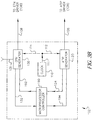
- a photoresist master disc 10 is shown in accordance with the present invention.
- the photoresist master disc 10 has a substrate 12 in which an inner peripheral edge 14 forms a central hole 16, and the disc 10 having an outer peripheral edge 18.
- the central hole 16 permits the photoresist master disc 10 to be mounted in a disc transport device of a laser beam recording system.
- the photoresist master disc 10 includes a read-only memory (ROM) area 30 and a recordable area 50.
- ROM read-only memory
- a photoresist layer 20 which is responsive to activating radiation of a laser beam in a laser beam recording system such that a laser beam incident on a surface 22 of the photoresist layer 20 will form a pattern of a spiral groove, and of depressions in the groove which correspond to recorded data in the ROM portion of the photoresist layer 20.
- the substrate 12 is usually formed of glass, but it can also be formed of quartz or of a ceramic material.
- the photoresist layer 20 is preferably formed by spin-coating of a positive-working photoresist material which is "activated” by exposure to activating radiation having a wavelength in a range from 350-450 nm.
- activated relates to a photochemical reaction upon exposure.
- both the ROM area 30 and the recordable area 50 are partitioned.
- the ROM area 30 is partitioned into a lead-in area, a program area, and a lead-out area.
- the recordable area likewise is partitioned to include a lead-in area, a program area, and at least one lead-out area.
- lead-in, program, and lead-out areas have been omitted from the drawing of FIG. 2.
- PCA power calibration area
- PMA program memory area
- Segments of a frequency-modulated groove 32 and 52 are schematically indicated in thin wavy outline.
- Segments of an intensity-modulated and frequency-modulated groove 34 are schematically depicted in the ROM area 30 in wavy outline interspersed with bold dots and dashes to indicate formation of depressions along such groove segments.
- FIG. 3A there is shown a block diagram of a first embodiment of a laser beam recording system for making a photoresist master disc from which a stamper can be fabricated for forming a hybrid optical recording disc.
- a laser 1 emits a laser beam 2 of activating radiation to which a photoresist layer 20 of a photoresist master disc 10 is responsive.
- the laser beam 2 is directed by a mirror 3 to a first optical modulator 180 which is dedicated to modulate the intensity of the laser beam 2 in response to signals provided by an EFM driver 138 via a lead 146.
- the intensity-modulated laser beam 4 depicted in bold, dashed, and dotted outline, is directed to a second optical modulator 160 dedicated to provide a frequency modulation to the intensity-modulated laser beam 4 in response to signals provided by an ATIP driver 128 via a lead 156.
- the frequency-modulated and intensity-modulated laser beam 5 is schematically indicated in a wavy outline with bold dots and dashes, and the laser beam 5 is focused by optical elements (not shown) to be incident on a surface 22 of a photoresist layer 20 at a point 6.
- the photoresist master disc 10 is rotated by a motor 60 via a disc-drive spindle 62 in a direction 63 of disc rotation during the recording process.
- the motor is operated under a motor rotational speed control 64, and the radial position of incidence of the laser beam 5 on the photoresist master disc 10 is determined by a radial position control 70 via a radial position linkage 72, so as to expose in the photoresist layer 20 a continuous spiral groove extending from the inner peripheral edge 14 to the outer peripheral edge 18 of the photoresist master disc 10, whereby the spiral groove is frequency-modulated (that is, wobbled) and is intensity-modulated to form depressions in the spiral groove in correspondence with recorded data.
- a laser beam modulation control system 100 has a central clock 110 which provides clock pulses via a leads 111 and 112 to an ATIP generator 120, and to an EFM generator 130 via a lead 114.
- ATIP is a commonly used abbreviation for "actual time in pregroove”
- EFM is a commonly used abbreviation for "Eight-to-Fourteen Modulation”.
- the ATIP generator and the EFM generator are also referred to as ATIP encoder and EFM encoder, respectively.
- the ATIP generator 120 is operative to provide control of the laser beam recording system in that the ATIP generator provides all of the timing functions in accordance with specifications contained in the aforementioned "Orange Book” or contained in the aforementioned “Red Book.”
- the ATIP generator 120 also provides a frequency-modulating signal via a lead 126 to the ATIP driver 128 which, in turn, drives the optical modulator 160 via the lead 156.
- This frequency-modulating signal also referred to as a wobble-frequency signal, comprises a carrier frequency of 22.5 kHz which is modulated with a frequency deviation of ⁇ 1kHz.
- the EFM generator 130 has an input lead 131 for receiving input signals from an external source (not shown) in a form of a digital data bit stream.
- the external data source can be, for example, a CD-ROM.
- the EFM generator 130 generates EFM signal pulses representative of 14-bit data streams and these pulses are directed to an EFM driver 138 via a lead 136, and from the EFM driver 138 via a lead 146 to the optical modulator 180 for modulating the intensity of the laser beam in correspondence with the data stream from the EFM generator 130.
- the laser beam modulation control system 100 further includes circuitry for controlling temporal relationships between and among the ATIP generator and the EFM generator so that respective ATIP signals and EFM signals are temporally correlated to provide concurrent operation of the first and second optical modulations 180 and 160.
- FIG. 3A depicts two logic circuits which link the ATIP generator 120 and the EFM generator 130.
- a first logic circuit 140 receives from the ATIP generator 120 via a lead 124 timing flag pulses which are sequenced in accordance with the timing function of the ATIP generator 120, and the logic circuit 140 conveys these timing flag pulses to an input of the EFM generator 130 via a lead 142.
- the ATIP generator 120 provides to the EFM generator 130 via the logic circuit 140 other pulsed signals, such as for example, SYNC pulse signals (synchronization pulse signals).
- a second logic circuit 150 provides a logic communication link between the EFM generator 130 and the ATIP generator 120 via leads 132 and 152, respectively.
- the logic signals communicated among the ATIP generator 120 and the EFM generator 130 provide so-called flag signals, or flags, which are hardware-based rather than requiring the decoding of software-based instructions.
- the hardware-based logic communication among the ATIP generator 120 and the EFM generator 130 proceeds in practice as follows: the EFM generator 130 first instructs the ATIP generator 120 via the logic circuit 150 about its readiness to produce intensity-modulating EFM signals corresponding to the input signals at lead 131. Upon receiving such instruction from the EFM generator 130, the ATIP generator 120 communicates timing signals to the EFM generator via the logic circuit 140 and, since the ATIP generator controls the timing sequence, that is when to switch from exposing a depression in the groove to exposing only the groove, and vice versa, in the photoresist layer 20, the ATIP generator 120 controls the EFM generator 130 as to when to change the laser beam intensity via the EFM driver 138 and the optical modulator 180.
- the logic circuits 140 and 150 are preferably TTL (transistor-to-transistor) logic circuits.
- These hardware-based logic flag signals (representing is and 0s) provide for microsecond response of the laser beam intensity modulation in the optical modulator 180.
- a laser beam modulation control system 102 is shown in which a microprocessor controller 190 performs the control of temporal relationships between and among signals from the ATIP generator 120 and the EFM generator 130 in a manner as described above.
- Corresponding leads are 124 and 192, and 132 and 194.
- FIG. 3C is a block diagram of a laser beam modulation control system 104 which includes a waveform modifier, a function generator, and a multiplexer.
- the laser beam modulation control system 104 has a central clock 110 which provides clock pulses via a leads 111 and 112 to an ATIP generator 120, and to an EFM generator 130 via a lead 114.
- the ATIP generator 120 provides a frequency-modulating signal via a lead 126 to the ATIP driver 128 which in turn, drives the optical modulator 160 via the lead 156 (see FIG. 3A).
- the EFM generator 130 has an input lead 131 for receiving input signals from an external source (not shown) in a form of a digital data bit stream.
- the external data source can be, for example, a CD-ROM.
- the EFM generator 130 generates EFM signal pulses representative of 14-bit data streams.
- An output of the EFM generator provides the EFM signal pulses to an input of a waveform modifier 230 via a lead 134.
- the waveform modifier 230 can introduce a selectable bias voltage level so that the EFM signal pulses are superimposed upon a selected bias voltage.
- the bias voltage is selected at a level sufficient to expose (in the absence of superimposed EFM signal pulses) a groove in the photoresist layer 20, for example, a groove 52 shown in the recordable area 50 of FIG. 2.
- the waveform modifier can be used to modify the shape of the EFM signal pulses provided by the EFM generator 130, if such pulse shape modification is advantageous.
- the ensuing description viewed in conjunction with the description of FIGS. 4A-4F, will be limited to the bias voltage aspect of the waveform modifier 230.
- An output of the waveform modifier 230 is connected to one signal input of a multiplexer 220 via a lead 232.
- the multiplexer is commonly abbreviated to the term "MUX".
- the MUX has a second signal input connected to an output of a function generator 210 via a lead 212.
- the function generator provides a temporally varying signal, for example, a ramp function signal, which is used advantageously in modulating the laser beam intensity so as to expose a groove pattern of varying depth in the photoresist layer 20, as will be described in greater detail hereinafter.
- the output of the mulitplexer 220 is connected to the input of the EMF driver 138 via a lead 226.
- the EMF driver 138 drives the optical modulator 180 via a lead 146 to modulate the intensity of the laser beam 2 (see FIG. 3A), thus providing the intensity-modulated laser beam 4 in correspondence with the output signals of the MUX.
- the laser beam modulation control system 104 further includes a controller 190 for controlling temporal relationships between and among signals from the ATIP generator 120 and the EFM generator 130 so that respective ATIP signals and EFM signals are temporally correlated to provide concurrent operation of the first and second optical modulations 180 and 160.
- the controller 190 is preferably a microprocessor which provides a control signal to the function generator 210 via a lead 198, and provides a control signal to a control signal input of the multiplexer 220 via a lead 196, in response to flag signals (digital 1s) communicated to and from the controller 190 between the ATIP generator 120 and EFM generator 130, and vice versa.
- the controller 190 receives from the ATIP generator 120 via a lead 124 timing flag pulses which are sequenced in accordance with the timing function of the ATIP generator 120, and the controller 190 conveys these timing flag pulses to an input of the EFM generator 130 via a lead 192.
- the ATIP generator 120 provides to the EFM generator 130 via the controller 190 other pulsed signals, such as for example, SYNC pulse signals (synchronization pulse signals).
- the controller 190 provides a second logic communication link between the EFM generator 130 and the ATIP generator 120 via leads 132 and 194, respectively.
- the logic signals communicated among the ATIP generator 120 and the EFM generator 130 via the controller 190 provide so-called flag signals, or flags, which are hardware-based rather than requiring the decoding of software-based instructions.
- the hardware-based logic communication among the ATIP generator 120 and the EFM generator occurs in a manner as described above with reference to FIGS. 3A and 3B.
- the photoresist layer Upon completion of the laser beam exposure of the photoresist layer, the photoresist layer is developed in a conventional manner, thereby producing the wobbled groove such as the wobbled groove segments 32 and 52 depicted in FIG. 2, and intensity-modulated wobbled groove segments (that is groove segments containing depressions) such as, for example, the intensity-modulated wobbled groove segment 34 shown in FIG. 2.
- a metal stamper is formed by plating against the patterned photoresist layer 20, and such stamper is then used to make hybrid optical recording disc substrates from a plastic material by embossing techniques or by injection molding techniques. In FIG. 10, a photographic rendition of a portion of such a metal stamper is shown.
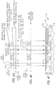
- FIGS. 4A-4C relationships are schematically indicated between laser beam intensity profiles for exposing a groove (G) and depressions (D) in the groove, respectively (FIG. 4A), and flag pulses representative of a digital data stream from the EFM generator 130 (FIG. 4B).
- FIG. 4C schematically indicates a portion of the photoresist master disc 10 showing laser beam generated exposure profiles in the photoresist layer 20 in correspondence with the intensity-modulated laser beam profile shown in FIG. 4A.
- a thickness t of the photoresist layer 20 is indicated.
- the photoresist layer thickness is in a preferred range of about 290-350 nm.
- FIGS. 5A-5F there are depicted schematically several signals associated with particular devices of the laser beam modulation control system 104 shown in FIG. 3C. All signals are drawn along a time axis which is also equivalent to a radial position at which the intensity-modulated and wobble-frequency-modulated laser beam 5 is incident at point 6 on the surface 22 of the photoresist layer 20 of the master disc 10 (see FIG. 3A). It will be appreciated that the signals represent only a few microseconds of recording time for exposing a groove (G) and depressions (D) in the groove (D + G).
- FIG. 5A shows a sequence of flag pulses as generated by the EFM generator 130 at lead 134 in correspondence with the digital data bit stream input at lead 131, and in accordance with the previously described logic communication between and among the ATIP generator 120 and the EFM generator 130 via the controller 190.
- These pulses, as well as all other signals shown in FIGS. 5B-5E, are depicted as positive-going signals, but it will be understood that some or all signals can be negative-going signals as may be required by operational characteristics of a particular device or of particular devices.
- the EFM generator output signal on lead 134 are flag pulses which rise from, and fall to, a zero voltage or signal level.
- the pulse height may be in a range from 3V to 24V typical of digital signaling systems.
- the above described EFM generator output signal has been modified by the waveform modifier 230 such that EFM generator output signal pulses are now superimposed on a bias level (a bias voltage).
- This waveform modifier output signal is directed to one input of the MUX 220 via lead 232 (see FIG. 3C).
- the bias voltage is selected so that the optical modulator 180 will modulate the laser beam 2 to produce a lower intensity laser beam 4 sufficient to expose a groove pattern to a selected depth into the photoresist layer 20 as measured from the surface 22 of the layer.
- the bias voltage may be selected in a range from about 0.1 to 24 volts.
- FIG. 5C shows schematically a ramp function signal generated by the function generator 210 in response to an input signal from the controller 190 via lead 198.
- the function generator output signal is directed to a second input of the MUX 220 via a lead 212.
- the function generator output signal is shown here as a ramp function which increases linearly with time from an initial level above a zero level to a maximum ramp signal V R .
- the ramp signal is shown to decrease from V R to zero at a time slightly longer than a time of a last EFM generator output signal pulse, as indicated by dotted reference lines.
- the function generator 210 is capable of generating other output signals, such as, for example, a signal increasing non-linearly with time, or a signal which first increases over a first time period, followed by a decrease over a subsequent second time period. It will also be appreciated that the controller 190, which controls the starting time and the termination time of the output signal of the function generator 210, can direct the function generator to provide an output signal for a substantially shorter time period than depicted in FIG. 5C.
- An important aspect of the function generator 210 is to provide an output signal to the second input of the MUX 220 of a signal level selected to determine, for example, in a power calibration area (PCA) of the photoresist master disc (see FIG. 2), a level of intensity modulation of the laser beam via the optical modulator 180 which is sufficient to expose a discernible and developable groove in the photoresist layer 20 for the various regions shown in FIG. 4A.
- PCA power calibration area
- FIG. 5D depicts a MUX control signal provided by the controller 190 to a control signal input of the multiplexer 220 via a lead 196.
- the MUX 220 is an electronic switch which directs either the waveform modifier output signal (see FIG. 5B) or the function generator output signal (see FIG. 5C) to the EFM driver 138 via the lead 226 in response to the MUX control signal.
- a MUX output signal on lead 226 is a composite signal of the waveform modifier output signal whenever the MUX control signal is in an "on-state", and of the function generator output signal whenever the MUX control signal is in an "off-state", that is at a zero level.
- the optical modulator 180 will provide an intensity-modulated laser beam 4 in correspondence with the MUX output signal via the EFM driver 138.
- FIG. 5F schematically indicates exposed depressions D in segments of the exposed spiral groove G, in correspondence with a laser beam exposure which was intensity-modulated by the composite MUX output signal of FIG. 5E.
- the data track(s) 34 in the spiral groove segments 32 are exposed at a higher intensity in correspondence with the higher pulsed portions of the MUX output signal.
- the recordable area or portion 50 of the spiral wobbled groove 52 has a constant depth exposure as measured from the upper surface 22 of the photoresist layer 20.
- FIG. 6A there is depicted schematically a segment of a wobbled groove 32 (see FIG. 2) exposed in the photoresist layer 20.
- the wobbled groove is also intensity-modulated in the form of exposed depressions (D) which correspond to recorded data, and depressions corresponding to SYNC signals. Regions of the groove 32 which are devoid of exposed depressions are indicated at G. Together, the exposed depressions (D) can be visualized as a track of depressions 34 in the exposed wobbled groove 32.
- FIG. 6B depicts schematically laser beam intensity-modulating pulses provided to the EFM driver 138 by the modulation control systems 100, 102 or 104 (see FIGS. 3A-3C).
- the function generator output signal (see FIGS. 5C, 5E) has been omitted from this drawing.
- the ATIP generator 120 provides via the clock 110 SYNC pulses through the controller 190 to the EFM generator 130 which, in turn, results in the exposure of SYNC depressions in the groove 34 via the optical modulator 180.
- FIG. 6C schematically indicates the wobble-frequency signal provided by the ATIP generator 120 to the optical modulator 160 via the ATIP driver 128.
- the peak-to-peak wobble of a wobbled groove is typically a range of about 30 nm.
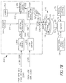
- FIG. 7A is a schematic block diagram of a dual-beam laser recording system 300 suitable for exposing a wobbled groove, and depressions in the groove in the ROM area, in a photoresist layer 20 of a master disc 10.
- the laser beam modulation control system 100 previously described with reference to FIG. 3A is shown here for illustrative purposes. It will be understood that the laser beam modulation control systems 102 or 104 described with reference to FIGS. 3B and 3C, respectively, can be used to control the recording system 300.
- a laser 310 emits a laser beam 311 of activating radiation to which the photoresist layer 20 is responsive.
- a beam splitter 314 splits the laser beam 311 into two laser beams 315, 317.
- the first laser beam 315 is intensity-modulated by an optical modulator 322 which is activated or driven by an EFM driver 360 via a lead 362.
- the optical modulator 322, the EFM driver 360, and the lead 362 correspond to the modulator 180, the driver 138, and the lead 146, respectively, of the laser beam recording system of FIG. 3A.
- the optical modulator 322 produces an intensity-modulated laser beam 325 depicted in dashed and dotted outline.
- the second laser beam 317 is directed by a mirror 316 to an optical modulator 326 which provides a frequency-modulated laser beam 327, indicated in wavy outline.
- An intensity controller 330 provides an intensity-controlling bias signal to the modulator 326 via a lead 332 for selecting a laser beam intensity level of the wobble-frequency-modulated ("wobbled") laser beam 327, as will be described in greater detail with reference to FIGS. 8A-8C and 9A, 9B.
- the laser beam 327 is directed via a mirror 336 to a beam combiner 334 which recombines the first intensity-modulated laser beam 325 and the second wobble-frequency-modulated laser beam 327. If perfect optical alignment can be achieved, the beam combiner 334 would provide two spatially superimposed laser beams 335 (intensity-modulated) and 335 (frequency-modulated) which would expose the photoresist layer 20 at a single point of incidence thereon. However, in order to more clearly illustrate the distinguishing recording aspects of the dual-beam laser recording system 300 compared with the recording aspects of the system of FIG.
- the laser beams 335 and 337 are depicted with a small lateral spacing s therebetween which extends to the points of incidence 345 and 347, respectively, of these laser beams on the photoresist layer 20.
- the spacing s is a radial spacing, that is a spacing which produces an exposed wobbled groove in the photoresist layer 20 and a track of exposed depressions spaced from a centerline of the exposed groove
- the radial spacing s has to be confined within certain limits as will be further detailed with respect to FIGS. 8C and 9B.
- spacing s between the points of incidence 245 and 247 of the laser beams 335 and 337, respectively, occurs along one and the same radial position of the rotating and radially translating photoresist master disc 10, such spacing can be confined to a lesser extent.
- the photoresist master disc 10, the speed control 64, and the radial position control 70 have been described with reference to FIG. 3A and require, therefore, no additional description.
- FIG. 7B is a schematic block diagram of another embodiment of a dual-beam laser recording system 302 which differs from the above described dual-beam system 300 in that two separate lasers 310 and 312 are used to provide corresponding first and second laser beams 311 and 313, respectively.
- the first laser beam 311 is intensity-modulated by the modulator 322, and the second laser beam 313 received a wobble-frequency modulation in the optical modulator 326, as described with reference to FIG. 7A.
- All other parts, aspects, and functions of the dual-beam laser recording system 302 correspond to like parts, aspects, and functions of the system 300 of FIG. 7A.
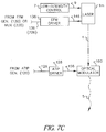
- FIG. 7C is a schematic block diagram of an alternative laser beam recording system in which a single modified laser 1m provides an intensity-modulated laser beam 4 (intensity-modulated between a lower intensity level and a higher intensity level) which is concurrently modulated with a wobble-frequency in an optical modulator 160 to provide an intensity- and frequency-modulated laser beam 5 for exposing a photoresist layer of a master disc (not shown in FIG. 7C; see FIG. 3A).
- a single modified laser 1m provides an intensity-modulated laser beam 4 (intensity-modulated between a lower intensity level and a higher intensity level) which is concurrently modulated with a wobble-frequency in an optical modulator 160 to provide an intensity- and frequency-modulated laser beam 5 for exposing a photoresist layer of a master disc (not shown in FIG. 7C; see FIG. 3A).
- the laser 1m is operative via a low-intensity control 7 provided at a lead 9 to provide a lower-intensity level (also referred to as a "bias" intensity level) in the absence of flag pulses from the EFM generator 130 via lead 136 (see FIGS. 3A, 3B) or in the absence of signals from the multiplexer 220 via lead 226 (see FIG. 3C).
- a lower-intensity level also referred to as a "bias" intensity level
- the EFM driver 138 actuates the laser 1m directly via lead 146 to provide a higher-intensity level in response to such flag pulses so that the intensity-modulated laser beam 4 emanates therefrom.
- FIGS. 8A-8C and 9A-9B refer particularly to exposure of the photoresist layer 20 by one of the dual-beam laser recording systems 300 or 302 which were depicted to have the small spacing s between the two modulated laser beams 335 and 337 at their corresponding points of incidence 345 and 347, respectively, on the surface 22 of the photoresist layer 20.
- FIGS. 8A-8C and 9A-9B together will more readily inform as to the distinguishing features of such exposures over exposures of a photoresist master disc provided by a single-beam laser recording system such as, for example, the system of FIG. 3A or of FIG. 7C.
- FIGS. 8A and 9A show schematically a frequency-modulating drive signal having a signal amplitude as measured at lead 372, that is the lead which connects an output of the ATIP driver 370 to an input of the optical modulator 326 of FIGS. 7A and 7B.
- the intensity control 330 provides to the optical modulator 326 a bias level signal at lead 332 which results in a steady laser light beam intensity at a level 1 (also referred to as a level 1 bias light level).
- a level 1 also referred to as a level 1 bias light level
- the intensity control 330 provides to the optical modulator 326 a bias level signal which results in a steady laser light beam intensity at a level 2 which is depicted, for illustrative purposes, to be higher than the level 1 intensity being transmitted as the frequency-modulated laser beam 327 by the modulator 326.
- intensity-modulating drive signals (flag pulses and SYNC pulses) are shown as measured at lead 362 which connects an output of the EFM driver 360 with an input of the optical modulator 322 for exposing depressions in the photoresist layer 20 in correspondence with data (0's or 1's).
- flag pulses do not require a low-intensity bias level, in contrast to the single-beam recording systems as described with particular reference to FIGS. 4A, 5B-5E, and 6B, since the wobbled groove G is continuously exposed in the photoresist layer 20 by the frequency-modulated second laser beam 337 in the dual-beam recording systems 300, 302.
- the wobbled groove G is exposed by the second laser beam 337, and a track of depressions D is exposed by the first laser beam 345 in correspondence with the digital data bit stream input to the EFM generator 130.
- a substantially identical sequence of flag pulses and SYNC pulses has been omitted in FIGS. 9A and 9B.
- a center line 33 of an exposed wobbled groove 32 is radially spaced by a spacing s from a center line 35 of a track 34 of exposed depressions which are exposed in the photoresist layer 20 in accordance with the flag pulses as indicated by the dotted reference lines extending between FIGS. 8B and 8C.
- the exposed wobbled groove 32 of FIG. 8C has an exposed width dimension W1 which corresponds to the laser light beam intensity level 1 of the frequency-modulating drive signal (see FIG. 8A) and provided to the optical modulator 326 by the intensity control 330 via lead 332.
- the exposed wobbled groove 32 of FIG. 9B is depicted with an exposed width dimension W2 which corresponds to the laser light beam intensity level 2 of the frequency-modulating drive signal (see FIG. 9A).
- the spacing s between the first and second laser beams 335 and 337 is a radial spacing between the points of incidence 345 and 347 on the surface 22 of the photoresist layer 20 (see FIGS. 7A and 7B), as schematically shown in FIGS. 8C and 9B, the radial spacing must be limited so that a diameter ⁇ R of a reading laser light beam can read a wobbled groove G and the depressions D through the substrate of a finished hybrid optical recording disc.
- the track 34 of exposed depressions D would remain a straight-line track which is now centered within an exposed wobbled groove G of an exposed width dimension W1 or W2.
- a substantially identical result is obtained if the first and second laser beams 335 and 337 have a spacing s which extends along one and the same radial position of the rotating photoresist master disc 10.
- FIG. 10 there is shown a photographic reproduction of a small portion of a metal stamper which was formed by plating a laser beam-exposed and subsequently developed photoresist master disc 10.
- the photograph of the stamper is taken in a PMA area (see FIG. 2) and shows transitions between segments which will form a wobbled groove, to segments which will form a wobbled groove having deep depressions, and finally to segments which will form a wobbled groove, in a molded hybrid optical disc substrate.
- photoresist will be understood to include conventional photoresists which are light sensitive, but also other materials which are radiation sensitive and can be used, for example, in electron beam recording systems.
- the laser beam recording system wherein the at least one laser provides the first and second laser beams by means for splitting a laser beam from the at least one laser into the first and second laser beams.
- the laser beam recording system wherein the first and second laser beams are provided by a first and a second laser, respectively.
- the laser beam recording system wherein the first and second laser beams have a wavelength in a range from 350 to 450 nm, the photoresist layer is formed of a positive-working photoresist material, and the photoresist layer has a thickness in a range from 290 to 350 nm.
- the laser beam recording system wherein the laser beam modulation control system includes at least logic means for temporally correlating drive signals provided to the first and second optical modulators.
- the laser beam recording system wherein the logic means further includes synchronization (SYNC) pulses which periodically synchronize a temporal relationship between the exposed wobbled groove and the track of exposed depressions.
- SYNC synchronization
- the laser beam recording system wherein at least some of the exposed depressions within a track of exposed depressions are exposed at positions spaced from a center line of the exposed wobbled groove.
- the laser beam recording system further including means for rotating the photoresist master disc during exposure of the photoresist layer to the at least one laser beam, and means for radially translating the master disc so that the at least one laser beam incident on the photoresist layer will trace a continuous exposed spiral groove.
- the laser beam recording system further including means for rotating the photoresist master disc during exposure of the photoresist layer to the first and second laser beams, and means for radially translating the master disc so that the wobbled groove will trace a continuous exposed spiral groove.
- the laser beam recording system wherein the means for frequency-modulating the intensity-modulated laser beam includes an optical modulator.
- the laser beam recording system wherein the means for controlling temporal relationships include a first logic circuit for creating flag pulses directed from the EFM generator to the ATIP generator, or vice versa, and a second logic circuit for creating flag pulses directed from the ATIP generator to the EFM generator, or vice versa.
- the laser beam recording system wherein the first and the second logic circuits include TTL logic circuits.
- the laser beam recording system wherein the means for controlling temporal relationships include a microprocesor controller.
- the laser beam recording system wherein the EFM generator provides signals to an EFM driver which, in turn, actuates the means for modulating the intensity of the laser beam.
- the laser beam recording system wherein the ATIP generator provides signals to an ATIP driver which, in turn, actuates the optical modulator for frequency-modulating the laser beam.
- the laser beam recording system wherein the EFM generator provides a lower level signal to the EFM driver so that a lower intensity laser beam is provided for exposing the groove in the photoresist layer, and the EFM generator provides a higher level signal to the EFM driver in correspondence with the digital data input signals so that a higher intensity laser beam is provided for exposing the groove and the pattern of depressions in the groove in the photoresist layer.
- the laser beam recording system wherein the ATIP generator and the EFM generator further provide synchronization (SYNC) pulses which periodically synchronize a temporal relationship between the intensity modulation and the frequency modulation along the exposed spiral groove.
- SYNC synchronization
- the laser beam recording system wherein the means for controlling the temporal relationships is operative to control via flag pulses the timing of release of digital data input signals and the timing and the lower and higher intensity of the laser beam provided by the first optical modulator so that the photoresist layer upon development will have a continuous frequency-modulated spiral groove and depressions within portions of the groove corresponding to data in a ROM area of the master disc.
- the laser beam recording system wherein the laser beam has a wavelength in a range from 350 to 450 nm, the photoresist layer is formed of a positive-working photoresist material, and the photoresist layer has a thickness in a range from 290-350 nm.
- the laser beam recording system wherein the ATIP generator and the EFM generator further provide synchronization (SYNC) pulses which periodically synchronize a temporal relationship between the intensity modulation and the frequency modulation along the exposed spiral groove.
- SYNC synchronization
- the laser beam recording system wherein the laser beam has a wavelength in a range from 350 to 450 nm, the photoresist layer is formed of a positive-working photoresist material, and the photoresist layer has a thickness in a range from 290-350 nm.
- the laser beam recording system wherein the time-varying signal generated by the function generator is a ramp signal.
- the laser beam recording system wherein the ramp signal increases linearly with time.
- the laser beam recording system wherein the ramp signal increases non-linearly with time.
Abstract
Description
- The present invention relates to optical recording discs and more particularly to a system for making a photoresist master disc from which a stamper can be made for forming a hybrid optical recording disc.
- Hybrid optical recording discs are discs having a read-only memory (ROM) area and a recordable area for recording or writing data which are usually generated by a computer user and which are recorded on the disc by a recorder or writer controlled by a computer. Such a disc has a substrate which can be formed by injection molding against a master plate so that the mastered substrate will have a continuous spiral track extending from an inner edge to an outer edge of the substrate. The spiral tack is usually a groove which provides data channels on the disc and also provides for tracking of the disc while reading or recording data. The groove is frequency-modulated in a direction normal to the groove and is, therefore, referred to as a wobbled groove or a wobble groove. In the ROM area of a hybrid optical disc the groove is further modulated in the form of depressions which correspond to disc addressing data and to disc program data. The mastered substrate is then coated with a recording layer which can include an organic dye selected to absorb radiation in the recordable area. Upon coating the recording layer, a reflective layer is formed over the entire recording layer. A protective layer, usually of a polymer organic material, is formed over the reflective layer.
- The tracks or grooves of a hybrid optical recording disc, the degree of modulation of the groove, as well as the arrangement of addressing and program data is usually provided in accordance with Orange Book specifications. "Orange Book" is a specification published by Philips Corporation and Sony Corporation which defines key properties of recordable compact disc media and recording performance.
- The aforementioned master plate is used to produce numerous plastic disc substrates by embossing or injection molding techniques. Such a master plate is also referred to as a stamper. The stamper, in turn, is produced by metal plating techniques whereby a photoresist master having the spiral groove and the data depressions is plated with a metal. The metal layer is then separated from the photoresist master and constitutes the stamper which replicates the features of the photoresist master in an inverted orientation, that is a groove in the photoresist master will be a projection in the stamper. The photoresist master disc comprises a photoresist layer formed over a substrate which is usually a glass substrate. Accordingly, the photoresist master is also referred to in the art as a glass master.
- Depending on the configuration and on the intended application of an optical disc, particular challenges and problems need to be addressed to meet and to retain specifications in accordance with standards such as, for example, defined in the aforementioned Orange Book or in a Red Book, also published by Philips Corporation and Sony Corporation. For example, US-A-5,862,123 disclose optical phase-change material formed on a substrate which has a wobbled spiral groove on a substrate. Particular relationships are selected between a groove width, a laser beam diameter, and a wobble amplitude to prevent distortion of the groove caused by repeated over-writing operations. In FIG. 10 of US-A-5,862,123, a block diagram of a laser beam recording apparatus is shown for recording grooves and data on a photoresist layer formed over a glass substrate, that is for recording a "glass master" having the selected particular relationships.
- Udagawa, US-A-5,737,289 discloses a data recording apparatus providing different plural recording laser powers within respective subcode frames constituting sub-partitions of an optical disc so as to determine an optimum laser drive power. Also disclosed are laser drive circuit and control circuitry.
- US-A-5,297,129 disclose a method and apparatus for shaping the waveform of laser pulses to achieve improved characteristics (leading and trailing edges) of surface effects recorded on an optical disc. An optical modulator is used to modulate the intensity of a laser beam either above or below a threshold level to either produce surface effects on a moving recording medium, or to be incapable of producing surface effects on the moving recording medium when the laser beam intensity is below a threshold level.
- The fabrication of a photoresist master disc dedicated to forming a hybrid optical recording disc poses significant technological challenges which differ from the challenges encountered by the above cited references. Firstly, conventional laser beam recording systems for recording a photoresist master dedicated for a conventional CD-ROM do not have the ability to record a photoresist master in a multi-session format required of a hybrid optical recording disc. Nor do such conventional CD-ROM laser beam recording systems provide a capability to record frequency-modulated or wobbled grooves. For example, in a hybrid optical disc, the ROM area includes a first session which includes a ROM lead-in area, a ROM program area, and a ROM lead-out area. The recordable area of the hybrid optical disc constitutes a second session comprising a lead-in area, a recordable program area, and a lead-out area. Since the hybrid optical recording disc has a recordable area, the photoresist master for such a disc must be recorded so as to simulate a CD writer and thus write the first session and leaving it open for appending, that is for subsequent writing in the recordable area of the hybrid optical disc, the writing to be performed by a computer user. It is also required to record in such a photoresist master various codes and addressing data which allow a writer to recognize the hybrid optical disc as being writable.
- Furthermore, a photoresist master for a hybrid optical disc must meet particular specifications within a transition area between the lead-out area of a recorded first session and a lead-in area of the recordable second session.
- In particular, the transition between the ROM area and the recordable area has a specification of a 26EFM frame interval. An EFM generator is used to modulate the intensity of a laser beam so as to record a continuous spiral groove and data in portions of the groove in the form of depressions. A frame has a typical duration of about 130 microseconds. Conventional laser beam recording systems designed for recording photoresist masters for conventional CD-ROMs rely on decoding a subcode in the EFM data stream to change or to modulate the recording laser beam via a coded channel such as a RS232 channel. However, the response of a typical RS232 channel is in a range of milliseconds, a response time which is too long for meeting the 26EFM frame interval requirement accurately and consistently.
- Thus, existing conventional laser beam recording systems for recording photoresist masters of conventional CD-ROMs have to be modified in order to have a performance which meets the requirements of recording a photoresist master for a multi-session hybrid optical recording disc.
- It is an object of the present invention to provide a laser beam recording system for making a photoresist master for a hybrid optical recording disc.
- This and other objects and advantages are achieved in a radiation beam recording system for exposing a photoresist master disc having a photoresist layer formed over a substrate for making a hybrid optical recording disc having a read only (ROM) portion and a writable portion, comprising:
- a) at least one radiation source which provides first and second radiation beams projected along first and second beam paths, respectively, each beam having a wavelength or energy selected to provide activating radiation for exposing a pattern in the photoresist layer formed over the substrate of the master disc;
- b) a first modulator for modulating an intensity of the first radiation beam and disposed along the first beam path, such intensity modulation having an intensity for exposing depressions in the photoresist layer in correspondence with data to be recorded;
- c) a second modulator for frequency-modulating the second radiation beam and disposed along the second beam path, such frequency modulation providing a wobble-frequency to cause an exposed groove in the photoresist layer to be a continuous wobbled groove;
- d) means for combining the modulated first and second radiation beams and for projecting the combined radiation beams onto the photoresist layer for exposing the photoresist layer to form the exposed continuous wobbled groove and a track of exposed depressions along the wobbled groove; and
- e) a modulation control system for controlling the operation of the first and the second modulator to concurrently form the exposed continuous wobbled groove and the track of exposed depressions along the wobbled groove in the ROM portion.
-
- In another aspect of the present invention logic flag signals are provided between and among an ATIP generator and an EFM generator to achieve microsecond response times in modulating the intensity of a laser beam. The logic flag signals are used between the ATIP generator and the EFM generator, or vice versa, to modulate the intensity of a laser beam to achieve desirable geometric features of the recorded groove and the depressions in a transition region between a ROM area and a recordable area of a hybrid disc. The term ATIP refers to "absolute time in pregroove". The term EFM refers to "eight-to-fourteen modulation".
- FIG. 1 is a simplified schematic perspective view of a photoresist master disc having a ROM area and a recordable area;
- FIG. 2 is a schematic plan view of the photoresist master disc of FIG. 1, indicating frequency-modulated segments of a groove and intensity-modulated and frequency-modulated segments of a groove as well as a power calibration area (PCA) and a program memory area (PMA);
- FIG. 3A is a block diagram of a first embodiment of a laser beam recording system in accordance with the present invention for recording concurrently a frequency-modulated and intensity-modulated groove on a photoresist master disc;
- FIG. 3B shows an alternative means for controlling temporal relationships between intensity-modulating signals and frequently-modulating signals;
- FIG. 3C shows an alternative means for controlling temporal relationships between intensity-modulating signals and frequency-modulating signals, and including a waveform modifier, a function generator, and a multiplexer;
- FIGS. 4A-4C show schematically relationships between flag pulses, a laser beam intensity profile for exposing a groove (G) and for exposing depressions (D) in a groove in a ROM area of the master disc, and an exposure profile in a photoresist layer of a master disc;
- FIGS. 5A-5F depict schematically several signals associated with particular devices of the laser beam modulation control system of FIG. 3C and an exposure prefile in a photoresist layer of a master disc exposed by a laser beam controlled by such signals;
- FIGS. 6A-6C show schematically a segment of a frequency-modulated wobble groove (G) containing the depressions (D), a laser beam intensity profile, and a laser beam wobble signal, respectively;
- FIG. 7A is a schematic block diagram of a dual-beam laser recording system in accordance with the present invention in which a laser beam is split into first and second beams for providing an intensity-modulated laser beam and a frequency-modulated laser beam for recording on a photoresist master disc;
- FIG. 7B is a schematic block diagram of a dual-beam laser recording system in accordance with the present invention in which first and second laser beams are provided by separate lasers for generating an intensity-modulated laser beam and a frequency-modulated laser beam for recording on a photoresist master disc;
- FIG. 7C is a schematic block diagram of an alternative laser beam recording system in which a single laser provides an intensity-modulated laser beam by directly intensity-modulating the laser;
- FIGS. 8A-8C show schematically relationships between a frequency-modulating drive signal biased at a first intensity level and intensity-modulating flag pulses to expose a wobbled groove and a track of depressions extending along the wobbled groove in the photoresist layer of the master disc;.
- FIGS. 9A-9B show schematically a relationship between a frequency-modulating drive signal biased at a higher second intensity level to expose a wider wobbled groove and the track of depressions of FIG. 8C; and
- FIG. 10 is a representation of a photographic rendition of a portion of the surface of a stamper made from a photoresist master and showing transitions from segments of a groove, to depressions along a groove, to groove segments in a PMA area of the photoresist master disc.
-
- It will be appreciated that the drawings are necessarily of a schematic nature since the temporal relationships of pulses and signals are controlled within a range of a fraction of a microsecond. Additionally, the depth dimensions of the photoresist layer and the depressions exposed therein, as well as the lateral dimensions of the wobbled groove and of the depressions in the ROM area of the groove, are too small to permit appropriate or proportionate scaling.
- Referring to FIG. 1 and FIG. 2, a
photoresist master disc 10 is shown in accordance with the present invention. Thephotoresist master disc 10 has asubstrate 12 in which an innerperipheral edge 14 forms acentral hole 16, and thedisc 10 having an outerperipheral edge 18. Thecentral hole 16 permits thephotoresist master disc 10 to be mounted in a disc transport device of a laser beam recording system. Thephotoresist master disc 10 includes a read-only memory (ROM)area 30 and arecordable area 50. Overlying thesubstrate 12 is aphotoresist layer 20 which is responsive to activating radiation of a laser beam in a laser beam recording system such that a laser beam incident on asurface 22 of thephotoresist layer 20 will form a pattern of a spiral groove, and of depressions in the groove which correspond to recorded data in the ROM portion of thephotoresist layer 20. - The
substrate 12 is usually formed of glass, but it can also be formed of quartz or of a ceramic material. Thephotoresist layer 20 is preferably formed by spin-coating of a positive-working photoresist material which is "activated" by exposure to activating radiation having a wavelength in a range from 350-450 nm. The term "activated" relates to a photochemical reaction upon exposure. - In accordance with the specification of the "Orange Book", both the
ROM area 30 and therecordable area 50 are partitioned. For example, theROM area 30 is partitioned into a lead-in area, a program area, and a lead-out area. The recordable area likewise is partitioned to include a lead-in area, a program area, and at least one lead-out area. For purposes of clarity of presentation, such lead-in, program, and lead-out areas have been omitted from the drawing of FIG. 2. - Near the inner
peripheral edge 14, a power calibration area (PCA) and a program memory area (PMA) are shown. - Segments of a frequency-modulated
groove groove 34 are schematically depicted in theROM area 30 in wavy outline interspersed with bold dots and dashes to indicate formation of depressions along such groove segments. - Turning to FIG. 3A, there is shown a block diagram of a first embodiment of a laser beam recording system for making a photoresist master disc from which a stamper can be fabricated for forming a hybrid optical recording disc. A
laser 1 emits alaser beam 2 of activating radiation to which aphotoresist layer 20 of aphotoresist master disc 10 is responsive. Thelaser beam 2 is directed by a mirror 3 to a firstoptical modulator 180 which is dedicated to modulate the intensity of thelaser beam 2 in response to signals provided by anEFM driver 138 via alead 146. The intensity-modulatedlaser beam 4, depicted in bold, dashed, and dotted outline, is directed to a secondoptical modulator 160 dedicated to provide a frequency modulation to the intensity-modulatedlaser beam 4 in response to signals provided by anATIP driver 128 via alead 156. The frequency-modulated and intensity-modulatedlaser beam 5 is schematically indicated in a wavy outline with bold dots and dashes, and thelaser beam 5 is focused by optical elements (not shown) to be incident on asurface 22 of aphotoresist layer 20 at apoint 6. - The
photoresist master disc 10 is rotated by amotor 60 via a disc-drive spindle 62 in adirection 63 of disc rotation during the recording process. The motor is operated under a motorrotational speed control 64, and the radial position of incidence of thelaser beam 5 on thephotoresist master disc 10 is determined by aradial position control 70 via aradial position linkage 72, so as to expose in the photoresist layer 20 a continuous spiral groove extending from the innerperipheral edge 14 to the outerperipheral edge 18 of thephotoresist master disc 10, whereby the spiral groove is frequency-modulated (that is, wobbled) and is intensity-modulated to form depressions in the spiral groove in correspondence with recorded data. - A laser beam
modulation control system 100 has acentral clock 110 which provides clock pulses via a leads 111 and 112 to anATIP generator 120, and to anEFM generator 130 via alead 114. "ATIP" is a commonly used abbreviation for "actual time in pregroove" and "EFM" is a commonly used abbreviation for "Eight-to-Fourteen Modulation". The ATIP generator and the EFM generator are also referred to as ATIP encoder and EFM encoder, respectively. TheATIP generator 120 is operative to provide control of the laser beam recording system in that the ATIP generator provides all of the timing functions in accordance with specifications contained in the aforementioned "Orange Book" or contained in the aforementioned "Red Book." TheATIP generator 120 also provides a frequency-modulating signal via alead 126 to theATIP driver 128 which, in turn, drives theoptical modulator 160 via thelead 156. This frequency-modulating signal, also referred to as a wobble-frequency signal, comprises a carrier frequency of 22.5 kHz which is modulated with a frequency deviation of ± 1kHz. - The
EFM generator 130 has aninput lead 131 for receiving input signals from an external source (not shown) in a form of a digital data bit stream. The external data source can be, for example, a CD-ROM. TheEFM generator 130 generates EFM signal pulses representative of 14-bit data streams and these pulses are directed to anEFM driver 138 via alead 136, and from theEFM driver 138 via alead 146 to theoptical modulator 180 for modulating the intensity of the laser beam in correspondence with the data stream from theEFM generator 130. - The laser beam
modulation control system 100 further includes circuitry for controlling temporal relationships between and among the ATIP generator and the EFM generator so that respective ATIP signals and EFM signals are temporally correlated to provide concurrent operation of the first and secondoptical modulations ATIP generator 120 and theEFM generator 130. Afirst logic circuit 140 receives from theATIP generator 120 via alead 124 timing flag pulses which are sequenced in accordance with the timing function of theATIP generator 120, and thelogic circuit 140 conveys these timing flag pulses to an input of theEFM generator 130 via alead 142. In addition, theATIP generator 120 provides to theEFM generator 130 via thelogic circuit 140 other pulsed signals, such as for example, SYNC pulse signals (synchronization pulse signals). - A
second logic circuit 150 provides a logic communication link between theEFM generator 130 and theATIP generator 120 vialeads - The logic signals communicated among the
ATIP generator 120 and theEFM generator 130 provide so-called flag signals, or flags, which are hardware-based rather than requiring the decoding of software-based instructions. - The hardware-based logic communication among the
ATIP generator 120 and theEFM generator 130 proceeds in practice as follows: theEFM generator 130 first instructs theATIP generator 120 via thelogic circuit 150 about its readiness to produce intensity-modulating EFM signals corresponding to the input signals atlead 131. Upon receiving such instruction from theEFM generator 130, theATIP generator 120 communicates timing signals to the EFM generator via thelogic circuit 140 and, since the ATIP generator controls the timing sequence, that is when to switch from exposing a depression in the groove to exposing only the groove, and vice versa, in thephotoresist layer 20, theATIP generator 120 controls theEFM generator 130 as to when to change the laser beam intensity via theEFM driver 138 and theoptical modulator 180. Thelogic circuits - These hardware-based logic flag signals (representing is and 0s) provide for microsecond response of the laser beam intensity modulation in the
optical modulator 180. - In FIG. 3B, a laser beam
modulation control system 102 is shown in which amicroprocessor controller 190 performs the control of temporal relationships between and among signals from theATIP generator 120 and theEFM generator 130 in a manner as described above. Corresponding leads are 124 and 192, and 132 and 194. - FIG. 3C is a block diagram of a laser beam
modulation control system 104 which includes a waveform modifier, a function generator, and a multiplexer. - The laser beam
modulation control system 104 has acentral clock 110 which provides clock pulses via a leads 111 and 112 to anATIP generator 120, and to anEFM generator 130 via alead 114. - The
ATIP generator 120 provides a frequency-modulating signal via alead 126 to theATIP driver 128 which in turn, drives theoptical modulator 160 via the lead 156 (see FIG. 3A). - The
EFM generator 130 has aninput lead 131 for receiving input signals from an external source (not shown) in a form of a digital data bit stream. The external data source can be, for example, a CD-ROM. TheEFM generator 130 generates EFM signal pulses representative of 14-bit data streams. An output of the EFM generator provides the EFM signal pulses to an input of awaveform modifier 230 via alead 134. Thewaveform modifier 230 can introduce a selectable bias voltage level so that the EFM signal pulses are superimposed upon a selected bias voltage. The bias voltage is selected at a level sufficient to expose (in the absence of superimposed EFM signal pulses) a groove in thephotoresist layer 20, for example, agroove 52 shown in therecordable area 50 of FIG. 2. Additionally, the waveform modifier can be used to modify the shape of the EFM signal pulses provided by theEFM generator 130, if such pulse shape modification is advantageous. For purposes of clarity of presentation, the ensuing description, viewed in conjunction with the description of FIGS. 4A-4F, will be limited to the bias voltage aspect of thewaveform modifier 230. - An output of the
waveform modifier 230 is connected to one signal input of amultiplexer 220 via alead 232. The multiplexer is commonly abbreviated to the term "MUX". The MUX has a second signal input connected to an output of afunction generator 210 via alead 212. The function generator provides a temporally varying signal, for example, a ramp function signal, which is used advantageously in modulating the laser beam intensity so as to expose a groove pattern of varying depth in thephotoresist layer 20, as will be described in greater detail hereinafter. - The output of the
mulitplexer 220 is connected to the input of theEMF driver 138 via alead 226. TheEMF driver 138, in turn, drives theoptical modulator 180 via alead 146 to modulate the intensity of the laser beam 2 (see FIG. 3A), thus providing the intensity-modulatedlaser beam 4 in correspondence with the output signals of the MUX. - The laser beam
modulation control system 104 further includes acontroller 190 for controlling temporal relationships between and among signals from theATIP generator 120 and theEFM generator 130 so that respective ATIP signals and EFM signals are temporally correlated to provide concurrent operation of the first and secondoptical modulations controller 190 is preferably a microprocessor which provides a control signal to thefunction generator 210 via alead 198, and provides a control signal to a control signal input of themultiplexer 220 via alead 196, in response to flag signals (digital 1s) communicated to and from thecontroller 190 between theATIP generator 120 andEFM generator 130, and vice versa. Thecontroller 190 receives from theATIP generator 120 via alead 124 timing flag pulses which are sequenced in accordance with the timing function of theATIP generator 120, and thecontroller 190 conveys these timing flag pulses to an input of theEFM generator 130 via alead 192. In addition, theATIP generator 120 provides to theEFM generator 130 via thecontroller 190 other pulsed signals, such as for example, SYNC pulse signals (synchronization pulse signals). - The
controller 190 provides a second logic communication link between theEFM generator 130 and theATIP generator 120 vialeads - The logic signals communicated among the
ATIP generator 120 and theEFM generator 130 via thecontroller 190 provide so-called flag signals, or flags, which are hardware-based rather than requiring the decoding of software-based instructions. - The hardware-based logic communication among the
ATIP generator 120 and the EFM generator occurs in a manner as described above with reference to FIGS. 3A and 3B. - Upon completion of the laser beam exposure of the photoresist layer, the photoresist layer is developed in a conventional manner, thereby producing the wobbled groove such as the wobbled
groove segments groove segment 34 shown in FIG. 2. Subsequently, a metal stamper is formed by plating against the patternedphotoresist layer 20, and such stamper is then used to make hybrid optical recording disc substrates from a plastic material by embossing techniques or by injection molding techniques. In FIG. 10, a photographic rendition of a portion of such a metal stamper is shown. - Turning now to FIGS. 4A-4C, relationships are schematically indicated between laser beam intensity profiles for exposing a groove (G) and depressions (D) in the groove, respectively (FIG. 4A), and flag pulses representative of a digital data stream from the EFM generator 130 (FIG. 4B). FIG. 4C schematically indicates a portion of the
photoresist master disc 10 showing laser beam generated exposure profiles in thephotoresist layer 20 in correspondence with the intensity-modulated laser beam profile shown in FIG. 4A. A thickness t of thephotoresist layer 20 is indicated. The photoresist layer thickness is in a preferred range of about 290-350 nm. - Turning to a description of FIGS. 5A-5F, there are depicted schematically several signals associated with particular devices of the laser beam
modulation control system 104 shown in FIG. 3C. All signals are drawn along a time axis which is also equivalent to a radial position at which the intensity-modulated and wobble-frequency-modulatedlaser beam 5 is incident atpoint 6 on thesurface 22 of thephotoresist layer 20 of the master disc 10 (see FIG. 3A). It will be appreciated that the signals represent only a few microseconds of recording time for exposing a groove (G) and depressions (D) in the groove (D + G). - FIG. 5A shows a sequence of flag pulses as generated by the
EFM generator 130 atlead 134 in correspondence with the digital data bit stream input atlead 131, and in accordance with the previously described logic communication between and among theATIP generator 120 and theEFM generator 130 via thecontroller 190. These pulses, as well as all other signals shown in FIGS. 5B-5E, are depicted as positive-going signals, but it will be understood that some or all signals can be negative-going signals as may be required by operational characteristics of a particular device or of particular devices. - The EFM generator output signal on
lead 134 are flag pulses which rise from, and fall to, a zero voltage or signal level. The pulse height may be in a range from 3V to 24V typical of digital signaling systems. - In FIG. 5B, the above described EFM generator output signal has been modified by the
waveform modifier 230 such that EFM generator output signal pulses are now superimposed on a bias level (a bias voltage). This waveform modifier output signal is directed to one input of theMUX 220 via lead 232 (see FIG. 3C). As previously described, the bias voltage is selected so that theoptical modulator 180 will modulate thelaser beam 2 to produce a lowerintensity laser beam 4 sufficient to expose a groove pattern to a selected depth into thephotoresist layer 20 as measured from thesurface 22 of the layer. The bias voltage may be selected in a range from about 0.1 to 24 volts. - FIG. 5C shows schematically a ramp function signal generated by the
function generator 210 in response to an input signal from thecontroller 190 vialead 198. The function generator output signal is directed to a second input of theMUX 220 via alead 212. The function generator output signal is shown here as a ramp function which increases linearly with time from an initial level above a zero level to a maximum ramp signal VR. For illustrative purposes only, the ramp signal is shown to decrease from VR to zero at a time slightly longer than a time of a last EFM generator output signal pulse, as indicated by dotted reference lines. It will be understood that thefunction generator 210 is capable of generating other output signals, such as, for example, a signal increasing non-linearly with time, or a signal which first increases over a first time period, followed by a decrease over a subsequent second time period. It will also be appreciated that thecontroller 190, which controls the starting time and the termination time of the output signal of thefunction generator 210, can direct the function generator to provide an output signal for a substantially shorter time period than depicted in FIG. 5C. - An important aspect of the
function generator 210 is to provide an output signal to the second input of theMUX 220 of a signal level selected to determine, for example, in a power calibration area (PCA) of the photoresist master disc (see FIG. 2), a level of intensity modulation of the laser beam via theoptical modulator 180 which is sufficient to expose a discernible and developable groove in thephotoresist layer 20 for the various regions shown in FIG. 4A. - FIG. 5D depicts a MUX control signal provided by the
controller 190 to a control signal input of themultiplexer 220 via alead 196. - The
MUX 220 is an electronic switch which directs either the waveform modifier output signal (see FIG. 5B) or the function generator output signal (see FIG. 5C) to theEFM driver 138 via thelead 226 in response to the MUX control signal. - As shown schematically in FIG. 5E, a MUX output signal on
lead 226 is a composite signal of the waveform modifier output signal whenever the MUX control signal is in an "on-state", and of the function generator output signal whenever the MUX control signal is in an "off-state", that is at a zero level. Theoptical modulator 180 will provide an intensity-modulatedlaser beam 4 in correspondence with the MUX output signal via theEFM driver 138. - FIG. 5F schematically indicates exposed depressions D in segments of the exposed spiral groove G, in correspondence with a laser beam exposure which was intensity-modulated by the composite MUX output signal of FIG. 5E. In the recorded
first session 30, the data track(s) 34 in thespiral groove segments 32 are exposed at a higher intensity in correspondence with the higher pulsed portions of the MUX output signal. In the recordable area orportion 50 of the spiral wobbledgroove 52 has a constant depth exposure as measured from theupper surface 22 of thephotoresist layer 20. - Referring now to FIG. 6A, there is depicted schematically a segment of a wobbled groove 32 (see FIG. 2) exposed in the
photoresist layer 20. The wobbled groove is also intensity-modulated in the form of exposed depressions (D) which correspond to recorded data, and depressions corresponding to SYNC signals. Regions of thegroove 32 which are devoid of exposed depressions are indicated at G. Together, the exposed depressions (D) can be visualized as a track ofdepressions 34 in the exposed wobbledgroove 32. - FIG. 6B depicts schematically laser beam intensity-modulating pulses provided to the
EFM driver 138 by themodulation control systems ATIP generator 120 provides via theclock 110 SYNC pulses through thecontroller 190 to theEFM generator 130 which, in turn, results in the exposure of SYNC depressions in thegroove 34 via theoptical modulator 180. - FIG. 6C schematically indicates the wobble-frequency signal provided by the
ATIP generator 120 to theoptical modulator 160 via theATIP driver 128. The peak-to-peak wobble of a wobbled groove is typically a range of about 30 nm. - FIG. 7A is a schematic block diagram of a dual-beam laser recording system 300 suitable for exposing a wobbled groove, and depressions in the groove in the ROM area, in a
photoresist layer 20 of amaster disc 10. The laser beammodulation control system 100, previously described with reference to FIG. 3A is shown here for illustrative purposes. It will be understood that the laser beammodulation control systems - A
laser 310 emits alaser beam 311 of activating radiation to which thephotoresist layer 20 is responsive. Abeam splitter 314 splits thelaser beam 311 into twolaser beams 315, 317. Thefirst laser beam 315 is intensity-modulated by an optical modulator 322 which is activated or driven by anEFM driver 360 via alead 362. The optical modulator 322, theEFM driver 360, and thelead 362 correspond to themodulator 180, thedriver 138, and thelead 146, respectively, of the laser beam recording system of FIG. 3A. The optical modulator 322 produces an intensity-modulatedlaser beam 325 depicted in dashed and dotted outline. - The second laser beam 317 is directed by a
mirror 316 to anoptical modulator 326 which provides a frequency-modulatedlaser beam 327, indicated in wavy outline. Anintensity controller 330 provides an intensity-controlling bias signal to themodulator 326 via alead 332 for selecting a laser beam intensity level of the wobble-frequency-modulated ("wobbled")laser beam 327, as will be described in greater detail with reference to FIGS. 8A-8C and 9A, 9B. - The
laser beam 327 is directed via amirror 336 to abeam combiner 334 which recombines the first intensity-modulatedlaser beam 325 and the second wobble-frequency-modulatedlaser beam 327. If perfect optical alignment can be achieved, thebeam combiner 334 would provide two spatially superimposed laser beams 335 (intensity-modulated) and 335 (frequency-modulated) which would expose thephotoresist layer 20 at a single point of incidence thereon. However, in order to more clearly illustrate the distinguishing recording aspects of the dual-beam laser recording system 300 compared with the recording aspects of the system of FIG. 3A (a single-beam laser recording system), thelaser beams incidence photoresist layer 20. - If the spacing s is a radial spacing, that is a spacing which produces an exposed wobbled groove in the
photoresist layer 20 and a track of exposed depressions spaced from a centerline of the exposed groove, the radial spacing s has to be confined within certain limits as will be further detailed with respect to FIGS. 8C and 9B. - If the spacing s between the points of incidence 245 and 247 of the
laser beams photoresist master disc 10, such spacing can be confined to a lesser extent. - The
photoresist master disc 10, thespeed control 64, and theradial position control 70 have been described with reference to FIG. 3A and require, therefore, no additional description. - FIG. 7B is a schematic block diagram of another embodiment of a dual-beam
laser recording system 302 which differs from the above described dual-beam system 300 in that twoseparate lasers second laser beams first laser beam 311 is intensity-modulated by the modulator 322, and thesecond laser beam 313 received a wobble-frequency modulation in theoptical modulator 326, as described with reference to FIG. 7A. All other parts, aspects, and functions of the dual-beamlaser recording system 302 correspond to like parts, aspects, and functions of the system 300 of FIG. 7A. - FIG. 7C is a schematic block diagram of an alternative laser beam recording system in which a single modified
laser 1m provides an intensity-modulated laser beam 4 (intensity-modulated between a lower intensity level and a higher intensity level) which is concurrently modulated with a wobble-frequency in anoptical modulator 160 to provide an intensity- and frequency-modulatedlaser beam 5 for exposing a photoresist layer of a master disc (not shown in FIG. 7C; see FIG. 3A). - The
laser 1m is operative via a low-intensity control 7 provided at alead 9 to provide a lower-intensity level (also referred to as a "bias" intensity level) in the absence of flag pulses from theEFM generator 130 via lead 136 (see FIGS. 3A, 3B) or in the absence of signals from themultiplexer 220 via lead 226 (see FIG. 3C). When such flag pulses are present at the lead 136 (226), theEFM driver 138 actuates thelaser 1m directly vialead 146 to provide a higher-intensity level in response to such flag pulses so that the intensity-modulatedlaser beam 4 emanates therefrom. - FIGS. 8A-8C and 9A-9B refer particularly to exposure of the
photoresist layer 20 by one of the dual-beamlaser recording systems 300 or 302 which were depicted to have the small spacing s between the two modulatedlaser beams incidence surface 22 of thephotoresist layer 20. - Viewing FIGS. 8A-8C and 9A-9B together will more readily inform as to the distinguishing features of such exposures over exposures of a photoresist master disc provided by a single-beam laser recording system such as, for example, the system of FIG. 3A or of FIG. 7C.
- FIGS. 8A and 9A show schematically a frequency-modulating drive signal having a signal amplitude as measured at
lead 372, that is the lead which connects an output of theATIP driver 370 to an input of theoptical modulator 326 of FIGS. 7A and 7B. In FIG. 8A, theintensity control 330 provides to the optical modulator 326 a bias level signal atlead 332 which results in a steady laser light beam intensity at a level 1 (also referred to as alevel 1 bias light level). In FIG. 9A, theintensity control 330 provides to the optical modulator 326 a bias level signal which results in a steady laser light beam intensity at alevel 2 which is depicted, for illustrative purposes, to be higher than thelevel 1 intensity being transmitted as the frequency-modulatedlaser beam 327 by themodulator 326. - Turning now to FIG. 8, intensity-modulating drive signals (flag pulses and SYNC pulses) are shown as measured at
lead 362 which connects an output of theEFM driver 360 with an input of the optical modulator 322 for exposing depressions in thephotoresist layer 20 in correspondence with data (0's or 1's). It should be noted that these flag pulses do not require a low-intensity bias level, in contrast to the single-beam recording systems as described with particular reference to FIGS. 4A, 5B-5E, and 6B, since the wobbled groove G is continuously exposed in thephotoresist layer 20 by the frequency-modulatedsecond laser beam 337 in the dual-beam recording systems 300, 302. Stated differently, in these dual-beam systems, the wobbled groove G is exposed by thesecond laser beam 337, and a track of depressions D is exposed by thefirst laser beam 345 in correspondence with the digital data bit stream input to theEFM generator 130. A substantially identical sequence of flag pulses and SYNC pulses has been omitted in FIGS. 9A and 9B. - Viewing FIGS. 8C and 9B together, a
center line 33 of an exposed wobbledgroove 32 is radially spaced by a spacing s from acenter line 35 of atrack 34 of exposed depressions which are exposed in thephotoresist layer 20 in accordance with the flag pulses as indicated by the dotted reference lines extending between FIGS. 8B and 8C. The exposed wobbledgroove 32 of FIG. 8C has an exposed width dimension W1 which corresponds to the laser lightbeam intensity level 1 of the frequency-modulating drive signal (see FIG. 8A) and provided to theoptical modulator 326 by theintensity control 330 vialead 332. The exposed wobbledgroove 32 of FIG. 9B is depicted with an exposed width dimension W2 which corresponds to the laser lightbeam intensity level 2 of the frequency-modulating drive signal (see FIG. 9A). - When the spacing s between the first and
second laser beams incidence surface 22 of the photoresist layer 20 (see FIGS. 7A and 7B), as schematically shown in FIGS. 8C and 9B, the radial spacing must be limited so that a diameter R of a reading laser light beam can read a wobbled groove G and the depressions D through the substrate of a finished hybrid optical recording disc. - When the first and
second laser beams track 34 of exposed depressions D would remain a straight-line track which is now centered within an exposed wobbled groove G of an exposed width dimension W1 or W2. A substantially identical result is obtained if the first andsecond laser beams photoresist master disc 10. - From the foregoing description it will be apparent that a dual-beam laser recording system will exposed, in a photoresist layer of a master disc, a straight-line track of depressions D (data) within or along an exposed wobbled groove G, whereas the depressions D will be exposed within, and following an outline of, an exposed wobbled groove G when using a single-beam laser recording system, as depicted in FIG. 6A.
- Turning to FIG. 10, there is shown a photographic reproduction of a small portion of a metal stamper which was formed by plating a laser beam-exposed and subsequently developed
photoresist master disc 10. The photograph of the stamper is taken in a PMA area (see FIG. 2) and shows transitions between segments which will form a wobbled groove, to segments which will form a wobbled groove having deep depressions, and finally to segments which will form a wobbled groove, in a molded hybrid optical disc substrate. - Although the disclosed embodiments are described with reference to optical modulators and laser beams, those skilled in the art will appreciate that other sources of radiation can be used, such as an electron beam and that electron beam modulators can be used. The term "photoresist" will be understood to include conventional photoresists which are light sensitive, but also other materials which are radiation sensitive and can be used, for example, in electron beam recording systems.
- Other features of the invention are included below.
- The laser beam recording system wherein the at least one laser provides the first and second laser beams by means for splitting a laser beam from the at least one laser into the first and second laser beams.
- The laser beam recording system wherein the first and second laser beams are provided by a first and a second laser, respectively.
- The laser beam recording system of claim 3 wherein the second optical modulator includes means for selecting an intensity level of the second laser beam so that a selected width dimension of the exposed wobbled groove can be provided.
- The laser beam recording system wherein the first and second laser beams have a wavelength in a range from 350 to 450 nm, the photoresist layer is formed of a positive-working photoresist material, and the photoresist layer has a thickness in a range from 290 to 350 nm.
- The laser beam recording system wherein the laser beam modulation control system includes at least logic means for temporally correlating drive signals provided to the first and second optical modulators.
- The laser beam recording system wherein the logic means further includes synchronization (SYNC) pulses which periodically synchronize a temporal relationship between the exposed wobbled groove and the track of exposed depressions.
- The laser beam recording system wherein at least some of the exposed depressions within a track of exposed depressions are exposed at positions spaced from a center line of the exposed wobbled groove.
- The laser beam recording system further including means for rotating the photoresist master disc during exposure of the photoresist layer to the at least one laser beam, and means for radially translating the master disc so that the at least one laser beam incident on the photoresist layer will trace a continuous exposed spiral groove.
- The laser beam recording system further including means for rotating the photoresist master disc during exposure of the photoresist layer to the first and second laser beams, and means for radially translating the master disc so that the wobbled groove will trace a continuous exposed spiral groove.
- The laser beam recording system wherein the means for frequency-modulating the intensity-modulated laser beam includes an optical modulator.
- The laser beam recording system wherein the means for controlling temporal relationships include a first logic circuit for creating flag pulses directed from the EFM generator to the ATIP generator, or vice versa, and a second logic circuit for creating flag pulses directed from the ATIP generator to the EFM generator, or vice versa.
- The laser beam recording system wherein the first and the second logic circuits include TTL logic circuits.
- The laser beam recording system wherein the means for controlling temporal relationships include a microprocesor controller.
- The laser beam recording system wherein the EFM generator provides signals to an EFM driver which, in turn, actuates the means for modulating the intensity of the laser beam.
- The laser beam recording system wherein the ATIP generator provides signals to an ATIP driver which, in turn, actuates the optical modulator for frequency-modulating the laser beam.
- The laser beam recording system wherein the EFM generator provides a lower level signal to the EFM driver so that a lower intensity laser beam is provided for exposing the groove in the photoresist layer, and the EFM generator provides a higher level signal to the EFM driver in correspondence with the digital data input signals so that a higher intensity laser beam is provided for exposing the groove and the pattern of depressions in the groove in the photoresist layer.
- The laser beam recording system wherein the ATIP generator and the EFM generator further provide synchronization (SYNC) pulses which periodically synchronize a temporal relationship between the intensity modulation and the frequency modulation along the exposed spiral groove.
- The laser beam recording system wherein the means for controlling the temporal relationships is operative to control via flag pulses the timing of release of digital data input signals and the timing and the lower and higher intensity of the laser beam provided by the first optical modulator so that the photoresist layer upon development will have a continuous frequency-modulated spiral groove and depressions within portions of the groove corresponding to data in a ROM area of the master disc.
- The laser beam recording system wherein the laser beam has a wavelength in a range from 350 to 450 nm, the photoresist layer is formed of a positive-working photoresist material, and the photoresist layer has a thickness in a range from 290-350 nm.
- The laser beam recording system wherein the ATIP generator and the EFM generator further provide synchronization (SYNC) pulses which periodically synchronize a temporal relationship between the intensity modulation and the frequency modulation along the exposed spiral groove.
- The laser beam recording system wherein the laser beam has a wavelength in a range from 350 to 450 nm, the photoresist layer is formed of a positive-working photoresist material, and the photoresist layer has a thickness in a range from 290-350 nm.
- The laser beam recording system wherein the time-varying signal generated by the function generator is a ramp signal.
- The laser beam recording system wherein the ramp signal increases linearly with time.
- The laser beam recording system wherein the ramp signal increases non-linearly with time.
Claims (10)
- A radiation beam recording system for exposing a photoresist master disc having a photoresist layer formed over a substrate for making a hybrid optical recording disc having a read only (ROM) portion and a writable portion, comprising:a) at least one radiation source which provides first and second radiation beams projected along first and second beam paths, respectively, each beam having a wavelength or energy selected to provide activating radiation for exposing a pattern in the photoresist layer formed over the substrate of the master disc;b) a first modulator for modulating an intensity of the first radiation beam and disposed along the first beam path, such intensity modulation having an intensity for exposing depressions in the photoresist layer in correspondence with data to be recorded;c) a second modulator for frequency-modulating the second radiation beam and disposed along the second beam path, such frequency modulation providing a wobble-frequency to cause an exposed groove in the photoresist layer to be a continuous wobbled groove;d) means for combining the modulated first and second radiation beams and for projecting the combined radiation beams onto the photoresist layer for exposing the photoresist layer to form the exposed continuous wobbled groove and a track of exposed depressions along the wobbled groove; ande) a modulation control system for controlling the operation of the first and the second modulator to concurrently form the exposed continuous wobbled groove and the track of exposed depressions along the wobbled groove in the ROM portion.
- A laser beam recording system for exposing a photoresist master disc having a photoresist layer formed over a substrate for making a hybrid optical recording disc having a read-only memory (ROM) portion and a writable portion, comprising:a) at least two optical modulators which collectively provide the functions of intensity- and frequency-modulating at least one laser beam to provide an exposed groove, exposed depressions in the groove, and wobble information on the sides of the groove in the photoresist layer by exposing a pattern in the photoresist layer; andb) a laser beam modulation control system for controlling the operation of the optical modulators to form a continuously frequency-modulated exposed groove with exposed depressions in the ROM portion of the exposed groove.
- A laser beam recording system for exposing a photoresist master disc having a photoresist layer formed over a substrate for making a hybrid optical recording disc having a read only (ROM) portion and a writable portion, comprising:a) at least one laser which provides first and second laser beams projected along first and second beam paths, respectively, each beam having a wavelength or energy selected to provide activating radiation for exposing a pattern in the photoresist layer formed over the substrate of the master disc;b) a first modulator for modulating an intensity of the first laser beam and disposed along the first beam path, such intensity modulation having an intensity for exposing depressions in the photoresist layer in correspondence with data to be recorded;c) a second modulator for frequency-modulating the second laser beam and disposed along the second beam path, such frequency modulation providing a wobble-frequency to cause an exposed groove in the photoresist layer to be a continuous wobbled groove;d) means for combining the modulated first and second laser beams and for projecting the combined radiation beams onto the photoresist layer for exposing the photoresist layer to form the exposed continuous wobbled groove and a track of exposed depressions along the wobbled groove; ande) a laser beam modulation control system for controlling the operation of the first and the second modulator to concurrently form the exposed continuous wobbled groove and the track of depressions along the wobbled groove in the ROM portion thereof.
- A radiation beam recording system for exposing a photoresist master disc having a photoresist layer formed over a substrate for making a hybrid optical recording disc having a read only (ROM) portion and a writable portion, comprising:a) means for modulating an intensity of a laser beam having a wavelength selected to provide activating radiation to expose a pattern in the photoresist layer formed over the substrate of the master disc between a lower intensity for exposing a groove in the photoresist layer and a higher intensity for exposing the groove and a pattern of depressions in the groove in the photoresist layer;b) means for frequency-modulating the intensity-modulated beam with a wobble-frequency to cause the exposed groove to be a continuously frequency-modulated wobbled groove;c) a radiation beam modulation control system for controlling the intensity modulation and the frequency modulation to form a continuously frequency-modulated exposed groove with exposed depressions in the ROM portion of the exposed groove.
- The laser beam recording system of claim 4 further including:d) means for rotating the photoresist master disc during exposure to the laser beam, and means for radially translating the master disc so that the laser beam incident on the photoresist layer will trace a continuous exposed spiral groove; ande) a laser beam modulation control system including a clock, an ATIP generator connected to the clock and operative to generate a frequency-modulating ATIP signal, an EFM generator connected to the clock and operative to generate an intensity-modulating EFM signal in correspondence with digital data input signals, and means for controlling temporal relationships between and among the ATIP generator and the EFM generator so that respective ATIP signals and EFM signals are temporally correlated to provide concurrent operation of the intensity- and frequency modulation of the laser beam.
- The laser beam recording system of claim 4 wherein the means for modulating an intensity of a laser beam includes a low-intensity control signal provided at one input of a laser to provide the lower intensity for exposing the groove, and an EFM flag pulse signal provided at another input of the laser to provide the higher intensity for exposing the pattern of depressions in the groove.
- The laser beam recording system of claim 4 wherein the means for modulating an intensity of a laser beam includes an optical modulator operative to the lower intensity for exposing the groove and to provide the higher intensity for exposing the pattern of depressions in the groove.
- A laser beam recording system for making a hybrid optical master disc from which a stamper can be derived for forming a hybrid optical recording disc, the system comprising:a) a laser which emits a laser beam having a wavelength selected to provide activating radiation to a photoresist layer formed over a substrate of the master disc;b) a first optical modulator for modulating an intensity of the laser beam between a lower intensity for exposing a groove in the photoresist layer and a higher intensity for exposing a groove and a pattern of depressions in the groove in the photoresist layer, the pattern of depressions coincident with the groove, and the pattern of depressions exposed in response to an intensity-modulating signal;c) a second optical modulator for frequency-modulating the intensity-modulated laser beam with a wobble-frequency in response to a frequency-modulating signal, the first and the second optical modulators operative concurrently to expose a continuous frequency-modulated groove having portions corresponding to a ROM region of a hybrid optical recording disc in which the intensity-modulated pattern of depressions is exposed;d) means for rotating the photoresist master disc during exposure to the laser beam, and means for radially translating the master disc so that the laser beam incident on the photoresist layer will trace a continuous exposed spiral groove; ande) a laser beam modulation control system including(i) a clock;(ii) an ATIP generator connected to the clock and operative to generate a frequency-modulating ATIP signal;(iii) an EFM generator connected to the clock and operative to generate an intensity-modulating EFM signal in correspondence with digital data input signals;(iv) a controller for providing logic control of temporal relationships between an intensity-modulating output signal of the EFM generator and a wobble-frequency-modulating output signal of the ATIP generator, the controller receiving flag pulses from the EFM generator and directing such EFM flag pulses to the ATIP generator, and the controller receiving flag pulses from the ATIP generator and directing such ATIP flag pulses to the EFM generator;(v) a function generator for generating a time-varying signal at an output thereof in response to input pulse signals received from a first output of the controller;(vi) a waveform modifier receiving the intensity-modulating EFM signal from the EFM generator and providing a selectable bias level signal such that an output signal of the waveform generator will have a selected bias level signal and the EFM signal superimposed thereupon, whereby the selected bias level signal provides the lower intensity of the laser beam for exposing the groove in the photoresist layer, and the EFM signal superimposed upon the selected bias provides the higher intensity of the laser beam for exposing the groove and the pattern of the depressions in the groove in the photoresist layer; and(vii) a multiplexer operative to provide an intensity-modulating output signal to the first optical modulator in response to a multiplexer input control signal provided by a second output of the controller, the intensity-modulating output signal of the multiplexer either being the EFM signal superimposed upon the bias level signal provided by the waveform modifier or being the time-varying signal provided by the function generator in correspondence with the presence or absence of the multiplexer input control signal.
- The laser beam recording system of claim 8 wherein the multiplexer provides the intensity-modulating output signal to an EFM driver which, in turn, actuates the first optical modulator for intensity-modulating the laser beam.
- The laser beam recording system of claim 8 wherein the ATIP generator provides the frequency-modulating ATIP signal to an ATIP driver which, in turn, actuates the second optical modulator for frequency-modulating the laser beam with a wobble-frequency.
Applications Claiming Priority (2)
| Application Number | Priority Date | Filing Date | Title |
|---|---|---|---|
| US09/662,561 US7120097B1 (en) | 2000-09-15 | 2000-09-15 | System for making a photoresist master for a hybrid optical recording disc |
| US662561 | 2000-09-15 |
Publications (2)
| Publication Number | Publication Date |
|---|---|
| EP1189220A2 true EP1189220A2 (en) | 2002-03-20 |
| EP1189220A3 EP1189220A3 (en) | 2005-04-06 |
Family
ID=24658212
Family Applications (1)
| Application Number | Title | Priority Date | Filing Date |
|---|---|---|---|
| EP01203308A Withdrawn EP1189220A3 (en) | 2000-09-15 | 2001-08-31 | System for making a photoresist master for a hybrid optical recording disc |
Country Status (4)
| Country | Link |
|---|---|
| US (1) | US7120097B1 (en) |
| EP (1) | EP1189220A3 (en) |
| JP (1) | JP2002109735A (en) |
| TW (1) | TW571301B (en) |
Cited By (3)
| Publication number | Priority date | Publication date | Assignee | Title |
|---|---|---|---|---|
| EP1406251A2 (en) * | 2002-09-25 | 2004-04-07 | Optical Disc Corporation | Improved hybrid discs |
| EP1655728A1 (en) * | 2003-08-07 | 2006-05-10 | Matsushita Electric Industrial Co., Ltd. | Optical information recording medium and manufacturing method thereof |
| WO2007034390A2 (en) * | 2005-09-22 | 2007-03-29 | Moser Baer India Ltd. | Dual-beam laser beam recorder, and method for controlling a dual-beam laser beam recorder |
Families Citing this family (4)
| Publication number | Priority date | Publication date | Assignee | Title |
|---|---|---|---|---|
| CN1255793C (en) * | 2001-07-18 | 2006-05-10 | 索尼株式会社 | Optical recording/reproducing medium-use substrate, production method for optical recording/reproducing medium producing stamper and optical recording/reprodcing medium producing stamper |
| US7448273B2 (en) * | 2004-11-16 | 2008-11-11 | Hewlett-Packard Development Company, L.P. | Effecting dynamic measurement of low mass devices |
| US20090147651A1 (en) * | 2007-12-07 | 2009-06-11 | Vitali Prisacar | Single beam system for writing data using energy distribution patterns |
| US20190263023A1 (en) * | 2018-02-26 | 2019-08-29 | Carpe Diem Technologies, Inc. | System and method for constructing a roller-type nanoimprint lithography (rnil) master |
Citations (5)
| Publication number | Priority date | Publication date | Assignee | Title |
|---|---|---|---|---|
| EP0311372A2 (en) * | 1987-10-05 | 1989-04-12 | Hitachi Maxell Ltd. | Optical apparatus for optical information recording medium |
| JPH07296426A (en) * | 1994-04-27 | 1995-11-10 | Victor Co Of Japan Ltd | Master production of optical disk |
| EP0762392A2 (en) * | 1995-08-23 | 1997-03-12 | Mitsui Toatsu Chemicals, Incorporated | Optical recording media |
| US5809006A (en) * | 1996-05-31 | 1998-09-15 | Cagent Technologies, Inc. | Optical disk with copy protection, and apparatus and method for recording and reproducing same |
| EP1001409A2 (en) * | 1998-11-09 | 2000-05-17 | Sony Corporation | Disc recording medium, recording apparatus and playback apparatus |
Family Cites Families (10)
| Publication number | Priority date | Publication date | Assignee | Title |
|---|---|---|---|---|
| US5297129A (en) | 1992-12-24 | 1994-03-22 | Optical Disc Corporation | Waveform shaping method and apparatus for optical recording |
| EP0712120B1 (en) | 1994-05-31 | 2002-03-27 | Sony Corporation | Data recorder |
| US5608711A (en) * | 1995-03-08 | 1997-03-04 | Optical Disc Corporation | Method and means for changing pit depth on an optical recordable medium |
| JP3476647B2 (en) * | 1996-04-19 | 2003-12-10 | シャープ株式会社 | Optical disk, optical disk manufacturing apparatus and optical disk recording / reproducing apparatus |
| DE69731411T2 (en) | 1996-06-14 | 2006-03-02 | Mitsubishi Chemical Corp. | Phase change optical disk |
| EP0854482B1 (en) * | 1997-01-16 | 2004-03-31 | SGS-THOMSON MICROELECTRONICS S.r.l. | System for decoding the EFM and EFM-PLUS format in optical disc (CD and DVD) read units and corresponding method of decoding |
| US6310854B1 (en) * | 1997-11-28 | 2001-10-30 | Yamaha Corporation | Optical disk having areas of different recording densities or functions |
| WO2000030112A1 (en) * | 1998-11-16 | 2000-05-25 | Koninklijke Philips Electronics N.V. | Method and device for recording real-time information |
| JP2000357343A (en) * | 1999-06-11 | 2000-12-26 | Sony Corp | Optical recording medium and master disk for production of optical recording medium |
| US6570840B1 (en) * | 2000-04-26 | 2003-05-27 | Optical Disc Corporation | Figure of merit in optical recording structures |
-
2000
- 2000-09-15 US US09/662,561 patent/US7120097B1/en not_active Expired - Fee Related
-
2001
- 2001-07-23 TW TW090117913A patent/TW571301B/en not_active IP Right Cessation
- 2001-08-21 JP JP2001250098A patent/JP2002109735A/en active Pending
- 2001-08-31 EP EP01203308A patent/EP1189220A3/en not_active Withdrawn
Patent Citations (5)
| Publication number | Priority date | Publication date | Assignee | Title |
|---|---|---|---|---|
| EP0311372A2 (en) * | 1987-10-05 | 1989-04-12 | Hitachi Maxell Ltd. | Optical apparatus for optical information recording medium |
| JPH07296426A (en) * | 1994-04-27 | 1995-11-10 | Victor Co Of Japan Ltd | Master production of optical disk |
| EP0762392A2 (en) * | 1995-08-23 | 1997-03-12 | Mitsui Toatsu Chemicals, Incorporated | Optical recording media |
| US5809006A (en) * | 1996-05-31 | 1998-09-15 | Cagent Technologies, Inc. | Optical disk with copy protection, and apparatus and method for recording and reproducing same |
| EP1001409A2 (en) * | 1998-11-09 | 2000-05-17 | Sony Corporation | Disc recording medium, recording apparatus and playback apparatus |
Non-Patent Citations (1)
| Title |
|---|
| PATENT ABSTRACTS OF JAPAN vol. 1996, no. 03, 29 March 1996 (1996-03-29) & JP 07 296426 A (VICTOR CO OF JAPAN LTD), 10 November 1995 (1995-11-10) * |
Cited By (7)
| Publication number | Priority date | Publication date | Assignee | Title |
|---|---|---|---|---|
| EP1406251A2 (en) * | 2002-09-25 | 2004-04-07 | Optical Disc Corporation | Improved hybrid discs |
| EP1406251A3 (en) * | 2002-09-25 | 2007-04-04 | Optical Disc Corporation | Improved hybrid discs |
| EP1655728A1 (en) * | 2003-08-07 | 2006-05-10 | Matsushita Electric Industrial Co., Ltd. | Optical information recording medium and manufacturing method thereof |
| EP1655728A4 (en) * | 2003-08-07 | 2008-04-30 | Matsushita Electric Ind Co Ltd | Optical information recording medium and manufacturing method thereof |
| US7540006B2 (en) | 2003-08-07 | 2009-05-26 | Panasonic Corporation | Optical information recording medium and manufacture method thereof |
| WO2007034390A2 (en) * | 2005-09-22 | 2007-03-29 | Moser Baer India Ltd. | Dual-beam laser beam recorder, and method for controlling a dual-beam laser beam recorder |
| WO2007034390A3 (en) * | 2005-09-22 | 2007-08-09 | Koninkl Philips Electronics Nv | Dual-beam laser beam recorder, and method for controlling a dual-beam laser beam recorder |
Also Published As
| Publication number | Publication date |
|---|---|
| JP2002109735A (en) | 2002-04-12 |
| TW571301B (en) | 2004-01-11 |
| US7120097B1 (en) | 2006-10-10 |
| EP1189220A3 (en) | 2005-04-06 |
Similar Documents
| Publication | Publication Date | Title |
|---|---|---|
| US5339301A (en) | Optically readable record carrier for recording information, method and apparatus for manufacturing such, apparatus for recording and reading information on a such a record carrier | |
| EP0265984B1 (en) | Optically readable record carrier for recording information, method and apparatus for manufacturing such a record carrier, apparatus for recording information on such a record carrier, and apparatus for reading information recorded on such a record carrier | |
| US5023856A (en) | Optically readable record carrier for recording information, apparatus for manufacturing such a record carrier, apparatus for recording information on such a record carrier, and apparatus for reading information recorded on such a record carrier | |
| JPH08194972A (en) | Optical disc and production thereof | |
| US6898172B2 (en) | System to reduce writing overhead to a hybrid optical disc | |
| JPH0383226A (en) | Recording medium | |
| KR20020079839A (en) | Optical disc, recording apparatus and method for optical disc, and its reproducing method | |
| US7120097B1 (en) | System for making a photoresist master for a hybrid optical recording disc | |
| KR100716245B1 (en) | Recording medium, method and apparatus for producing recording medium and data recording method and apparatus | |
| US6837072B2 (en) | Rewritable optical recording medium and manufacturing method and apparatus therefor | |
| JP3997564B2 (en) | Method for manufacturing optical recording medium | |
| JPWO2003017274A1 (en) | Optical disc recording and / or reproducing apparatus and its recording and / or reproducing method | |
| US6819640B1 (en) | Disc-shaped record medium, method for manufacturing the same, and apparatus for manufacturing the same | |
| JP3703040B2 (en) | Recording medium recording apparatus, recording medium recording method, and recording medium | |
| JP2001060340A (en) | Optical information recording medium with visual water mark, visual water mark forming device and its formation | |
| EP1124220A2 (en) | Optical recording medium and master plate for manufacturing an optical recording medium | |
| JPH10188285A (en) | Optical recording method and optical recording medium | |
| JPH08321042A (en) | Master disk exposure system and exposure method for optical disk | |
| JP2001035017A (en) | Optical information recording medium and its production as well as master disk recording method | |
| JPH0785504A (en) | Optical disk and cutting method for optical master disk and cutting device for optical master disk | |
| KR20010109184A (en) | Recording medium recognition information recording method, recording medium recognition information recording apparatus, and recording disc | |
| JP2830228B2 (en) | Tracking method | |
| JPS5919240A (en) | Optical information recording system | |
| JP2004055015A (en) | Optical recording method and optical recording/reproducing medium | |
| JPH11339329A (en) | Device and method for exposure |
Legal Events
| Date | Code | Title | Description |
|---|---|---|---|
| PUAI | Public reference made under article 153(3) epc to a published international application that has entered the european phase |
Free format text: ORIGINAL CODE: 0009012 |
|
| AK | Designated contracting states |
Kind code of ref document: A2 Designated state(s): AT BE CH CY DE DK ES FI FR GB GR IE IT LI LU MC NL PT SE TR |
|
| AX | Request for extension of the european patent |
Free format text: AL;LT;LV;MK;RO;SI |
|
| PUAL | Search report despatched |
Free format text: ORIGINAL CODE: 0009013 |
|
| AK | Designated contracting states |
Kind code of ref document: A3 Designated state(s): AT BE CH CY DE DK ES FI FR GB GR IE IT LI LU MC NL PT SE TR |
|
| AX | Request for extension of the european patent |
Extension state: AL LT LV MK RO SI |
|
| 17P | Request for examination filed |
Effective date: 20050917 |
|
| AKX | Designation fees paid |
Designated state(s): DE FR GB |
|
| 17Q | First examination report despatched |
Effective date: 20060927 |
|
| STAA | Information on the status of an ep patent application or granted ep patent |
Free format text: STATUS: THE APPLICATION IS DEEMED TO BE WITHDRAWN |
|
| 18D | Application deemed to be withdrawn |
Effective date: 20070208 |