EP1188655A2 - Bicycle fork crown - Google Patents
Bicycle fork crown Download PDFInfo
- Publication number
- EP1188655A2 EP1188655A2 EP01122000A EP01122000A EP1188655A2 EP 1188655 A2 EP1188655 A2 EP 1188655A2 EP 01122000 A EP01122000 A EP 01122000A EP 01122000 A EP01122000 A EP 01122000A EP 1188655 A2 EP1188655 A2 EP 1188655A2
- Authority
- EP
- European Patent Office
- Prior art keywords
- connector
- fork crown
- cover
- accordance
- electrical
- Prior art date
- Legal status (The legal status is an assumption and is not a legal conclusion. Google has not performed a legal analysis and makes no representation as to the accuracy of the status listed.)
- Granted
Links
Images


Classifications
-
- B—PERFORMING OPERATIONS; TRANSPORTING
- B62—LAND VEHICLES FOR TRAVELLING OTHERWISE THAN ON RAILS
- B62K—CYCLES; CYCLE FRAMES; CYCLE STEERING DEVICES; RIDER-OPERATED TERMINAL CONTROLS SPECIALLY ADAPTED FOR CYCLES; CYCLE AXLE SUSPENSIONS; CYCLE SIDECARS, FORECARS, OR THE LIKE
- B62K21/00—Steering devices
- B62K21/04—Fork crowns
Definitions
- the present invention relates generally to a bicycle front suspension crown, and more particularly to a front suspension crown having a setting boss and a connector cable holder.
- Modern bicycles allow the rider to control the suspension, the gears, the brakes and other features of the bicycle to optimize the rider's experience.
- Much of the control functions are computerized so that a rider can control the particular function by simply pressing a switch on a control panel.
- a typical computerized control panel includes a base member mounted to the bicycle handlebar and numerous switches on the control panel, each switch corresponding to a particular function that is controllable by the rider. Electrical cables are necessary to transmit codes from the bicycle control panel to various motors and other equipment, such as the speed sensor, torque sensor, front suspension and rear suspension, to carry out the function desired by the rider.
- the present invention overcomes the aforementioned problems by providing a bicycle fork crown or a fork crown cover having a connector holder with an inlet for receiving electrical cables, and an outlet for receiving an electrical connector.
- the connector holder retains the electrical connector and the electrical cables in a fixed position to facilitate installation and maintenance of the cables and the connection.
- the fork crown or the fork crown cover also includes a setting boss dimensioned to receive a connector cable terminal.
- the connector cable terminal can be securely fastened to the setting boss by a fastening device, such as a setting screw.
- the fork crown includes a rubber cover that covers the terminal and the electrical connector.
- the fork crown cover includes a pre-load adjuster cap.
- the fork crown cover preferably has an upper crown cover and a lower crown cover. The upper and lower crown covers can be attached together with any known fastening device.
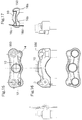
- FIGS. 1 through 4 An exemplary embodiment of a bicycle fork crown according to the principles of the present invention is illustrated in FIGS. 1 through 4 and identified by reference numeral 10.
- fork crown 10 includes a setting boss 12 and a connector holder 14.
- the connector holder 14 has an inlet 18, best shown in FIG. 4, for receiving an electrical cable 16a and an outlet 20, best shown in FIG. 1.
- the inlet 18 of the connector holder 14 is preferably dimensioned to securely receive electrical cables.
- an electrical connector 22 is used to electrically connect cable 16a with another cable 16b.
- the electrical connector 22 preferably has a first end 24 attachable to the outlet 20 of the connector holder 14 and a second end 26 dimensioned to receive electrical cable 16b.
- Connector 22 provides an electrical connection for cable 16a and 16b.
- cable 16a is connected to a motor and transmits code to and from the motor.
- the invention is not limited to cables that are connected to a particular motor or other electro-mechanical device. Rather, the invention can be utilized in any application wherein electrical cables are used.
- cable 16b is electrically connected to cables 16c and 16d via a connector cable terminal 28.
- Cable terminal 28 has various electrical ports 30 dimensioned to receive the electrical cables 16b, 16c and 16d.
- the cable terminal 28 has three ports 30 dimensioned to receive the three cables 16b, 16c, and 16d.
- the connector cable terminal can have any number of ports, as needed to accommodate the number of electrical cables that are required to be electrically connected.
- the setting boss 12 is dimensioned to receive the connector cable terminal 28 thereon.
- the setting boss 12 protrudes from the surface 32 of the fork crown and is integrally attached to the surface 32.
- the setting boss is shown as having a circular cross-section corresponding to a bore 34 in the connector cable terminal 28.
- the connector cable terminal 28 is preferably mounted on the setting boss 12 and secured thereto by a fastening device 36.
- the setting boss is internally threaded to correspond to the external threads on a fastening device 36.
- the connector cable terminal 28 is fastened to the setting boss 12 by engaging the threads of the fastening device 36 with the internal threads of the setting boss 12.
- the fastening device 36 is a setting screw.
- the connector cable terminal 28 and the centering boss 12 are shown in FIGS. 1 through 3 as having a circular cross-section. However, the invention is not limited as such and in various embodiment of the invention, the centering boss 12 and the connector cable terminal 28 can have any desired shape.
- FIGS. 5 though 8 illustrate an alternative embodiment of the present invention wherein a fork crown cover 100 is placed over the bicycle fork crown 10, and the setting boss 112 and connector holder 114 are attached to the fork crown cover 100, rather than the fork crown 10.
- the structure and electrical connections of the setting boss 112 and the connector holder 114 are substantially similar to those described in the embodiment of FIGS. 1 through 4.
- the connector holder 114 has an inlet 118 for receiving an electrical cable 116a and an outlet 120.
- the inlet 118 of the connector holder 114 is preferably dimensioned to securely receive electrical cables.
- An electrical connector 122 is used to electrically connect cable 116a with another cable 116b.
- the electrical connector 122 preferably has a first end 124 attachable to the outlet 120 of the connector holder 114 and a second end 126 dimensioned to receive electrical cable 116b.
- Connector 122 provides an electrical connection for cable 116a and 116b.
- cable 116b is electrically connected to cables 116c and 116d via a connector cable terminal 128.
- Cable terminal 128 has various electrical ports 130 dimensioned to receive the electrical cables 116b, 116c, and 116d.
- the cable terminal 128 has three ports 130 dimensioned to receive the three cables 116b, 116c, and 116d.
- the connector cable terminal 128 can have any number of ports, as needed to receive and connect electrical cables.
- the setting boss 112 is dimensioned to receive the connector cable terminal 128 thereon.
- the setting boss 112 protrudes from the surface 132 of the fork crown cover 100 and is integrally attached to the surface 132.
- the setting boss 112 is shown as having a circular cross-section corresponding to a bore 134 in the connector cable terminal 128.
- the connector cable terminal 128 is preferably mounted on the setting boss 112 and secured thereto by a fastening device 136.
- the setting boss 112 is internally threaded to correspond to the external threads on the fastening device 136.
- the connector cable terminal 128 is preferably fastened to the setting boss 112 by engaging the threads of the fastening device 136 with the internal threads of the setting boss 112.
- the fork crown cover 100 has a channel 138 defined therein for accessing the pre-load adjuster (not shown).
- the suspension system can be altered to account for the rider's weight. For example, for a light-weight rider, the spring of the suspension system can be adjusted for less pre-load. For a heavy-weight rider the spring of the suspension system can be adjusted to provide more pre-load.
- the channel 138 in the fork crown cover 100 allows easy access to the rider or dealer to adjust the pre-load of the spring.
- a cap 140 is provided to cover the access channel 138 when the pre-load adjustment mechanism is being used.
- the cap 140 is preferably dimensioned to cover the access to channel 138 and preferably includes a notch 142 therein to facilitate the removal of the cap 140 from the crown cover 100 when access to the channel 138 is desired.
- the fork crown cover 100 includes a fork crown lower cover 102 and a fork crown upper cover 104.
- the upper cover 104 preferably includes the setting boss 112 and connector holder 114.
- the crown cover 100 can include only the upper cover 104, leaving the fork crown 10 exposed to the environment from below.
- the fork crown 10 is better protected from rain, dust, dirt and other elements that could cause damage to the fork crown 10 or the suspension system generally.
- the lower cover 102 can be fastened to the fork crown 10 or to the upper crown 104 by any known fastening means.
- the lower cover 102 is fastened to the fork crown 10 using setting screws 106.
- Other known fastening devices can be used in place of setting screws 106.
- upper cover 104 includes a setting aperture 108 and the lower cover includes a flexible setting post 110 dimensioned to engage with the setting aperture 108.
- the flexible setting post preferably has a latch portion 111 that protrudes into the setting aperture 108 when the setting post 110 is engaged with the setting aperture 108.
- the latch portion 111 securely fastens the upper cover 104 to the lower cover 102 when the post 110 is engaged with the aperture 108.
- a cover 150 made of a soft material is used to cover the fork crown 10, generally, and the connector holder 14, specifically.
- the cover 150 is preferably made of an electrically insulative material and more preferably is made of rubber. Some of the benefits of the rubber cover 150 are that it is flexible, allowing for easy fitting over the fork crown, and inexpensive. Additionally, if using a rubber cover 150, the electrical connections can be bare code with rough connection, as shown in FIG. 17. By having bare code with rough connection, the need for an electrical connector 22 and a connector cable terminal 28 is eliminated, further reducing the assembly cost of the electrical connections.
Landscapes
- Engineering & Computer Science (AREA)
- Mechanical Engineering (AREA)
- Motorcycle And Bicycle Frame (AREA)
- Steering Devices For Bicycles And Motorcycles (AREA)
- Details Of Connecting Devices For Male And Female Coupling (AREA)
Abstract
Description
Claims (35)
- A bicycle fork crown (10) for holding electrical cables, comprising a connector holder (14) having an inlet (18) dimensioned to receive electrical cables (16a).
- A bicycle fork crown (10) in accordance with claim 1, further comprising:wherein the electrical connector (22) provides an electrical connection for electrical cables in the inlet (18) of the connector holder (14) to electrical cables in the second end (26) of the electrical connector (22).an outlet (20) defined in the connector holder (14);an electrical connector (22) having a first end (24) and a second end (26), the first end (24) of the electrical connector (22) attachable to the outlet (20) of the connector holder (14), the second end (26) of the electrical connector (22) dimensioned to receive electrical cables (16b); and
- A bicycle fork crown (10) in accordance with claim 1 or 2, further comprising a setting boss (12) located apart from the connector holder (14).
- A bicycle fork crown (10) in accordance with claim 3 wherein the setting boss (12) comprises a protrusion.
- A bicycle fork crown (10) in accordance with claim 4, further comprising:wherein the protrusion is integrally attached to the surface (32) of the bicycle fork crown (10).a surface (32) of the bicycle fork crown (10); and
- A bicycle fork crown (10) in accordance with claims 3 to 5 wherein the setting boss (12) defines an internally threaded bore.
- A bicycle fork crown (10) in accordance with claims 3 to 6, further comprising:wherein the setting boss (12) is dimensioned to receive the connector cable terminal (28);a connector cable terminal (28);wherein the connector cable terminal (28) is securely fastened on the setting boss (12) by tightening the threads of the fastening device (36) into the threads of the setting boss (12).a fastening device (36) having external threads corresponding to the internally threaded bore in the setting boss (12); and
- A bicycle fork crown (10) in accordance with claims 2 to 7, further comprising a cable connector terminal (28) electrically connected to the electrical connector (22).
- A bicycle fork crown (10) in accordance with any of the preceding claims, further comprising a cover (150) made of a soft material, the cover (150) covering the electrical connector.
- A bicycle fork crown (10) in accordance with claim 9 wherein the cover (150) is electrically insulative.
- A bicycle fork crown (10) in accordance with claim 9 or 10 wherein the cover (150) is made of rubber.
- A bicycle fork crown cover (100) for holding electrical cables, comprising a connector holder (114) having an inlet (118) dimensioned to receive electrical cables (116a).
- A bicycle fork crown cover (100) in accordance with claim 12, further comprising:wherein the electrical connector (122) provides an electrical connection for electrical cables in the inlet (118) of the connector holder (114) to electrical cables in the second end (126) of the electrical connector (122).an outlet (120) defined in the connector holder (114);an electrical connector (122) having a first end (124) and a second end (126), the first end of the electrical connector (122) attachable to the outlet (120) of the connector holder (114), the second end (126) of the electrical connector (122) dimensioned to receive electrical cables (116b); and
- A bicycle fork crown cover (100) in accordance with claim 12 or 13, further comprising a setting boss (112) located apart from the connector holder (114).
- A bicycle fork crown cover (100) in accordance with claim 14 wherein the setting boss (112) comprises a protrusion.
- A bicycle fork crown cover (100) in accordance with claim 15, further comprising:wherein the protrusion is integrally attached to the surface (132) of the bicycle fork crown cover (100).a surface (132) of the bicycle fork crown (10); and
- A bicycle fork crown cover (100) in accordance with claims 14 to 16 wherein the setting boss (112) defines an internally threaded bore.
- A bicycle fork crown cover (100) in accordance with claims 14 to 17, further comprising:wherein the setting boss (112) is dimensioned to receive the connector cable terminal (128);a connector cable terminal (128);wherein the connector cable terminal (128) is securely fastened on the setting boss (112) by tightening the threads of the fastening device (136) into the threads of the setting boss (112).a fastening device (136) having external threads corresponding to the internally threaded bore in the setting boss (112); and
- A bicycle fork crown cover (100) in accordance with claims 13 to 18, further comprising a cable connector terminal (128) electrically connected to the electrical connector (122).
- A bicycle fork crown cover (100) in accordance with claims 13 to 19, further comprising a pre-load adjuster cap (140).
- A bicycle fork crown cover (100), comprising:an upper cover (104);a lower cover (102) connected to the upper cover (104).
- A bicycle fork crown cover (100) in accordance with claim 21, wherein the lower cover (102) is connected to the upper cover (104) by a fastening device.
- A bicycle fork crown cover (100) in accordance with claim 21 or 22, wherein the upper cover (104) defines at least one setting apertures (108), wherein the lower cover (102) comprises at least one flexible setting post (110) dimensioned to engage with the at least one setting aperture (108), and wherein the lower cover (102) is connected to the upper cover (104) by engaging the at least one flexible setting post (110) with the at least one setting aperture (108).
- A method of connecting electrical cables, comprising the steps of:providing a bicycle fork crown (10) having a connector holder (14) and an electrical connector (22), wherein the connector holder (14) and electrical connector (22) each have at least two portals;electrically and mechanically connecting a cable (16b) to one of the portals in the electrical connector (22);electrically and mechanically connecting a cable (16a) to one of the portals in the connector holder (14); andelectrically and mechanically connecting the electrical connector (22) to one of the portals of the connector holder (14).
- A method in accordance with claim 24, further comprising the steps of:providing a setting boss (12) and a connector cable terminal (28) on the fork crown (10), wherein the setting boss is dimensioned to receive the connector cable terminal (28) thereon;electrically and mechanically connecting a cable (16b, 16c, 16d) to the connector cable terminal (28); andinstalling the connector cable terminal onto the setting boss (12).
- A method of connecting electrical cables, comprising the steps of:providing a bicycle crown cover (100) having a connector holder (114) and an electrical connector (122), wherein the connector holder (114) and electrical connector (122) each have at least two portals;electrically and mechanically connecting a cable (116b) to one of the portals in the electrical connector (122);electrically and mechanically connecting a cable (116a) to one of the portals in the connector holder (114); andelectrically and mechanically connecting the electrical connector (122) to one of the portals of the connector holder (114).
- A method in accordance with claim 26, further comprising the steps of:providing a setting boss (112) and a connector cable terminal (128) on the fork crown cover (100), wherein the setting boss is dimensioned to receive the connector cable terminal (128) thereon;electrically and mechanically connecting a cable (116b, 116c, 116d) to the connector cable terminal (128); andinstalling the connector cable terminal onto the setting boss (112).
- A bicycle fork crown assembly for holding electrical cables, comprising:a fork crown (10);a fork crown cover (100) covering the fork crown; anda connector holder (114) located on the fork crown cover (100) having an inlet (118) dimensioned to receive electrical cables.
- A bicycle fork crown assembly in accordance with claim 28, further comprising:wherein the electrical connector (122) provides an electrical connection for electrical cables in the inlet (118) of the connector holder (114) to electrical cables in the second end (126) of the electrical connector (122).an outlet (120) defined in the connector holder (114);an electrical connector (122) having a first end (124) and a second end (126), the first end of the electrical connector (122) attachable to the outlet (120) of the connector holder (114), the second end (126) of the electrical connector (122) dimensioned to receive electrical cables (116b); and
- A bicycle fork crown assembly in accordance with claim 28 or 29, further comprising a setting boss (112) located on the fork crown cover (100).
- A bicycle fork crown assembly in accordance with claim 30 wherein the setting boss (112) comprises a protrusion.
- A bicycle fork crown assembly in accordance with claim 31, further comprising:wherein the protrusion is integrally attached to the surface (132) of the fork crown cover (100).a surface (132) of the fork crown cover (100); and
- A bicycle fork crown assembly in accordance with claims 30 to 32 wherein the setting boss (112) defines an internally threaded bore.
- A bicycle fork crown assembly in accordance with claims 30 to 33, further comprising:wherein the setting boss (112) is dimensioned to receive the connector cable terminal (128);a connector cable terminal (128);wherein the connector cable terminal (128) is securely fastened on the setting boss (112) by tightening the threads of the fastening device (136) into the threads of the setting boss (112).a fastening device (136) having external threads corresponding to the internally threaded bore in the setting boss (112); and
- A bicycle fork crown assembly in accordance with claims 29 to 34, further comprising a cable connector terminal (128) electrically connected to the electrical connector (122).
Applications Claiming Priority (2)
| Application Number | Priority Date | Filing Date | Title |
|---|---|---|---|
| US661973 | 1976-02-27 | ||
| US09/661,973 US6609722B1 (en) | 2000-09-14 | 2000-09-14 | Bicycle crown or crown cover with electrical connector support |
Publications (3)
| Publication Number | Publication Date |
|---|---|
| EP1188655A2 true EP1188655A2 (en) | 2002-03-20 |
| EP1188655A3 EP1188655A3 (en) | 2003-07-09 |
| EP1188655B1 EP1188655B1 (en) | 2008-08-20 |
Family
ID=24655850
Family Applications (1)
| Application Number | Title | Priority Date | Filing Date |
|---|---|---|---|
| EP01122000A Expired - Lifetime EP1188655B1 (en) | 2000-09-14 | 2001-09-13 | Bicycle fork crown |
Country Status (6)
| Country | Link |
|---|---|
| US (3) | US6609722B1 (en) |
| EP (1) | EP1188655B1 (en) |
| JP (1) | JP3572280B2 (en) |
| CN (1) | CN1343599A (en) |
| DE (1) | DE60135421D1 (en) |
| TW (1) | TW544423B (en) |
Cited By (1)
| Publication number | Priority date | Publication date | Assignee | Title |
|---|---|---|---|---|
| EP1491433A1 (en) * | 2003-06-27 | 2004-12-29 | Shimano Inc. | Bicycle front end arrangement forming electric power supply system |
Families Citing this family (26)
| Publication number | Priority date | Publication date | Assignee | Title |
|---|---|---|---|---|
| US6609722B1 (en) * | 2000-09-14 | 2003-08-26 | Shimano Inc. | Bicycle crown or crown cover with electrical connector support |
| US6592136B2 (en) | 2001-07-02 | 2003-07-15 | Fox Factory, Inc. | Bicycle fork cartridge assembly |
| US7128192B2 (en) | 2001-08-30 | 2006-10-31 | Fox Factory, Inc. | Inertia valve shock absorber |
| US7273137B2 (en) | 2001-08-30 | 2007-09-25 | Fox Factory, Inc. | Inertia valve shock absorber |
| US6734376B2 (en) * | 2002-06-19 | 2004-05-11 | Shimano Inc. | Electrical switch device for bicycle |
| US10941828B2 (en) | 2002-06-25 | 2021-03-09 | Fox Factory, Inc. | Gas spring with travel control |
| US7703585B2 (en) * | 2002-06-25 | 2010-04-27 | Fox Factory, Inc. | Integrated and self-contained suspension assembly having an on-the-fly adjustable air spring |
| US8464850B2 (en) | 2006-11-16 | 2013-06-18 | Fox Factory, Inc. | Gas spring curve control in an adjustable-volume gas-pressurized device |
| US20080296814A1 (en) | 2002-06-25 | 2008-12-04 | Joseph Franklin | Gas spring with travel control |
| US7963509B2 (en) | 2007-01-31 | 2011-06-21 | Fox Factory, Inc. | Travel control for a gas spring and gas spring having very short travel modes |
| US7216881B2 (en) * | 2003-11-21 | 2007-05-15 | Sram Corporation | Cable guide for a bicycle suspension fork |
| US20080306054A1 (en) * | 2005-04-13 | 2008-12-11 | Astex Therapeutics Limited | Pharmaceutical Compounds |
| US7699146B1 (en) | 2006-04-02 | 2010-04-20 | Fox Factory, Inc. | Suspension damper having inertia valve and user adjustable pressure-relief |
| JP5861078B2 (en) * | 2011-09-02 | 2016-02-16 | パナソニックIpマネジメント株式会社 | Connector storage case and bicycle |
| CN102390472A (en) * | 2011-10-13 | 2012-03-28 | 无锡东南车辆科技有限公司 | Controller installation device for electric power bicycles |
| US9242693B2 (en) | 2013-03-15 | 2016-01-26 | Darrell W. Voss | Bicycle rear suspension |
| USD737730S1 (en) * | 2013-10-31 | 2015-09-01 | Shinola/Detroit, LLC | Fork crown |
| EP3114019B1 (en) | 2014-03-03 | 2021-08-18 | Darrell W. Voss | Vehicle terrain-tracking systems |
| US10061302B2 (en) | 2015-06-18 | 2018-08-28 | 3D Systems, Inc. | 3D printing waste material handling and transfer |
| US10029756B2 (en) | 2015-07-14 | 2018-07-24 | Duncan Bayard STOTHERS | Impact absorbing support for a wheel |
| USD862362S1 (en) | 2016-12-05 | 2019-10-08 | Rackstar, Llc | Bicycle protective cover |
| US10870461B2 (en) * | 2017-03-23 | 2020-12-22 | Darrell W. Voss | Vehicle component |
| US10723410B2 (en) | 2017-03-23 | 2020-07-28 | Darrell W Voss | Vehicle |
| US10457349B2 (en) | 2017-03-23 | 2019-10-29 | Darrell W. Voss | Vehicle component |
| US11548587B2 (en) | 2017-03-23 | 2023-01-10 | Darrell W Voss | Vehicle |
| US10618595B2 (en) | 2017-03-23 | 2020-04-14 | Darrell W Voss | Vehicle |
Family Cites Families (34)
| Publication number | Priority date | Publication date | Assignee | Title |
|---|---|---|---|---|
| US545948A (en) * | 1895-09-10 | William de lany | ||
| NL61039C (en) * | 1900-01-01 | |||
| DE419506C (en) * | 1924-01-19 | 1925-10-05 | Fritz Hecht | Clevis for bicycles and motorcycles |
| US1603171A (en) * | 1924-05-17 | 1926-10-12 | Wade Charles | Trouble lamp |
| US1995795A (en) * | 1934-05-17 | 1935-03-26 | Westifield Mfg Company | Casing for bicycle accessories |
| FR951432A (en) * | 1942-08-01 | 1949-10-25 | Metallwerk Alfred Schwarz G M | Cable guide device for cycles and motorcycles |
| CH268729A (en) | 1947-02-04 | 1950-05-31 | Johannes Van Kleffens Eelco | Frames for bicycles and similar vehicles with conductor conductors arranged therein for an electric lighting device. |
| FR1006862A (en) * | 1949-12-05 | 1952-04-28 | Method of manufacturing the front fork connector in bicycles, tandems and similar vehicles | |
| DE920650C (en) | 1950-07-23 | 1954-11-25 | Martin Schlueter | Cable connection to the rear light of bicycles or the like. |
| US3331617A (en) * | 1965-04-01 | 1967-07-18 | American Mach & Foundry | Handle bar construction |
| US3513926A (en) * | 1968-01-23 | 1970-05-26 | Richard E Paget Jr | Two-wheeled foldable personnel transporter |
| CA986811A (en) * | 1971-10-21 | 1976-04-06 | Telesco Brophey Limited | Telescopic umbrella stick |
| US3831979A (en) * | 1971-11-04 | 1974-08-27 | Ashtabula Bow Socket Co | Steering assembly |
| DE2326504C3 (en) * | 1973-05-24 | 1978-05-11 | Julius Sprick Kg, 4830 Guetersloh | Bicycle clevis |
| US4168097A (en) * | 1977-12-28 | 1979-09-18 | Doll Ronald L | Wind shield adapter for motorcycle fairing |
| US4512567A (en) * | 1983-03-28 | 1985-04-23 | Phillips Robert V | Exercise bicycle apparatus particularly adapted for controlling video games |
| US4640572A (en) * | 1984-08-10 | 1987-02-03 | Conlon Thomas R | Connector for structural systems |
| JPS62146787A (en) | 1985-12-20 | 1987-06-30 | 本田技研工業株式会社 | Anti-mud structure for front fenders of motorcycles, etc. |
| JPS62148787A (en) | 1985-12-23 | 1987-07-02 | 三和シヤツタ−工業株式会社 | shutter |
| US5222752A (en) * | 1991-11-04 | 1993-06-29 | Hewitt George L | Fairing and utility assembly for bicycles |
| US5239147A (en) * | 1992-08-03 | 1993-08-24 | Morton International, Inc. | Floating, serviceable horn switch, air bag modules |
| JP3252235B2 (en) * | 1992-10-08 | 2002-02-04 | ヤマハ発動機株式会社 | Motorcycle connector housing device |
| US5484799A (en) * | 1993-12-09 | 1996-01-16 | Abbott Laboratories | Antifungal dorrigocin derivatives |
| US5562297A (en) * | 1995-12-12 | 1996-10-08 | Lin; Chun-San | Engagement between a connecting element and a front fork |
| US5820254A (en) * | 1996-01-16 | 1998-10-13 | Duenas; Mark | Removable motorcycle light |
| US5848799A (en) | 1997-03-26 | 1998-12-15 | Huan; Su-We | Fork blade packing structure for a bicycle front fork |
| JP3382832B2 (en) * | 1997-11-27 | 2003-03-04 | 川崎重工業株式会社 | Mounted four-wheel rough terrain vehicle |
| JP3494907B2 (en) * | 1998-11-27 | 2004-02-09 | 本田技研工業株式会社 | Motorcycle lighting system |
| US6189905B1 (en) * | 1999-01-07 | 2001-02-20 | Gt Bicycles, Inc. | Shock absorbing bicycle with pressurized air supply system |
| US6095542A (en) * | 1999-02-22 | 2000-08-01 | Answer Products, Inc. | Light-weight bicycle crown containing lightening bores |
| US6609722B1 (en) * | 2000-09-14 | 2003-08-26 | Shimano Inc. | Bicycle crown or crown cover with electrical connector support |
| US6600411B2 (en) * | 2001-03-09 | 2003-07-29 | Shimano Inc. | Bicycle electrical connector cord |
| US6659489B2 (en) * | 2001-10-26 | 2003-12-09 | Shimano Inc. | Cover assembly for portions of bicycle |
| US6709000B1 (en) * | 2002-05-31 | 2004-03-23 | Pacific Cycle Llc | Simplified training wheel-to-frame mounting assembly bicycle |
-
2000
- 2000-09-14 US US09/661,973 patent/US6609722B1/en not_active Expired - Lifetime
-
2001
- 2001-09-12 JP JP2001276197A patent/JP3572280B2/en not_active Expired - Fee Related
- 2001-09-13 TW TW090122776A patent/TW544423B/en not_active IP Right Cessation
- 2001-09-13 CN CN01133010A patent/CN1343599A/en active Pending
- 2001-09-13 DE DE60135421T patent/DE60135421D1/en not_active Expired - Lifetime
- 2001-09-13 EP EP01122000A patent/EP1188655B1/en not_active Expired - Lifetime
-
2003
- 2003-05-20 US US10/444,893 patent/US6976692B2/en not_active Expired - Fee Related
- 2003-05-20 US US10/444,729 patent/US6902426B2/en not_active Expired - Fee Related
Cited By (2)
| Publication number | Priority date | Publication date | Assignee | Title |
|---|---|---|---|---|
| EP1491433A1 (en) * | 2003-06-27 | 2004-12-29 | Shimano Inc. | Bicycle front end arrangement forming electric power supply system |
| US6974144B2 (en) | 2003-06-27 | 2005-12-13 | Shimano, Inc. | Bicycle front end arrangement forming electric power supply system |
Also Published As
| Publication number | Publication date |
|---|---|
| US20040110405A1 (en) | 2004-06-10 |
| US6976692B2 (en) | 2005-12-20 |
| JP3572280B2 (en) | 2004-09-29 |
| JP2002127980A (en) | 2002-05-09 |
| DE60135421D1 (en) | 2008-10-02 |
| CN1343599A (en) | 2002-04-10 |
| EP1188655B1 (en) | 2008-08-20 |
| US6609722B1 (en) | 2003-08-26 |
| US20050012297A1 (en) | 2005-01-20 |
| US6902426B2 (en) | 2005-06-07 |
| EP1188655A3 (en) | 2003-07-09 |
| TW544423B (en) | 2003-08-01 |
Similar Documents
| Publication | Publication Date | Title |
|---|---|---|
| EP1188655B1 (en) | Bicycle fork crown | |
| CA2315428C (en) | Electrical utility box | |
| EP0823556A3 (en) | Ceiling fan hanging system | |
| EP1276192A1 (en) | Intermediate connection unit usable on board of a bicycle | |
| WO2015148551A1 (en) | Housing for breakout cords terminated to plates | |
| US5771575A (en) | Automobile instrument panel harness-connecting construction | |
| GB2572466A (en) | Battery holder | |
| US4676569A (en) | Protective cover for cable television distribution taps | |
| EP3470316A1 (en) | Grip for a bike | |
| US20020158524A1 (en) | Method and apparatus for mounting electronic motor controls | |
| CA2276639A1 (en) | Wiring device with gripping of individual conductors | |
| US20060094294A1 (en) | Connector for joining cable conductors with an antenna | |
| US5229675A (en) | Output-terminal device for an a.c. generator for a vehicle | |
| CA1281698C (en) | Twist-lock tool-operable panel traversing sleeve for cables | |
| CA2096040A1 (en) | Vehicle wiring harness with wiring harness | |
| US5266857A (en) | Output-terminal device for an a.c. generator for a vehicle | |
| US5971337A (en) | Bolt falling prevention holder | |
| US5713757A (en) | Assembly for supplying power | |
| EP0853369A3 (en) | A system for connecting an electrical cable at a predetermined angle to a terminal of electrical apparatus, in particular an alternator for a motor vehicle | |
| EP0931704A3 (en) | Harness cover for electrical connection box and assembly including it | |
| GB2244604A (en) | Terminal block arrangements in a three-phase alternator | |
| KR200157507Y1 (en) | Protector for fixing wire harness and connector | |
| KR102610777B1 (en) | Corrosion preventing device for multi-earth terminal | |
| JP2712499B2 (en) | Cabinet equipment | |
| EP1098402B1 (en) | Door with support panel for electrical components |
Legal Events
| Date | Code | Title | Description |
|---|---|---|---|
| PUAI | Public reference made under article 153(3) epc to a published international application that has entered the european phase |
Free format text: ORIGINAL CODE: 0009012 |
|
| AK | Designated contracting states |
Kind code of ref document: A2 Designated state(s): AT BE CH CY DE DK ES FI FR GB GR IE IT LI LU MC NL PT SE TR |
|
| AX | Request for extension of the european patent |
Free format text: AL;LT;LV;MK;RO;SI |
|
| RIC1 | Information provided on ipc code assigned before grant |
Ipc: 7B 62J 6/18 B Ipc: 7B 62K 21/04 A |
|
| PUAL | Search report despatched |
Free format text: ORIGINAL CODE: 0009013 |
|
| 17P | Request for examination filed |
Effective date: 20030410 |
|
| AK | Designated contracting states |
Designated state(s): AT BE CH CY DE DK ES FI FR GB GR IE IT LI LU MC NL PT SE TR |
|
| AX | Request for extension of the european patent |
Extension state: AL LT LV MK RO SI |
|
| AKX | Designation fees paid |
Designated state(s): DE FR GB IE IT NL |
|
| RAP1 | Party data changed (applicant data changed or rights of an application transferred) |
Owner name: SHIMANO INC. |
|
| GRAP | Despatch of communication of intention to grant a patent |
Free format text: ORIGINAL CODE: EPIDOSNIGR1 |
|
| GRAS | Grant fee paid |
Free format text: ORIGINAL CODE: EPIDOSNIGR3 |
|
| GRAA | (expected) grant |
Free format text: ORIGINAL CODE: 0009210 |
|
| AK | Designated contracting states |
Kind code of ref document: B1 Designated state(s): DE FR GB IE IT NL |
|
| REG | Reference to a national code |
Ref country code: GB Ref legal event code: FG4D |
|
| REG | Reference to a national code |
Ref country code: IE Ref legal event code: FG4D |
|
| REF | Corresponds to: |
Ref document number: 60135421 Country of ref document: DE Date of ref document: 20081002 Kind code of ref document: P |
|
| REG | Reference to a national code |
Ref country code: IE Ref legal event code: MM4A |
|
| PLBE | No opposition filed within time limit |
Free format text: ORIGINAL CODE: 0009261 |
|
| STAA | Information on the status of an ep patent application or granted ep patent |
Free format text: STATUS: NO OPPOSITION FILED WITHIN TIME LIMIT |
|
| 26N | No opposition filed |
Effective date: 20090525 |
|
| GBPC | Gb: european patent ceased through non-payment of renewal fee |
Effective date: 20081120 |
|
| PG25 | Lapsed in a contracting state [announced via postgrant information from national office to epo] |
Ref country code: IE Free format text: LAPSE BECAUSE OF NON-PAYMENT OF DUE FEES Effective date: 20080913 |
|
| PG25 | Lapsed in a contracting state [announced via postgrant information from national office to epo] |
Ref country code: IT Free format text: LAPSE BECAUSE OF FAILURE TO SUBMIT A TRANSLATION OF THE DESCRIPTION OR TO PAY THE FEE WITHIN THE PRESCRIBED TIME-LIMIT Effective date: 20080820 |
|
| REG | Reference to a national code |
Ref country code: FR Ref legal event code: ST Effective date: 20090731 |
|
| PG25 | Lapsed in a contracting state [announced via postgrant information from national office to epo] |
Ref country code: GB Free format text: LAPSE BECAUSE OF NON-PAYMENT OF DUE FEES Effective date: 20081120 |
|
| PGFP | Annual fee paid to national office [announced via postgrant information from national office to epo] |
Ref country code: NL Payment date: 20090915 Year of fee payment: 9 |
|
| REG | Reference to a national code |
Ref country code: NL Ref legal event code: V1 Effective date: 20110401 |
|
| PG25 | Lapsed in a contracting state [announced via postgrant information from national office to epo] |
Ref country code: NL Free format text: LAPSE BECAUSE OF NON-PAYMENT OF DUE FEES Effective date: 20110401 |
|
| PG25 | Lapsed in a contracting state [announced via postgrant information from national office to epo] |
Ref country code: FR Free format text: LAPSE BECAUSE OF NON-PAYMENT OF DUE FEES Effective date: 20081020 |
|
| PGFP | Annual fee paid to national office [announced via postgrant information from national office to epo] |
Ref country code: DE Payment date: 20150908 Year of fee payment: 15 |
|
| REG | Reference to a national code |
Ref country code: DE Ref legal event code: R119 Ref document number: 60135421 Country of ref document: DE |
|
| PG25 | Lapsed in a contracting state [announced via postgrant information from national office to epo] |
Ref country code: DE Free format text: LAPSE BECAUSE OF NON-PAYMENT OF DUE FEES Effective date: 20170401 |