EP1188568A1 - Ink-jet recorder - Google Patents
Ink-jet recorder Download PDFInfo
- Publication number
- EP1188568A1 EP1188568A1 EP01915809A EP01915809A EP1188568A1 EP 1188568 A1 EP1188568 A1 EP 1188568A1 EP 01915809 A EP01915809 A EP 01915809A EP 01915809 A EP01915809 A EP 01915809A EP 1188568 A1 EP1188568 A1 EP 1188568A1
- Authority
- EP
- European Patent Office
- Prior art keywords
- recording
- ink
- ink jet
- set forth
- jet recording
- Prior art date
- Legal status (The legal status is an assumption and is not a legal conclusion. Google has not performed a legal analysis and makes no representation as to the accuracy of the status listed.)
- Granted
Links
- 238000007639 printing Methods 0.000 claims abstract description 25
- 239000003086 colorant Substances 0.000 claims description 4
- 238000012423 maintenance Methods 0.000 claims description 3
- 238000010276 construction Methods 0.000 description 5
- 238000010586 diagram Methods 0.000 description 4
- VYPSYNLAJGMNEJ-UHFFFAOYSA-N Silicium dioxide Chemical compound O=[Si]=O VYPSYNLAJGMNEJ-UHFFFAOYSA-N 0.000 description 3
- XAGFODPZIPBFFR-UHFFFAOYSA-N aluminium Chemical compound [Al] XAGFODPZIPBFFR-UHFFFAOYSA-N 0.000 description 3
- 229910052782 aluminium Inorganic materials 0.000 description 3
- 230000015572 biosynthetic process Effects 0.000 description 3
- -1 polyethylene Polymers 0.000 description 3
- 238000011084 recovery Methods 0.000 description 3
- 229910052814 silicon oxide Inorganic materials 0.000 description 3
- 239000002699 waste material Substances 0.000 description 3
- 239000004698 Polyethylene Substances 0.000 description 2
- 238000007599 discharging Methods 0.000 description 2
- 239000005001 laminate film Substances 0.000 description 2
- 229920000573 polyethylene Polymers 0.000 description 2
- 229920000139 polyethylene terephthalate Polymers 0.000 description 2
- 239000005020 polyethylene terephthalate Substances 0.000 description 2
- 239000002904 solvent Substances 0.000 description 2
- 239000004677 Nylon Substances 0.000 description 1
- 230000003213 activating effect Effects 0.000 description 1
- 230000004888 barrier function Effects 0.000 description 1
- 238000006073 displacement reaction Methods 0.000 description 1
- 238000001035 drying Methods 0.000 description 1
- 238000001914 filtration Methods 0.000 description 1
- 239000011888 foil Substances 0.000 description 1
- 230000006870 function Effects 0.000 description 1
- 230000001939 inductive effect Effects 0.000 description 1
- 239000007788 liquid Substances 0.000 description 1
- 239000000463 material Substances 0.000 description 1
- 238000000034 method Methods 0.000 description 1
- 229920001778 nylon Polymers 0.000 description 1
- 229920006284 nylon film Polymers 0.000 description 1
- 230000003287 optical effect Effects 0.000 description 1
- 238000007789 sealing Methods 0.000 description 1
- 238000000926 separation method Methods 0.000 description 1
- 238000011144 upstream manufacturing Methods 0.000 description 1
- 238000009834 vaporization Methods 0.000 description 1
- 230000008016 vaporization Effects 0.000 description 1
- 238000003466 welding Methods 0.000 description 1
Images


Classifications
-
- B—PERFORMING OPERATIONS; TRANSPORTING
- B41—PRINTING; LINING MACHINES; TYPEWRITERS; STAMPS
- B41J—TYPEWRITERS; SELECTIVE PRINTING MECHANISMS, i.e. MECHANISMS PRINTING OTHERWISE THAN FROM A FORME; CORRECTION OF TYPOGRAPHICAL ERRORS
- B41J2/00—Typewriters or selective printing mechanisms characterised by the printing or marking process for which they are designed
- B41J2/005—Typewriters or selective printing mechanisms characterised by the printing or marking process for which they are designed characterised by bringing liquid or particles selectively into contact with a printing material
- B41J2/01—Ink jet
- B41J2/17—Ink jet characterised by ink handling
- B41J2/175—Ink supply systems ; Circuit parts therefor
- B41J2/17503—Ink cartridges
- B41J2/17513—Inner structure
-
- B—PERFORMING OPERATIONS; TRANSPORTING
- B41—PRINTING; LINING MACHINES; TYPEWRITERS; STAMPS
- B41J—TYPEWRITERS; SELECTIVE PRINTING MECHANISMS, i.e. MECHANISMS PRINTING OTHERWISE THAN FROM A FORME; CORRECTION OF TYPOGRAPHICAL ERRORS
- B41J2/00—Typewriters or selective printing mechanisms characterised by the printing or marking process for which they are designed
- B41J2/005—Typewriters or selective printing mechanisms characterised by the printing or marking process for which they are designed characterised by bringing liquid or particles selectively into contact with a printing material
- B41J2/01—Ink jet
- B41J2/17—Ink jet characterised by ink handling
- B41J2/175—Ink supply systems ; Circuit parts therefor
-
- B—PERFORMING OPERATIONS; TRANSPORTING
- B41—PRINTING; LINING MACHINES; TYPEWRITERS; STAMPS
- B41J—TYPEWRITERS; SELECTIVE PRINTING MECHANISMS, i.e. MECHANISMS PRINTING OTHERWISE THAN FROM A FORME; CORRECTION OF TYPOGRAPHICAL ERRORS
- B41J2/00—Typewriters or selective printing mechanisms characterised by the printing or marking process for which they are designed
- B41J2/005—Typewriters or selective printing mechanisms characterised by the printing or marking process for which they are designed characterised by bringing liquid or particles selectively into contact with a printing material
- B41J2/01—Ink jet
- B41J2/17—Ink jet characterised by ink handling
- B41J2/175—Ink supply systems ; Circuit parts therefor
- B41J2/17503—Ink cartridges
- B41J2/17506—Refilling of the cartridge
- B41J2/17509—Whilst mounted in the printer
-
- B—PERFORMING OPERATIONS; TRANSPORTING
- B41—PRINTING; LINING MACHINES; TYPEWRITERS; STAMPS
- B41J—TYPEWRITERS; SELECTIVE PRINTING MECHANISMS, i.e. MECHANISMS PRINTING OTHERWISE THAN FROM A FORME; CORRECTION OF TYPOGRAPHICAL ERRORS
- B41J3/00—Typewriters or selective printing or marking mechanisms characterised by the purpose for which they are constructed
- B41J3/54—Typewriters or selective printing or marking mechanisms characterised by the purpose for which they are constructed with two or more sets of type or printing elements
- B41J3/543—Typewriters or selective printing or marking mechanisms characterised by the purpose for which they are constructed with two or more sets of type or printing elements with multiple inkjet print heads
Definitions
- the present invention relates to a recording apparatus which incorporates an ink jet recording head for ejecting ink droplets.
- High-speed printing of large volume documents has been performed by use of a page printer equipped with a xerographic recording engine.
- the page printer poses a problem of an increase in power consumption and noise in association with the high-speed characteristic of the page printer, as well as a problem of a complex structure which deteriorates reliability.
- the recording apparatus of the former construction enables an increase in printing speed.
- complicated maintenance is required.
- the recording apparatus of the latter construction requires design of a recording head with a new configuration, thereby incurring initial costs.
- U.S. Patent No. 5,596,416 has proposed that a controller collectively control a plurality of recording apparatuses having the same construction provided in a rack.
- the technique enables use of general-purpose recording apparatuses, thereby reducing costs.
- the ink jet recording apparatus cannot be employed hastily as such a general-purpose apparatus.
- ink jet recording apparatuses for general use are constructed such that ink cartridges are provided on a carriage. Hence, restrictions are imposed on the amount of ink for ensuring a carriage speed. In the field of applications where a large volume of print products are produced commercially, much time is required for replenishing the cartridges with ink.
- an ink jet recording apparatus comprising:
- ink can be supplied to the respective recording engines from a common main tank even when commercially-available general-purpose apparatuses are used as recording engines. As a result, replenishment the ink cartridges with ink and management of ink become simple.
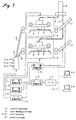
- Fig. 1 shows one embodiment of the present invention.
- Ink jet recording heads 1 and 1' are mounted on carriages 2 and 2' for ejecting ink droplets from nozzle orifices.
- Recording engines 3 and 3' perform printing operation by moving the recording heads 1 and 1' back and forth in a widthwise direction of a recording medium.
- the recording engines 3 and 3' are arranged so as to oppose to sheet transporting paths 4 and 4', respectively.
- the recording engines 3 and 3' are connected to a common main tank 6 via ink supply tubes 5 and 5', respectively.
- Cut sheet feeders 7 and 7' are disposed upstream of the recording sheet transport paths 4 and 4', respectively.
- a sorter 9 having sheet collation and sheet sorting functions is disposed downstream of the paper transport.paths 4 and 4' via sheet discharging paths 8 and 8'.
- a central controller 10 receives print data via a communications line 12 such as a LAN connected to an interface 11. When a predetermined reference volume of data; for example, print data pertaining to 3 pages or more, have been input to the central controller 10, the print data are divided into pages determined by format data.
- a sheet feeding controller 13 supplies sheets from the respective cut sheet feeders 7 and 7' to the recording engines 3 and 3'. Recording controller 14 and 14' cause the recording engines 3 and 3' to perform printing operation, and a sorter controller 15 controls the sorter 9 so as to collate printed sheets and discharging the sheets to trays 9a.
- the central controller 10 selects the recording engine 3. Print data is output to the print controller 14, thereby causing the recording apparatus to perform printing operation. The thus-printed recording sheet is sorted and output to a specific tray 9a by the sorter 9.
- the central controller 10 determines the volume of input print data.
- the print data is associated with several pages, the data is divided into page data determined by a print format. Consecutive pages; that is, two pages in the embodiment, are output from the print controller 14 and 14'.
- the sheet feeding controller 13 supplies recording sheets to the recording engines 3 and 3' from the cut sheet feeders 7 and 7'.
- the first control engine 3 prints a first page
- the second control engine 3' prints a second page.
- the sorter controller 15 controls the sorter 9. The thus-printed recording sheets are collated and output to the trays 9a.
- the central controller 10 assigns subsequent pages; that is, a third page and a fourth page, to the print controller 14 and 14', thereby performing printing operation.
- the central controller 10 selects a recording engine that is currently idle; e.g., the second recording engine 3', and print data are output to the print controller 14'.
- the sheet feeding controller 13 supplies a recording sheet from the sheet feeder 7' of the recording engine 3'.
- the central controller 10 determines whether or not any of the recording engines are currently idle. In this case, the first recording engine 3 is currently idle, and the input print data is output to the print controller 14.
- the sheet feeding controller 13 causes the sheet feeder 7 to supply a recording sheet to the recording engine 3, thereby performing printing operation.
- the recording sheets that have finished undergoing printing are divided into and output to different trays 9a by the sorter controller 15.
- one recording engine prints image data, and another recording engine consecutively prints a plurality of pages.
- recording engines can be operated asynchronously.
- the present embodiment has described a case where a plurality of PCs are connected together by way of a LAN. It is also evident that the present embodiment can be applied to a case where the recording apparatus is connected directly to a parallel port of a PC by changing the interface connector.
- an information reader for reading information from storage medium such as "compact flash memory” or “smart media”
- a display for displaying the information read by the reader and a print instruction provider are integrated together.
- Fig. 2 shows one embodiment of a system suitable for supplying ink from a single main tank to a plurality of recording engines.
- ink is supplied from the single main tank 6 to three recording engines.
- the recording engines 3, 3' and 3" are equipped with subtanks 20, 20' and 20", respectively.
- the recording heads 1, 1' and 1" are provided with ink supply from the common main tank 6 by way of the subtanks 20, 20' and 20", respectively.
- the subtanks 20, 20' and 20" are connected to a main tube 22 by way of electro-magnetic valves 24, 24' and 24", respectively.
- the main tube 22 is connected to an ink supply port 6a of the common main tank 6 by way of a main electro-magnetic valve 23.
- the main tank 6 is constituted of a flexible bag and is removably housed in an airtight container 25 to which air is supplied from an air pump 21.
- air is supplied to the airtight container 25 from the air pump 21, thereby effecting forcible discharge of ink.
- Reference numeral 26 designates an accumulator which prevents fluctuations in pressure of the air pump 21.
- a central controller 27 is connected to the print controller 14, 14', and 14" of the respective recording engine 3, 3', and 3".
- the central controller 27 controls operation of the air pump 21 upon receipt of ink level signals from the print controller 14, 14', and 14".
- the print controller 14, 14', and 14" control the electro-magnetic valves 24, 24', and 24" in accordance with an ink level detector provided in the respective subtanks 20, 20', and 20", thereby selectively supplying ink to desired subtanks from the common main tank 6.
- Figs. 3A, 3B and 4 show one embodiment of the subtank.
- the subtank 20 is taken as an example.
- the subtank 20 comprises: an airtight bag 30 having a capacity of 100-300 cc, which is a size allowing flexible volume change in accordance with change of ink amount therein; an inlet port 31 connected to the main tube 22 and an outlet port 32 connected to the recording head, which are provided in opposing sides of the bag 30.
- An aluminum laminate film can be used for the bag 30.
- the laminate film is made by taking, e.g., aluminum foil as an intermediate layer for ensuring gas barrier characteristics, and sandwiching the aluminum film between two films; e.g., an external nylon film and an internal polyethylene film.
- a translucent film can also be employed.
- Silicon oxide is deposited on the surface of a macromolecular film, such as a polyethylene terephthalate (PET) or nylon, having a translucent characteristic, as well as visibility and gas tightness, thereby forming a silicon oxide layer.
- a macromolecular film, such as polyethylene, having a superior thermal welding characteristic, is stacked on the surface of the silicon oxide layer, thereby forming the translucent film.
- a plate member 33 which is pivotable about one side edge 33a is brought into contact with the subtank 20 to form the ink level detector.
- the ink level detector 34 is constructed such that displacement of the other side edge 33b of the plate member 33 is detected by an electrical or optical sensor.
- Reference numeral 35 designates a fixation base.
- the central controller 27 Upon receipt of a print instruction, the central controller 27 sends an instruction to the print controller 14, 14', and 14" of the recording engines 3, 3', and 3". In accordance with the received print instruction, the print controller 14, 14', and 14" of the recording engines 3, 3', and 3" commence printing of delivered print data. On the basis of the signal output from the ink level detector 34, the amounts of ink remaining in the subtanks 20, 20', and 20" are checked periodically.
- the central controller 27 drives the air pump 21 and opens the main electro-magnetic valve 23.
- the print controller 14 of the recording engine 3 opens the electro-magnetic valve 24.
- the print controller 14 closes the electro-magnetic valve 24 and sends a signal to the central controller 27.
- the central controller 27 stops the air pump 21 and closes the main electro-magnetic valve 23.
- the central controller 27 drives the air pump 21 while the main electro-magnetic valve 23 is opened, until the central controller 27 receives an ink supply stop signal from all the recording engines.
- the central controller 27 informs the user of this situation and prompts replacement of the main tank 6. Even in this state, ink still remains in the subtanks 20, 20', and 20" of the recording engines 3, 3', and 3", and hence printing operation can be performed continuously. Thus, the user is required to control only the ink remaining in one main tank 6, thereby facilitating checking of the residual ink amount.
- ink is stably supplied to each recording head from each subtank. Since ink is forcibly supplied by the air pump 21, a positional relationship between the main tank 6 and the recording engines 3, 3', and 3" and a mutual positional relationship between the recording engines 3, 3', and 3" may be arranged in a horizontal or vertical direction.
- the ink jet recording head In an ink jet recording head, ink is ejected from narrow nozzle orifices. Hence, the nozzle orifices are likely to be clogged by drying of ink, thereby inducing print failures. For this reason, the ink jet recording head is provided with so-called an ejection recoverer. More specifically, the ejection recoverer seals a nozzle formation face of the recording head with a cap, and ink is forcibly discharged from the nozzle orifices by a suction pump.
- Fig. 5 shows an ink supply system provided with such an ejection recoverer.
- Capper 30, 30', and 30" for sealing nozzle formation face of the respective recording heads are disposed in non-printing areas on paths along which the recording heads 1, 1', and 1" of the recording engines 3, 3', and 3" travel.
- Suction ports of suction pumps 31, 31', and 31" are connected to the capper 30, 30', and 30".
- Discharge ports of the suction pumps 31, 31', and 31" are connected to an ink purifier 32.
- the ink purifier 32 houses a gas-liquid separation mechanism or a filter for filtering out air bubbles or foreign material contained in the ink output from the recording head.
- the ink purifier 32 is connected to a pump 33, and the ink output from the recording head is fed back to the main tank 6.
- the print controller 14, 14', and 14" move the recording heads 1, 1', and 1" to the positions-of. the capper 30, 30', and 30".
- the nozzle formation. face of the recording heads 1, 1', and 1" are closed by the capper 30, 30', and 30".
- the suction pumps 31, 31', and 31" are actuated, thereby causing the recording heads 1,1', and 1" to forcibly discharge ink.
- the foreign matter sticking to the nozzle orifices is flushed away with ink and flows into the ink purifier 32.
- the central controller 27 activates the pump 33, thereby recovering ink to the main tank 6.
- the recording heads 1, 1', and 1" can be maintained in a printable state at all times without involvement of unnecessary consumption of ink and without a necessity for disposing of wastes.
- the ink purifier 32 can completely remove foreign matter included in waste ink, the viscosity of ink is considered to increase as a result of vaporization of ink solvent. It is desirable to provide the main tank 6 or the ink purifier 32 with a mechanism for injecting an ink solvent therein.
- Fig. 6 shows a recording unit according to one embodiment of the present invention. At least the recording engine 3 is mounted on a table 40. A flow passage connector 41 and an electrical connector 42 are arranged on the table 40, thereby constructing a unit.
- the main connection port 45 of one recording unit is connected to the main tank by way of a tube 48, and the distribution port 47 is connected to the main connection port 45' of another recording unit.
- the distribution port 47' of the unit serving as a terminal is covered with a blank cap 49.
- each recording engine may be constructed as a plurality of independent recording heads.
- the recording engine can be constituted as a single recording head having a plurality of rows of nozzle orifices which can independently eject different types of ink.
- a recording engine is realized by a printing mechanism constituting a low-cost, reliable terminal printer. Further, simultaneous printing of a plurality of print data sets as well as high-speed printing operation. can be performed by independently activating individual recording engines.
- the recording engines can be assembled simply into a unit. Even if one print mechanism is in trouble, recovery can be easily effected by merely replacing one engine provided as a unit so that simplification of maintenance can be attained. In addition, if tables, flow passage connectors, and electrical connectors are constructed in compliance with identical specifications, unit addition can be easily performed.
Landscapes
- Ink Jet (AREA)
- Printers Characterized By Their Purpose (AREA)
- Particle Formation And Scattering Control In Inkjet Printers (AREA)
- Luminescent Compositions (AREA)
- Inks, Pencil-Leads, Or Crayons (AREA)
- Ink Jet Recording Methods And Recording Media Thereof (AREA)
Abstract
Description
Claims (12)
- An ink jet recording apparatus, comprising:a plurality of recording engines, each including an ink jet recording head mounted on a carriage, which ejects an ink droplet onto a recording sheet to perform printing; anda common main tank, to which the plural recording engines are connected via flow passages.
- The ink jet recording apparatus as set forth in claim 1, wherein each recording head is provided with a subtank, through which the recording head is communicated with the main tank.
- The ink jet recording apparatus as set forth in claim 1, wherein the subtank is mounted on the carriage together with the recording head.
- The ink jet recording apparatus as set forth in claim 2, wherein each subtank is connected to the main tank via an electrically actuated valve.
- The ink jet recording apparatus as set forth in claim 2, wherein the subtank is provided with a residual ink amount detector, and the main tank is provided with a pump which discharges ink in the main tank in accordance with a signal from the residual ink amount detector.
- The ink jet recording apparatus as set forth in claim 1, further comprising a controller which compares an amount of an externally provided print data with an amount of a reference data, wherein:the controller divides the print data into data sets, each corresponding to a predetermined amount of page, and provides the data sets to the plural recording engines, when the print data amount exceeds the reference data amount; andthe controller operates a single recording engine when the print data amount is less than the reference data amount.
- The ink jet recording apparatus as set forth in claim 1, further comprising a plurality of maintenance devices, each including at least a capper which is associated with each recording head.
- The ink jet recording apparatus as set forth in claim 1, further comprising a flow passage which returns ink discharged from the recording heads to the main tank.
- The ink jet recording apparatus as set forth in claim 1, wherein a plurality of main tanks are provided so as to be associated with a plurality of colors to be recorded.
- The ink jet recording apparatus as set forth in claim 1, further comprising a plurality of table units which are vertically stackable, each table unit including one recording engine and a flow passage connector which connects a recording head in the recording engine with either the main tank or another recording head.
- The ink jet recording apparatus as set forth in claim 1, wherein the recording engines are vertically arranged therein.
- The ink jet recording apparatus as set forth in claim 1, wherein at least one recording engine is used to perform black printing and the other recording engines are used to perform color printing.
Applications Claiming Priority (5)
| Application Number | Priority Date | Filing Date | Title |
|---|---|---|---|
| JP2000086020 | 2000-03-27 | ||
| JP2000086020 | 2000-03-27 | ||
| JP2001034187 | 2001-02-09 | ||
| JP2000034187 | 2001-02-09 | ||
| PCT/JP2001/002445 WO2001072522A1 (en) | 2000-03-27 | 2001-03-27 | Ink-jet recorder |
Publications (3)
| Publication Number | Publication Date |
|---|---|
| EP1188568A1 true EP1188568A1 (en) | 2002-03-20 |
| EP1188568A4 EP1188568A4 (en) | 2002-12-18 |
| EP1188568B1 EP1188568B1 (en) | 2006-05-03 |
Family
ID=26588391
Family Applications (1)
| Application Number | Title | Priority Date | Filing Date |
|---|---|---|---|
| EP01915809A Expired - Lifetime EP1188568B1 (en) | 2000-03-27 | 2001-03-27 | Ink-jet recorder |
Country Status (5)
| Country | Link |
|---|---|
| US (1) | US7316462B2 (en) |
| EP (1) | EP1188568B1 (en) |
| AT (1) | ATE324986T1 (en) |
| DE (1) | DE60119248T2 (en) |
| WO (1) | WO2001072522A1 (en) |
Cited By (1)
| Publication number | Priority date | Publication date | Assignee | Title |
|---|---|---|---|---|
| CN108778755A (en) * | 2016-05-26 | 2018-11-09 | 惠普发展公司,有限责任合伙企业 | Buffer |
Families Citing this family (13)
| Publication number | Priority date | Publication date | Assignee | Title |
|---|---|---|---|---|
| JP4579485B2 (en) * | 2002-06-24 | 2010-11-10 | セイコーエプソン株式会社 | Printing apparatus having a plurality of print heads |
| JP4147890B2 (en) * | 2002-10-11 | 2008-09-10 | セイコーエプソン株式会社 | Printing device |
| US7226143B2 (en) | 2002-10-11 | 2007-06-05 | Seiko Epson Corporation | Printing apparatus |
| US7357498B2 (en) * | 2003-12-24 | 2008-04-15 | Seiko Epson Corporation | Method of filling liquid into liquid containing member, liquid filling apparatus and method of inspecting liquid containing member |
| JP4305418B2 (en) * | 2005-06-13 | 2009-07-29 | 株式会社ミヤコシ | Ink supply apparatus in ink jet recording apparatus |
| JP4877213B2 (en) * | 2007-11-30 | 2012-02-15 | ブラザー工業株式会社 | Droplet ejector |
| JP4636116B2 (en) * | 2008-05-08 | 2011-02-23 | セイコーエプソン株式会社 | Printing device |
| JP5455755B2 (en) * | 2009-06-08 | 2014-03-26 | 株式会社セイコーアイ・インフォテック | Inkjet recording device |
| JP5162605B2 (en) * | 2010-01-28 | 2013-03-13 | 京セラドキュメントソリューションズ株式会社 | Liquid container |
| JP6368987B2 (en) * | 2013-03-29 | 2018-08-08 | ブラザー工業株式会社 | Recording device |
| JP6330429B2 (en) * | 2014-03-31 | 2018-05-30 | ブラザー工業株式会社 | Liquid ejection device |
| JP6384233B2 (en) | 2014-09-24 | 2018-09-05 | ブラザー工業株式会社 | Printing device |
| JP6337719B2 (en) | 2014-09-24 | 2018-06-06 | ブラザー工業株式会社 | Printing device |
Family Cites Families (24)
| Publication number | Priority date | Publication date | Assignee | Title |
|---|---|---|---|---|
| JPS5345723B2 (en) * | 1973-12-03 | 1978-12-08 | ||
| JPS5345723A (en) | 1976-10-06 | 1978-04-24 | Yoneda Kogyo Kk | Two ways branch ball valve |
| JPS5857962A (en) | 1981-10-02 | 1983-04-06 | Canon Inc | ink supply device |
| JPH04358844A (en) * | 1991-06-05 | 1992-12-11 | Canon Inc | inkjet recording device |
| US5428375A (en) * | 1992-05-29 | 1995-06-27 | Simon; Robert J. | Multiple print head ink jet printer |
| JP2835917B2 (en) | 1993-12-31 | 1998-12-14 | 株式会社トーショー | Medicine bag printing device |
| US5596416A (en) | 1994-01-13 | 1997-01-21 | T/R Systems | Multiple printer module electrophotographic printing device |
| JP3218843B2 (en) | 1994-03-18 | 2001-10-15 | 株式会社日立製作所 | Printing system |
| US5587730A (en) * | 1994-09-30 | 1996-12-24 | Xerox Corporation | Redundant full width array thermal ink jet printing for improved reliability |
| US5988782A (en) * | 1995-04-07 | 1999-11-23 | Canon Kabushiki Kaisha | Ink-jet printing apparatus |
| JP3684022B2 (en) * | 1996-04-25 | 2005-08-17 | キヤノン株式会社 | Liquid replenishment method, liquid discharge recording apparatus, and ink tank used as a main tank of the liquid discharge recording apparatus |
| JP3530722B2 (en) | 1996-10-08 | 2004-05-24 | キヤノン株式会社 | Ink jet recording apparatus and ink jet recording method |
| US6027195A (en) * | 1996-11-12 | 2000-02-22 | Varis Corporation | System and method for synchronizing the piezoelectric clock sources of a plurality of ink jet printheads |
| US6276787B1 (en) * | 1997-09-26 | 2001-08-21 | Brother Kogyo Kabushiki Kaisha | Ink supplying device |
| JPH11157093A (en) | 1997-11-28 | 1999-06-15 | Konica Corp | Ink jet printer |
| JPH11170573A (en) * | 1997-12-15 | 1999-06-29 | Fuji Xerox Co Ltd | Ink jet recording apparatus |
| JPH11192720A (en) | 1998-01-05 | 1999-07-21 | Seiko Epson Corp | Ink jet recording apparatus, ink filling method, and ink supply method |
| JPH11338664A (en) * | 1998-05-26 | 1999-12-10 | Mita Ind Co Ltd | Output data control unit of image forming device |
| FR2782032B1 (en) | 1998-08-10 | 2000-10-06 | Siantec | DIRECT PRINTING MACHINE OF INK DROP PROJECTION ON A MEDIUM |
| JP3611976B2 (en) | 1998-12-22 | 2005-01-19 | キヤノンファインテック株式会社 | Inkjet recording device |
| US6264318B1 (en) * | 1999-02-10 | 2001-07-24 | Fuji Xerox Co., Ltd. | Ink-jet recording apparatus and ink storing device |
| AUPP996099A0 (en) * | 1999-04-23 | 1999-05-20 | Silverbrook Research Pty Ltd | A method and apparatus(sprint01) |
| JP2000327964A (en) | 1999-05-18 | 2000-11-28 | Matsushita Electric Ind Co Ltd | Electrode ink for electronic parts and method of manufacturing the same, and ink jet apparatus, ink jet cleaning liquid and method of manufacturing electronic parts |
| WO2002022369A1 (en) * | 2000-09-13 | 2002-03-21 | Silverbrook Research Pty Ltd | Modular commercial printer |
-
2001
- 2001-03-27 AT AT01915809T patent/ATE324986T1/en not_active IP Right Cessation
- 2001-03-27 DE DE60119248T patent/DE60119248T2/en not_active Expired - Lifetime
- 2001-03-27 EP EP01915809A patent/EP1188568B1/en not_active Expired - Lifetime
- 2001-03-27 US US09/979,755 patent/US7316462B2/en not_active Expired - Fee Related
- 2001-03-27 WO PCT/JP2001/002445 patent/WO2001072522A1/en not_active Ceased
Cited By (3)
| Publication number | Priority date | Publication date | Assignee | Title |
|---|---|---|---|---|
| CN108778755A (en) * | 2016-05-26 | 2018-11-09 | 惠普发展公司,有限责任合伙企业 | Buffer |
| EP3463904A4 (en) * | 2016-05-26 | 2020-01-22 | Hewlett-Packard Development Company, L.P. | Buffer reservoirs |
| US11267250B2 (en) | 2016-05-26 | 2022-03-08 | Hewlett-Packard Development Company, L.P. | Buffer reservoirs |
Also Published As
| Publication number | Publication date |
|---|---|
| WO2001072522A1 (en) | 2001-10-04 |
| EP1188568A4 (en) | 2002-12-18 |
| DE60119248D1 (en) | 2006-06-08 |
| US20020158954A1 (en) | 2002-10-31 |
| US7316462B2 (en) | 2008-01-08 |
| DE60119248T2 (en) | 2007-02-08 |
| ATE324986T1 (en) | 2006-06-15 |
| EP1188568B1 (en) | 2006-05-03 |
Similar Documents
| Publication | Publication Date | Title |
|---|---|---|
| EP2139693B1 (en) | Compact ink delivery in an ink pen | |
| EP1188568B1 (en) | Ink-jet recorder | |
| US5602574A (en) | Matrix pen arrangement for inkjet printing | |
| CN100360316C (en) | Inkjet recording device and method of operating the same | |
| US6386692B1 (en) | Ink container configured for use with compact supply station | |
| JP4971942B2 (en) | Inkjet recording apparatus and recording method | |
| US7427127B2 (en) | Head cartridge and liquid-ejecting apparatus | |
| US6158837A (en) | Printer having print mode for non-qualified marking material | |
| JP5209431B2 (en) | Inkjet recording device | |
| US6017109A (en) | Ink jet apparatus | |
| US8905529B2 (en) | Inkjet recording device | |
| JP2009279848A (en) | Inkjet recording device | |
| US7370948B2 (en) | Image recording apparatus | |
| US6120139A (en) | Ink flow design to provide increased heat removal from an inkjet printhead and to provide for air accumulation | |
| CN101346237A (en) | Ink cartridges, ink cartridge pouches and inkjet recording devices | |
| US20020057317A1 (en) | Ink container configured for use with printer | |
| US20090109255A1 (en) | Fluid ejection device | |
| JP2011062860A (en) | Image forming apparatus | |
| US20110228020A1 (en) | Droplet discharging apparatus, image forming apparatus, and bubble separating method | |
| JP2003211689A (en) | Ink filling method and inkjet recorder | |
| JP2003159809A (en) | Ink filling method and ink jet recording apparatus | |
| JP2008221838A (en) | Ink jet recording apparatus and ink supply method | |
| JP2007090638A (en) | Recording head and ink jet recording apparatus | |
| JPH06143743A (en) | Recording apparatus | |
| JPWO2001072522A1 (en) | Inkjet recording device |
Legal Events
| Date | Code | Title | Description |
|---|---|---|---|
| PUAI | Public reference made under article 153(3) epc to a published international application that has entered the european phase |
Free format text: ORIGINAL CODE: 0009012 |
|
| 17P | Request for examination filed |
Effective date: 20011127 |
|
| AK | Designated contracting states |
Kind code of ref document: A1 Designated state(s): AT BE CH CY DE DK ES FI FR GB GR IE IT LI LU MC NL PT SE TR |
|
| A4 | Supplementary search report drawn up and despatched |
Effective date: 20021107 |
|
| AK | Designated contracting states |
Kind code of ref document: A4 Designated state(s): AT BE CH CY DE DK ES FI FR GB GR IE IT LI LU MC NL PT SE TR |
|
| RIC1 | Information provided on ipc code assigned before grant |
Free format text: 7B 41J 2/175 A, 7B 41J 3/54 B |
|
| 17Q | First examination report despatched |
Effective date: 20040128 |
|
| GRAP | Despatch of communication of intention to grant a patent |
Free format text: ORIGINAL CODE: EPIDOSNIGR1 |
|
| GRAS | Grant fee paid |
Free format text: ORIGINAL CODE: EPIDOSNIGR3 |
|
| GRAA | (expected) grant |
Free format text: ORIGINAL CODE: 0009210 |
|
| AK | Designated contracting states |
Kind code of ref document: B1 Designated state(s): AT BE CH CY DE DK ES FI FR GB GR IE IT LI LU MC NL PT SE TR |
|
| PG25 | Lapsed in a contracting state [announced via postgrant information from national office to epo] |
Ref country code: IT Free format text: LAPSE BECAUSE OF FAILURE TO SUBMIT A TRANSLATION OF THE DESCRIPTION OR TO PAY THE FEE WITHIN THE PRESCRIBED TIME-LIMIT;WARNING: LAPSES OF ITALIAN PATENTS WITH EFFECTIVE DATE BEFORE 2007 MAY HAVE OCCURRED AT ANY TIME BEFORE 2007. THE CORRECT EFFECTIVE DATE MAY BE DIFFERENT FROM THE ONE RECORDED. Effective date: 20060503 Ref country code: LI Free format text: LAPSE BECAUSE OF FAILURE TO SUBMIT A TRANSLATION OF THE DESCRIPTION OR TO PAY THE FEE WITHIN THE PRESCRIBED TIME-LIMIT Effective date: 20060503 Ref country code: AT Free format text: LAPSE BECAUSE OF FAILURE TO SUBMIT A TRANSLATION OF THE DESCRIPTION OR TO PAY THE FEE WITHIN THE PRESCRIBED TIME-LIMIT Effective date: 20060503 Ref country code: NL Free format text: LAPSE BECAUSE OF FAILURE TO SUBMIT A TRANSLATION OF THE DESCRIPTION OR TO PAY THE FEE WITHIN THE PRESCRIBED TIME-LIMIT Effective date: 20060503 Ref country code: BE Free format text: LAPSE BECAUSE OF FAILURE TO SUBMIT A TRANSLATION OF THE DESCRIPTION OR TO PAY THE FEE WITHIN THE PRESCRIBED TIME-LIMIT Effective date: 20060503 Ref country code: CH Free format text: LAPSE BECAUSE OF FAILURE TO SUBMIT A TRANSLATION OF THE DESCRIPTION OR TO PAY THE FEE WITHIN THE PRESCRIBED TIME-LIMIT Effective date: 20060503 Ref country code: FI Free format text: LAPSE BECAUSE OF FAILURE TO SUBMIT A TRANSLATION OF THE DESCRIPTION OR TO PAY THE FEE WITHIN THE PRESCRIBED TIME-LIMIT Effective date: 20060503 |
|
| REG | Reference to a national code |
Ref country code: GB Ref legal event code: FG4D |
|
| REG | Reference to a national code |
Ref country code: CH Ref legal event code: EP |
|
| REF | Corresponds to: |
Ref document number: 60119248 Country of ref document: DE Date of ref document: 20060608 Kind code of ref document: P |
|
| REG | Reference to a national code |
Ref country code: IE Ref legal event code: FG4D |
|
| PG25 | Lapsed in a contracting state [announced via postgrant information from national office to epo] |
Ref country code: SE Free format text: LAPSE BECAUSE OF FAILURE TO SUBMIT A TRANSLATION OF THE DESCRIPTION OR TO PAY THE FEE WITHIN THE PRESCRIBED TIME-LIMIT Effective date: 20060803 Ref country code: DK Free format text: LAPSE BECAUSE OF FAILURE TO SUBMIT A TRANSLATION OF THE DESCRIPTION OR TO PAY THE FEE WITHIN THE PRESCRIBED TIME-LIMIT Effective date: 20060803 |
|
| PG25 | Lapsed in a contracting state [announced via postgrant information from national office to epo] |
Ref country code: ES Free format text: LAPSE BECAUSE OF FAILURE TO SUBMIT A TRANSLATION OF THE DESCRIPTION OR TO PAY THE FEE WITHIN THE PRESCRIBED TIME-LIMIT Effective date: 20060814 |
|
| PG25 | Lapsed in a contracting state [announced via postgrant information from national office to epo] |
Ref country code: PT Free format text: LAPSE BECAUSE OF FAILURE TO SUBMIT A TRANSLATION OF THE DESCRIPTION OR TO PAY THE FEE WITHIN THE PRESCRIBED TIME-LIMIT Effective date: 20061003 |
|
| NLV1 | Nl: lapsed or annulled due to failure to fulfill the requirements of art. 29p and 29m of the patents act | ||
| REG | Reference to a national code |
Ref country code: CH Ref legal event code: PL |
|
| ET | Fr: translation filed | ||
| PLBE | No opposition filed within time limit |
Free format text: ORIGINAL CODE: 0009261 |
|
| STAA | Information on the status of an ep patent application or granted ep patent |
Free format text: STATUS: NO OPPOSITION FILED WITHIN TIME LIMIT |
|
| 26N | No opposition filed |
Effective date: 20070206 |
|
| PG25 | Lapsed in a contracting state [announced via postgrant information from national office to epo] |
Ref country code: MC Free format text: LAPSE BECAUSE OF NON-PAYMENT OF DUE FEES Effective date: 20070331 Ref country code: IE Free format text: LAPSE BECAUSE OF NON-PAYMENT OF DUE FEES Effective date: 20070327 |
|
| PG25 | Lapsed in a contracting state [announced via postgrant information from national office to epo] |
Ref country code: GR Free format text: LAPSE BECAUSE OF FAILURE TO SUBMIT A TRANSLATION OF THE DESCRIPTION OR TO PAY THE FEE WITHIN THE PRESCRIBED TIME-LIMIT Effective date: 20060804 |
|
| PG25 | Lapsed in a contracting state [announced via postgrant information from national office to epo] |
Ref country code: LU Free format text: LAPSE BECAUSE OF NON-PAYMENT OF DUE FEES Effective date: 20070327 Ref country code: CY Free format text: LAPSE BECAUSE OF FAILURE TO SUBMIT A TRANSLATION OF THE DESCRIPTION OR TO PAY THE FEE WITHIN THE PRESCRIBED TIME-LIMIT Effective date: 20060503 |
|
| PG25 | Lapsed in a contracting state [announced via postgrant information from national office to epo] |
Ref country code: TR Free format text: LAPSE BECAUSE OF FAILURE TO SUBMIT A TRANSLATION OF THE DESCRIPTION OR TO PAY THE FEE WITHIN THE PRESCRIBED TIME-LIMIT Effective date: 20060503 |
|
| PGFP | Annual fee paid to national office [announced via postgrant information from national office to epo] |
Ref country code: IT Payment date: 20110323 Year of fee payment: 11 |
|
| PG25 | Lapsed in a contracting state [announced via postgrant information from national office to epo] |
Ref country code: IT Free format text: LAPSE BECAUSE OF NON-PAYMENT OF DUE FEES Effective date: 20120327 |
|
| REG | Reference to a national code |
Ref country code: FR Ref legal event code: PLFP Year of fee payment: 16 |
|
| REG | Reference to a national code |
Ref country code: FR Ref legal event code: PLFP Year of fee payment: 17 |
|
| PGFP | Annual fee paid to national office [announced via postgrant information from national office to epo] |
Ref country code: FR Payment date: 20170213 Year of fee payment: 17 |
|
| PGFP | Annual fee paid to national office [announced via postgrant information from national office to epo] |
Ref country code: GB Payment date: 20170322 Year of fee payment: 17 |
|
| PGFP | Annual fee paid to national office [announced via postgrant information from national office to epo] |
Ref country code: DE Payment date: 20180313 Year of fee payment: 18 |
|
| GBPC | Gb: european patent ceased through non-payment of renewal fee |
Effective date: 20180327 |
|
| PG25 | Lapsed in a contracting state [announced via postgrant information from national office to epo] |
Ref country code: GB Free format text: LAPSE BECAUSE OF NON-PAYMENT OF DUE FEES Effective date: 20180327 |
|
| PG25 | Lapsed in a contracting state [announced via postgrant information from national office to epo] |
Ref country code: FR Free format text: LAPSE BECAUSE OF NON-PAYMENT OF DUE FEES Effective date: 20180331 |
|
| REG | Reference to a national code |
Ref country code: DE Ref legal event code: R119 Ref document number: 60119248 Country of ref document: DE |
|
| PG25 | Lapsed in a contracting state [announced via postgrant information from national office to epo] |
Ref country code: DE Free format text: LAPSE BECAUSE OF NON-PAYMENT OF DUE FEES Effective date: 20191001 |