EP1188542A2 - Machine and method for forming a container starting from a reel of material in web form - Google Patents
Machine and method for forming a container starting from a reel of material in web form Download PDFInfo
- Publication number
- EP1188542A2 EP1188542A2 EP01201552A EP01201552A EP1188542A2 EP 1188542 A2 EP1188542 A2 EP 1188542A2 EP 01201552 A EP01201552 A EP 01201552A EP 01201552 A EP01201552 A EP 01201552A EP 1188542 A2 EP1188542 A2 EP 1188542A2
- Authority
- EP
- European Patent Office
- Prior art keywords
- container
- machine
- tubular element
- mould
- base
- Prior art date
- Legal status (The legal status is an assumption and is not a legal conclusion. Google has not performed a legal analysis and makes no representation as to the accuracy of the status listed.)
- Granted
Links
Images





Classifications
-
- B—PERFORMING OPERATIONS; TRANSPORTING
- B29—WORKING OF PLASTICS; WORKING OF SUBSTANCES IN A PLASTIC STATE IN GENERAL
- B29C—SHAPING OR JOINING OF PLASTICS; SHAPING OF MATERIAL IN A PLASTIC STATE, NOT OTHERWISE PROVIDED FOR; AFTER-TREATMENT OF THE SHAPED PRODUCTS, e.g. REPAIRING
- B29C31/00—Handling, e.g. feeding of the material to be shaped, storage of plastics material before moulding; Automation, i.e. automated handling lines in plastics processing plants, e.g. using manipulators or robots
- B29C31/002—Handling tubes, e.g. transferring between shaping stations, loading on mandrels
-
- B—PERFORMING OPERATIONS; TRANSPORTING
- B29—WORKING OF PLASTICS; WORKING OF SUBSTANCES IN A PLASTIC STATE IN GENERAL
- B29C—SHAPING OR JOINING OF PLASTICS; SHAPING OF MATERIAL IN A PLASTIC STATE, NOT OTHERWISE PROVIDED FOR; AFTER-TREATMENT OF THE SHAPED PRODUCTS, e.g. REPAIRING
- B29C49/00—Blow-moulding, i.e. blowing a preform or parison to a desired shape within a mould; Apparatus therefor
- B29C49/02—Combined blow-moulding and manufacture of the preform or the parison
- B29C49/06905—Using combined techniques for making the preform
- B29C49/0691—Using combined techniques for making the preform using sheet like material, e.g. sheet blow-moulding from joined sheets
- B29C49/06912—Using combined techniques for making the preform using sheet like material, e.g. sheet blow-moulding from joined sheets using folded sheets as a preform, e.g. folded into parallel sheets or rolled into cylindrical shape
-
- B—PERFORMING OPERATIONS; TRANSPORTING
- B29—WORKING OF PLASTICS; WORKING OF SUBSTANCES IN A PLASTIC STATE IN GENERAL
- B29C—SHAPING OR JOINING OF PLASTICS; SHAPING OF MATERIAL IN A PLASTIC STATE, NOT OTHERWISE PROVIDED FOR; AFTER-TREATMENT OF THE SHAPED PRODUCTS, e.g. REPAIRING
- B29C66/00—General aspects of processes or apparatus for joining preformed parts
- B29C66/40—General aspects of joining substantially flat articles, e.g. plates, sheets or web-like materials; Making flat seams in tubular or hollow articles; Joining single elements to substantially flat surfaces
- B29C66/41—Joining substantially flat articles ; Making flat seams in tubular or hollow articles
- B29C66/43—Joining a relatively small portion of the surface of said articles
- B29C66/432—Joining a relatively small portion of the surface of said articles for making tubular articles or closed loops, e.g. by joining several sheets ; for making hollow articles or hollow preforms
- B29C66/4322—Joining a relatively small portion of the surface of said articles for making tubular articles or closed loops, e.g. by joining several sheets ; for making hollow articles or hollow preforms by joining a single sheet to itself
-
- B—PERFORMING OPERATIONS; TRANSPORTING
- B29—WORKING OF PLASTICS; WORKING OF SUBSTANCES IN A PLASTIC STATE IN GENERAL
- B29C—SHAPING OR JOINING OF PLASTICS; SHAPING OF MATERIAL IN A PLASTIC STATE, NOT OTHERWISE PROVIDED FOR; AFTER-TREATMENT OF THE SHAPED PRODUCTS, e.g. REPAIRING
- B29C66/00—General aspects of processes or apparatus for joining preformed parts
- B29C66/40—General aspects of joining substantially flat articles, e.g. plates, sheets or web-like materials; Making flat seams in tubular or hollow articles; Joining single elements to substantially flat surfaces
- B29C66/49—Internally supporting the, e.g. tubular, article during joining
-
- B—PERFORMING OPERATIONS; TRANSPORTING
- B29—WORKING OF PLASTICS; WORKING OF SUBSTANCES IN A PLASTIC STATE IN GENERAL
- B29C—SHAPING OR JOINING OF PLASTICS; SHAPING OF MATERIAL IN A PLASTIC STATE, NOT OTHERWISE PROVIDED FOR; AFTER-TREATMENT OF THE SHAPED PRODUCTS, e.g. REPAIRING
- B29C2791/00—Shaping characteristics in general
- B29C2791/001—Shaping in several steps
-
- B—PERFORMING OPERATIONS; TRANSPORTING
- B29—WORKING OF PLASTICS; WORKING OF SUBSTANCES IN A PLASTIC STATE IN GENERAL
- B29C—SHAPING OR JOINING OF PLASTICS; SHAPING OF MATERIAL IN A PLASTIC STATE, NOT OTHERWISE PROVIDED FOR; AFTER-TREATMENT OF THE SHAPED PRODUCTS, e.g. REPAIRING
- B29C2949/00—Indexing scheme relating to blow-moulding
- B29C2949/07—Preforms or parisons characterised by their configuration
- B29C2949/079—Auxiliary parts or inserts
- B29C2949/08—Preforms made of several individual parts, e.g. by welding or gluing parts together
-
- B—PERFORMING OPERATIONS; TRANSPORTING
- B29—WORKING OF PLASTICS; WORKING OF SUBSTANCES IN A PLASTIC STATE IN GENERAL
- B29C—SHAPING OR JOINING OF PLASTICS; SHAPING OF MATERIAL IN A PLASTIC STATE, NOT OTHERWISE PROVIDED FOR; AFTER-TREATMENT OF THE SHAPED PRODUCTS, e.g. REPAIRING
- B29C51/00—Shaping by thermoforming, i.e. shaping sheets or sheet like preforms after heating, e.g. shaping sheets in matched moulds or by deep-drawing; Apparatus therefor
- B29C51/18—Thermoforming apparatus
- B29C51/20—Thermoforming apparatus having movable moulds or mould parts
- B29C51/22—Thermoforming apparatus having movable moulds or mould parts rotatable about an axis
-
- B—PERFORMING OPERATIONS; TRANSPORTING
- B29—WORKING OF PLASTICS; WORKING OF SUBSTANCES IN A PLASTIC STATE IN GENERAL
- B29C—SHAPING OR JOINING OF PLASTICS; SHAPING OF MATERIAL IN A PLASTIC STATE, NOT OTHERWISE PROVIDED FOR; AFTER-TREATMENT OF THE SHAPED PRODUCTS, e.g. REPAIRING
- B29C57/00—Shaping of tube ends, e.g. flanging, belling or closing; Apparatus therefor, e.g. collapsible mandrels
- B29C57/10—Closing
-
- B—PERFORMING OPERATIONS; TRANSPORTING
- B29—WORKING OF PLASTICS; WORKING OF SUBSTANCES IN A PLASTIC STATE IN GENERAL
- B29C—SHAPING OR JOINING OF PLASTICS; SHAPING OF MATERIAL IN A PLASTIC STATE, NOT OTHERWISE PROVIDED FOR; AFTER-TREATMENT OF THE SHAPED PRODUCTS, e.g. REPAIRING
- B29C65/00—Joining or sealing of preformed parts, e.g. welding of plastics materials; Apparatus therefor
- B29C65/02—Joining or sealing of preformed parts, e.g. welding of plastics materials; Apparatus therefor by heating, with or without pressure
-
- B—PERFORMING OPERATIONS; TRANSPORTING
- B29—WORKING OF PLASTICS; WORKING OF SUBSTANCES IN A PLASTIC STATE IN GENERAL
- B29C—SHAPING OR JOINING OF PLASTICS; SHAPING OF MATERIAL IN A PLASTIC STATE, NOT OTHERWISE PROVIDED FOR; AFTER-TREATMENT OF THE SHAPED PRODUCTS, e.g. REPAIRING
- B29C66/00—General aspects of processes or apparatus for joining preformed parts
- B29C66/01—General aspects dealing with the joint area or with the area to be joined
- B29C66/05—Particular design of joint configurations
- B29C66/10—Particular design of joint configurations particular design of the joint cross-sections
- B29C66/11—Joint cross-sections comprising a single joint-segment, i.e. one of the parts to be joined comprising a single joint-segment in the joint cross-section
- B29C66/112—Single lapped joints
- B29C66/1122—Single lap to lap joints, i.e. overlap joints
-
- B—PERFORMING OPERATIONS; TRANSPORTING
- B29—WORKING OF PLASTICS; WORKING OF SUBSTANCES IN A PLASTIC STATE IN GENERAL
- B29C—SHAPING OR JOINING OF PLASTICS; SHAPING OF MATERIAL IN A PLASTIC STATE, NOT OTHERWISE PROVIDED FOR; AFTER-TREATMENT OF THE SHAPED PRODUCTS, e.g. REPAIRING
- B29C66/00—General aspects of processes or apparatus for joining preformed parts
- B29C66/50—General aspects of joining tubular articles; General aspects of joining long products, i.e. bars or profiled elements; General aspects of joining single elements to tubular articles, hollow articles or bars; General aspects of joining several hollow-preforms to form hollow or tubular articles
- B29C66/51—Joining tubular articles, profiled elements or bars; Joining single elements to tubular articles, hollow articles or bars; Joining several hollow-preforms to form hollow or tubular articles
- B29C66/53—Joining single elements to tubular articles, hollow articles or bars
- B29C66/534—Joining single elements to open ends of tubular or hollow articles or to the ends of bars
- B29C66/5346—Joining single elements to open ends of tubular or hollow articles or to the ends of bars said single elements being substantially flat
- B29C66/53461—Joining single elements to open ends of tubular or hollow articles or to the ends of bars said single elements being substantially flat joining substantially flat covers and/or substantially flat bottoms to open ends of container bodies
-
- B—PERFORMING OPERATIONS; TRANSPORTING
- B29—WORKING OF PLASTICS; WORKING OF SUBSTANCES IN A PLASTIC STATE IN GENERAL
- B29K—INDEXING SCHEME ASSOCIATED WITH SUBCLASSES B29B, B29C OR B29D, RELATING TO MOULDING MATERIALS OR TO MATERIALS FOR MOULDS, REINFORCEMENTS, FILLERS OR PREFORMED PARTS, e.g. INSERTS
- B29K2105/00—Condition, form or state of moulded material or of the material to be shaped
- B29K2105/25—Solid
- B29K2105/253—Preform
- B29K2105/258—Tubular
-
- Y—GENERAL TAGGING OF NEW TECHNOLOGICAL DEVELOPMENTS; GENERAL TAGGING OF CROSS-SECTIONAL TECHNOLOGIES SPANNING OVER SEVERAL SECTIONS OF THE IPC; TECHNICAL SUBJECTS COVERED BY FORMER USPC CROSS-REFERENCE ART COLLECTIONS [XRACs] AND DIGESTS
- Y10—TECHNICAL SUBJECTS COVERED BY FORMER USPC
- Y10T—TECHNICAL SUBJECTS COVERED BY FORMER US CLASSIFICATION
- Y10T156/00—Adhesive bonding and miscellaneous chemical manufacture
- Y10T156/10—Methods of surface bonding and/or assembly therefor
- Y10T156/1002—Methods of surface bonding and/or assembly therefor with permanent bending or reshaping or surface deformation of self sustaining lamina
- Y10T156/1036—Bending of one piece blank and joining edges to form article
- Y10T156/1038—Hollow cylinder article
Definitions
- the present invention falls within the technical sector concerning devices and methods for forming containers for liquid, granular and powder materials, for example for drinks, solid or semi-liquid foods, cleaning products and others.
- the invention relates to a machine and method for forming a container starting from a reel of thermally bondable material in web form, such as polyethylene, polypropylene and all plastic materials, including those bonded to each other and/or to paper or aluminium.
- Devices which, starting from one or more shaped flat sheets of material of the so-called bonded type, are able to form a flat walled container, for example of parallelepiped or tetrahedron shape, such as those widely used for containing still drinks.
- Devices are also known for forming flat walled containers provided with opening tabs, stoppers or spouts for pouring out the container contents.
- a further drawback of known devices is the fact that the flat walls easily deform when internal or external pressures are present, so preventing packaging of products which generate even small pressures, for example moderately sparkling drinks, and leading to undesirable escape of the product from the opened container if gripped too strongly.
- the main object of the present invention is to propose a machine and method for forming a container starting from a reel of material in web form which are able to give the container different shapes, including curved walls.
- Another object is to propose a machine and method for providing the containers with at least a moderate rigidity to resist at least moderate internal and external pressures.
- Another object is to propose a machine and method for forming containers from continuous webs of synthetic materials bonded to aluminium or paper, or from continuous webs of single-layer synthetic materials.
- a further object of the present invention is to propose a machine which is of simple construction and maintenance, of high reliability and economically advantageous.
- the objects of the invention are attained by a method consisting of folding, and bonding together the edges of, a web unwound from a reel to form a tubular element which is cut into parts of equal length which are mounted over a preferably cylindrical support.
- the tubular element is then bonded transversely to its axis to form a closed base, or alternatively a separate base is applied to the end of the tubular element, to hence form an open container.
- the open container hence assumes the shape of the walls of the mould to which it adheres, and after opening the mould and after suitable cooling it is removed from the tubular support.
- the heating temperature is between 30°C and 60°C, whereas the cooling temperature is between 5°C and 30°C.
- the open edge of the container mounted over the cylindrical support can be subjected to an operation for forming a flat flange before its insertion into the mould.
- the invention also comprises a machine for forming containers starting from a web wound on a reel, comprising a station in which the web is folded into two, bonded along its facing longitudinal edges and cut into tubular elements of equal length.
- An endless conveyor supporting a series of identical cylindrical supports arranged to receive said tubular elements conveys them to the various processing stations.
- the first of these is a bonding station arranged to close one end of the tubular element to form a container.
- the next station is the forming station in which a mould composed of several mutually movable parts is closed about the cylindrical support to create a sealed chamber; suitable means for heating a compressed gas and feeding it into the container inflate the container to force it against the mould walls from which it assumes its shape.
- the mould is then opened and the shaped container withdrawn from the respective cylindrical support.
- Figure 1 is a schematic side view of a first embodiment of the machine of the present invention, from which certain parts have been removed in order to better illustrate others.
- Figure 2 is a view of the machine of Figure 1 from above, from which certain parts have been removed in order to better illustrate others.
- Figures 3A, 3B and 3C are respectively a side view, a partial front view and an enlarged side view of the shaping station.
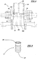
- Figure 4 shows a detail of the machine of Figure 1.
- Figure 5 is an enlarged perspective view of a container formed by the machine of Figure 1.
- Figure 6 is a schematic side view of a second embodiment of the invention.
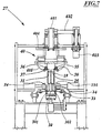
- Figures 7 and 8 are respectively an enlarged front view and an enlarged top plan view of elements of the machine of Figure 6.
- Figure 9 is a section through the element of Figure 8 on the plane IX-IX.
- Figure 10 is an enlarged view from above showing elements of the machine of Figure 6.
- Figure 11 is a side view of elements of Figure 10.
- Figure 12 is an exploded view of a portion of the container.
- the reference numeral 1 indicates the machine for forming a container of flexible material in web form 3 unwound from a reel 4.
- It comprises a pair of endless parallel chains 15 passing about intermittently driven sprockets 151, their links carrying a series of equidistant cylindrical supports 16.
- the supports 16 are individually supported by a parallelepiped base 30 fixed to the chain links.
- Each support 16 comprises an internally hollow tubular portion 28 provided with holes 29 along four generators at 90° apart and is connected to the underlying base via a groove 330 intended to contain a gasket 47 described hereinafter.
- the interior of the base 30 communicates with the outside via conduits 301 visible in Figure 7, to be connected to a pressurized gas supply.
- the transverse dimensions and height of the support 16 are slightly less than the corresponding transverse dimensions and height of the container 7, the portion 28 of the support 16 being of cylindrical or profiled shape.
- the base 30 consists of a profiled plate.
- the inner surface of each support 16 carries, at its free end portion, an abutment shoulder 31 (shown in Figure 12).
- the machine 1 comprises a station 2 for forming and cutting a tubular element 5 starting from the web wound on the reel 4.
- the means for folding the web into two, bonding it along a generator to form the tubular element 5, mounting the end of the tubular element 5 over the cylindrical support 16 lying in a horizontal position in front of the station 2, and cutting off a determined length of said tubular element which remains mounted over the support are not described or illustrated as they are of usual type, easily imaginable and designable by the average expert.
- the machine Immediately downstream of the station 2 the machine comprises a station 6 for closing the bottom of the tubular element to create the container 7.
- said means comprise a pair of heated bonding bars 211 and 212 supported respectively by a fixed support 210 and a movable support 21 driven by the cylinder-piston unit 213 via a lever 214 to be cyclically moved a distance from and close to the fixed support.
- the supports 16 Downstream of the station 6 the supports 16 pass below a series of profiled metal plates 22 which fold the ends of the bonded edge inwards towards each other until a presser element consisting of a profiled punch 23 causes said ends to adhere to the flat closed base of the container 7.
- a presser element consisting of a profiled punch 23 causes said ends to adhere to the flat closed base of the container 7.
- said punch compels the container base to partially retract into the container 7 to adhere to its walls.
- the machine comprises means 17 for forming a flange 18 at the open end of the container 7 facing the base 30.
- Said means comprise an annular abutment 33 axially slidable within a seat provided in each base 30 in the region adjacent to the tubular cylindrical portion 28.
- annular abutments 33 are forced against the open end of the container mounted over the support 16 by reciprocating linear actuators 32, shown schematically in Figure 1, to form a flange 18, shown in Figure 5 and intended to receive a flat closure element.
- counteracting means 34 are provided, each consisting of clamps disposed transverse to the conveyors 15, which retain the container 7.
- each container 7 undergoes a permanent deformation.
- Said shaping station 8 comprises a mould 12 comprising two facing shells 45 able to be spaced apart to allow entry of the support 16 with the relative container, and an upper closure member 46.
- Pneumatic means 13 are provided for feeding a pressurized gas into the support 16.
- the pneumatic means 13 consist of conduits 301 and 302 provided within the base 30 and connecting a source of compressed gas, such as a motor-driven air compressor, to the mould interior via the base 30.
- connection via said conduits is made by a pneumatic coupling which is connected automatically to them.
- the pneumatic means 13 comprise at least one shut-off valve, such as a solenoid valve.
- the supports 16 comprise, in proximity to the respective bases 30, a seat 330 for an annular gasket 47.
- the seat is connected to a source of compressed gas via the conduit 302.
- the gasket 47 expands by the effect of the compressed gas, for example the pressurized gas fed into the interior of the mould 12, to press the mouth portion of the container 7 against the corresponding region of the mould 12.
- the shaping station 8 also comprises means 50 ( Figure 3C) for heating the container 7 to a heating temperature of between 30°C and 60°C.
- the heating means consist, for example, of hot air blowing devices, or plates provided with electrical resistance elements, or infrared heaters.
- the mould 12 can comprise means for cooling the container 7 to a cooling temperature of between 30°C and 6°C.
- the cooling means 7 can comprise an open or closed circuit provided with conduits for circulating a cooling fluid, for example water, which extend within the walls of the pair of shells 45 and/or the member 46.
- the cooling means for the container 7 can also comprise a circulation pump and/or at least one solenoid valve, and adjustable temperature control devices for the fluid.
- the containers 7 When formed and shaped, the containers 7 are removed from the relative supports and transferred by expulsion means, such as compressed air blowers, to exit means 10, consisting for example of conveyor belts.
- expulsion means such as compressed air blowers
- the bonding station 6 comprises a positioning means 24, for example of the pick-and-place type, to position a base 25 against the inner shoulder 31 of the tubular portion 28 of the support 16.
- the base 25 for example circular or polygonal, is provided with a peripheral wall 26 perpendicular to the flat surface of the base.
- Clinching means 27 ( Figure 7) are provided to clinch the end of the wall of the tubular element 5 against the inner surface of the peripheral wall 26, and bonding means 41 for bonding the peripheral wall 26 to the wall of the tubular element 5 to form the base of the container 7.
- the clinching means 27 comprise two mutually facing cylindrical idle wheels 35, each provided with an annular lip 36. Each wheel is connected, via an articulated system ( Figures 10 and 11), to a unit 40 which causes it undergo rotation and translation.
- the unit 40 comprises an idle shaft 401 suspended from the machine frame and connected by a transmission 402 to an electric motor 403 for its rotation.
- the shaft supports a circular plate 404 on which two coplanar angular plates 405 slide, each carrying an articulated system 38.
- This latter comprises a crank, of which the arm 37c is rotatably received in the angle plate 405 and the arm 37b supports the pin 37a of the wheel 35.
- the arm 37b is rotatable about its axis relative to the crank arm, whereas the arm 37c can translate parallel to itself relative to the angle plate 405 ( Figure 11), being connected to this latter by slidable means 39d.
- crank The dimensions of the crank are such that the arm 37c is aligned with the diameter of the wheel 35.
- the articulated system 38 also comprises first elastic means 39a and second elastic means 39b intended to maintain the wheel 35 urged against the edge of the cylindrical support 16.
- Means are provided for translationally moving the angle plates 405 within their plane towards and away from the axis of rotation and for maintaining them equidistant from this latter.
- the symmetrical translation of the angle plates 405 causes the wheels 35 to approach each other until the respective annular lips 36 of the wheels 35 rest against the edge of the tubular element 5 at the free end of the support 16; rotating the unit 40 causes the wheels 35 to adhere along the entire path of the end of the support; the simultaneous movement of the wheels 35 towards the centre due to the progressive approach of the angle plates 405, in cooperation with the rotation, results in progressive clinching of the edge of the container along its interior.
- the tubular element 5 is disengaged from the wheels 35 by withdrawing these latter.
- the articulated system 38 enables the wheels 35 to translate towards the axis of rotation of the unit 40 while varying its orientation about the axis in order to maintain the lip 36 against the edge of the support element 16 and enable progressive clinching of the edge of the tubular element 5 against the end of the wall 26 of the base 25.
- the bonding means 41 each comprise at least one pair of bonding jaws 42 of approximately semi-cylindrical form insertable by insertion actuators 43 into those portions of the tubular element 5 which are to be bonded to the base 25, and divergeable by means of actuators 44.
- the pair of bonding jaws 42 of one bonding means 41 is perpendicular to the pair of bonding jaws of the other bonding means 41 to ensure continuity in the bonding of the base 25 to the container 7.
- the forming and cutting station 2 forms the tubular element 5, the chains 15 transfer the support means 16 to the bonding station 6 where the base of the container 7 is formed, then to the shaping station 8 in which the container is given a predetermined shape, and finally to the exit means 10 which convey them for example to storage devices or to filling and closure machines.
- the method for forming a container 7 starting from a reel of material in web form 3 comprises:
- the method also comprises folding the linearly bonded base by the effect of its interference with fixed guides 22 and pressing the folded base towards the interior of the container 7 before shaping its walls in the mould 12.
- the method comprises applying a base cover 25 close to the mouth of the tubular element 5, then folding the edge of the mouth against the cover 25 and finally bonding them together.
- the main advantage of the present invention is the provision of a method and machine for forming, starting from a reel of web material, containers formed into different shapes comprising curved surfaces.
- a further advantage of the present invention is the provision of a machine and method for forming containers from sheets of synthetic materials bonded to aluminium, paper and deformable crepe paper or from single-layer sheets.
- a further advantage is the provision of a machine which is of easy construction and maintenance, of high reliability, and economically advantageous.
Landscapes
- Engineering & Computer Science (AREA)
- Mechanical Engineering (AREA)
- Manufacturing & Machinery (AREA)
- Robotics (AREA)
- Making Paper Articles (AREA)
- Containers And Plastic Fillers For Packaging (AREA)
- Shaping Of Tube Ends By Bending Or Straightening (AREA)
- Auxiliary Devices For And Details Of Packaging Control (AREA)
- Package Closures (AREA)
- Basic Packing Technique (AREA)
- Replacement Of Web Rolls (AREA)
Abstract
Description
Claims (27)
- A method for forming a container 7 starting from a web (3) of heat-bondable material wound on a reel (4), characterised by comprising the following operations:forming a tubular element (5) of predetermined diameter and height;mounting the tubular element (5) over a support (16) for the tubular element (5);closing one end of the tubular element (5) to form the open container (7);inserting the container (7) into a mould (12) after heating if necessary;forcing the walls of the container (7) against the inner walls of the mould (12);opening the mould and withdrawing the container (7) from the support (16).
- A method as claimed in claim 1, characterised by also forming a flange (18) on the mouth of the container prior to its insertion into the mould.
- A method as claimed in claim 1, characterised in that said heating temperature is from 30°C to 60°C.
- A method as claimed in claim 1, characterised in that the pressure is between 3 and 30 bar.
- A method as claimed in claim 1, characterised in that after opening the mould the container is cooled to a temperature between 6° and 30°C.
- A method as claimed in claim 1, characterised in that the tubular element is closed by pinch-bonding.
- A method as claimed in claim 6, characterised in that after the pinch-bonding the base is folded back by interference with fixed guides (22) and pressed towards the interior of the container (7).
- A method as claimed in claim 1, characterised in that the tubular element is closed by applying a flat cover (25) into the mouth of the tubular element (5), and then bonding the base.
- A method as claimed in claim 8, characterised in that before bonding the base, the mouth edge abutting the cover (25) is clinched onto the cover.
- A method as claimed in claim 1, characterised in that within the mould the container undergoes permanent deformation both in the axial direction and in the longitudinal direction.
- A machine for forming a container (7) of flexible material starting from web wound on a reel, characterised by comprising an endless conveyor provided with equidistant cylindrical supports (16) and driven intermittently to bring each of said supports in succession in front of:a station (2) for forming and cutting a tubular element (5) from said web unwound from the reel (4);a station (6) for closing one end of the tubular element (5), to obtain an open container (7);a shaping station (8) provided with a mould (12) comprising a plurality of elements (45, 46);pneumatic means (13) for feeding gas under pressure into the container (7) contained in the mould;means for discharging the shaped container from the cylindrical support after opening the mould.
- A machine as claimed in claim 11, characterised in that the shaping station (8) also comprises means (50) for heating the container (7) to a heating temperature between 30° and 60°C.
- A machine as claimed in claim 11, characterised in that the mould (12) also comprises means for cooling the container (7) to a cooling temperature between 6° and 30°C.
- A machine as claimed in claim 11, characterised in that the conveyor is a chain conveyor.
- A machine as claimed in claim 11, characterised in that each support (16) presents a base (39) fixed to the conveyor (15) and a tubular means (28) comprising a plurality of apertures (29) passing through its wall, said support (16) having dimensions less than those of the container (7).
- A machine as claimed in claim 15, characterised in that the inner surface of each support (16) carries, on its free end portion, an abutment shoulder (31).
- A machine as claimed in claim 14, characterised in that the annular conveyor (15) consists of a reinforced belt.
- A machine as claimed in claim 11, characterised by comprising means (17) for forming a flange (18) on one end of the tubular element (5).
- A machine as claimed in claim 18, characterised in that said means comprise annular abutments (33) axially slidable within a seat therefor provided in each base (30) in proximity to the relative tubular portion (28) and driven by reciprocating linear actuators (32) to force the annular abutments (33) against the end of the relative tubular element (5) or container (7), and stop means (34) therefor.
- A machine as claimed in claim 11, characterised in that the closure station (6) comprises a pinch bonder (21) which linearly bonds the end portion of the tubular element (5).
- A machine as claimed in claim 20, characterised in that the closure station (6) comprises a plurality of guides (22) for folding the bonded portion towards the base of the container (7) and punch means (23) which press the bonded and folded portion to cause it to adhere to the base of the container (7).
- A machine as claimed in claim 11 and claim 16, characterised in that the closure station (6) comprises a means (24) to position against the shoulder (31) a base (25) provided with a relative peripheral wall (26); clinching means (27) for clinching the end of the wall of the tubular element (5) against the inner surface of the peripheral wall (26); and bonding means (41) for bonding the peripheral wall (26) to the wall of the tubular element (5) to form the base of the container (7).
- A machine as claimed in claim 22, characterised in that the clinching means (27) comprise at least one idle wheel (35) provided with an annular lip (36) and connected via a relative articulated system (38) to a rotation and translation inducing means (40).
- A machine as claimed in claim 23, characterised in that said articulated system (38) comprises a pin (37a) of the idle wheel (35) connected by a joint (37b) to a shaft (37c) orientated perpendicular to the pin (37a) towards the centre of the wheel (35) and rotatably associated with slidable means (37d) orientated towards the conveyor (15) and having one end fixed to the rotation and translation means (40); said articulated system comprising first elastic means (39a) and second elastic means (39b) intended to maintain the wheel (35) in contact with the edge of the cylindrical support (16).
- A machine as claimed in claim 22, characterised in that the bonding means (41) comprise at least one pair of bonding jaws (42) of approximately semi-cylindrical form insertable by insertion actuators (43) into those portions of the tubular element (5) and base (25) which are to be bonded together, and divergeable by means of diverger actuators (44) to press against and bond together these latter portions.
- A machine as claimed in claim 25, characterised by comprising two pairs of mutually offset bonding jaws.
- A machine as claimed in claim 11, characterised in that the supports (16) comprise, for an annular gasket (47), a seat connected to a source of compressed gas, said annular gasket (47) being intended to expand under the action of the compressed gas.
Applications Claiming Priority (2)
| Application Number | Priority Date | Filing Date | Title |
|---|---|---|---|
| IT2000BO000543A ITBO20000543A1 (en) | 2000-09-19 | 2000-09-19 | MACHINE AND METHOD FOR FORMING A CONTAINER STARTING FROM A BAND OF TAPE MATERIAL |
| ITBO000543 | 2000-09-19 |
Publications (3)
| Publication Number | Publication Date |
|---|---|
| EP1188542A2 true EP1188542A2 (en) | 2002-03-20 |
| EP1188542A3 EP1188542A3 (en) | 2003-11-26 |
| EP1188542B1 EP1188542B1 (en) | 2006-01-18 |
Family
ID=11438733
Family Applications (1)
| Application Number | Title | Priority Date | Filing Date |
|---|---|---|---|
| EP01201552A Expired - Lifetime EP1188542B1 (en) | 2000-09-19 | 2001-04-25 | Machine and method for forming a container starting from a reel of material in web form |
Country Status (6)
| Country | Link |
|---|---|
| US (1) | US6723196B2 (en) |
| EP (1) | EP1188542B1 (en) |
| AT (1) | ATE315992T1 (en) |
| DE (1) | DE60116707T2 (en) |
| ES (1) | ES2254315T3 (en) |
| IT (1) | ITBO20000543A1 (en) |
Cited By (4)
| Publication number | Priority date | Publication date | Assignee | Title |
|---|---|---|---|---|
| EP1422053A1 (en) * | 2002-11-20 | 2004-05-26 | Luigi Fioretti | Device for fitting a tubular element on a support of a complementary cross section and for defining a bottom of the tubular element |
| CN101961916A (en) * | 2010-10-21 | 2011-02-02 | 张士生 | Suspension type bottle blank tube elastic connector |
| EP2942188A2 (en) | 2014-05-06 | 2015-11-11 | Societa' per Azioni Curti - Costruzioni Meccaniche | A method and a machine for manufacturing containers |
| CN116985392A (en) * | 2023-07-13 | 2023-11-03 | 山东冠通管业有限公司 | Full-automatic flanging device for glass fiber reinforced plastic composite pipe |
Families Citing this family (4)
| Publication number | Priority date | Publication date | Assignee | Title |
|---|---|---|---|---|
| RU2657693C2 (en) * | 2014-01-29 | 2018-06-14 | Футура С.П.А. | Cardboard tubes manufacturing equipment and method |
| MX385019B (en) | 2014-02-24 | 2025-03-04 | Pregis Innovative Packaging Llc | INFLATABLE FILM HANDLING DEVICE. |
| CN111873261B (en) * | 2020-07-09 | 2022-06-24 | 董燕 | Skin loading attachment is used in processing of shower bathtub |
| CN116653274B (en) * | 2023-06-28 | 2025-07-15 | 中山市睿硕智能科技有限公司 | Necking equipment |
Family Cites Families (9)
| Publication number | Priority date | Publication date | Assignee | Title |
|---|---|---|---|---|
| US3217071A (en) * | 1961-12-13 | 1965-11-09 | Owens Illinois Glass Co | Method of forming hollow plastic articles |
| FR1403746A (en) * | 1964-05-12 | 1965-06-25 | Flexible tube for containing liquids, pastes or other products and method of manufacture | |
| US3505705A (en) * | 1966-12-28 | 1970-04-14 | Total Packaging Inc | Apparatus for production and filling of flangeless plastic containers |
| DE1679904B2 (en) * | 1967-09-30 | 1975-05-07 | C.F. Spiess & Sohn, 6719 Kleinkarlbach | Method and device for the production of thin-walled packaging containers, open on one side, made of thermoplastic material |
| JPS56123838A (en) * | 1980-03-06 | 1981-09-29 | Sumitomo Bakelite Co Ltd | Method and apparatus for bottom mounting for cylindrical container |
| US4366016A (en) * | 1981-06-25 | 1982-12-28 | Owens-Illinois, Inc. | Method and apparatus for producing a plastic sleeve |
| US4436569A (en) * | 1981-09-21 | 1984-03-13 | The United States Of America As Represented By The Secretary Of The Navy | Method for forming a protective cover for aircraft having conical radomes |
| US4796766A (en) * | 1982-04-01 | 1989-01-10 | The Continental Group, Inc. | Plastic container and method of forming same |
| US6866905B1 (en) * | 1998-11-30 | 2005-03-15 | Fort James Corporation | Injection blow-molded disposable tumbler and method of making same |
-
2000
- 2000-09-19 IT IT2000BO000543A patent/ITBO20000543A1/en unknown
-
2001
- 2001-04-25 DE DE60116707T patent/DE60116707T2/en not_active Expired - Lifetime
- 2001-04-25 ES ES01201552T patent/ES2254315T3/en not_active Expired - Lifetime
- 2001-04-25 AT AT01201552T patent/ATE315992T1/en not_active IP Right Cessation
- 2001-04-25 EP EP01201552A patent/EP1188542B1/en not_active Expired - Lifetime
- 2001-05-30 US US09/866,795 patent/US6723196B2/en not_active Expired - Lifetime
Cited By (7)
| Publication number | Priority date | Publication date | Assignee | Title |
|---|---|---|---|---|
| EP1422053A1 (en) * | 2002-11-20 | 2004-05-26 | Luigi Fioretti | Device for fitting a tubular element on a support of a complementary cross section and for defining a bottom of the tubular element |
| CN101961916A (en) * | 2010-10-21 | 2011-02-02 | 张士生 | Suspension type bottle blank tube elastic connector |
| EP2942188A2 (en) | 2014-05-06 | 2015-11-11 | Societa' per Azioni Curti - Costruzioni Meccaniche | A method and a machine for manufacturing containers |
| EP2942188A3 (en) * | 2014-05-06 | 2016-01-20 | Societa' per Azioni Curti - Costruzioni Meccaniche | A method and a machine for manufacturing containers |
| EP3446866A1 (en) | 2014-05-06 | 2019-02-27 | Societa' per Azioni Curti - Costruzioni Meccaniche | A method and a machine for manufacturing containers |
| US10272617B2 (en) | 2014-05-06 | 2019-04-30 | Societa' Per Azioni Curti-Costruzoni Meccaniche | Method and a machine for manufacturing containers |
| CN116985392A (en) * | 2023-07-13 | 2023-11-03 | 山东冠通管业有限公司 | Full-automatic flanging device for glass fiber reinforced plastic composite pipe |
Also Published As
| Publication number | Publication date |
|---|---|
| EP1188542A3 (en) | 2003-11-26 |
| ITBO20000543A1 (en) | 2002-03-19 |
| EP1188542B1 (en) | 2006-01-18 |
| DE60116707T2 (en) | 2006-08-10 |
| ATE315992T1 (en) | 2006-02-15 |
| ES2254315T3 (en) | 2006-06-16 |
| US6723196B2 (en) | 2004-04-20 |
| DE60116707D1 (en) | 2006-04-06 |
| US20020035022A1 (en) | 2002-03-21 |
| ITBO20000543A0 (en) | 2000-09-19 |
Similar Documents
| Publication | Publication Date | Title |
|---|---|---|
| AU620601B2 (en) | Reclosable bag | |
| EP2248723B1 (en) | A sytem for packaging products in stick packs | |
| US6070395A (en) | Method for joint packaging of bags and their contents and machine for performing such method | |
| CZ279925B6 (en) | Forming device for packaging machines | |
| EP1481899B1 (en) | Machine for manufacturing, filling and closing mesh bags from a continuous roll of tubular mesh | |
| KR20130140109A (en) | Device for vacuum packaging, particularly of food products | |
| EP1188542B1 (en) | Machine and method for forming a container starting from a reel of material in web form | |
| US6722104B1 (en) | Method and packaging machine for forming a container, a blank web and a filled container | |
| ES2462666T3 (en) | Vertical packaging system and method | |
| EP1631495B1 (en) | Method of producing packaging containers from plastics and a packaging machine | |
| US4646507A (en) | Machine for making packs for flowing material | |
| US20030127151A1 (en) | Apparatus and process for manufacturing a filled flexible pouch | |
| TW208688B (en) | ||
| JPH06296452A (en) | Method for continuous packaging of article in form of paste, semifluid or liquid | |
| RU2321495C2 (en) | Container forming system, especially, containers for food products | |
| CN105082548B (en) | The method and machine of manufacture container | |
| US4670279A (en) | Method for wrapping essentially flat products of the luxury-item or foodstuffs industry, especially squares or bars of chocolate, in packaging foil | |
| EP1074471B1 (en) | Machine for the fabrication of containers with consumable content | |
| US11840364B2 (en) | Packaging machine for packaging portioned products which are liquid or pasty in the processing state | |
| JP2535959B2 (en) | Liquid filling and sealing device with spout attachment device | |
| JP2002515365A (en) | Container forming device | |
| JP2002515366A (en) | Blank supply method and apparatus | |
| JPH0718564Y2 (en) | Container molding and filling device | |
| JPH0138654B2 (en) | ||
| US20030040410A1 (en) | Method and device for a packaging machine |
Legal Events
| Date | Code | Title | Description |
|---|---|---|---|
| PUAI | Public reference made under article 153(3) epc to a published international application that has entered the european phase |
Free format text: ORIGINAL CODE: 0009012 |
|
| AK | Designated contracting states |
Kind code of ref document: A2 Designated state(s): AT BE CH CY DE DK ES FI FR GB GR IE IT LI LU MC NL PT SE TR |
|
| AX | Request for extension of the european patent |
Free format text: AL;LT;LV;MK;RO;SI |
|
| PUAL | Search report despatched |
Free format text: ORIGINAL CODE: 0009013 |
|
| AK | Designated contracting states |
Kind code of ref document: A3 Designated state(s): AT BE CH CY DE DK ES FI FR GB GR IE IT LI LU MC NL PT SE TR |
|
| AX | Request for extension of the european patent |
Extension state: AL LT LV MK RO SI |
|
| 17P | Request for examination filed |
Effective date: 20040503 |
|
| AKX | Designation fees paid |
Designated state(s): AT BE CH CY DE DK ES FI FR GB GR IE IT LI LU MC NL PT SE TR |
|
| AXX | Extension fees paid |
Extension state: SI Payment date: 20040503 |
|
| 17Q | First examination report despatched |
Effective date: 20040730 |
|
| GRAP | Despatch of communication of intention to grant a patent |
Free format text: ORIGINAL CODE: EPIDOSNIGR1 |
|
| GRAS | Grant fee paid |
Free format text: ORIGINAL CODE: EPIDOSNIGR3 |
|
| GRAA | (expected) grant |
Free format text: ORIGINAL CODE: 0009210 |
|
| AK | Designated contracting states |
Kind code of ref document: B1 Designated state(s): AT BE CH CY DE DK ES FI FR GB GR IE IT LI LU MC NL PT SE TR |
|
| AX | Request for extension of the european patent |
Extension state: SI |
|
| PG25 | Lapsed in a contracting state [announced via postgrant information from national office to epo] |
Ref country code: FI Free format text: LAPSE BECAUSE OF FAILURE TO SUBMIT A TRANSLATION OF THE DESCRIPTION OR TO PAY THE FEE WITHIN THE PRESCRIBED TIME-LIMIT Effective date: 20060118 Ref country code: BE Free format text: LAPSE BECAUSE OF FAILURE TO SUBMIT A TRANSLATION OF THE DESCRIPTION OR TO PAY THE FEE WITHIN THE PRESCRIBED TIME-LIMIT Effective date: 20060118 Ref country code: AT Free format text: LAPSE BECAUSE OF FAILURE TO SUBMIT A TRANSLATION OF THE DESCRIPTION OR TO PAY THE FEE WITHIN THE PRESCRIBED TIME-LIMIT Effective date: 20060118 |
|
| REG | Reference to a national code |
Ref country code: GB Ref legal event code: FG4D |
|
| REG | Reference to a national code |
Ref country code: CH Ref legal event code: EP |
|
| REG | Reference to a national code |
Ref country code: CH Ref legal event code: NV Representative=s name: ISLER & PEDRAZZINI AG |
|
| REG | Reference to a national code |
Ref country code: IE Ref legal event code: FG4D |
|
| REF | Corresponds to: |
Ref document number: 60116707 Country of ref document: DE Date of ref document: 20060406 Kind code of ref document: P |
|
| PG25 | Lapsed in a contracting state [announced via postgrant information from national office to epo] |
Ref country code: DK Free format text: LAPSE BECAUSE OF FAILURE TO SUBMIT A TRANSLATION OF THE DESCRIPTION OR TO PAY THE FEE WITHIN THE PRESCRIBED TIME-LIMIT Effective date: 20060418 |
|
| REG | Reference to a national code |
Ref country code: SE Ref legal event code: TRGR |
|
| PG25 | Lapsed in a contracting state [announced via postgrant information from national office to epo] |
Ref country code: IE Free format text: LAPSE BECAUSE OF NON-PAYMENT OF DUE FEES Effective date: 20060425 |
|
| PG25 | Lapsed in a contracting state [announced via postgrant information from national office to epo] |
Ref country code: MC Free format text: LAPSE BECAUSE OF NON-PAYMENT OF DUE FEES Effective date: 20060430 |
|
| REG | Reference to a national code |
Ref country code: ES Ref legal event code: FG2A Ref document number: 2254315 Country of ref document: ES Kind code of ref document: T3 |
|
| PG25 | Lapsed in a contracting state [announced via postgrant information from national office to epo] |
Ref country code: PT Free format text: LAPSE BECAUSE OF FAILURE TO SUBMIT A TRANSLATION OF THE DESCRIPTION OR TO PAY THE FEE WITHIN THE PRESCRIBED TIME-LIMIT Effective date: 20060619 |
|
| ET | Fr: translation filed | ||
| PLBE | No opposition filed within time limit |
Free format text: ORIGINAL CODE: 0009261 |
|
| STAA | Information on the status of an ep patent application or granted ep patent |
Free format text: STATUS: NO OPPOSITION FILED WITHIN TIME LIMIT |
|
| 26N | No opposition filed |
Effective date: 20061019 |
|
| REG | Reference to a national code |
Ref country code: CH Ref legal event code: PCAR Free format text: ISLER & PEDRAZZINI AG;POSTFACH 1772;8027 ZUERICH (CH) |
|
| PG25 | Lapsed in a contracting state [announced via postgrant information from national office to epo] |
Ref country code: GR Free format text: LAPSE BECAUSE OF FAILURE TO SUBMIT A TRANSLATION OF THE DESCRIPTION OR TO PAY THE FEE WITHIN THE PRESCRIBED TIME-LIMIT Effective date: 20060419 |
|
| PG25 | Lapsed in a contracting state [announced via postgrant information from national office to epo] |
Ref country code: LU Free format text: LAPSE BECAUSE OF NON-PAYMENT OF DUE FEES Effective date: 20060425 Ref country code: TR Free format text: LAPSE BECAUSE OF FAILURE TO SUBMIT A TRANSLATION OF THE DESCRIPTION OR TO PAY THE FEE WITHIN THE PRESCRIBED TIME-LIMIT Effective date: 20060118 |
|
| PG25 | Lapsed in a contracting state [announced via postgrant information from national office to epo] |
Ref country code: CY Free format text: LAPSE BECAUSE OF FAILURE TO SUBMIT A TRANSLATION OF THE DESCRIPTION OR TO PAY THE FEE WITHIN THE PRESCRIBED TIME-LIMIT Effective date: 20060118 |
|
| REG | Reference to a national code |
Ref country code: FR Ref legal event code: PLFP Year of fee payment: 16 |
|
| PGFP | Annual fee paid to national office [announced via postgrant information from national office to epo] |
Ref country code: NL Payment date: 20160426 Year of fee payment: 16 |
|
| PGFP | Annual fee paid to national office [announced via postgrant information from national office to epo] |
Ref country code: DE Payment date: 20160427 Year of fee payment: 16 Ref country code: CH Payment date: 20160427 Year of fee payment: 16 Ref country code: GB Payment date: 20160427 Year of fee payment: 16 Ref country code: ES Payment date: 20160426 Year of fee payment: 16 |
|
| PGFP | Annual fee paid to national office [announced via postgrant information from national office to epo] |
Ref country code: IT Payment date: 20160427 Year of fee payment: 16 Ref country code: FR Payment date: 20160425 Year of fee payment: 16 Ref country code: SE Payment date: 20160427 Year of fee payment: 16 |
|
| REG | Reference to a national code |
Ref country code: DE Ref legal event code: R119 Ref document number: 60116707 Country of ref document: DE |
|
| REG | Reference to a national code |
Ref country code: CH Ref legal event code: PL |
|
| REG | Reference to a national code |
Ref country code: NL Ref legal event code: MM Effective date: 20170501 |
|
| GBPC | Gb: european patent ceased through non-payment of renewal fee |
Effective date: 20170425 |
|
| REG | Reference to a national code |
Ref country code: FR Ref legal event code: ST Effective date: 20171229 |
|
| PG25 | Lapsed in a contracting state [announced via postgrant information from national office to epo] |
Ref country code: NL Free format text: LAPSE BECAUSE OF NON-PAYMENT OF DUE FEES Effective date: 20170501 Ref country code: FR Free format text: LAPSE BECAUSE OF NON-PAYMENT OF DUE FEES Effective date: 20170502 Ref country code: DE Free format text: LAPSE BECAUSE OF NON-PAYMENT OF DUE FEES Effective date: 20171103 |
|
| PG25 | Lapsed in a contracting state [announced via postgrant information from national office to epo] |
Ref country code: LI Free format text: LAPSE BECAUSE OF NON-PAYMENT OF DUE FEES Effective date: 20170430 Ref country code: GB Free format text: LAPSE BECAUSE OF NON-PAYMENT OF DUE FEES Effective date: 20170425 Ref country code: CH Free format text: LAPSE BECAUSE OF NON-PAYMENT OF DUE FEES Effective date: 20170430 Ref country code: SE Free format text: LAPSE BECAUSE OF NON-PAYMENT OF DUE FEES Effective date: 20170426 |
|
| PG25 | Lapsed in a contracting state [announced via postgrant information from national office to epo] |
Ref country code: IT Free format text: LAPSE BECAUSE OF NON-PAYMENT OF DUE FEES Effective date: 20170425 |
|
| REG | Reference to a national code |
Ref country code: ES Ref legal event code: FD2A Effective date: 20180704 |
|
| PG25 | Lapsed in a contracting state [announced via postgrant information from national office to epo] |
Ref country code: ES Free format text: LAPSE BECAUSE OF NON-PAYMENT OF DUE FEES Effective date: 20170426 |