EP1188405A2 - Vacuum cleaner with improved cooling - Google Patents
Vacuum cleaner with improved cooling Download PDFInfo
- Publication number
- EP1188405A2 EP1188405A2 EP01402061A EP01402061A EP1188405A2 EP 1188405 A2 EP1188405 A2 EP 1188405A2 EP 01402061 A EP01402061 A EP 01402061A EP 01402061 A EP01402061 A EP 01402061A EP 1188405 A2 EP1188405 A2 EP 1188405A2
- Authority
- EP
- European Patent Office
- Prior art keywords
- chamber
- cord
- air
- vacuum cleaner
- case
- Prior art date
- Legal status (The legal status is an assumption and is not a legal conclusion. Google has not performed a legal analysis and makes no representation as to the accuracy of the status listed.)
- Withdrawn
Links
- 238000001816 cooling Methods 0.000 title description 19
- 239000000428 dust Substances 0.000 claims abstract description 77
- 238000007599 discharging Methods 0.000 claims abstract description 15
- 238000001914 filtration Methods 0.000 claims abstract description 9
- 238000005192 partition Methods 0.000 claims description 7
- 230000002093 peripheral effect Effects 0.000 claims description 7
- 230000002745 absorbent Effects 0.000 claims description 3
- 239000002250 absorbent Substances 0.000 claims description 3
- 238000013021 overheating Methods 0.000 abstract description 3
- 239000000463 material Substances 0.000 description 9
- 238000004891 communication Methods 0.000 description 2
- 238000010438 heat treatment Methods 0.000 description 2
- 238000000034 method Methods 0.000 description 2
- 238000004804 winding Methods 0.000 description 2
- 238000013459 approach Methods 0.000 description 1
- 238000004140 cleaning Methods 0.000 description 1
- 239000011248 coating agent Substances 0.000 description 1
- 238000013461 design Methods 0.000 description 1
- -1 dirt Substances 0.000 description 1
- 238000002474 experimental method Methods 0.000 description 1
- 239000006260 foam Substances 0.000 description 1
- 230000020169 heat generation Effects 0.000 description 1
- 238000004519 manufacturing process Methods 0.000 description 1
- 238000012986 modification Methods 0.000 description 1
- 230000004048 modification Effects 0.000 description 1
- 230000000630 rising effect Effects 0.000 description 1
- 229920003002 synthetic resin Polymers 0.000 description 1
- 239000000057 synthetic resin Substances 0.000 description 1
Images




Classifications
-
- A—HUMAN NECESSITIES
- A47—FURNITURE; DOMESTIC ARTICLES OR APPLIANCES; COFFEE MILLS; SPICE MILLS; SUCTION CLEANERS IN GENERAL
- A47L—DOMESTIC WASHING OR CLEANING; SUCTION CLEANERS IN GENERAL
- A47L9/00—Details or accessories of suction cleaners, e.g. mechanical means for controlling the suction or for effecting pulsating action; Storing devices specially adapted to suction cleaners or parts thereof; Carrying-vehicles specially adapted for suction cleaners
- A47L9/22—Mountings for motor fan assemblies
-
- A—HUMAN NECESSITIES
- A47—FURNITURE; DOMESTIC ARTICLES OR APPLIANCES; COFFEE MILLS; SPICE MILLS; SUCTION CLEANERS IN GENERAL
- A47L—DOMESTIC WASHING OR CLEANING; SUCTION CLEANERS IN GENERAL
- A47L9/00—Details or accessories of suction cleaners, e.g. mechanical means for controlling the suction or for effecting pulsating action; Storing devices specially adapted to suction cleaners or parts thereof; Carrying-vehicles specially adapted for suction cleaners
-
- A—HUMAN NECESSITIES
- A47—FURNITURE; DOMESTIC ARTICLES OR APPLIANCES; COFFEE MILLS; SPICE MILLS; SUCTION CLEANERS IN GENERAL
- A47L—DOMESTIC WASHING OR CLEANING; SUCTION CLEANERS IN GENERAL
- A47L9/00—Details or accessories of suction cleaners, e.g. mechanical means for controlling the suction or for effecting pulsating action; Storing devices specially adapted to suction cleaners or parts thereof; Carrying-vehicles specially adapted for suction cleaners
- A47L9/26—Incorporation of winding devices for electric cables
Definitions
- the present invention relates to a vacuum cleaner, and particularly, to a vacuum cleaner in which an appliance chamber forming a suction force and a cord chamber for storing and winding an electrical cord are included.
- a vacuum cleaner is an appliance for removing foreign materials such as dirt, dust and debris using a strong suction force generated by operation of a fan motor assembly.
- a conventional vacuum cleaner as shown in Figure 1, includes a case 10 in which a suction head 1, an extension tube 3, and a suction hose 5 are connected in series so as to suck up the foreign materials such as dust therethrough.
- a dust chamber 12 including a dust bag 20 for collecting the foreign materials such as dust included in the sucked air is disposed at the inner front side of the case 10, and an appliance chamber 13 generating suction force and a cord chamber 14 for storing a wound electrical cord are disposed to the rear of the dust chamber 12 parting inside the case.
- a suction port 15 communicating with the dust chamber 12 is formed in a front part of the appliance chamber 13, a fan motor assembly 30 for generating the suction force is installed to the rear of the suction port 15, and a discharge port 16 for discharging therethrough the sucked air to the outside of the case 10 is installed at the rear side of the fan motor assembly 30.
- an exhaust filter 17 is installed at the discharge port 16.
- a cord reel 42 for winding the electrical cord 41 is installed in the cord chamber 14, and the cord reel 42 is rotated on a reel axle shaft 40 supported inside of the case 10.
- Figure 2 is a side cross-sectional view taken along line A-A in Figure 1, and showing the internal structure of the appliance chamber
- Figure 3 is an exploded perspective view showing the fan motor assembly installed in the appliance chamber shown in Figure 2.
- the fan motor assembly 30 installed in the appliance chamber 13 includes a driving motor 31 having a rotating shaft 32; a centrifugal fan 34 installed on the rotating shaft 32 of the driving motor 31; a guide vane wheel 35 installed between the driving motor 31 and the centrifugal fan 34 and guiding the air discharged from the centrifugal fan 34 to the driving motor 31 through a plurality of vanes 35a and an opening hole 35b in the central part thereof; and a fan cover 36, in which the centrifugal fan 34 and the guide vane 35 are enclosed, communicating with the suction port 15 communicated with the dust chamber 12.
- a motor housing 33 including a stator and a rotor is installed in the driving motor 31, and an inlet port 33a for introducing the air discharged through the opening hole 35b of the guide vane 35 is disposed in a front side of the motor housing 33.
- an exhaust port 33b for discharging the air sucked inside the housing 33 to the appliance chamber 13 is formed in a peripheral surface of the housing 33.
- the peripheral surface of the motor housing 33 is covered by an acoustically absorbent sleeve 38 made of a multiperforated film, whereby the outside of the exhaust hole 33b is covered, and at the same time, the noise generated when the air is discharged from the motor housing 33 is reduced.
- Figure 4 is a side cross-sectional view taken along line B-B in Figure 1, showing the inner structure of the cord chamber, and Figure 5 is a plan view showing the cord reel installed in the cord chamber in Figure 4.
- a cord passage hole 19 is formed in the cord chamber 14 on rear side of the case 10 so that the electrical cord can be drawn therethrough, and the cord reel 42 including a hub 43 and reel flanges 44 is installed inside the cord chamber 14 so that the electrical cord 41 can be wound thereonto.
- the cord reel 42 is installed to be rotational on the reel axle shaft 40 so that the electrical cord 41 is able to be wound or unwound.
- heat is generated in the electrical cord 41 while operating the vacuum cleaner, and especially, as vacuum cleaners having strong suction force using motors of high-efficiency and high-energy are developed, more heat is generated in the electrical cord 41.
- the electrical cord 41 must be wound more densely on the cord reel 42 and smaller gauge cords may be adopted, whereby the heating value per unit volume is increased, and accordingly, the temperature of the electrical cord 41 approaches to the safety threshold level.
- a plurality of cooling holes 43a and 44a through which the air passes are formed in the cord reel 42 so that the electrical cord 41 may be cooled through heat exchange with the air flowing thereover and therethrough smoothly, as shown in Figure 7.
- the conventional vacuum cleaner having the structure including the appliance chamber 13 and the cord chamber 14 as described above is operated as follows.
- the driving motor 31 When the electric current is applied to the vacuum cleaner, the driving motor 31 is operated, and the centrifugal fan 34 inside the appliance chamber 13 rotates, whereby foreign materials such as dust are sucked with the air into the dust bag 20 through the suction head 1 and suction hose 5 by the suction force of sucking the air inside the dust chamber 12.
- the air sucked inside the dust bag 20 flows toward the appliance chamber 30 by the continuing suction operation of the fan motor assembly. At that time, the foreign materials such as dust included in the air are left inside the dust bag 20 by filtering, and the air passing through the dust bag 20 is sucked into the appliance chamber 30, and after that, the air is discharged outside of the vacuum cleaner through the discharge port 16 in the case 10.
- the flowing process of the air inside the appliance chamber 30 will now be described.
- the air sucked through the suction port 15 between the dust chamber 12 and the appliance chamber 13 enters into the centrifugal fan 34 through the suction port 36a in the fan cover 36.
- the air passed through the centrifugal fan 34 flows toward the center from the peripheral surfaces of the guide vanes 35, and after that the air is sucked into the motor housing 33 through the opening hole 35b in the center of the guide vane 35.
- the air entering into the motor housing 33 cools down the motor parts such as the stator and the rotor, and after that, the air is discharged into the inside of the case through the exhaust port 33b in the motor housing 33. Then, the air is discharged to the outside through the exhaust filter 17 and through the discharge port 16 of the case 10, as long as the vacuum cleaner is operated.
- the conventional vacuum cleaner described above has problems, such that the air heated while going through the fan motor assembly 30 is discharged directly to the appliance chamber 13 through the exhaust port 33b, after that, the air is discharged outside the case 10. Therefore, the case 10 may be distorted by the heated air discharged from the fan motor assembly 30.
- the air entering into the fan motor assembly 30 from the appliance chamber 12 is heated while going through the centrifugal fan 34 rotating at high speed and being compressed, and it is heated again inside the driving motor 31, and accordingly the temperature of the air discharged from the fan motor assembly 30 is very high.
- the case 10 forming the appliance chamber 13 is generally made using a synthetic resin material, and therefore the high temperature air discharged from the fan motor assembly 30 directly contacts the case 10 , and the case 10 may be distorted by the high temperature air if the cleaner is used for a lone time.
- the cord chamber 14 in which the electrical cord 41 is wound and stored has a closed structure except for the cord pass hole 19 for passing the electrical cord 41, and thereby the temperature in the cord chamber 14 is risen in accordance with the heat generation in the electrical cord 41.
- the heat generated from the electrical cord 41 while using the vacuum cleaner flows to upper part of the cord chamber 14, and remains therein, whereby the gap in the temperature between the upper part and lower part of the cord chamber 14 is about 26°C.
- the temperatures of the electrical cord 41 and of the cord chamber 14 become nearly same, and the electrical cord 41 is not cooled down well even if the cooling holes 43a and 43b are formed in the cord reel 43.
- an object of the present invention is to provide a vacuum cleaner provided with a flowing guide for passing high temperature air installed between a fan motor assembly and a discharge port, and also with a flowing passage for cooling installed between a dust chamber and cord chamber, whereby overheating of the case and electrical cord may be prevented, and whereby the durability and reliability of the vacuum cleaner are enhanced.
- a vacuum cleaner which includes a case having a dust chamber for filtering dust from sucked-in air, an appliance chamber sucking the filtered air from the dust chamber and discharging it outside through a discharge port, and a cord chamber for storing a wound electrical cord, these chambers being separated from one another; a fan motor assembly installed inside the appliance chamber of the case for forcedly sucking in and discharging air into the inside of the dust chamber; an exhaust duct means installed between the fan motor assembly and the exhaust port in the case and guiding the air discharged through the fan motor assembly to the exhaust port; and a flowing passage means disposed between the dust chamber and the cord chamber so that the air is able to flow inside the cord chamber.
- a vacuum cleaner which includes a case in which are installed a dust chamber for filtering dust included in sucked-in air, and an appliance chamber sucking the filtered air in the dust chamber and discharging the air outside the case through a discharge port; a fan motor assembly installed inside the appliance chamber in the case and forcedly sucking and discharging the air inside the dust chamber; and a discharge duct installed between the fan motor assembly and the discharge port in the case and guiding the air discharged through the fan motor assembly to the discharge port.
- a vacuum cleaner which includes a case in which a dust chamber for filtering dust included in sucked-in air, and a cord chamber having a cord pass in hole in one side and storing a wound electrical cord are installed separated from each other; and at least one flowing passage is provided between the dust chamber and the cord chamber so that air is able to flow therebetween.
- Figure 8 is a transverse cross-sectional view illustrating a vacuum cleaner in accordance with the present invention.
- the vacuum cleaner according to the present invention includes a suction head 51, an extension tube 52, and a suction hose 53 connected with each other and coupled to a front side of the case 55 so as to suck dust thereinto.
- the case 55 includes a dust chamber 56 having a dust bag 60 for filtering dust included in sucked-in air, an appliance chamber 57 sucking the filtered air in the dust chamber 56 and discharging it outside through a discharge port 57b, and a cord chamber 58 storing a wound electrical cord 81, these chamber 56, 57 and 58 being separated by respective parting walls 55a, 55b and 55c.
- the dust chamber 56 is located in the front portion of the case 55, and the appliance chamber 57 and the cord chamber 58 are disposed in the rear portion of the case 55 behind the dust chamber 56 and separated by the partition wall 55c.
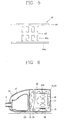
- Figure 9 is a side cross-sectional view taken along the line C-C in Figure 8 showing the inner structure of the appliance chamber 57.
- a suction port 57a communicated to the dust chamber 56 is formed in the partition wall 55a in the front of the appliance chamber 57.
- the fan motor assembly 70 is installed at the rear side of the suction port 57a for generating a suction force therethrough, and the discharge port 57b is installed at the rear side of the fan motor assembly 70 so that the sucked-in air is able to be discharged therethrough outside the case 55.
- the fan motor assembly 70 includes a driving motor (not shown) and a centrifugal fan (not shown) so as to forcedly suck the air from inside the dust chamber 56 and discharge the air as described above.
- the driving motor is installed in a motor housing 71, and the centrifugal fan is installed inside a fan cover 73 and is rotated by the driving motor.
- a front central part of the fan cover 73 is in communication with the suction port 57a which is, in turn, in communication with the dust chamber 56, and a plurality of discharge ports 71a are formed in a peripheral part of the motor housing 71 so that the air sucked into the fan cover 73 is able to be discharged therethrough.
- an exhaust filter 65 is installed over the discharge port 57b of the appliance chamber 57 so as to filter the discharged air, and a recessed filter holder 55d is formed in the rear wall of the case 55 so as to receive the exhaust filter 65.
- a generally cylindrical exhaust duct 77 is installed around the fan motor assembly 70 to provide a flow path between the fan motor assembly 70 and the discharge port 57b in the case 55 for guiding the air discharged through the exhaust ports 71a in the motor housing 71 to the discharge port 57b in the case 55.
- the exhaust duct 77 extends from the edge of a flange 71b where the fan cover 73 and the motor housing 71 are coupled, that is, from the periphery of the fan motor assembly 70 to the filter holder 55d where the exhaust filter 65 is installed, whereby an air flowing passage is formed between the fan motor assembly 70 and the case 55.
- the exhaust duct 77 has a generally cylindrical form having a larger inner diameter than the outer diameter of the motor housing 71, and a front end part 77a of the exhaust duct 77 is fixed to the flange 71b of the fan motor assembly 70, while a rear end part 77b of the exhaust duct 77 is fixed around and over the filter holder 55d of the case 55 as shown in more detail in the enlarged partial view in Figure 9.
- the end part of the exhaust duct 77 which communicates to the filter holder 55d with the motor housing 71 is made smaller or larger in accordance with the size of the discharge port 57d.
- an acoustically absorbent sleeve 78 or the like made of a multiperforated film or foam is installed around the periphery of the motor housing 71 located inside the discharge duct 77 to reduce the noise generated when the sucked-in air is discharged.
- Figure 10 is a side cross-sectional view taken along the line D-D in Figure 8, showing the internal details of the cord chamber.
- the cord chamber 58 includes a cord passage hole 58b formed in the rear wall of the case 55 so that the electrical cord 81 can be drawn therethrough, and a cord reel 82 including reel flanges 83 and a hub 84 is mounted inside the cord chamber 58 so that the electrical cord can be wound thereon.
- the cord reel 82 rotates on a reel axle shaft 85 supported inside the case 55, and a plurality of cooling holes 84a through which air can be passed are provided in the reel flanges 83 and the hub 84 so as to cool down the electrical cord 81.
- At least one cooling port 58a is formed so that the high temperature air generated inside the cord chamber 58 is able to be discharged to the appliance chamber 56.
- the cooling port 58a is formed in the upper part of the cord chamber 58 so as to be communicated with the appliance chamber 56, so that the high temperature air can be easily discharged, and the cord passage hole 58b is disposed in a lower part of the cord chamber 58 so that the outer air can enter into the inside.
- cooling port 58a and the cord passage hole 58b are so formed as to be located on the opposite ends of the cord chamber 58 from each other, and it is desirable that the sectional area of the cooling port 58a is not more than 20mm 2 .
- cooling port 58a can be formed as a round, square or variously shaped opening in accordance with the conditions.
- a extension pipe or duct of a certain length can be installed so that the air inside the cord chamber is able to flow to the dust chamber.
- the air entering inside the dust chamber 60 flows to the appliance chamber 57 by the continued suction of the fan motor assembly 70. At that time, foreign materials such as dust are left in the dust bag 60, and the air filtered by passing through the dust bag 60 is sucked into the fan motor assembly 70, and then discharged inside the exhaust duct 77 through the exhaust ports 71a in the motor housing 71.
- the filtered air being discharged into the exhaust duct 77 is compressed while passing through the centrifugal fan, and discharged into the exhaust duct 77 in a heated state where it expands while cooling down the driving motor.
- the air discharged into the exhaust duct 77 is not contacted with the inner surface of the case 55 forming the appliance chamber 57, but is discharged directly to the outside through the discharge port 57b in the case 55 after passing through the exhaust filter 65.
- the heated air while passing through the fan motor assembly 70 and appliance chamber 57 is not contacted with the case 55, but is confined by and goes through the exhaust duct 77. Then the air is discharged outside through the discharge port 57b directly, whereby distortion of the case plastic due to the heated air is able to be prevented.
- the heated air discharged through the exhaust ports 71a of the motor housing 70 does not go through a complex or circuitous flowing passage during the process of flowing to the discharge port 57b of the case 55 as in the conventional art, but is discharged outside the case 55 through a short flowing passage formed by the exhaust duct 77, whereby the flowing of the air can be achieved in simple way.
- the air inside the cord chamber 58 is heated by the heat generated from the electrical cord 81 wound on the cord reel 82, whereby the air density inside the cord chamber 58 is reduced and the air moves upward in the cord chamber 58.
- the cooling port 58a is formed between the dust chamber 56 and the cord chamber 58, whereby the suction force generated in the appliance chamber 57 is also communicated to the cord chamber 58 through the dust chamber 56 and cooling part 58a. Therefore, the flowing of the air inside the cord chamber is made sufficiently, and accordingly, cooling in the cord chamber 58 including the electrical cord 81 can be enhanced.
- Figure 11 is a side cross-sectional view showing the inner structure of an appliance chamber in a vacuum cleaner according to another embodiment of the present invention.
- discharge ports 71b in the fan motor assembly 70 are formed in a peripheral surface of the motor housing 71, whereas in this new embodiment discharge ports 71b' in a fan motor assembly 70' are formed in a rear surface of a motor housing 71'.
- a discharge duct 77' is extended from a rear edge surface of the motor housing 71' of the fan motor assembly 70' to a discharge port 57b' in the case 55', whereby the air discharged from the fan motor assembly 70' is guided to the discharge port 57b' by the exhaust duct 77'.
- the exhaust duct 77' described above has a generally cylindrical form, and the inlet and outlet of the exhaust duct 77' are fixed on the motor housing 71' and over a the filter holder 55d', respectively.
- the heated air discharged from the fan motor assembly 70' is not contacted with the case 55', but is discharged directly outside through the exhaust duct 77' and the discharge port 57b', whereby distortion of the case 55' by the heated air is able to be prevented.
- the exhaust ports 71b' are formed in the rear side of the motor housing 71' facing toward the discharge port 57b' in the case 55', and the exhaust duct 77' is communicated between the exhaust ports 71b' and the discharge port 57b'. Therefore, the flow resistance against the air discharged from the fan motor assembly 70' is minimized, whereby the discharging efficiency can be increased. Accordingly, the suction force which greatly affects the function of the vacuum cleaner is able to be increased.
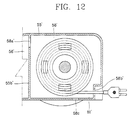
- Figure 12 is a side cross-sectional view showing the inner structure of a cord chamber in a vacuum cleaner according to still another embodiment of the present invention.
- a cord passage hole 58b' is formed in the rear of the case 55' so that an electrical cord 81' can be drawn therethrough, and at least one cooling hole 58a' is formed in a partition wall 55b' between the appliance chamber 56' and the cord chamber 58' so that the high temperature air generated in the cord chamber 58' can be discharged to the dust chamber 56'.
- an auxiliary port 58c communicated with the outside is formed.
- auxiliary port 58c can be formed as a round, square, or variously shaped opening.
- a cooling port 58a' is formed in an upper part of the cord chamber 58' to be communicated with the dust chamber 56'; so that the air of high temperature air is able to be discharged smoothly therethrough.
- auxiliary port 58c is formed in the lower part of the cord chamber 58', external air can be sufficiently sucked into the cord chamber 58' through the port 58c and the cord passage hole 58b', and therefore the electrical cord 81 is able to be cooled more efficiently.
- the air heated while passing through the fan motor assembly is directly discharged outside without contacting the case, and therefore even if the user operates the vacuum cleaner for a long time, distortion of the case caused by heated air discharged from the fan motor assembly is able to be prevented.
- the vacuum cleaner according to the present invention has a cooling port formed between the cord chamber and the dust chamber, whereby the electrical cord stored in the cord chamber is able to be cooled efficiently.
- the vacuum cleaner according to the present invention is constructed to reduce or cool the heat generated from the fan motor assembly and from the electrical cord, whereby the distortion of the case and heating of the electrical cord can be prevented. Accordingly, use of higher cost materials with high heat resistance and high durability is not required, and thereby the product cost can be reduced and a vacuum cleaner with higher output is able to be provided.
Landscapes
- Engineering & Computer Science (AREA)
- Mechanical Engineering (AREA)
- Electric Vacuum Cleaner (AREA)
- Electric Suction Cleaners (AREA)
- Filters For Electric Vacuum Cleaners (AREA)
Abstract
Description
Claims (15)
- A vacuum cleaner comprising :a case having a dust chamber for filtering dust included in sucked-in air, an appliance chamber communicated with the dust chamber for sucking filtered air from the dust chamber and discharging the air outside, and a cord chamber for storing a wound electrical cord therein;a fan motor assembly installed in the appliance chamber of the case for forcedly sucking the air in the appliance chamber and discharging the air;an exhaust duct means installed between the fan motor assembly and a discharge port in the case and guiding air discharged from the fan motor assembly to the discharge port; anda flowing passage means disposed between the dust chamber and the cord chamber for enabling the air to flow therebetween.
- A vacuum cleaner comprising :a case including a dust chamber for filtering dust included in sucked-in air, and an appliance chamber communicated with the dust chamber sucking the filtered air from the dust chamber and discharging the air outside through a discharge port of the case;a fan motor assembly installed inside the appliance chamber of the case for forcedly sucking the air from inside the dust chamber and discharging the air; andan exhaust duct means installed between the fan motor assembly and the discharge port of the case, for guiding air discharged from the fan motor assembly to the discharge port.
- The vacuum cleaner according to claim 2, wherein exhaust ports are formed in a peripheral surface of the fan motor assembly, and the exhaust duct means is extended from the peripheral surface of the fan motor assembly to the discharge port.
- The vacuum cleaner according to claim 2, wherein an acoustically absorbent member is installed between the fan motor assembly and the exhaust duct means.
- The vacuum cleaner according to claim 2, wherein exhaust ports are formed in a rear surface of the fan motor assembly, and the exhaust duct means is extended from the rear surface of the fan motor assembly to the discharge port.
- The vacuum cleaner according to claim 2, wherein a filter holder is formed at the discharge port of the case so that an exhaust filter can be installed thereat, and the exhaust duct means is fixed over the filter holder.
- A vacuum cleaner comprising :a case wherein a dust chamber for filtering dust included in sucked-in air and a cord passage chamber having a cord hole on one side thereof for storing a wound electrical cord therein are provided inside the case separated from each other; andat least one flowing passage means provided between the dust chamber and the cord chamber so that the air is able to flow therebetween.
- The vacuum cleaner according to claim 7, wherein a partition wall is formed between the dust chamber and the cord chamber, and the flowing passage means is formed by a port formed through the partition wall.
- The vacuum cleaner according to claim 7, wherein the flowing passage means communicates the dust chamber with an upper part of the cord chamber.
- The vacuum cleaner according to claim 9, wherein the cord passage hole is located in a lower part of the cord chamber.
- The vacuum cleaner according to claim 7, wherein the flowing passage means and the cord passage hole are located at opposite sides of the cord chamber from each other.
- The vacuum cleaner according to claim 7, wherein an auxiliary port communicated to the outside is formed in a lower part of the cord chamber of the case.
- The vacuum cleaner according to claim 12, wherein the flowing passage means is located in an upper part of the cord chamber.
- The vacuum cleaner according to claim 7, wherein the flowing passage means has a sectional area of not more than 20mm2.
- The vacuum cleaner according to claim 7, further comprising an appliance chamber for sucking the filtered air from inside the dust chamber and discharging the air outwardly, wherein the appliance chamber and the cord chamber are separated from each other and communicated with each other through the dust chamber.
Applications Claiming Priority (4)
| Application Number | Priority Date | Filing Date | Title |
|---|---|---|---|
| KR10-2000-0054845A KR100374170B1 (en) | 2000-09-19 | 2000-09-19 | Vacuum cleaner |
| KR2000054845 | 2000-09-19 | ||
| KR10-2000-0071306A KR100386254B1 (en) | 2000-11-28 | 2000-11-28 | Structure of cord room for vacuum cleaner |
| KR2000071306 | 2000-11-28 |
Publications (2)
| Publication Number | Publication Date |
|---|---|
| EP1188405A2 true EP1188405A2 (en) | 2002-03-20 |
| EP1188405A3 EP1188405A3 (en) | 2003-01-29 |
Family
ID=26638394
Family Applications (1)
| Application Number | Title | Priority Date | Filing Date |
|---|---|---|---|
| EP01402061A Withdrawn EP1188405A3 (en) | 2000-09-19 | 2001-07-30 | Vacuum cleaner with improved cooling |
Country Status (3)
| Country | Link |
|---|---|
| US (1) | US6611989B2 (en) |
| EP (1) | EP1188405A3 (en) |
| JP (1) | JP2002102122A (en) |
Cited By (2)
| Publication number | Priority date | Publication date | Assignee | Title |
|---|---|---|---|---|
| EP2039277A3 (en) * | 2007-09-20 | 2010-02-17 | Samsung Gwangju Electronics Co., Ltd. | Power cord cooling apparatus for a vacuum cleaner |
| CN103385670A (en) * | 2012-05-07 | 2013-11-13 | Lg电子株式会社 | Vacuum cleaner |
Families Citing this family (22)
| Publication number | Priority date | Publication date | Assignee | Title |
|---|---|---|---|---|
| KR100445470B1 (en) * | 2001-10-09 | 2004-08-21 | 엘지전자 주식회사 | Dirt and dust collecting casing and vacuum cleaner body having the same |
| KR100445479B1 (en) * | 2001-12-20 | 2004-08-21 | 엘지전자 주식회사 | Motor housing for vacuum cleaner |
| DE60223488T2 (en) * | 2001-12-21 | 2008-09-25 | Guido Valentini | Portable container for an electric hand tool with the ability to vacuum and collect dust |
| US7080425B2 (en) * | 2003-03-07 | 2006-07-25 | H-P Products, Inc. | Vacuum canister and mounting bracket for use therewith |
| KR101143773B1 (en) * | 2004-12-03 | 2012-05-11 | 엘지전자 주식회사 | Noise reduction system for fan-motor of vacuum cleaner |
| US7690077B2 (en) * | 2005-09-28 | 2010-04-06 | Electrolux Home Care Products, Ltd. | Central vacuum units with an acoustic damping pathway |
| KR100725515B1 (en) * | 2005-12-15 | 2007-06-08 | 삼성광주전자 주식회사 | Vacuum cleaner with motor noise reduction structure |
| KR101212291B1 (en) * | 2005-12-30 | 2012-12-12 | 삼성전자주식회사 | Vaccum Air Cleaner |
| KR100837362B1 (en) * | 2006-10-31 | 2008-06-12 | 삼성광주전자 주식회사 | Noise reduction device for motor for vacuum cleaner |
| CN101721165A (en) * | 2008-10-29 | 2010-06-09 | 乐金电子(天津)电器有限公司 | Vacuum dust collector |
| KR101566203B1 (en) * | 2009-04-21 | 2015-11-05 | 삼성전자 주식회사 | Fan motor apparatus for vacuum cleaner |
| KR20100116834A (en) * | 2009-04-23 | 2010-11-02 | 삼성광주전자 주식회사 | Upright type vacuum cleaner |
| KR20100137079A (en) * | 2009-06-22 | 2010-12-30 | 삼성광주전자 주식회사 | Vacuum cleaner with removable cord reel unit |
| WO2011002510A1 (en) * | 2009-07-01 | 2011-01-06 | Racine Industries, Inc. | Combination of carpet-cleaning machine and platform for transporting the machine |
| CN103313640A (en) * | 2010-12-01 | 2013-09-18 | 创科地板护理技术有限公司 | Wheel assembly for a vacuum cleaner |
| US8528167B2 (en) | 2011-01-05 | 2013-09-10 | Panasonic Corporation Of North America | Nozzle assembly including cord reel and agitator drive motor |
| US10085606B2 (en) | 2013-04-08 | 2018-10-02 | Emerson Electric Co. | Systems and apparatuses for cooling a vacuum device |
| KR20170019890A (en) * | 2015-08-13 | 2017-02-22 | 엘지전자 주식회사 | Vacuum cleaner |
| CN109832995B (en) * | 2017-11-24 | 2023-12-19 | 追觅科技(苏州)有限公司 | Dust collector |
| US11717124B2 (en) * | 2020-07-20 | 2023-08-08 | Omachron Intellectual Property Inc. | Evacuation station for a mobile floor cleaning robot |
| JP7078830B2 (en) * | 2020-11-09 | 2022-06-01 | アイリスオーヤマ株式会社 | Vacuum cleaner |
| US11737625B2 (en) * | 2020-12-04 | 2023-08-29 | Omachron Intellectual Property Inc. | Evacuation station for a mobile floor cleaning robot |
Family Cites Families (15)
| Publication number | Priority date | Publication date | Assignee | Title |
|---|---|---|---|---|
| US2272985A (en) * | 1939-10-14 | 1942-02-10 | Spencer Turbine Co | Motor mounting for vacuum cleaners |
| US3381329A (en) * | 1966-06-14 | 1968-05-07 | Sunbeam Corp | Vacuum cleaner |
| SE333800B (en) * | 1966-07-22 | 1971-03-29 | Electrolux Ab | |
| US3695006A (en) * | 1970-10-23 | 1972-10-03 | Dynamics Corp America | Vacuum cleaner |
| US3866263A (en) * | 1973-04-17 | 1975-02-18 | Hoover Co | Cleaner with auxiliary air flow |
| CH603133A5 (en) * | 1975-01-14 | 1978-08-15 | Hitachi Ltd | |
| DE2724249A1 (en) * | 1977-05-28 | 1978-11-30 | Mauz & Pfeiffer Progress | VACUUM CLEANERS, IN PARTICULAR HOUSEHOLD VACUUM CLEANERS |
| DE3042894C2 (en) * | 1980-11-13 | 1983-03-03 | Siemens AG, 1000 Berlin und 8000 München | Cylinder vacuum cleaner |
| US4533370A (en) * | 1982-03-30 | 1985-08-06 | Sharp Kabushiki Kaisha | Electric cleaner with minimum noise |
| US4547927A (en) * | 1983-12-08 | 1985-10-22 | Shop-Vac Corporation | Compact vacuum cleaner |
| JPH04303407A (en) * | 1991-03-29 | 1992-10-27 | Sanyo Electric Co Ltd | Vacuum cleaner |
| US5513417A (en) * | 1993-07-19 | 1996-05-07 | Samsung Electronics Co., Ltd. | Silencing device for vacuum cleaner |
| DE19616156C1 (en) * | 1996-04-23 | 1997-10-02 | Fakir Werk Gmbh & Co | Vacuum cleaner with housing comprising lower and upper parts |
| DE69816933T2 (en) * | 1997-10-27 | 2004-07-15 | Daewoo Electronics Corp. | Low-noise vacuum cleaner |
| CN1124417C (en) * | 1999-04-20 | 2003-10-15 | 三洋电机株式会社 | Motor wind blower and motor dust cleaner thereof |
-
2001
- 2001-07-30 EP EP01402061A patent/EP1188405A3/en not_active Withdrawn
- 2001-08-06 US US09/921,907 patent/US6611989B2/en not_active Expired - Lifetime
- 2001-08-07 JP JP2001238835A patent/JP2002102122A/en active Pending
Cited By (5)
| Publication number | Priority date | Publication date | Assignee | Title |
|---|---|---|---|---|
| EP2039277A3 (en) * | 2007-09-20 | 2010-02-17 | Samsung Gwangju Electronics Co., Ltd. | Power cord cooling apparatus for a vacuum cleaner |
| US7690485B2 (en) | 2007-09-20 | 2010-04-06 | Samsung Gwangju Electronics Co., Ltd. | Power cord cooling apparatus for a vacuum cleaner |
| AU2008202922B2 (en) * | 2007-09-20 | 2013-05-09 | Samsung Electronics Co., Ltd. | Power cord cooling apparatus for a vacuum cleaner |
| CN103385670A (en) * | 2012-05-07 | 2013-11-13 | Lg电子株式会社 | Vacuum cleaner |
| CN103385670B (en) * | 2012-05-07 | 2015-12-23 | Lg电子株式会社 | Vacuum cleaner |
Also Published As
| Publication number | Publication date |
|---|---|
| JP2002102122A (en) | 2002-04-09 |
| US20020032947A1 (en) | 2002-03-21 |
| EP1188405A3 (en) | 2003-01-29 |
| US6611989B2 (en) | 2003-09-02 |
Similar Documents
| Publication | Publication Date | Title |
|---|---|---|
| EP1188405A2 (en) | Vacuum cleaner with improved cooling | |
| EP0289987B1 (en) | Vacuum cleaner | |
| EP2360378B1 (en) | Blower with noise reduction device | |
| EP1842473A2 (en) | Electric motor housing for a vacuum cleaner fan assembly | |
| EP1617083A1 (en) | Electric pump | |
| CN101608630B (en) | Electric blower and electric duct collector equipped with the same | |
| JP2001178668A (en) | Vacuum cleaner | |
| CN220675896U (en) | Blowing and sucking integrated machine with double channels | |
| JP3597041B2 (en) | Electric blower and vacuum cleaner | |
| JPH11294390A5 (en) | ||
| JP5280960B2 (en) | Electric vacuum cleaner | |
| CN222828536U (en) | Floor brush assembly for cleaning device and cleaning device | |
| CN219895611U (en) | Cleaning apparatus | |
| KR100445649B1 (en) | The motor for a cleaner | |
| JPS591635Y2 (en) | vacuum cleaner | |
| JP2005137064A (en) | Electric blower and vacuum cleaner | |
| TWI843058B (en) | Electric blower and electric vacuum cleaner equipped with the same | |
| JP2001245829A (en) | Electric vacuum cleaner | |
| KR960014580B1 (en) | Power cord cooling structure of vacuum cleaner winding device | |
| KR200192862Y1 (en) | Exhaust structure of upright vacuum cleaner | |
| JP2010273754A (en) | Electric vacuum cleaner | |
| KR100437036B1 (en) | Centrifugal fan of vacuum cleaner | |
| KR100402887B1 (en) | Electric vacuum cleaner | |
| CN114795014A (en) | Heat dissipation roller and cleaning robot comprising same | |
| JPH11187989A (en) | Electric vacuum cleaner |
Legal Events
| Date | Code | Title | Description |
|---|---|---|---|
| PUAI | Public reference made under article 153(3) epc to a published international application that has entered the european phase |
Free format text: ORIGINAL CODE: 0009012 |
|
| AK | Designated contracting states |
Kind code of ref document: A2 Designated state(s): AT BE CH CY DE DK ES FI FR GB GR IE IT LI LU MC NL PT SE TR |
|
| AX | Request for extension of the european patent |
Free format text: AL;LT;LV;MK;RO;SI |
|
| PUAL | Search report despatched |
Free format text: ORIGINAL CODE: 0009013 |
|
| AK | Designated contracting states |
Designated state(s): AT BE CH CY DE DK ES FI FR GB GR IE IT LI LU MC NL PT SE TR |
|
| AX | Request for extension of the european patent |
Extension state: AL LT LV MK RO SI |
|
| 17P | Request for examination filed |
Effective date: 20030130 |
|
| AKX | Designation fees paid |
Designated state(s): DE FR GB |
|
| 17Q | First examination report despatched |
Effective date: 20071228 |
|
| R17C | First examination report despatched (corrected) |
Effective date: 20080116 |
|
| STAA | Information on the status of an ep patent application or granted ep patent |
Free format text: STATUS: THE APPLICATION IS DEEMED TO BE WITHDRAWN |
|
| 18D | Application deemed to be withdrawn |
Effective date: 20080527 |