EP1188064B1 - Determination of the polarization level of accumulated hyperpolarized noble gases during production - Google Patents
Determination of the polarization level of accumulated hyperpolarized noble gases during production Download PDFInfo
- Publication number
- EP1188064B1 EP1188064B1 EP00946838A EP00946838A EP1188064B1 EP 1188064 B1 EP1188064 B1 EP 1188064B1 EP 00946838 A EP00946838 A EP 00946838A EP 00946838 A EP00946838 A EP 00946838A EP 1188064 B1 EP1188064 B1 EP 1188064B1
- Authority
- EP
- European Patent Office
- Prior art keywords
- gas
- nmr
- coil
- polarized
- polarization
- Prior art date
- Legal status (The legal status is an assumption and is not a legal conclusion. Google has not performed a legal analysis and makes no representation as to the accuracy of the status listed.)
- Expired - Lifetime
Links
- 230000010287 polarization Effects 0.000 title claims abstract description 92
- 238000004519 manufacturing process Methods 0.000 title claims abstract description 35
- 229910052756 noble gas Inorganic materials 0.000 title claims abstract description 28
- 150000002835 noble gases Chemical class 0.000 title claims abstract description 10
- 239000007789 gas Substances 0.000 claims abstract description 274
- 230000003287 optical effect Effects 0.000 claims abstract description 75
- 238000012544 monitoring process Methods 0.000 claims abstract description 42
- 238000005086 pumping Methods 0.000 claims abstract description 39
- FHNFHKCVQCLJFQ-YPZZEJLDSA-N xenon-129 atom Chemical compound [129Xe] FHNFHKCVQCLJFQ-YPZZEJLDSA-N 0.000 claims abstract description 33
- 238000004891 communication Methods 0.000 claims abstract description 14
- 239000012530 fluid Substances 0.000 claims abstract description 12
- 230000005291 magnetic effect Effects 0.000 claims description 51
- 238000000034 method Methods 0.000 claims description 49
- 238000001514 detection method Methods 0.000 claims description 38
- 229910052783 alkali metal Inorganic materials 0.000 claims description 18
- 150000001340 alkali metals Chemical class 0.000 claims description 18
- 230000005284 excitation Effects 0.000 claims description 17
- 239000012071 phase Substances 0.000 claims description 10
- 238000010257 thawing Methods 0.000 claims description 8
- 238000000711 polarimetry Methods 0.000 claims description 3
- 239000007792 gaseous phase Substances 0.000 claims 1
- 230000009977 dual effect Effects 0.000 abstract description 12
- 238000005481 NMR spectroscopy Methods 0.000 description 160
- 210000004027 cell Anatomy 0.000 description 95
- 230000008569 process Effects 0.000 description 19
- 238000005259 measurement Methods 0.000 description 18
- 239000000203 mixture Substances 0.000 description 15
- XLYOFNOQVPJJNP-UHFFFAOYSA-N water Chemical compound O XLYOFNOQVPJJNP-UHFFFAOYSA-N 0.000 description 15
- 229910052724 xenon Inorganic materials 0.000 description 15
- FHNFHKCVQCLJFQ-UHFFFAOYSA-N xenon atom Chemical compound [Xe] FHNFHKCVQCLJFQ-UHFFFAOYSA-N 0.000 description 15
- 238000009825 accumulation Methods 0.000 description 13
- 238000009428 plumbing Methods 0.000 description 12
- 239000000463 material Substances 0.000 description 11
- 239000007787 solid Substances 0.000 description 9
- 239000011521 glass Substances 0.000 description 8
- 239000007788 liquid Substances 0.000 description 8
- 239000003990 capacitor Substances 0.000 description 7
- 230000001965 increasing effect Effects 0.000 description 7
- 238000002595 magnetic resonance imaging Methods 0.000 description 7
- 230000004044 response Effects 0.000 description 7
- 239000000047 product Substances 0.000 description 6
- 230000002829 reductive effect Effects 0.000 description 6
- 230000003068 static effect Effects 0.000 description 6
- 101100043261 Caenorhabditis elegans spop-1 gene Proteins 0.000 description 5
- 238000004458 analytical method Methods 0.000 description 5
- 238000010992 reflux Methods 0.000 description 5
- IJGRMHOSHXDMSA-UHFFFAOYSA-N Atomic nitrogen Chemical compound N#N IJGRMHOSHXDMSA-UHFFFAOYSA-N 0.000 description 4
- 238000010521 absorption reaction Methods 0.000 description 4
- 230000004907 flux Effects 0.000 description 4
- 229910052734 helium Inorganic materials 0.000 description 4
- 230000002102 hyperpolarization Effects 0.000 description 4
- 238000003384 imaging method Methods 0.000 description 4
- 238000002955 isolation Methods 0.000 description 4
- 238000000926 separation method Methods 0.000 description 4
- 238000004804 winding Methods 0.000 description 4
- 230000008859 change Effects 0.000 description 3
- 238000000576 coating method Methods 0.000 description 3
- 230000002999 depolarising effect Effects 0.000 description 3
- 238000010586 diagram Methods 0.000 description 3
- 230000007613 environmental effect Effects 0.000 description 3
- 230000005283 ground state Effects 0.000 description 3
- 238000000669 high-field nuclear magnetic resonance spectroscopy Methods 0.000 description 3
- 239000012535 impurity Substances 0.000 description 3
- 238000010997 low field NMR spectroscopy Methods 0.000 description 3
- 230000007246 mechanism Effects 0.000 description 3
- 229910052751 metal Inorganic materials 0.000 description 3
- 239000002184 metal Substances 0.000 description 3
- 238000012986 modification Methods 0.000 description 3
- 230000004048 modification Effects 0.000 description 3
- 230000035945 sensitivity Effects 0.000 description 3
- 239000000126 substance Substances 0.000 description 3
- 238000012546 transfer Methods 0.000 description 3
- 238000011144 upstream manufacturing Methods 0.000 description 3
- RZVAJINKPMORJF-UHFFFAOYSA-N Acetaminophen Chemical compound CC(=O)NC1=CC=C(O)C=C1 RZVAJINKPMORJF-UHFFFAOYSA-N 0.000 description 2
- RYGMFSIKBFXOCR-UHFFFAOYSA-N Copper Chemical compound [Cu] RYGMFSIKBFXOCR-UHFFFAOYSA-N 0.000 description 2
- XEEYBQQBJWHFJM-UHFFFAOYSA-N Iron Chemical compound [Fe] XEEYBQQBJWHFJM-UHFFFAOYSA-N 0.000 description 2
- 210000005056 cell body Anatomy 0.000 description 2
- 239000000919 ceramic Substances 0.000 description 2
- 239000004020 conductor Substances 0.000 description 2
- 230000001419 dependent effect Effects 0.000 description 2
- 230000008014 freezing Effects 0.000 description 2
- 238000007710 freezing Methods 0.000 description 2
- 239000001307 helium Substances 0.000 description 2
- SWQJXJOGLNCZEY-UHFFFAOYSA-N helium atom Chemical compound [He] SWQJXJOGLNCZEY-UHFFFAOYSA-N 0.000 description 2
- 239000007791 liquid phase Substances 0.000 description 2
- 230000005415 magnetization Effects 0.000 description 2
- 230000028161 membrane depolarization Effects 0.000 description 2
- 229910052757 nitrogen Inorganic materials 0.000 description 2
- 231100000252 nontoxic Toxicity 0.000 description 2
- 230000003000 nontoxic effect Effects 0.000 description 2
- 230000010355 oscillation Effects 0.000 description 2
- 230000005298 paramagnetic effect Effects 0.000 description 2
- 239000005297 pyrex Substances 0.000 description 2
- 230000001105 regulatory effect Effects 0.000 description 2
- 230000000717 retained effect Effects 0.000 description 2
- 229910052701 rubidium Inorganic materials 0.000 description 2
- IGLNJRXAVVLDKE-UHFFFAOYSA-N rubidium atom Chemical compound [Rb] IGLNJRXAVVLDKE-UHFFFAOYSA-N 0.000 description 2
- 238000004611 spectroscopical analysis Methods 0.000 description 2
- 230000007704 transition Effects 0.000 description 2
- 101100493712 Caenorhabditis elegans bath-42 gene Proteins 0.000 description 1
- 229920006074 Nylatron® Polymers 0.000 description 1
- 238000003324 Six Sigma (6σ) Methods 0.000 description 1
- ATJFFYVFTNAWJD-UHFFFAOYSA-N Tin Chemical compound [Sn] ATJFFYVFTNAWJD-UHFFFAOYSA-N 0.000 description 1
- 229920003997 Torlon® Polymers 0.000 description 1
- 229920004738 ULTEM® Polymers 0.000 description 1
- 230000003213 activating effect Effects 0.000 description 1
- 230000002411 adverse Effects 0.000 description 1
- 239000003513 alkali Substances 0.000 description 1
- 229910000323 aluminium silicate Inorganic materials 0.000 description 1
- 238000013459 approach Methods 0.000 description 1
- 230000015556 catabolic process Effects 0.000 description 1
- 239000011248 coating agent Substances 0.000 description 1
- 238000010924 continuous production Methods 0.000 description 1
- 229910052802 copper Inorganic materials 0.000 description 1
- 239000010949 copper Substances 0.000 description 1
- 230000001351 cycling effect Effects 0.000 description 1
- 230000006378 damage Effects 0.000 description 1
- 230000003247 decreasing effect Effects 0.000 description 1
- 238000006731 degradation reaction Methods 0.000 description 1
- 230000000694 effects Effects 0.000 description 1
- 230000008030 elimination Effects 0.000 description 1
- 238000003379 elimination reaction Methods 0.000 description 1
- 238000005516 engineering process Methods 0.000 description 1
- 230000034964 establishment of cell polarity Effects 0.000 description 1
- 230000005281 excited state Effects 0.000 description 1
- -1 frozen Substances 0.000 description 1
- 238000007496 glass forming Methods 0.000 description 1
- 238000009532 heart rate measurement Methods 0.000 description 1
- SWQJXJOGLNCZEY-BJUDXGSMSA-N helium-3 atom Chemical compound [3He] SWQJXJOGLNCZEY-BJUDXGSMSA-N 0.000 description 1
- 238000001727 in vivo Methods 0.000 description 1
- 238000010978 in-process monitoring Methods 0.000 description 1
- 230000006698 induction Effects 0.000 description 1
- 230000001939 inductive effect Effects 0.000 description 1
- 230000003993 interaction Effects 0.000 description 1
- 229910052742 iron Inorganic materials 0.000 description 1
- 230000001678 irradiating effect Effects 0.000 description 1
- 230000000670 limiting effect Effects 0.000 description 1
- 239000003607 modifier Substances 0.000 description 1
- 239000012811 non-conductive material Substances 0.000 description 1
- 230000036961 partial effect Effects 0.000 description 1
- 238000007747 plating Methods 0.000 description 1
- 229920000642 polymer Polymers 0.000 description 1
- 239000002244 precipitate Substances 0.000 description 1
- 238000012545 processing Methods 0.000 description 1
- 238000005057 refrigeration Methods 0.000 description 1
- 238000004904 shortening Methods 0.000 description 1
- 239000007790 solid phase Substances 0.000 description 1
- 238000003860 storage Methods 0.000 description 1
- 229920001169 thermoplastic Polymers 0.000 description 1
- 239000004416 thermosoftening plastic Substances 0.000 description 1
Images





Classifications
-
- G—PHYSICS
- G01—MEASURING; TESTING
- G01R—MEASURING ELECTRIC VARIABLES; MEASURING MAGNETIC VARIABLES
- G01R33/00—Arrangements or instruments for measuring magnetic variables
- G01R33/20—Arrangements or instruments for measuring magnetic variables involving magnetic resonance
- G01R33/28—Details of apparatus provided for in groups G01R33/44 - G01R33/64
-
- G—PHYSICS
- G01—MEASURING; TESTING
- G01R—MEASURING ELECTRIC VARIABLES; MEASURING MAGNETIC VARIABLES
- G01R33/00—Arrangements or instruments for measuring magnetic variables
- G01R33/20—Arrangements or instruments for measuring magnetic variables involving magnetic resonance
- G01R33/28—Details of apparatus provided for in groups G01R33/44 - G01R33/64
- G01R33/281—Means for the use of in vitro contrast agents
Definitions
- the present invention relates to the collection and accumulation of polarized noble gases, and relates more particularly to the determination of the level of polarization of hyperpolarized gases used in NMR and magnetic resonance imaging ("MRI”) applications.
- MRI magnetic resonance imaging
- polarized inert noble gases can produce improved MRI images of certain areas and regions of the body which have heretofore produced less than satisfactory images in this modality.
- Polarized helium-3 (“ 3 He”) and xenon-129 (“ 129 Xe”) have been found to be particularly suited for this purpose.
- the polarized state of the gases are sensitive to handling and environmental conditions and can, undesirably, decay from the polarized state relatively quickly. Further, because of the sensitivity of the polarized gas, it is desirable to monitor the polarization level of the gas at various times during the product's life.
- in-process monitoring can indicate the polarization achieved during the optical pumping process (described below) or the polarization lost at certain phases of the life cycle process (so as to determine the remaining useable life of the polarized gas or to help identify critical production path issues).
- Hyperpolarizers are used to produce and accumulate polarized noble gases. Hyperpolarizes artificially enhance the polarization of certain noble gas nuclei (such as 129 Xe or 3 He) over the natural or equilibrium levels, i . e ., the Boltzmann polarization. Such an increase is desirable because it enhances and increases the MRI signal intensity, allowing physicians to obtain better images of the substance in the body. See U. S. Patent No. 5,545,396 to Albert et al.
- the noble gas is typically blended with optically pumped alkali metal vapors such as rubidium ("Rb"). These optically pumped metal vapors collide with the nuclei of the noble gas and hyperpolarize the noble gas through a phenomenon known as "spin-exchange.”
- the "optical pumping" of the alkali metal vapor is produced by irradiating the alkali-metal vapor with circularly polarized light at the wavelength of the first principal resonance for the alkali metal ( e.g. , 795 nm for Rb). Generally stated, the ground state atoms become excited, then subsequently decay back to the ground state.
- the hyperpolarized gas is separated from the alkali metal prior to introduction into a patient (to form a non-toxic pharmaceutically acceptable product).
- the hyperpolarized gas can deteriorate or decay relatively quickly (lose its hyperpolarized state) and therefore must be handled, collected, transported, and stored carefully.
- handling of the hyperpolarized gases is critical, because of the sensitivity of the hyperpolarized state to environmental and handling factors and the potential for undesirable decay of the gas from its hyperpolarized state.
- Some accumulation systems employ cryogenic accumulators to separate the buffer gas from the polarized gas and to freeze the collected polarized gas. to Driehuys et.
- the level of polarization has been monitored at the polarization transfer process point (i.e., at the polarizer or optical cell) in a hyperpolarizer device or measured at a site remote from the hyperpolarizer after the polarized gas is dispensed from the hyperpolarizer (see, e.g., US-A-5 642 625 disclosing a hyperpolarizer according to the preamble of claim 1).
- the polarized gas is directed to an exit or dispensing port on the hyperpolarizer and into two separate sealable containers, a gas delivery container, such as a bag, and a small (about 5 cubic centimeter) sealable glass bulb specimen container.
- This glass bulb specimen container is then sealed at the hyperpolarizer site and then carried away from the hyperpolarizer to a remotely located high-field NMR spectroscopy unit (4.7T) to determine the level of polarization achieved during the polarization process.
- a remotely located high-field NMR spectroscopy unit 4.7T
- conventional hyperpolarizers may also monitor the polarization level achieved at the polarization transfer process point, i.e ., at the optical cell or optical pumping chamber.
- a small "surface" NMR coil is positioned adjacent the optical pumping chamber to excite and detect the gas therein and thus monitor the level of polarization of the gas during the polarization-transfer process.
- the small surface NMR coil will sample a smaller volume of the proximate polarized gas and thus have a longer transverse relaxation time (T 2 *) compared to larger NMR coil configurations.
- T 2 * transverse relaxation time
- a relatively large tip angle pulse can be used to sample the local-spin polarization. The large angle pulse will generally destroy the local polarization, but because the sampled volume is small compared to the total size of the container, it will not substantially affect the overall polarization of the gas.
- the surface NMR coil is operably associated with low-field NMR detection equipment which is used to operate the NMR coil and to analyze the detected signals.
- low-field NMR detection equipment used to monitor polarization at the optical cell and to record and analyze the NMR signals associated therewith include low-field spectrometers using frequency synthesizers, lock-in amplifiers, audio power amplifiers, and the like, as well as computers.
- on-board hyperpolarizer monitoring equipment no longer requires high-field NMR equipment, but instead can use low-field detection techniques to perform polarization monitoring for the optical cell at much lower field strengths (e . g ., 10 -4 -10 -2 T (1-100G)) than conventional high-field NMR techniques.
- This lower field strength allows correspondingly lower detection equipment operating frequencies, such as 1-400kHz.
- AFP adiabatic fast passage
- Saam et al. has proposed a low-frequency NMR circuit expressly for the on-board detection of polarization levels for hyperpolarized 3 He at the optical cell inside the temperature-regulated oven which encloses the cell. See Saam et al., Low Frequency NMR Polarimeter for Hyperpolarized Gases, Jnl. of Magnetic Resonance 134, 67-71 (1998). Magnetic Imaging Technologies, Inc. ("MITI”) and others have used low-field NMR apparatus for on-board polarization measurement.
- MITI Magnetic Imaging Technologies, Inc.
- a first aspect of the invention is directed to a hyperpolarizer for producing polarized noble gases.
- the hyperpolarizer comprises an optical pumping cell having a non-polarized gas inlet port and a polarized gas outlet port and a magnetic field source operably associated with the optical pumping cell.
- the magnetic field source is configured to provide a region of homogeneity.
- the hyperpolarizer also includes a NMR coil having first and second opposing ends. The first end is positioned adjacent the optical pumping cell within the region of homogeneity.
- the hyperpolarizer also includes a cryogenic accumulator in fluid communication with the optical pumping cell outlet port and a polarized gas dispensing port in fluid communication with the cryogenic accumulator.
- a polarized gas exit flow path extends between said cryogenic accumulator and the polarized gas dispensing outlet and a secondary reservoir is positioned adjacent the NMR coil second end in fluid communication with the polarized gas exit flow path.
- the NMR coil is configured to excite one of a quantity of polarized gas positioned in the optical cell and a quantity of polarized gas positioned in the secondary reservoir.
- the NMR coil primarily monitors the polarization in the optical cell during operation of the cell, but during post-thaw, the polarization in the optical cell is gone and the only measurable signal will arise from the polarized gas in the post thaw bulb.
- the magnetic field source defines a region of homogeneity which includes a portion of the optical pumping cell and a (spatial) volume which extends a distance below the optical pumping cell.
- the NMR coil is positioned on a bottom portion of the optical pumping cell, and the NMR coil and at least a portion of the secondary reservoir are positioned within the region of homogeneity.
- a preferred method of operating an NMR coil positioned proximate to the optical cell outlet port includes flowing the hyperpolarized gas through the optical cell and out the port at a desired rate.
- the hyperpolarized gas flow is preferably temporally stopped or slowed and a NMR signal is taken via the coil on the outlet port (or arm) and the flow is then resumed.
- This configuration and method can generate a signal which is representative of the flowing hyperpolarized gas as it exits the optical cell.
- Yet another aspect of the present invention is a method for monitoring the polarization level of polarized gas during production, as defined in claim 9.
- the optical pumping chamber has a primary body portion and a polarized gas exit port defined by a longitudinally extending leg, and the NMR excitation coil is positioned around the leg adjacent the primary body portion of the optical pumping chamber.
- the method further comprise cryogenically accumulating the polarized gas in a cryogenic accumulator during which a portion of the polarized gas is frozen and then subsequently thawing the frozen polarized gas prior to the dispensing step and after the thawing step. It is also preferred that during or after the thawing step, a minor portion of the quantity of thawed polarized gas is directed away from a major portion of the hyperpolarized gas into the gas flow path proximate to the NMR coil.
- the present invention can monitor the polarization during production and even at the dispensing port where convenient MRI patient-sized quantities (such as 0.5-2 liters of polarized gas) are directed out of the hyperpolarizer.
- convenient MRI patient-sized quantities such as 0.5-2 liters of polarized gas
- the polarization level at shipping or before storage is readily identifiable before the container is detachably released from the hyperpolarizer unit for easy transport to a remote site.
- the improved on-board in-process polarization monitoring can improve production and conveniently indicate the level of polarization of gas at several key points including at the dispensing port.
- the dual symmetry NMR coil can allow a single NMR coil to measure polarization both at the optical cell during the optical pumping process and at a second point in the production cycle, such as at a post-thaw position.
- the instant invention now configures a cold finger to release cryogenically accumulated hyperpolarized xenon dependent on a more predictable indicator, pressure. Because the release of the thawed gas at a predetermined pressure is less dependent on process variations such as flow rates and collected quantities of gas, a more predictable process can be obtained, thereby providing a more reliably controllable production capability.
- forward and derivatives thereof refer to the general direction the gas mixture travels as it moves through the hyperpolarizer unit; this term is meant to be synonymous with the term “downstream” which is often used in manufacturing environments to indicate that certain material being acted upon is farther along in the manufacturing process than other material.
- downstream which is often used in manufacturing environments to indicate that certain material being acted upon is farther along in the manufacturing process than other material.
- reverse and upstream and derivatives thereof refer to the directions opposite, respectively, the forward and downstream directions.
- polarized gases are collected, frozen, thawed, and used in MRI applications.
- the term “frozen polarized gas” means that the polarized gas has been frozen into a solid state.
- liquid polarized gas means that the polarized gas has been or is being liquefied into a liquid state.
- gas has been used in certain places to descriptively indicate a hyperpolarized noble gas product and may be used with modifiers such as solid, frozen, and liquid to describe the state or phase of that product.
- hyperpolarize means to artificially enhance the polarization of certain noble gas nuclei over the natural or equilibrium levels. Such an increase is desirable because it allows stronger imaging signals corresponding to better MRI images of the substance and a targeted area of the body.
- hyperpolarization can be induced by spin-exchange with an optically pumped alkali-metal vapor or alternatively by metastability exchange. See Albert et al., U.S. Patent No. 5,545,396.
- Figure 1 illustrates a preferred hyperpolarizer unit 10 .
- This is a high-volume unit which is configured to produce and accumulate spin-polarized noble gases substantially continually, i.e. , the flow of gas through the optical cell is substantially continuous during accumulation.
- the unit 10 includes a noble gas mixture supply 12 and a supply regulator 14.
- a purifier 16 is positioned in the line to remove impurities such as water vapor from the system as will be discussed further below.
- the hyperpolarizer unit 10 also includes a flow meter 18 and an inlet valve 20 positioned upstream of a polarizer or optical cell 22.
- An optic light source such as a laser 26 (preferably a diode laser array) is directed into the polarizer cell 22 through various focusing and light distributing means 24, such as lenses, mirrors, and the like.
- the laser 26 is circularly polarized to optically pump alkali metals in the cell 22.
- the cell 22 is positioned inside a temperature-regulated oven (schematically illustrated by a double dotted line) 122.
- An additional valve 28 is positioned downstream of the polarizer cell 22.
- a cold finger or accumulator 30 is connected to the hyperpolarizer unit 10 by a pair of releasable mechanisms such as threaded members or quick disconnects 31, 32. This allows the accumulator 30 to be easily detached, removed, or added, to and from the system 10.
- the accumulator 30 is operably associated with a cold source or refrigeration means 42.
- the cold source 42 is a liquid cryogen bath 43.
- the accumulator 30 will be discussed in more detail hereinbelow.
- the hyperpolarizer 10 also includes a vacuum pump 60 is in communication with the system. Additional valves to control flow and direct exit gas are shown at various points (shown as 52, 55). A shut-off valve 47 is positioned adjacent an "on-board" exit gas tap 50. Certain of the valves downstream of the accumulator 30 are used for "on-board" thawing and delivery of the collected polarized gas as will be described further below.
- the unit 10 also includes a digital pressure transducer 54 and flow control means 57 along with a shut-off valve 58.
- the shut-off valve 58 preferably controls the flow of gas through the entire unit 10; it is used to turn the gas flow on and off, as will be described below.
- other flow control mechanisms, and devices may be used within the scope of the present invention.
- a gas mixture is introduced into the unit 10 at the gas source 12.
- the source 12 is a pressurized gas tank which holds a pre-mixed gas mixture.
- a gas mixture is introduced into the hyperpolarizer apparatus upstream of the polarizer cell 22.
- Most xenon gas mixtures include a buffer gas as well as a lean amount of the gas targeted for hyperpolarization and are preferably produced in a continuous flow system.
- the pre-mixed gas mixture is about 85-98% He (preferably about 85-89% He), about 5% or less 129 Xe, and about 1-10% N 2 (preferably about 6-10%).
- hyperpolarized 3 He a typical mixture of about 99.25% 3 He and 0.75% N 2 is pressurized to 8 atm (0.81 MPa) or more and heated and exposed to the optical laser light source, typically in a batch mode system.
- the hyperpolarized gas exits the polarizer cell (i . e ., the pumping chamber) 22, it is directed to a collection or accumulation container.
- the pre-mixed gas mixture includes a lean noble gas (the gas to be hyperpolarized) and buffer gas mixture.
- the gas mixture is passed through the purifier 16 and introduced into the polarizer cell 22.
- the valves 20, 28 are on/off valves operably associated with the polarizer cell 22 .
- the gas regulator 14 preferably steps down the pressure from the gas tank source 12 (typically operating at 2000 psi or 136 atm (13.8 MPa)) to about 6-10 atm (0.61-1.01 MPa) for the system.
- the entire manifold (conduit, polarized cell, accumulator, etc.) is pressurized to the cell pressure (about 6-10 atm (0.61-1.01 MPa)).
- the flow in the unit 10 is activated by opening valve 58 and is controlled by adjusting the flow control means 57 .
- the typical residence time of the gas in the cell 22 is about 10-30 seconds; i . e ., it takes on the order of 10-30 seconds for the gas mixture to be hyperpolarized while moving through the cell 22.
- the gas mixture is preferably introduced into the cell 22 at a pressure of about 6-10 atm (0.61-1.01 MPa).
- operating pressures of above 10 atm (1.01 MPa) such as about 20-30 atm (2.01-3.04 MPa) are preferred to pressure broaden the alkali metal (such as rubidium (“Rb”)) and facilitate the absorption of (approaching up to 100%) of the optical light.
- the polarizer cell 22 is a high pressure optical pumping cell housed in a heated chamber with apertures configured to allow entry of the laser emitted light.
- the hyperpolarizer unit 10 hyperpolarizes a selected noble gas such as 129 Xe (or 3 He) via a conventional spin-exchange process.
- a vaporized alkali metal such as Rb is introduced into the polarizer cell 22.
- the Rb vapor is optically pumped via an optic light source 26 , preferably a diode laser.
- the unit 10 employs helium buffer gas to pressure broaden the Rb vapor absorption bandwidth.
- the selection of a buffer gas is important because the buffer gas - while broadening the absorption bandwidth - can also undesirably impact the alkali metal-noble gas spin-exchange by potentially introducing an angular momentum loss of the alkali metal to the buffer gas rather than to the noble gas as desired.
- 129 Xe is hyperpolarized through spin exchange with the optically pumped Rb vapor. It is also preferred that the unit 10 use a helium buffer gas with a pressure many times greater than the 129 Xe pressure for pressure broadening in a manner which minimizes Rb spin destruction.
- Rb is reactive with H 2 O. Therefore, any water or water vapor introduced into the polarizer cell 22 can cause the Rb to lose laser absorption and decrease the amount or efficiency of the spin-exchange in the polarizer cell 22 .
- an extra filter or purifier (not shown) can be positioned before the inlet of the polarizer cell 22 with extra surface area to remove even additional amounts of this undesirable impurity in order to further increase the efficiency of the polarizer.
- Hyperpolariaed gas exits the polarizer cell 22 and enters a collection reservoir 75 located at the bottom of the accumulator 30 .
- the hyperpolarized gas is exposed to temperatures below its freezing point and collected as a frozen product 100 in the reservoir 75 .
- the hyperpolarized gas is collected (as well as stored, transported, and preferably thawed) in the presence of a magnetic field, generally on the order of at least 500 Gauss (0.05 Tesla), and typically about 2kilo Gauss (0.2 Tesla), although higher fields can be used. Lower fields can potentially undesirably increase the relaxation rate or decrease the relaxation time of the polarized gas.
- the magnetic field is provided by permanent magnets 40 positioned in the cryogen bath and arranged about a magnetic yoke 41 .
- the hyperpolarizer unit 10 can also capitalize on the temperature change in the outlet line between the heated pumping cell 22 and the refrigerated cold trap or accumulator 30 to precipitate the alkali metal from the polarized gas stream in the conduit above the accumulator 30.
- the alkali metal can precipitate out of the gas stream at temperatures of about 40°C.
- the unit 10 can also include an alkali metal reflux condenser (not shown) or post-cell filter (not shown).
- the refluxing condenser employs a vertical refluxing outlet pipe which is kept at room temperature.
- the gas flow velocity through the refluxing pipe and the size of the refluxing outlet pipe is such that the alkali metal vapor condenses and drips back into the pumping cell by gravitational force.
- a Rb filter can be used to remove excess Rb from the hyperpolarized gas prior to collection or accumulation.
- valve 28 is closed, leaving the cell 22 pressurized. This allows the accumulator 30 and the downstream plumbing to begin to depressurize because the flow valve 58 is open. Preferably, the portion of the unit 10 downstream of the valve 28 is allowed to depressurize to about 1.5 atm before the flow valve 58 is closed. After closing the flow valve 58, valve 55 can be opened to evacuate the remaining gas in the manifold. Once the outlet plumbing is evacuated, valves 35 and 37 are closed. If the collected gas is to be distributed "on-board," i.e.
- a receptacle such as a bag 525 or other vessel as shown in Figure 9, can be attached to the outlet 50.
- the valve 47 can be opened to evacuate the attached bag.
- valve 52 can be optionally closed. This minimizes the contact of the polarized gas with the pressure transducer region 59 of the unit 10.
- This region can include materials that have a depolarizing effect on the polarized gas. Thus, long contact times with this region may promote relaxation of the polarized gas.
- valve 55 is preferably closed to prevent the evacuation of polarized thawed gases. It is also preferred that the flow channels on the downstream side of the cell 22 (including the secondary reservoir and bleed line discussed below) are formed from materials which minimize the contact-induced depolarization effect on the polarized state of the gas. Coatings can also be used such as those described in U.S. Patent No. 5,612,103.
- valve 37 In the "on-board" thaw operation, valve 37 is opened to let the gas out. It then proceeds through valve 47 and out outlet 50.
- accumulator first and second isolation valves 35, 37 are closed after the depressurization and evacuation of the accumulator 30. Evacuating the accumulator 30 allows any residual gas in the accumulator 30 to be removed. Leaving gas in the accumulator 30 with the frozen polarized gas may contribute to the heat load on the frozen gas, possibly raising the temperature of the frozen gas and potentially shortening the relaxation time. Thus, in a preferred embodiment, after depressurization and evacuation and closing the isolation valves 35, 37, the accumulator 30 is disconnected from the unit 10 via release points 31, 32.
- the isolation valves 35, 37 are in communication with the primary flow channel 80 and the buffer gas exit channel 90 respectively and each can adjust the amount of flow therethrough as well as close the respective paths to isolate the accumulator from the unit 10 and the environment.
- another accumulator 30 can be easily and relatively quickly attached to the release points 31, 32.
- the outlet manifold is evacuated using valve 55 (with valves 52, 35, 37 open).
- valve 55 is closed.
- Valve 28 is then re-opened which repressurizes the outlet manifold to the operating cell pressure.
- Valve 58 is then opened to resume flow in the unit 10.
- a preferred hyperpolarizer unit 10 is configured to provide a continuous flow of hyperpolarized 129 Xe gas for continuous production and accumulation of same.
- a NMR excitation coil was positioned in the oven 122 adjacent the optical cell 22 (also in the oven) to determine the polarization level achieved by the gas in the cell 22.
- at least one laboratory has also used a small sealable (about 5cc) glass bulb which was filled with a sample of hyperpolarized gas at the same point as the collection vessel or dose bag. The small bulb was then taken to a separate 4.7T spectrometer to determine the level of polarization associated with the collection vessel.
- the present invention now conveniently provides for an on-board (on the hyperpolarizer unit 10) polarization level measurement associated with the polarized gas at various points in the production cycle, such as at both at the polarizer cell 22 and one or more pre-dispensing and post-thaw gas production point(s).
- the (post-thaw) gas exit path 113 starts at the cold finger accumulator 30, extends down the exit line 113a to valve 47 and then to dispensing outlet line 114.
- the dispensing-outlet line 114 ends at the xenon outlet 50.
- a small bleed line 115 is in fluid communication with the xenon outlet 50.
- the bleed line 115 is connected to the dispensing outlet line 114 a distance above the xenon outlet 50.
- the bleed line 115 can be alternatively positioned along the exit line 113a, but is preferably positioned adjacent the dispensing outlet 50 to provide a more reliable indication of the polarized state of the gas at the outlet 50.
- the bleed line 115 is in fluid communication with the dispensing outlet line 114 and defines a secondary flow path for the hyperpolarized gas, the bleed line 115 being configured and sized to direct a small quantity of the hyperpolarized gas to the secondary reservoir 120.
- a quantity of hyperpolarized gas is cryogenically accumulated as described above to collect a quantity of hyperpolarized 129 Xe in frozen or ice form.
- Valves 35 and 37 are closed.
- the frozen hyperpolarized 129 Xe gas is then warmed, preferably by applying heat and increasing the pressure in the accumulator 30 such that the solid transitions substantially directly to liquid phase.
- the xenon isolation valve 52 is closed and the accumulator 30 is opened via valve 37 to allow the post thaw gas to enter the exit line 113 through gate 32.
- valve 47 into the dispensing outlet line 114 and a majority of the gas is directed to a collection vessel at the xenon outlet 50.
- valve 52 can remain open, but it is preferred that valve 55 be closed for pressure monitoring.
- the hyperpolarizer unit 10 has been reconfigured to operate with potentially even more reliable thaws according to one aspect of the present invention.
- previous thaw methods have provided increased post-thaw polarization levels.
- a waiting period typically set at about 8 seconds
- the "optimal" hold time or waiting period can vary depending on the quantity of gas accumulated, the flow rate used during accumulation, and the like.
- the hyperpolarizer unit 10 is configured to monitor the pressure of the gas in the (downstream) plumbing associated with the cold finger 30 and then to release the thawed gas at a predetermined pressure rather than at a preset time.
- the hyperpolarizer unit 10 is configured to minimize the dead volumes in the plumbing between valve 37 and valve 52 as well as the pressure transducer dead volume (52-54).
- the thaw method is performed with cold finger valve 37 open, the valve 47 still closed, the valve 52 open, and the valves 55 and 58 still closed.
- This configuration adds a small dead volume of about 7.3 cc's to the cold finger 30, the internal volume of which is typically about 22 cc's.
- the pressure monitoring now provided allows a more predictable and repeatable opening of the valve associated with the control of the gas exiting the cold finger 30 (now valve 47). That is, during thaw, a major portion of the hyperpolarized gas transitions directly from a frozen solid into a liquid phase corresponding to the pressure in the cold finger during the thawing step.
- the predetermined release pressure is set at about at least 1 atmosphere (0.1 MPa). Opening the valve after the pressure reaches 1 atm has shown improved xenon post thaw release for 100-600 cc's of accumulated 129 Xe. Interestingly, lowering the release pressure (such as to 0.8 atm (0.08 MPa)) can introduce unreliable post-thaw polarization levels and slow the rate at which the polarized gas exits the cold finger.
- polarized thawed 129 Xe is directed into the dead volume in a post-thaw path (the path downstream of valve 47 and between valves 52-55-58) and may depolarize therein, the rapid release of the thawed polarized gas once valve 47 is opened is such that little of the depolarized gas enters into the exit path 114,114a (i.e., once valve 47 opens, substantially all of the thawed gas flows into the path defined between valves 37-47-50).
- depolarized gas in the dead volumes mix with the primary polarized thaw gas, it is a relatively small volume compared to the typical collection volumes that the overall polarization is minimally reduced.
- other pressure monitoring sensors and plumbing configurations can also be employed, in which the pressure monitor and plumbing are configured to minimize the dead volume experienced by the hyperpolarized gas during the thaw phase of the process.
- the gas exit flow path includes both a primary flow path 114a which directs the gas toward the filling point 50, and a secondary flow path along the bleed line 115.
- a small amount of the hyperpolarized gas is diverted away from the primary flow path 114 into the secondary flow path formed by the bleed line 115 and the secondary reservoir 120.
- the secondary reservoir 120 is sized and configured such that it has a minimal volume, i . e ., a quantity sufficient to determine a reliable polarization level which does not substantially deplete the useable volume of hyperpolarized gas.
- the secondary reservoir 120 has an internal free space volume of about 2 cc.
- the bleed line 115 is configured and sized to have a minimal volume along its length such as 1 ⁇ 4 inch (6.4mm) outer diameter tubing typically having about a 3-4 cc. innen volume along its length.
- the secondary flow path polarization measurement uses only about 6 cc. of gas, a relatively insubstantial volume compared to the typical 1 liter volume of gas collected at the exit 50.
- a dual symmetry NMR coil 100 is positioned such that one surface contacts the polarizer cell 22 while the other contacts the secondary reservoir 120.
- a magnetic field operably associated with the optical cell 22 (typically provided by a pair of Helmholtz coils such as those schematically shown in Figure 9 at element 500) has a region of homogeneity defined thereby.
- the region of homogeneity envelops a major portion of the polarizer cell 22, the NMR coil 100, and at least a top portion of the secondary reservoir 120a, i . e ., the portion of the secondary reservoir 120 adjacent the NMR coil 100.
- a typical region of homogeneity is schematically illustrated by the dotted line box designated B 0 in Figure 1.
- the homogeneity is sufficient in the measurement region to allow a reliable reading of the hyperpolarized gas, as magnetic field gradients can act to depolarize the diverted gas ( i . e ., the hyperpolarized gas in the secondary reservoir 120), potentially introducing inaccurate measurement representation of the post-thaw polarization.
- the T 2 * value be in excess of about 5ms (the typical mute time after the pulse is transmitted is about 3ms).
- the coils are positioned and configured to generate a region of homogeneity which is defined by a virtual cylinder having a length of about 2 inches (5.1 cm)and a radius of about 2 inches (5.1 cm) centered between the coils 500.
- the polarizer or optical cell 22, an example of which is shown in Figure 9, thus has a corresponding configuration and volume which is designed to substantially fit within the region of homogeneity.
- the magnet means is configured to extend the region of homogeneity such that it is sufficient to include the dimensions of the dual symmetry coil 100 and at least the closed end of the secondary reservoir 120 .
- the secondary reservoir 120 of about 0.5 inches (1.27 cm) would be suitable (1.625 inches (4.13 cm)).
- the center of the magnetic field generated by the Helmholtz coils 500 is shifted to be offset relative to the center of the optical cell 22.
- This offset is schematically shown by a first magnetic field central axis along the line A-A to a second axis shifted closer to the NMR coil 100 indicated by the axis line A'-A' .
- the offset can facilitate the configuration of the magnetic field is sufficiently homogeneous in the region associated with the NMR coil 100 and/or the NMR coil 150 for more sensitive monitoring of the polarization of the gas thereat.
- the secondary reservoir 120 and associated NMR coil and operating circuitry can operate for non-cryogenic accumulation systems as well, For example, subsequent to the optical pumping of the gas, such as during fill, a small portion of a hyperpolarized gas can be directed away from the gas flow path into the secondary reservoir 120 to indicate the degree of polarization at the filling point in the production cycle (such as when filling 3 He via a fill port (not shown) into a portable container).
- a secondary flow path can be provided at other critical or desired monitoring points in the production cycle.
- the secondary reservoir 120 is positioned adjacent the dual symmetry NMR coil 100 which is positioned adjacent the polarizer cell 22 in the oven 122 such that it can monitor the polarization of the hyperpolarized gas both in the cell 22 and in a secondary reservoir (or post-thaw bulb) 120. That is, the NMR coil 100 is sandwiched between the polarizer cell 22 on one side and the secondary reservoir 120 on the other, As such, the secondary reservoir 120 is preferably positioned in the oven 122 alongside the bottom of the optical cell 22.
- the NMR coil lead 111 (such as lead 106 shown in Figure 2B) are configured to exit the bottom of the oven 122 and then electrically connect with a detection circuit circuit 100D ( Figure 5).
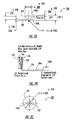
- Figures 2A and 2B illustrate a preferred embodiment of a dual symmetry NMR coil 100.
- the body of the NMR coil 100 includes opposing first and second flange portions 101,102 and a center coil-receiving portion 105a .
- the body is preferably formed of a non-conducting material such as FLUOROSINT 500 .
- Conducting coil 105 is wrapped onto the center coil-receiving portion 105a of the coil body.
- Preferably, about 350 turns of 30 AWG (copper) wire is wrapped along the center coil-receiving portion 105a.
- the conducting coil 105 wire turns can be secured onto the NMR coil body center coil-receiving portion 105a such as with 1 ⁇ 4 inch (6.4 mm) glass tape. It is also preferred that the wire forming the conducting coil 105 be selected to have about a 200°C continuous service rating. This will allow the winding to withstand the operating temperatures inside the oven 122 (typically about 160-200°C). As shown in Figure 2B , the NMR coil 100 also includes a length of wire 106 extending from the coil 100 to connect it to a NMR polarization detection circuit 100D ( Figure 5).
- a first major portion of this wire length 106 is preferably formed as a set leads having a major twisted portion 106A having a twist configuration of about 8 twists per inch (3 twists per cm) and extending with an associated length of about 16 inches (41 cm).
- a minor portion 106B of the two leads 106 is untwisted.
- the minor portion is about two inches in length (less than about 20% of the twisted length).
- the untwisted portion 106B of the leads 106 are stripped and plated with a conductive metal plating such as tin.
- the NMR coil 100 is preferably configured such that the coil spool center receiving portion 105a has about a 0.5 inch (127 cm) diameter with the coil layers winding out the coil 105 to about a 0.85 inch (2.16 cm) (and typically under 1.0 inches (2.54 cm)) diameter.
- the NMR coil 100 is configured to provide a DC resistance of about 7.0 ⁇ 1.0 ⁇ and an inductance of about 2.13 ⁇ 0.2mH.
- the NMR coil 100 is tuned to resonate at about 25kHz which corresponds to a fixed capacitor of about 20,000 pF. This yields a Q value of about 20.
- the first and second flange portions 101,102 have "dual symmetry" with respect to the center coil portion 105a ( i . e ., they are sized and configured the same).
- the dual symmetry configuration of the NMR coil 100 allows the same NMR coil 100 and the same NMR polarization detection circuit 100D to be used to measure the polarization of the gas at two different points in the production cycle, i . e ., at two different locations in the hyperpolarizer unit 10; at the polarizer cell 22 and at the secondary reservoir 120 associated with the gas proximate to the dispensing outlet 50 .
- an upper exposed planar perimeter surface 100a of the first flange portion 101 is positioned to contact the optical cell and the lower exposed perimeter surface 100b of the second flange portion 102 is positioned to contact the secondary reservoir 120 .
- the two flange portions 101, 102 have a relatively small or thin width of less than about 0.1 inches (2.54 mm), and more preferably of less than about 0.063 inches (1.6 mm).
- This small or thin symmetrical flange portion configuration can allow the coil conductive portion 105 to be positioned closer to the hyperpolarized gas on both flange sides 101, 102 of the NMR coil 100.
- the NMR coil 100 is about 0.250 inches in height (about .63cm).
- the NMR coil 100 also includes a center aperture 103 formed therethrough.
- the aperture 103 can be filled or the body formed as a solid non-conductive material in this volume.
- FIG 3 illustrates a preferred embodiment of a secondary reservoir 120 (also descriptively called a post-thaw bulb for cryogenic accumulator applications).
- the secondary reservoir 120 includes an enclosed end portion 121 which is configured to capture the hyperpolarized gas therein.
- the enclosed end portion 121 is positioned to face the adjacently contacting surface of the NMR coil 101b.
- the enclosed end 121 is preferably configured with a thin wall face portion, i.e ., the portion which is configured to contact the NMR coil 100 .
- the enclosed end 121 is formed of PYREX which is about 1-2 mm thick.
- gas contacting surfaces of the secondary reservoir 120 can be coated with surface-relaxation resistant materials or formed from different materials to increase T 1 .
- Metal film surfaces may also be used but care should be taken that they be configured sufficiently thin to preclude signal degradation/strength.
- Figure 3 illustrates the enclosed end portion 121 as a substantially planar face and is preferably configured to rest against the bottom of the NMR coil 100.
- Figure 3A illustrates an alternative configuration for the secondary reservoir 120' which configures the enclosed end 121P with a circumferentially positioned upstanding ridge 121P.
- This ridge is configured and sized to receive the outer diameter of the bottom flange of the NMR coil 100 therein.
- This configuration can provide easy alignment with the coil 100. Precise alignment and reliably repeatable positioning of the NMR coil 100 can improve the accuracy and reproducibility of the calibration across multiple hyperpolarizers during increased production builds and can also facilitate a more repeatable replacement of the coil in the field.
- the secondary reservoir 120 also includes a second end 122 which is configured to attach to the plumbing of the hyperpolarizer unit 10 along the bleed path 115.
- the secondary reservoir 120 also includes a longitudinally extending central portion.
- the secondary reservoir 120 includes a passage 124 which defines a free volume of about 3-4 cubic centimeters and which is open to allow gas to flow through to the enclosed end 121 thereof.
- the bleed line 115 and the secondary reservoir 120 have hyperpolarized gas contacting surfaces, it is preferred that they be configured to minimize contact induced depolarization, i.e. , the walls and valves, O-rings and the like are formed of polarization friendly materials or coatings. See U.S. Patent No. 5,612,103 to Driehuys et. al.
- the secondary reservoir 120 is configured with a body which has a surface induced contact relaxation which is longer than about 10 seconds, more preferably longer than about 30 seconds, and most preferably longer than about 2.0 minutes, to allow sufficient time to collect a NMR signal and obtain a polarization reading.
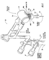
- Figure 4 illustrates a perspective view of a plumbing diagram for a preferred embodiment of a hyperpolarizer unit 10 according to the present invention.
- the NMR coil 100 is positioned adjacent a laterally intermediate bottom portion of the polarizer cell 22 (but can, of course, be alternatively positioned as long as it is within a suitably homogeneous magnetic field).
- the NMR coil 100 is positioned intermediate the polarizer cell 22 on one end and the secondary reservoir cell 120 on the other.
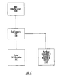
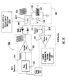
- FIG. 5 illustrates an electrical block diagram layout for a preferred on-board polarization monitoring embodiment for the NMR coil 100 of the present invention.
- a single unitary NMR detection circuit 100D can be employed to monitor the polarization level of the gas via the NMR coil 100 during the production cycle, namely, the polarization level at the optical (polarizer) cell 22P and the polarization level of the polarized gas at the secondary reservoir 120P.
- This configuration allows the same NMR coil, the same circuit and cables to monitor two gas locations.
- This dedicated circuit 100D can eliminate the switching of cables and pulse parameter adjustments needed for operation.
- NMR coils positioned in alternate locations along the production path, such as in a post-accumulation region, a pre-dispensing region, or at a position along the exit flow path 113P in the hyperpolarizer unit 10, one can physically or electrically switch cables or other operational circuitry to look at the desired position (shown for example in Figure 14 as 302S).
- a different NMR circuit may be used to drive a higher frequency excitation pulse as will be discussed further below.
- NMR uses heterodyning or homodyning techniques to mix the received signal with a carrier of similar frequency.
- these techniques give a sum and difference frequency as will be appreciated by those of skill in the art.
- FT Fourier Transformed
- Figure 14 illustrates a suitable prior art NMR detection circuit 100D which has been modified to add a circuit switching means 302S.
- the NMR detection circuit 100D uses a low field spectrometer or transmitter 302T which comprises a power supply 310, a pulse generator 300, and a transmit amplifier 302.
- a transmit/receive line (111) connects the coil 100 to both the transmitter 302T and a receiver 305R.
- the receiver 305R shown includes a receive amplifier 305 and computer 309 and can also include a filter 307.
- the NMR detection circuit 100D also preferably includes diode gates 209 to direct the signal from the transmitter to the coil 100 or from the coil 100 to the receiver portion of the circuit 100D according to the operational mode of the NMR detection circuit.
- the circuit 100D can employ a simple receiver analyzer which includes a peak-to-peak detector which translates the peak detection into a polarization level and a simple display or oscilloscope output (it does not require a computer to evaluate or measure the polarization).
- the NMR detection circuit 100D is configured to avoid the need to mix the received signal. Instead, the received signal is amplified, filtered, and analyzed via FID (free induction decay), directly.
- FID free induction decay
- This direct FID analysis allows a non-complex single channel signal detection and advantageously reduces the complexity of the signal analysis circuitry (no complicated FT's).
- Figure 13 shows a graphic comparison of a direct detection method with a typical mixed-down (two channel FID).
- the original FID frequency is 75.1kHz and the associated T 2 * is 5.16ms.
- the mixed-down FID frequency is 200Hz. Both channels of the mixed-down FID underestimate the peak-to-peak amplitude of the signal.
- the polarization is proportional to the peak-to-peak amplitude of the FID, which can be analyzed using cursors or relatively inexpensive peak detection circuitry.
- numerous cycles occur in the direct-detect mode before attenuation due to T 2 * sets in. Accordingly, this direct-detect method is more accurate over conventional mixed down FID measurements. Further, because of the elimination of the requirement for homodyning, one can operate directly on the coil response resonance which also allows for improved accuracy.
- other polarimetry configurations can be used as is known to those of skill in the art. See e.g. , Saam et al., Low Frequency NMR Polarimeter for Hyperpolarized Gases, Jnl. of Mag. Res., 134, pp. 67-71 (1998).
- the NMR detection circuit 100D employ a hot carrier Shotky diode gate 209 which have a 0.25V conduction voltage.
- This type of diode gate can reduce distortion (standard diode gates in NMR are 1N914A diodes with conduction voltages of about 0.6V). This can also reduce the ring-down time of a NMR coil after excitation to about 0.2 ms, thereby allowing the FID to be sampled about 3.5ms earlier than other monitoring systems for hyperpolarizer units. It is also to be noted that the using a diode gate can introduce signal leakage problems.
- the diode gate 209 includes two diodes connected in parallel with opposite polarities.
- one of the diodes is always in conduction (assuming the voltage is above the diode drop) irrespective of the sign of the voltage. If the voltage is below the diode drop, then both diodes act to block and prevent any signal from passing ( i.e. , act as a gatekeeper).
- the diode gates 209 act to send small signals from the coil 100 (a signal with a voltage which is below the diode voltage drop) to the receiver 305R rather than back into the transmitter 302T. However, during transmittal of the pulse (at voltages much larger than the diode voltage drop), the diode gates 209 act like a conductor to the coil 100.
- the NMR detection circuit 100D preferably employs a single fixed capacitor 230 for tuning a corresponding NMR coil circuit 200.
- NMR coil circuits 200 are typically "tuned” by putting a capacitor “C” in parallel with the excitation coil (which has an associated inductance “L”).
- the coil circuit resonates at a frequency "f” and therefore can enhance response to signals at or near that frequency, while also having reduced response to noise outside of its frequency bandwidth.
- a series/parallel combination of adjustable capacitors are used to tune the circuit to resonance and to have an impedance of 50 Ohms (typically required for high-frequency operation). This type of capacitor configuration can require frequent and careful adjustments to same to ensure a properly tuned circuit.
- a single, high-precision, fixed-value capacitor be used in the NMR detection circuit 100D to tune the NMR coils described herein. This is accomplished by also using the diode gate 209 and low operating frequencies (about 1-400kHz) in the NMR detection circuit 100D.
- Figure 6 illustrates an alternate hyperpolarizer unit 10 with two separate NMR coils 100, 150.
- the second NMR coil 150 is advantageously positioned along the post-polarizer or optical cell flow path 122 or adjacent the cell exit port 22b. This positioning can provide a more reliable level of polarization of the gas as it actually exits the cell 22, rather than the level conventionally monitored by NMR coil's typically mounted beneath the center portion of the optical cell.
- the conventional configuration can give good readings absent flow, during flow, the gas passing over the coil is typically not fully polarized compared to the level it should obtain as it ultimately flows out of the exit port of the optical cell.
- the position of a NMR coil 150 adjacent the polarizer cell outlet 22b can give a NMR signal level commensurate with the flow of the gas as it exits the polarizer cell 22, and, as such, can provide an improved production control measurement parameter for the polarization level of the gas achieved at this process flow point.
- this flow path monitoring can, of course, also be used with batch mode hyperpolarizers (typically used to produce hyperpolarized 3 He). This can allow a convenient NMR coil measurement prior to dispensing but in the gas exit flow path adjacent the polarizer cell 22.
- Figure 7B illustrates a fabrication technique for including such a monitoring coil 150 on the cell exit leg 22b adjacent the major cell body.
- the polarizer cell 22 is typically formed by a skilled molten glass-forming artisan.
- the glass body is formed and then the legs are formed therein to form the optical cell 22.
- the conventional fabrication process can be altered as shown in Figure 7B .
- the glass body 119B is formed and an upper portion of the leg 119L (the upper and lower portions 119L1, 119L2 defining the exit leg 122 ) is formed (blown).
- the NMR coil 150 is slipped over the partially formed leg 119L1 and positioned to extend above the lower portion of the leg 119L2 which includes the expanded section and plumbing attachments 28 to provide the optical cell NMR monitoring coil 150 as shown in Figure 7A .
- the NMR coil 150 can be attached to a cell body at an exit aperture region and a single integral leg 122 can be attached or drawn therethrough (not shown).
- the NMR monitoring coil 150 is preferably configured with a center aperture which is sized to be slightly larger than the outer diameter of the leg 221 so that the NMR coil 150 can be slid over the leg and positioned adjacent the primary body of the optical cell, while also being sized and configured to be held securely thereagainst.
- the glass body 119B and legs 119L1, 119L2 can be formed from PYREX®.
- the body and legs can be formed of materials which are substantially non-paramagnetic and non-conducting such as aluminosilicates and the like.
- the flow of the hyperpolarized gas is temporally stopped or slowed while the polarization measurement signal is obtained in the NMR coil 150 to maintain a sufficient quantity of the polarized gas proximate to the NMR coil 150 while the FID signal is obtained.
- xenon gas is passed at a desired flow rate through the polarizer cell 22 and out of the exit port 22b.
- the valves can be temporarily closed to cease the flow of the polarized gas out of the exit port 22b, receive the NMR signal via the NMR coil on the outlet arm 150, and re-start the flow of the polarized gas.
- This flow interruption time cycle is preferably short, such as under 10 seconds.
- a bleed line (not shown) can also be positioned in fluid communication with the exit port 22b and used to direct a small quantity of the polarized gas to an in-process measurement NMR coil (such as the dual symmetry NMR coil or another separate NMR coil (not shown)) in a homogeneous field region of the hyperpolarizer for a in-process flow reading, thus not requiring the flow to be suspended for a reliable flow path measurement.
- the NMR coil 150 can abut the cell itself and be configured and sized about the cell to provide reliable information about the polarization of the gas as it approaches the cell exit.
- flow path NMR coil configurations can also be used such as other plumbing or valve configurations to direct and capture a sufficient quantity of gas in the flow path to measure the polarization of the gas in the flow path.
- signal information representative of the polarization of the flowing gas can allow for more precise process parameter adjustment (such as in the operation of the optical cell) and real-time process information.
- Figure 6 illustrates the hyperpolarizer 10' with both the NMR monitoring coil 150 and the dual symmetry coil 100
- the present invention is not limited thereto.
- the hyperpolarizer 10' can be alternatively configured with just the outlet arm NMR monitoring coil 150, and/or with the NMR monitoring coil 150 spatially translated to be mounted at a different position along the optical cell exit leg.
- FIG 8 illustrates yet another embodiment of a hyperpolarizer unit 10" according to the present invention.
- the hyperpolarizer unit 10" includes a cryogenic NMR monitoring coil 175.
- this monitoring coil 175 is preferably positioned in the hyperpolarizer unit 10" to monitor the polarization of the collected, i . e ., frozen (iced) polarized gas. Because this monitoring coil 175 can be exposed to extreme conditions (cryogenic temperatures), it is preferred that the NMR monitoring coil 175 be formed of body and wire materials which are suitable for same.
- a suitable wire is a thermoplastic coated copper wire, other suitable materials include Ultem®, Nylatron®, or Torlon® polymers and the like.
- the resistance of the wires at the lower temperatures will be reduced and the NMR detection circuit 100D" is preferably configured to account for temperature-induced variance.
- the lower resistivity of the wire may improve the "Q" of this circuit, but, as will be appreciated by those of skill in the art, the lower resistivity is typically insubstantial when compared to inter-wire capacitance in low-field applications (which dominates the "Q" of the circuit). That is, the NMR coils of the present invention employ numerous windings (typically 100-300) compared to a few turns of wire on a coil for typical high-field applications (where the "Q" can be dominated by wire resistivity).
- the cryogenic NMR monitoring coil 175 can be configured in several ways.
- the NMR coil 175 is configured as a solenoid which is positioned around the collection chamber of the cold finger 30.
- the NMR coil 175 is configured as a solenoid 175a (in contrast to the surface coil type 175b shown in Figure 10) to wrap around a lower portion of the exterior of the cold finger 30 or collection chamber itself.
- the solenoid 175a can be configured and sized to extend and proximate to the exterior of the cold finger such that it is proximate to substantially the entire ice reservoir or holding region of the collection chamber ( i.e. , the region where the frozen gas is positioned).
- the magnetic field source is preferably configured to generate a magnetic field which is transversely oriented (perpendicular or normal) to the direction of the field associated with the pulsing of the corresponding NMR coil. Therefore, the magnetic field source operably associated with the cryogenic NMR coil 175 (whether permanent magnets 40 or electromagnets 40') is configured to generate the appropriately directed magnetic field as well as a sufficient degree of homogeneity for the NMR measurement.
- Figure 9 illustrates the magnetic field source for the cryogenic NMR coil 175 as a set of permanent magnets 40.
- the magnetic field source can also be configured as an electromagnet or solenoid 400 and positioned to be spatially separated with the cold finger 30 intermediate thereof about the lower region of the cold finger which holds the frozen gas.
- the magnitude of the magnetic field source (shown for example as a permanent magnet 40 in Figure 9 and an electro-magnet 400 in Figure 11) is preferably configured to generate a substantially fixed or constant low-level magnetic field of at least about 0.05 T (500 G) so that the resonant frequency of 129 Xe is about 589kHz.
- the NMR coil 175a is configured with an inductance of about 0.24mH or less.
- the measurement or detection circuit is tunable with some amount of variable capacitance to adjust the tuning to match the Larmor frequency of the frozen 129 Xe.
- the cryogen based NMR coil 175a and associated detection circuit is configured with a capacitance which includes a tunable amount of about 0-100pf, and about 100pf due to cabling or wiring, and about a 100 pF fixed capacitor.
- the NMR coil 175a is sized such that it covers (extends about) the entire 129 Xe ice collection region.
- a NMR coil 175a with a winding length of about 2 cm and a radius of about 1 cm may be suitable.
- about 220 turns of wire will provide about 0.24 mH inductance.
- the applied static magnetic field (B 0 ) is oriented to be perpendicular or normal to the NMR coil RF field (B 1 ) provided by the NMR coil.
- B 0 is transverse
- B 1 is axial
- B 0 is axial
- B 1 is transverse
- the axial direction means the direction which is parallel to or collinear with the upright cold finger 30 (shown in position in Figures 10 and 11).
- a pair of opposing ceramic magnets are used as described above and the corresponding B 1 is thus axial and applied via a NMR coil 175a configured as a solenoid.
- an electro-magnet coil 40' (such as a Helmholtz pair) can also be configured to generate a transverse static magnetic field B 0 .
- Another alternative is to use a transversely oriented solenoid for the static field with an axially oriented B 1 associated with the NMR coil 175a as schematically shown in Figure 11.
- Electro-magnet configurations which provide suitable axial fields include a relatively large solenoid for an axial B 0 (such as 20-30 cm long and 10 cm in diameter) and a small solenoid associated with the B 1 of the NMR coil (such as 2 cm long and 2 cm in diameter).
- the typical magnetic field strength surrounding the frozen accumulated polarized gas is provided by a permanent magnet arrangement generating a relatively low field and not particularly homogeneous magnetic field.
- the homogeneity generated thereby is suitable for frozen gas which is not particularly susceptible to magnetic gradients, but unfortunately the permanent magnet arrangement used in the past is generally not homogeneous enough for sensitive and/or precision NMR measurement. See e . g ., U.S. Patent No. 5,809,801 to Cates et al. for more details of the cryogen permanent magnet yoke.
- the permanent magnet arrangement 40' be modified to fit outside the cryogen bath 43.
- the permanent magnet arrangement 40' is sized and configured to produce a magnetic field of from 1-2000 Gauss (1 x 10 -4 T to 0.2 T), more preferably about 50-1000 Gauss (0.005 T to 0.1 T), and still more preferably about 500-1000 Gauss (0.05 T to 0.1 T).
- the magnet field have a homogeneous region sufficient to extend across the lower portion of the cryogenic compartment.
- the homogeneity is sufficiently high so that gradient induced T 2 * is longer than the T 2 of the ice.
- the permanent magnet arrangement 40 is configured with a physically larger magnet assembly relative to that used for the cryogen cold finger accumulation in the past.
- one configuration is to employ about 20cm diameter magnets (disks) with magnet poles which are separated across the dewar or liquid cryogen bath container by a separation distance of about 8 cm which can provide about a 500 Gauss (0.05 T) field with sufficient homogeneity about the desired region.
- a set of discrete permanent magnets 40 are positioned opposing the other across the outer wall of the dewar flask or cryogen bath container 43 such that the diametrically opposed permanent magnets 40 have a diametric separation of about 8 cm (3 in).
- the permanent magnets 40 can be a series of stronger field ceramic magnets (the latter can increase the field strength generated by same).
- the permanent field disk magnets 40 can be aligned by a structural yoke 401 and/or can include a flux return.
- a flux return can increase the field strength of this arrangement while also minimizing interference from stray magnetic flux.
- the flux return can be configured as a soft iron material.
- the magnets 40 can themselves be secured to the outside wall of the cryogen container or flask 42 holding the cryogen bath 42 or otherwise supported to provide the desired spatial separation and alignment.
- other magnet geometry configurations can be used to provide a suitable magnetic field strength and homogeneity.
- Figure 10 also illustrates an accumulator and magnet assembly 230.
- the accumulator 30 is supported by a support platform 210 positioned over the cryogen bath 43.
- the magnets are separated a distance "D" and positioned external to the cyrogen bath 43.
- the separation distance "D" is at least about 8 cm for a magnet disk having about a 20 cm diameter.
- a pair of plates 215 longitudinally extend from the support platform 210 and connect to the bottom of the holding assembly 275 which is sized to hold the NMR coil 175b to contact the bottom of the collection reservoir 75 of the accumulator 30 to provide the desired magnetic field to the collected polarized gas.
- the accumulator 30 includes a support contact portion 211, which is configured to rest against the support platform 210 and has a lateral support member 215a which extends to hold the top portion of the collection reservoir 75.
- the accumulator 30 is preferably immersed in the cryogen bath 43 such that the reservoir 75 and about 3-6 inches (7.5-15 cm) of the tube are immersed. If submerged in liquid nitrogen, the exterior wall of the outer sleeve 103 and the exterior wall or the reservoir 75 will be at about 77°K. The freezing point.of xenon is approximately 160°K.
- the hyperpolarized gas hits the cold surface and freezes into the reservoir 75 while the buffer gases exit the accumulator via an exit channel 90 (not shown).
- the reservoir 75 can include a surface coating to help prevent relaxation caused by the polarized gas's contact with same.
- Figure 11 illustrates the NMR coil 175c alternatively configured and positioned as a solenoid type excitation coil which extends about the length "L" of the accumulation bulb or reservoir 75 and is preferably configured to contact or extend in close proximity to the exterior of same (a cryogen immersed portion) of the reservoir 75.
- Figure 9 illustrates a hyperpolarizer unit 10"' with a multi-point polarization monitoring system.
- This embodiment includes the first NMR coil 100 positioned adjacent the optical cell 22 and secondary reservoir 120, the second NMR monitoring coil 150 positioned adjacent the optical cell exit 22, and the third cryogenic NMR monitoring coil 175 positioned to monitor the polarization of the frozen gas.
- Figure 9 also illustrates an evacuated bag or vessel 525 attached to the dispensing outlet 50 and the secondary flow path 115 in fluid communication with the exiting gas flow path proximate the gas dispensing port 50.
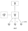
- Figure 12 schematically illustrates a hyperpolarizer detection circuit for a multi-NMR coil monitoring system.
- the instant multi- or dual-polarization monitoring method can also successfully be employed on a hyperpolarizer used with other hyperpolarized noble gases such as 3 He.
- the NMR coils 100, 125, 175 of the instant invention are high precision NMR coils. That is, it is preferred that the NMR coils are designed and produced in a reliable and substantially consistent manner (such as to controlled tolerance and controlled manufacturing processes, preferably to six sigma production standards). This allows the hyperpolarizer to establish a calibration standard which is substantially the same for a particular position on the hyperpolarizer across replacement modules.
- a "T 1 " decay constant associated with the hyperpolarized gas' longitudinal relaxation time is often used to describe the length of time it takes a gas sample to depolarize in a given situation.
- the handling of the hyperpolarized gas is critical because of the sensitivity of the hyperpolarized state to environmental and handling factors and the potential for undesirable decay of the gas from its hyperpolarized state prior to the planned end use, i . e ., delivery to a patient for imaging.
- Processing, transporting, and storing the hyperpolarized gases -- as well as delivering the gas to the patient or end user -- can expose the hyperpolarized gases to various relaxation mechanisms such as magnetic gradients, contact-induced relaxation, hyperpolarized gas atom interactions with other nuclei, paramagnetic impurities, and the like.
- a selected RF excitation pulse (of predetermined frequency, amplitude, and duration) is transmitted from a pulse generator 300 via an amplifier 302 through a set of diode gates 209 to the surface coil 100.
- the transmitted excitation pulse locally excites the hyperpolarized gas (or frozen gas) sample 250.
- the circuit 100D may include a switching means 302S (electrical, mechanical, or program/software directed switches) to switch between the differently located detection coils in the production cycle.
- Alternatively or in addition to the switching means 302S for high-frequency ice measurements an alternate transmitter 302T circuit may be employed.
- an alternate receiver circuit or additional components associated therewith can also be employed (not shown).
- the hyperpolarized gas 250 responds to the excitation pulse inducing a response signal back to the receiver 305R through an amplifier 305 (optionally filtered) and then to the a computer driven interrogation signal analyzer 309.
- a response signal is received corresponding to the response of the gas to the excitation pulse.
- the received signal is analyzed (preferably peak to peak, direct FID detection) to determine the polarization of the hyperpolarized gas.
- the relatively non-complex analysis does not require a computer or complex signal processor, but can instead employ a peak detector analysis circuit.
- the excitation pulse is a RF pulse having a selected pulse time and frequency which corresponds to the strength of the magnetic field and the particular hyperpolarized gas.
- frequencies used for 3 He gas phase are about 75kHz (with a static magnetic field of about 2.34 x 10 -3 T (23.4 G)) or more (with an associated change in the magnetic field strength).
- An alternative preferred frequency is about 24kHz with the frequency for gaseous 129 Xe also being preferably about 24kHz (with the frozen phase frequency being increased, i . e ., being a higher frequency than the gas excitation pulse frequency).
- 24kHz can be used for both 129 Xe and 3 He.
- the magnetic field used for 3 He is typically smaller at a similar frequency.
- about a 2x10 -3 (2.04 ⁇ 10 -3 )T) (20 (20.4) G) field is preferably used for 129 Xe while about a 7x10 -4 (7.5x10 -4 ) T (7 (7.5) G) field is used for 3 He.
- the 129 Xe resonance frequency is proportional to field strength by the known ratio of 1.18kHz/G; thus, as noted, for a 2x10 -3 T (20 G) field, the frequency is about 24kHz while for a 0.05 T (500 G) field a suitable frequency for gaseous xenon is about 600kHz.
- the higher detection frequency preferably used for the 129 Xe ice (frozen phase gas) is related to the fact that T 1 is longer at 5x10 -2 T (500G).
- the NMR detection circuit 100D ( Figure 12) is preferably configured to transmit a first pulse at a first frequency (f 1 ) for the NMR coils 100,125 and a second higher frequency (f 2 ) for the ice-positioned NMR coil 175.
- the RF pulse generates an oscillating magnetic field which misaligns a small fraction of the hyperpolarized gas (i.e ., 3 He or 129 Xe) nuclei from their static magnetic field alignment position.
- the misaligned nuclei start precessing at their associated Larmour frequency (corresponding to pulse frequency).
- the precessing spins induce a voltage in the NMR surface coil 100.
- the voltage is received back (typically amplified) and the signal is a FID signal.
- the initial peak-to-peak voltage of this signal is directly proportional to polarization (using a known calibration constant). Saam et al. includes more discussion on one way to establish calibration standards. See Saam et al., supra .
- each of the NMR coil embodiments 100, 150, 175 described herein include an input/output line such as single coaxial signal line (handles both the transmit/receive signal) 111 ( Figure 8) which is operably associated with the transmitter 302T and receiver 302R portions of the detection circuit 100D ( Figure 14).
- the pulse generator 309 will preferably be configured to provide an increased signal frequency for the ice and operate recognizing that the T 2 * of the ice will be decreased over that of the gas.
- the excitation pulse of the instant invention is selected such that it can reliably determine the level of polarization while minimally depolarizing the gas.
- the optimal pulse voltage depends on several factors.
- the NMR coil 175a is configured to encompass substantially all of the collected frozen (ice phase) hyperpolarized gas in the cold finger 30.
- a plurality of pulses with extremely small flip angles are used to excite the frozen gas.
- "extremely small” means pulse angles of less than about 5 degrees, and preferably in the range of about 1-2 degrees. The extremely small pulse flip angles minimize the depolarizing effect of the signal measurement on the gas/ice. This is attributed to the relationship between the flip angle associated with the excitation pulse and the retained polarization.
- the signal per pulse flip angle is proportional to the sine of the pulse angle (theta), while the retained magnetization is proportional to the cosine of the pulse flip angle (theta).
- the cosine of theta is 0.994. Therefore, even if ten (2) degree flip angle pulses were taken of the sample, this should leave the sample with about 99.3% of the original magnetization and minimally affect the original signal strength associated with the unmeasured polarization of the hyperpolarized frozen gas.
Landscapes
- Physics & Mathematics (AREA)
- Condensed Matter Physics & Semiconductors (AREA)
- General Physics & Mathematics (AREA)
- Magnetic Resonance Imaging Apparatus (AREA)
- Investigating Or Analysing Materials By Optical Means (AREA)
Abstract
Description
- The present invention relates to the collection and accumulation of polarized noble gases, and relates more particularly to the determination of the level of polarization of hyperpolarized gases used in NMR and magnetic resonance imaging ("MRI") applications.
- It has recently been discovered that polarized inert noble gases can produce improved MRI images of certain areas and regions of the body which have heretofore produced less than satisfactory images in this modality. Polarized helium-3 ("3He") and xenon-129 ("129Xe") have been found to be particularly suited for this purpose. Unfortunately, as will be discussed further below, the polarized state of the gases are sensitive to handling and environmental conditions and can, undesirably, decay from the polarized state relatively quickly. Further, because of the sensitivity of the polarized gas, it is desirable to monitor the polarization level of the gas at various times during the product's life. For example, in-process monitoring can indicate the polarization achieved during the optical pumping process (described below) or the polarization lost at certain phases of the life cycle process (so as to determine the remaining useable life of the polarized gas or to help identify critical production path issues).
- Hyperpolarizers are used to produce and accumulate polarized noble gases. Hyperpolarizes artificially enhance the polarization of certain noble gas nuclei (such as 129Xe or 3He) over the natural or equilibrium levels, i.e., the Boltzmann polarization. Such an increase is desirable because it enhances and increases the MRI signal intensity, allowing physicians to obtain better images of the substance in the body. See U. S. Patent No. 5,545,396 to Albert et al.
- In order to produce the hyperpolarized gas, the noble gas is typically blended with optically pumped alkali metal vapors such as rubidium ("Rb"). These optically pumped metal vapors collide with the nuclei of the noble gas and hyperpolarize the noble gas through a phenomenon known as "spin-exchange." The "optical pumping" of the alkali metal vapor is produced by irradiating the alkali-metal vapor with circularly polarized light at the wavelength of the first principal resonance for the alkali metal (e.g., 795 nm for Rb). Generally stated, the ground state atoms become excited, then subsequently decay back to the ground state. Under a modest magnetic field (10-3 T (10 Gauss)), the cycling of atoms between the ground and excited states can yield nearly 100% polarization of the atoms in a few microseconds. This polarization is generally carried by the lone valence electron characteristics of the alkali metal. In the presence of non-zero nuclear spin noble gases, the alkali-metal vapor atoms can collide with the noble gas atoms in a manner in which the polarization of the valence electrons is transferred to the noble-gas nuclei through a mutual spin flip "spin-exchange."
- In any event, after the spin-exchange has been completed, the hyperpolarized gas is separated from the alkali metal prior to introduction into a patient (to form a non-toxic pharmaceutically acceptable product). Unfortunately, both during and after collection, the hyperpolarized gas can deteriorate or decay relatively quickly (lose its hyperpolarized state) and therefore must be handled, collected, transported, and stored carefully. Thus, handling of the hyperpolarized gases is critical, because of the sensitivity of the hyperpolarized state to environmental and handling factors and the potential for undesirable decay of the gas from its hyperpolarized state.
- Some accumulation systems employ cryogenic accumulators to separate the buffer gas from the polarized gas and to freeze the collected polarized gas. to Driehuys et.
- Conventionally, the level of polarization has been monitored at the polarization transfer process point (i.e., at the polarizer or optical cell) in a hyperpolarizer device or measured at a site remote from the hyperpolarizer after the polarized gas is dispensed from the hyperpolarizer (see, e.g., US-A-5 642 625 disclosing a hyperpolarizer according to the preamble of claim 1). For example, for the latter, the polarized gas is directed to an exit or dispensing port on the hyperpolarizer and into two separate sealable containers, a gas delivery container, such as a bag, and a small (about 5 cubic centimeter) sealable glass bulb specimen container. This glass bulb specimen container is then sealed at the hyperpolarizer site and then carried away from the hyperpolarizer to a remotely located high-field NMR spectroscopy unit (4.7T) to determine the level of polarization achieved during the polarization process. See J.P. Mugler, B. Driehuys, J.R. Brookeman et al., MR Imaging and Spectroscopy Using Hyperpolarized 129Xe Gas; Preliminary Human Results, Mag. Reson. Med. 37, 809-815 (1997).
- Generally stated, as noted above, conventional hyperpolarizers may also monitor the polarization level achieved at the polarization transfer process point, i.e., at the optical cell or optical pumping chamber. In order to do so, typically a small "surface" NMR coil is positioned adjacent the optical pumping chamber to excite and detect the gas therein and thus monitor the level of polarization of the gas during the polarization-transfer process. The small surface NMR coil will sample a smaller volume of the proximate polarized gas and thus have a longer transverse relaxation time (T2*) compared to larger NMR coil configurations. A relatively large tip angle pulse can be used to sample the local-spin polarization. The large angle pulse will generally destroy the local polarization, but because the sampled volume is small compared to the total size of the container, it will not substantially affect the overall polarization of the gas.
- Typically, the surface NMR coil is operably associated with low-field NMR detection equipment which is used to operate the NMR coil and to analyze the detected signals. Examples of low-field NMR detection equipment used to monitor polarization at the optical cell and to record and analyze the NMR signals associated therewith include low-field spectrometers using frequency synthesizers, lock-in amplifiers, audio power amplifiers, and the like, as well as computers.
- In any event, it is now known that on-board hyperpolarizer monitoring equipment no longer requires high-field NMR equipment, but instead can use low-field detection techniques to perform polarization monitoring for the optical cell at much lower field strengths (e.g., 10-4-10-2 T (1-100G)) than conventional high-field NMR techniques. This lower field strength allows correspondingly lower detection equipment operating frequencies, such as 1-400kHz.
- For applications where the entire hyperpolarized gas sample can be located inside the NMR coil, an adiabatic fast passage ("AFP") technique has been used to monitor the polarization of the gas in this type of situation. Unfortunately, in most production-oriented situations, this technique is not desirable. For example, in order to measure the polarization in a one-liter patient dose bag, a relatively large NMR coil and spatially large magnetic field is needed.
- More recently, Saam et al. has proposed a low-frequency NMR circuit expressly for the on-board detection of polarization levels for hyperpolarized 3He at the optical cell inside the temperature-regulated oven which encloses the cell. See Saam et al., Low Frequency NMR Polarimeter for Hyperpolarized Gases, Jnl. of Magnetic Resonance 134, 67-71 (1998). Magnetic Imaging Technologies, Inc. ("MITI") and others have used low-field NMR apparatus for on-board polarization measurement.
- However, there remains a need to be able to efficiently and reliably determine and/or monitor the level of polarization of polarized gases in various points in the production cycle. This is particularly important for the flowing production modality used for cryogenically accumulated 129Xe, which as noted above, is frozen and thawed during the production cycle.
- In view of the foregoing, it is an object of the present invention to provide methods and apparatus to efficiently monitor the hyperpolarization level of a quantity of hyperpolarized gas at various points in the production cycle.
- It is an additional object of the present invention to provide a hyperpolarizer with means to monitor the polarization level of cryogenically accumulated hyperpolarized gas both before the gas is frozen and after the gas is thawed.
- It is another object of the present invention to provide a method and device for monitoring the polarization level of flowing hyperpolarized gas which can be used in a substantially continuous gas-flow production environment.
- It is a further object of the present invention to provide an apparatus and method which reduces the complexity and number of components needed to monitor the level of polarization in the polarized gas both during the optical pumping process and subsequent to the optical pumping process.
- It is still another object of the present invention to provide an apparatus to monitor the polarization level of frozen polarized gas.
- It is an additional object of the present invention to provide an apparatus that can improve the predictability of a cryogenic hyperpolarized gas production process.
- It is a still further object of the present invention to provide an apparatus that can reliably yield sufficient levels of polarized gas during post accumulation thaw.
- These and other objects are satisfied by the present invention by a hyperpolarizer as defined in claim 1.
- In particular, a first aspect of the invention is directed to a hyperpolarizer for producing polarized noble gases. The hyperpolarizer comprises an optical pumping cell having a non-polarized gas inlet port and a polarized gas outlet port and a magnetic field source operably associated with the optical pumping cell. The magnetic field source is configured to provide a region of homogeneity. The hyperpolarizer also includes a NMR coil having first and second opposing ends. The first end is positioned adjacent the optical pumping cell within the region of homogeneity. The hyperpolarizer also includes a cryogenic accumulator in fluid communication with the optical pumping cell outlet port and a polarized gas dispensing port in fluid communication with the cryogenic accumulator. A polarized gas exit flow path extends between said cryogenic accumulator and the polarized gas dispensing outlet and a secondary reservoir is positioned adjacent the NMR coil second end in fluid communication with the polarized gas exit flow path. During operation of the hyperpolarizer, the NMR coil is configured to excite one of a quantity of polarized gas positioned in the optical cell and a quantity of polarized gas positioned in the secondary reservoir. Preferably, the NMR coil primarily monitors the polarization in the optical cell during operation of the cell, but during post-thaw, the polarization in the optical cell is gone and the only measurable signal will arise from the polarized gas in the post thaw bulb.
- In a preferred embodiment, the magnetic field source defines a region of homogeneity which includes a portion of the optical pumping cell and a (spatial) volume which extends a distance below the optical pumping cell. The NMR coil is positioned on a bottom portion of the optical pumping cell, and the NMR coil and at least a portion of the secondary reservoir are positioned within the region of homogeneity.
- A preferred method of operating an NMR coil positioned proximate to the optical cell outlet port, includes flowing the hyperpolarized gas through the optical cell and out the port at a desired rate. The hyperpolarized gas flow is preferably temporally stopped or slowed and a NMR signal is taken via the coil on the outlet port (or arm) and the flow is then resumed. This configuration and method can generate a signal which is representative of the flowing hyperpolarized gas as it exits the optical cell.
- Yet another aspect of the present invention is a method for monitoring the polarization level of polarized gas during production, as defined in claim 9.
- In a preferred embodiment, the optical pumping chamber has a primary body portion and a polarized gas exit port defined by a longitudinally extending leg, and the NMR excitation coil is positioned around the leg adjacent the primary body portion of the optical pumping chamber. It is also preferred that the method further comprise cryogenically accumulating the polarized gas in a cryogenic accumulator during which a portion of the polarized gas is frozen and then subsequently thawing the frozen polarized gas prior to the dispensing step and after the thawing step. It is also preferred that during or after the thawing step, a minor portion of the quantity of thawed polarized gas is directed away from a major portion of the hyperpolarized gas into the gas flow path proximate to the NMR coil.
- Advantageously, the present invention can monitor the polarization during production and even at the dispensing port where convenient MRI patient-sized quantities (such as 0.5-2 liters of polarized gas) are directed out of the hyperpolarizer. As such, the polarization level at shipping or before storage is readily identifiable before the container is detachably released from the hyperpolarizer unit for easy transport to a remote site. The improved on-board in-process polarization monitoring can improve production and conveniently indicate the level of polarization of gas at several key points including at the dispensing port. Further, the dual symmetry NMR coil can allow a single NMR coil to measure polarization both at the optical cell during the optical pumping process and at a second point in the production cycle, such as at a post-thaw position. Further, the instant invention now configures a cold finger to release cryogenically accumulated hyperpolarized xenon dependent on a more predictable indicator, pressure. Because the release of the thawed gas at a predetermined pressure is less dependent on process variations such as flow rates and collected quantities of gas, a more predictable process can be obtained, thereby providing a more reliably controllable production capability.
- The foregoing and other objects and aspects of the present invention are explained in detail herein.
-
- Figure 1 is a schematic illustration of a hyperpolarizer apparatus according to one embodiment of the present invention.
- Figure 2A is a side view of a dual symmetry NMR coil.
- Figure 2B is a side view of the NMR coil of Figure 2A schematically illustrating the electrical wire wrapped around and positioned onto the NMR coil body.
- Figure 2C is a top view of Figure 2A.
- Figure 3 is an enlarged perspective view of a secondary reservoir.
- Figure 3A is an enlarged perspective view of an alternate embodiment of a secondary reservoir.
- Figure 4 is a perspective view of a partial plumbing layout for a hyperpolarizer with a NMR coil and secondary reservoir according to the present invention.
- Figure 5 is a schematic diagram for an operational relationship of an electrical monitoring circuit according to the present invention.
- Figure 6 is a schematic illustration of an alternate embodiment of a hyperpolarizer with multiple in process polarization monitoring points according to the present invention.
- Figure 7A is a front view of an optical cell and NMR coil illustrating the NMR coil positioned along the exit gas flow path of the optical cell.
- Figure 7B is an exploded view of the optical cell and NMR coil of Figure 7A illustrating a fabrication method for positioning a NMR monitoring coil along the exit flow path of the hyperpolarizer of Figure 6.
- Figure 8 is a schematic illustration of yet another embodiment of a hyperpolarizer with multi-point monitoring according to the present invention.
- Figure 9 is a schematic illustration of an additional embodiment of a hyperpolarizer according to the present invention illustrating a cryogenically positioned NMR excitation coil.
- Figure 9A is an enlarged schematic illustration of the NMR coil configured as a solenoid coil as shown in Figure 9.
- Figure 10 is a schematic side section view of a cryogenically positioned NMR surface coil and externally positioned permanent magnets (i.e., permanent magnets positioned on external to the cryogen bath).
- Figure 11 is a schematic illustration of a front view of a static magnetic holding field applied to an electromagnet or solenoid coil at the cold finger.
- Figure 12 is a schematic illustration of an electric circuit for a hyperpolarizer with multi-NMR coils according to the present invention.
- Figure 13 is a graph illustrating prior art detection methods showing a comparison of a direct-detect FID with a typical mixed-down two channel FID.
- Figure 14 is a schematic illustration of a prior art NMR polarization level detection circuit modified to add a circuit switching means to monitor additional points in the production cycle.
- The present invention will now be described more fully hereinafter with reference to the accompanying figures, in which preferred embodiments of the invention are shown. This invention may, however, be embodied in many different forms and should not be construed as limited to the embodiments set forth herein. Like numbers refer to like elements throughout. In the drawings, layers, regions, or components may be exaggerated for clarity.
- In the description of the present invention that follows, certain terms are employed to refer to the positional relationship of certain structures relative to other structures. As used herein the term "forward" and derivatives thereof refer to the general direction the gas mixture travels as it moves through the hyperpolarizer unit; this term is meant to be synonymous with the term "downstream" which is often used in manufacturing environments to indicate that certain material being acted upon is farther along in the manufacturing process than other material. Conversely, the terms "rearward" and "upstream" and derivatives thereof refer to the directions opposite, respectively, the forward and downstream directions. Also, as described herein, polarized gases are collected, frozen, thawed, and used in MRI applications. For ease of description, the term "frozen polarized gas" means that the polarized gas has been frozen into a solid state. The term "liquid polarized gas" means that the polarized gas has been or is being liquefied into a liquid state. Thus, although each term includes the word "gas," this word is used to name and descriptively track the gas which is produced via a hyperpolarizer to obtain a polarized "gas" product. Thus, as used herein, the term "gas" has been used in certain places to descriptively indicate a hyperpolarized noble gas product and may be used with modifiers such as solid, frozen, and liquid to describe the state or phase of that product.
- Various techniques have been employed to accumulate and capture polarized gases. For example, U.S. Patent No. 5,642,625 to Cates et al. describes a high volume hyperpolarizer for spin polarized noble gas and U.S. Patent No. 5,809,801 to Cates et al. describes a cryogenic accumulator for spin-polarized 129Xe.
- As used herein, the terms "hyperpolarize," "polarize," and the like, mean to artificially enhance the polarization of certain noble gas nuclei over the natural or equilibrium levels. Such an increase is desirable because it allows stronger imaging signals corresponding to better MRI images of the substance and a targeted area of the body. As is known by those of skill in the art, hyperpolarization can be induced by spin-exchange with an optically pumped alkali-metal vapor or alternatively by metastability exchange. See Albert et al., U.S. Patent No. 5,545,396.
- Referring to the drawings, Figure 1 illustrates a
preferred hyperpolarizer unit 10. This is a high-volume unit which is configured to produce and accumulate spin-polarized noble gases substantially continually, i.e., the flow of gas through the optical cell is substantially continuous during accumulation. As shown, theunit 10 includes a noblegas mixture supply 12 and asupply regulator 14. Apurifier 16 is positioned in the line to remove impurities such as water vapor from the system as will be discussed further below. Thehyperpolarizer unit 10 also includes aflow meter 18 and aninlet valve 20 positioned upstream of a polarizer oroptical cell 22. An optic light source such as a laser 26 (preferably a diode laser array) is directed into thepolarizer cell 22 through various focusing and light distributingmeans 24, such as lenses, mirrors, and the like. Thelaser 26 is circularly polarized to optically pump alkali metals in thecell 22. Thecell 22 is positioned inside a temperature-regulated oven (schematically illustrated by a double dotted line) 122. Anadditional valve 28 is positioned downstream of thepolarizer cell 22. - Next in line, as shown in Figure 1, is a cold finger or
accumulator 30. Theaccumulator 30 is connected to thehyperpolarizer unit 10 by a pair of releasable mechanisms such as threaded members orquick disconnects accumulator 30 to be easily detached, removed, or added, to and from thesystem 10. Theaccumulator 30 is operably associated with a cold source or refrigeration means 42. Preferably, and as shown, thecold source 42 is aliquid cryogen bath 43. Theaccumulator 30 will be discussed in more detail hereinbelow. - As shown in Figures 1 and 9, the
hyperpolarizer 10 also includes avacuum pump 60 is in communication with the system. Additional valves to control flow and direct exit gas are shown at various points (shown as 52, 55). A shut-offvalve 47 is positioned adjacent an "on-board"exit gas tap 50. Certain of the valves downstream of theaccumulator 30 are used for "on-board" thawing and delivery of the collected polarized gas as will be described further below. - The
unit 10 also includes adigital pressure transducer 54 and flow control means 57 along with a shut-offvalve 58. The shut-offvalve 58 preferably controls the flow of gas through theentire unit 10; it is used to turn the gas flow on and off, as will be described below. As will be understood by those of skill in the art, other flow control mechanisms, and devices (analog and electronic) may be used within the scope of the present invention. - In operation, a gas mixture is introduced into the
unit 10 at thegas source 12. As shown in Figure 1, thesource 12 is a pressurized gas tank which holds a pre-mixed gas mixture. Generally described, for spin-exchange optically pumped systems, a gas mixture is introduced into the hyperpolarizer apparatus upstream of thepolarizer cell 22. Most xenon gas mixtures include a buffer gas as well as a lean amount of the gas targeted for hyperpolarization and are preferably produced in a continuous flow system. For example, for producing hyperpolarized 129Xe, the pre-mixed gas mixture is about 85-98% He (preferably about 85-89% He), about 5% or less 129Xe, and about 1-10% N2 (preferably about 6-10%). In contrast, for producing hyperpolarized 3He, a typical mixture of about 99.25% 3He and 0.75% N2 is pressurized to 8 atm (0.81 MPa) or more and heated and exposed to the optical laser light source, typically in a batch mode system. In any event, once the hyperpolarized gas exits the polarizer cell (i.e., the pumping chamber) 22, it is directed to a collection or accumulation container. - Thus, as described above, in a preferred embodiment, the pre-mixed gas mixture includes a lean noble gas (the gas to be hyperpolarized) and buffer gas mixture. The gas mixture is passed through the
purifier 16 and introduced into thepolarizer cell 22. Thevalves polarizer cell 22. Thegas regulator 14 preferably steps down the pressure from the gas tank source 12 (typically operating at 2000 psi or 136 atm (13.8 MPa)) to about 6-10 atm (0.61-1.01 MPa) for the system. Thus, during accumulation, the entire manifold (conduit, polarized cell, accumulator, etc.) is pressurized to the cell pressure (about 6-10 atm (0.61-1.01 MPa)). The flow in theunit 10 is activated by openingvalve 58 and is controlled by adjusting the flow control means 57. - The typical residence time of the gas in the
cell 22 is about 10-30 seconds; i.e., it takes on the order of 10-30 seconds for the gas mixture to be hyperpolarized while moving through thecell 22. The gas mixture is preferably introduced into thecell 22 at a pressure of about 6-10 atm (0.61-1.01 MPa). Of course, as is known to those of skill in the art, with hardware capable of operating at increased pressures, operating pressures of above 10 atm (1.01 MPa), such as about 20-30 atm (2.01-3.04 MPa), are preferred to pressure broaden the alkali metal (such as rubidium ("Rb")) and facilitate the absorption of (approaching up to 100%) of the optical light. In contrast, for laser linewidths less than conventional linewidths, lower pressures can be employed. Thepolarizer cell 22 is a high pressure optical pumping cell housed in a heated chamber with apertures configured to allow entry of the laser emitted light. Preferably, thehyperpolarizer unit 10 hyperpolarizes a selected noble gas such as 129Xe (or 3He) via a conventional spin-exchange process. A vaporized alkali metal such as Rb is introduced into thepolarizer cell 22. The Rb vapor is optically pumped via an opticlight source 26, preferably a diode laser. - The
unit 10 employs helium buffer gas to pressure broaden the Rb vapor absorption bandwidth. The selection of a buffer gas is important because the buffer gas - while broadening the absorption bandwidth - can also undesirably impact the alkali metal-noble gas spin-exchange by potentially introducing an angular momentum loss of the alkali metal to the buffer gas rather than to the noble gas as desired. In a preferred embodiment, 129Xe is hyperpolarized through spin exchange with the optically pumped Rb vapor. It is also preferred that theunit 10 use a helium buffer gas with a pressure many times greater than the 129Xe pressure for pressure broadening in a manner which minimizes Rb spin destruction. - As will be appreciated by those of skill in the art, Rb is reactive with H2O. Therefore, any water or water vapor introduced into the
polarizer cell 22 can cause the Rb to lose laser absorption and decrease the amount or efficiency of the spin-exchange in thepolarizer cell 22. Thus, as an additional precaution, an extra filter or purifier (not shown) can be positioned before the inlet of thepolarizer cell 22 with extra surface area to remove even additional amounts of this undesirable impurity in order to further increase the efficiency of the polarizer. - Hyperpolariaed gas, together with the buffer gas mixture, exits the
polarizer cell 22 and enters acollection reservoir 75 located at the bottom of theaccumulator 30. In operation, at the lower portion of theaccumulator 30, the hyperpolarized gas is exposed to temperatures below its freezing point and collected as afrozen product 100 in thereservoir 75. The hyperpolarized gas is collected (as well as stored, transported, and preferably thawed) in the presence of a magnetic field, generally on the order of at least 500 Gauss (0.05 Tesla), and typically about 2kilo Gauss (0.2 Tesla), although higher fields can be used. Lower fields can potentially undesirably increase the relaxation rate or decrease the relaxation time of the polarized gas. As shown in Figure 1, the magnetic field is provided bypermanent magnets 40 positioned in the cryogen bath and arranged about amagnetic yoke 41. - The
hyperpolarizer unit 10 can also capitalize on the temperature change in the outlet line between theheated pumping cell 22 and the refrigerated cold trap oraccumulator 30 to precipitate the alkali metal from the polarized gas stream in the conduit above theaccumulator 30. As will be appreciated by one of skill in the art, the alkali metal can precipitate out of the gas stream at temperatures of about 40°C. Theunit 10 can also include an alkali metal reflux condenser (not shown) or post-cell filter (not shown). The refluxing condenser employs a vertical refluxing outlet pipe which is kept at room temperature. The gas flow velocity through the refluxing pipe and the size of the refluxing outlet pipe is such that the alkali metal vapor condenses and drips back into the pumping cell by gravitational force. Alternatively, a Rb filter can be used to remove excess Rb from the hyperpolarized gas prior to collection or accumulation. In any event, it is desirable to remove alkali metal prior to delivering polarized gas to a patient to provide a non-toxic, sterile, or pharmaceutically acceptable substance (i.e., one that is suitable for in vivo administration). - Once a desired amount of hyperpolarized gas has been collected in the
accumulator 30, theaccumulator 30 can be detached or isolated from theunit 10. In a preferred embodiment,valve 28 is closed, leaving thecell 22 pressurized. This allows theaccumulator 30 and the downstream plumbing to begin to depressurize because theflow valve 58 is open. Preferably, the portion of theunit 10 downstream of thevalve 28 is allowed to depressurize to about 1.5 atm before theflow valve 58 is closed. After closing theflow valve 58,valve 55 can be opened to evacuate the remaining gas in the manifold. Once the outlet plumbing is evacuated,valves accumulator 30 from theunit 10, a receptacle such as abag 525 or other vessel as shown in Figure 9, can be attached to theoutlet 50. Thevalve 47 can be opened to evacuate the attached bag. Once thebag 525 is evacuated and the gas is ready to thaw,valve 52 can be optionally closed. This minimizes the contact of the polarized gas with thepressure transducer region 59 of theunit 10. This region can include materials that have a depolarizing effect on the polarized gas. Thus, long contact times with this region may promote relaxation of the polarized gas. - If the
valve 52 is not closed, thenvalve 55 is preferably closed to prevent the evacuation of polarized thawed gases. It is also preferred that the flow channels on the downstream side of the cell 22 (including the secondary reservoir and bleed line discussed below) are formed from materials which minimize the contact-induced depolarization effect on the polarized state of the gas. Coatings can also be used such as those described in U.S. Patent No. 5,612,103. - In the "on-board" thaw operation,
valve 37 is opened to let the gas out. It then proceeds throughvalve 47 and outoutlet 50. - In the "detached" or "transported accumulator" thaw mode, accumulator first and
second isolation valves accumulator 30. Evacuating theaccumulator 30 allows any residual gas in theaccumulator 30 to be removed. Leaving gas in theaccumulator 30 with the frozen polarized gas may contribute to the heat load on the frozen gas, possibly raising the temperature of the frozen gas and potentially shortening the relaxation time. Thus, in a preferred embodiment, after depressurization and evacuation and closing theisolation valves accumulator 30 is disconnected from theunit 10 via release points 31, 32. - The
isolation valves unit 10 and the environment. After the filledaccumulator 30 is removed, anotheraccumulator 30 can be easily and relatively quickly attached to the release points 31, 32. Preferably, when attaching thenew accumulator 30, the outlet manifold is evacuated using valve 55 (withvalves valve 55 is closed.Valve 28 is then re-opened which repressurizes the outlet manifold to the operating cell pressure.Valve 58 is then opened to resume flow in theunit 10. Preferably, once flow resumes, liquid nitrogen is applied to theaccumulator 30 to continue collection of the hyperpolarized gas. Typically such a changeover takes on the order of less than about five minutes. Thus, apreferred hyperpolarizer unit 10 is configured to provide a continuous flow of hyperpolarized 129Xe gas for continuous production and accumulation of same. - In prior polarization units, typically a NMR excitation coil was positioned in the
oven 122 adjacent the optical cell 22 (also in the oven) to determine the polarization level achieved by the gas in thecell 22. Further, at least one laboratory has also used a small sealable (about 5cc) glass bulb which was filled with a sample of hyperpolarized gas at the same point as the collection vessel or dose bag. The small bulb was then taken to a separate 4.7T spectrometer to determine the level of polarization associated with the collection vessel. - The present invention now conveniently provides for an on-board (on the hyperpolarizer unit 10) polarization level measurement associated with the polarized gas at various points in the production cycle, such as at both at the
polarizer cell 22 and one or more pre-dispensing and post-thaw gas production point(s). As shown in Figure 1, in a preferred embodiment, the (post-thaw) gas exit path 113 (the gas exit path illustrated in dotted line) starts at thecold finger accumulator 30, extends down theexit line 113a tovalve 47 and then to dispensingoutlet line 114. The dispensing-outlet line 114 ends at thexenon outlet 50. Asmall bleed line 115 is in fluid communication with thexenon outlet 50. Preferably, as shown in Figure 1, thebleed line 115 is connected to the dispensingoutlet line 114 a distance above thexenon outlet 50. However, thebleed line 115 can be alternatively positioned along theexit line 113a, but is preferably positioned adjacent the dispensingoutlet 50 to provide a more reliable indication of the polarized state of the gas at theoutlet 50. Thebleed line 115 is in fluid communication with the dispensingoutlet line 114 and defines a secondary flow path for the hyperpolarized gas, thebleed line 115 being configured and sized to direct a small quantity of the hyperpolarized gas to thesecondary reservoir 120. - In a preferred embodiment, a quantity of hyperpolarized gas is cryogenically accumulated as described above to collect a quantity of hyperpolarized 129Xe in frozen or ice form.
Valves accumulator 30 such that the solid transitions substantially directly to liquid phase. Typically, after about an eight second delay from the time of heat application, thexenon isolation valve 52 is closed and theaccumulator 30 is opened viavalve 37 to allow the post thaw gas to enter theexit line 113 throughgate 32. The hyperpolarized gas then flows throughvalve 47 into the dispensingoutlet line 114 and a majority of the gas is directed to a collection vessel at thexenon outlet 50. During this portion of the production cycle,valve 52 can remain open, but it is preferred thatvalve 55 be closed for pressure monitoring. - Recently, the
hyperpolarizer unit 10 has been reconfigured to operate with potentially even more reliable thaws according to one aspect of the present invention. As discussed above, previous thaw methods have provided increased post-thaw polarization levels. Referring to Figure 9, in this previous method, bothcold finger valves valves cold finger 30 during the critical thaw phase before releasing the thawed gas. However, it has been discovered that the "optimal" hold time or waiting period can vary depending on the quantity of gas accumulated, the flow rate used during accumulation, and the like. Therefore, in order to increase reliable post-thaw polarization, it is preferred that thehyperpolarizer unit 10 is configured to monitor the pressure of the gas in the (downstream) plumbing associated with thecold finger 30 and then to release the thawed gas at a predetermined pressure rather than at a preset time. In addition, it is preferred that thehyperpolarizer unit 10 is configured to minimize the dead volumes in the plumbing betweenvalve 37 andvalve 52 as well as the pressure transducer dead volume (52-54). - In operation, the thaw method is performed with
cold finger valve 37 open, thevalve 47 still closed, thevalve 52 open, and thevalves cold finger 30, the internal volume of which is typically about 22 cc's. Thus, the thaw speed itself is generally not adversely affected by the configuration change, but the pressure monitoring now provided allows a more predictable and repeatable opening of the valve associated with the control of the gas exiting the cold finger 30 (now valve 47). That is, during thaw, a major portion of the hyperpolarized gas transitions directly from a frozen solid into a liquid phase corresponding to the pressure in the cold finger during the thawing step. Preferably, the predetermined release pressure is set at about at least 1 atmosphere (0.1 MPa). Opening the valve after the pressure reaches 1 atm has shown improved xenon post thaw release for 100-600 cc's of accumulated 129Xe. Interestingly, lowering the release pressure (such as to 0.8 atm (0.08 MPa)) can introduce unreliable post-thaw polarization levels and slow the rate at which the polarized gas exits the cold finger. - Although polarized thawed 129Xe is directed into the dead volume in a post-thaw path (the path downstream of
valve 47 and between valves 52-55-58) and may depolarize therein, the rapid release of the thawed polarized gas oncevalve 47 is opened is such that little of the depolarized gas enters into the exit path 114,114a (i.e., oncevalve 47 opens, substantially all of the thawed gas flows into the path defined between valves 37-47-50). In any event, even if depolarized gas in the dead volumes mix with the primary polarized thaw gas, it is a relatively small volume compared to the typical collection volumes that the overall polarization is minimally reduced. Preferably, as will be appreciated by those of skill in the art, other pressure monitoring sensors and plumbing configurations can also be employed, in which the pressure monitor and plumbing are configured to minimize the dead volume experienced by the hyperpolarized gas during the thaw phase of the process. - In any event, as the hyperpolarized gas flows in the
exit line 114, the gas exit flow path includes both aprimary flow path 114a which directs the gas toward thefilling point 50, and a secondary flow path along thebleed line 115. As such, a small amount of the hyperpolarized gas is diverted away from theprimary flow path 114 into the secondary flow path formed by thebleed line 115 and thesecondary reservoir 120. Preferably, thesecondary reservoir 120 is sized and configured such that it has a minimal volume, i.e., a quantity sufficient to determine a reliable polarization level which does not substantially deplete the useable volume of hyperpolarized gas. In one preferred embodiment, thesecondary reservoir 120 has an internal free space volume of about 2 cc. Similarly, thebleed line 115 is configured and sized to have a minimal volume along its length such as ¼ inch (6.4mm) outer diameter tubing typically having about a 3-4 cc. innen volume along its length. As such, in a preferred embodiment, the secondary flow path polarization measurement uses only about 6 cc. of gas, a relatively insubstantial volume compared to the typical 1 liter volume of gas collected at theexit 50. - In a preferred embodiment, as shown in Figure 1, a dual
symmetry NMR coil 100 is positioned such that one surface contacts thepolarizer cell 22 while the other contacts thesecondary reservoir 120. A magnetic field operably associated with the optical cell 22 (typically provided by a pair of Helmholtz coils such as those schematically shown in Figure 9 at element 500) has a region of homogeneity defined thereby. Preferably, the region of homogeneity envelops a major portion of thepolarizer cell 22, theNMR coil 100, and at least a top portion of thesecondary reservoir 120a, i.e., the portion of thesecondary reservoir 120 adjacent theNMR coil 100. A typical region of homogeneity is schematically illustrated by the dotted line box designated B0 in Figure 1. Preferably, the homogeneity is sufficient in the measurement region to allow a reliable reading of the hyperpolarized gas, as magnetic field gradients can act to depolarize the diverted gas (i.e., the hyperpolarized gas in the secondary reservoir 120), potentially introducing inaccurate measurement representation of the post-thaw polarization. - Preferably,'for effective polarimetry measurements, it is preferred that the T2* value be in excess of about 5ms (the typical mute time after the pulse is transmitted is about 3ms). This means that for a
hyperpolarizer unit 10 with a magnetic field generated by "on-board" 19 inch (48 cm)diameter Helmholtz coils 500, the coils are positioned and configured to generate a region of homogeneity which is defined by a virtual cylinder having a length of about 2 inches (5.1 cm)and a radius of about 2 inches (5.1 cm) centered between thecoils 500. The polarizer oroptical cell 22, an example of which is shown in Figure 9, thus has a corresponding configuration and volume which is designed to substantially fit within the region of homogeneity. In addition, the magnet means is configured to extend the region of homogeneity such that it is sufficient to include the dimensions of thedual symmetry coil 100 and at least the closed end of thesecondary reservoir 120. For example, apolarizer cell 22 with a radius of about 0.75 inches (1.9 cm), a NMR dualsymmetry monitoring coil 100 of about 0.375 inches (0.95 cm), and thesecondary reservoir 120 of about 0.5 inches (1.27 cm) would be suitable (1.625 inches (4.13 cm)). - In one embodiment, as shown in Figure 6, the center of the magnetic field generated by the Helmholtz coils 500 is shifted to be offset relative to the center of the
optical cell 22. This offset is schematically shown by a first magnetic field central axis along the line A-A to a second axis shifted closer to theNMR coil 100 indicated by the axis line A'-A'. The offset can facilitate the configuration of the magnetic field is sufficiently homogeneous in the region associated with theNMR coil 100 and/or theNMR coil 150 for more sensitive monitoring of the polarization of the gas thereat. - Of course, the
secondary reservoir 120 and associated NMR coil and operating circuitry (together a NMR coil and related pulse measurement operating circuitry, when positioned after thepolarizer cell 22 can be described as a "post-optical cell monitoring system") can operate for non-cryogenic accumulation systems as well, For example, subsequent to the optical pumping of the gas, such as during fill, a small portion of a hyperpolarized gas can be directed away from the gas flow path into thesecondary reservoir 120 to indicate the degree of polarization at the filling point in the production cycle (such as when filling 3He via a fill port (not shown) into a portable container). Alternately, a secondary flow path can be provided at other critical or desired monitoring points in the production cycle. - In a preferred embodiment, as shown in Figure 8, the
secondary reservoir 120 is positioned adjacent the dualsymmetry NMR coil 100 which is positioned adjacent thepolarizer cell 22 in theoven 122 such that it can monitor the polarization of the hyperpolarized gas both in thecell 22 and in a secondary reservoir (or post-thaw bulb) 120. That is, theNMR coil 100 is sandwiched between thepolarizer cell 22 on one side and thesecondary reservoir 120 on the other, As such, thesecondary reservoir 120 is preferably positioned in theoven 122 alongside the bottom of theoptical cell 22. The NMR coil lead 111 (such aslead 106 shown in Figure 2B) are configured to exit the bottom of theoven 122 and then electrically connect with adetection circuit circuit 100D (Figure 5). In operation, when activating thesecondary reservoir 120, it is preferred that the oven temperature be known and controlled because at high temperatures the gas density of xenon will be reduced according to the relationship expressed by the ideal gas law (PV=nRT). For example, if theoven 122 is set at 150°C, the density of xenon in thesecondary reservoir 120 is about (295K/423K or 0.70) of the room temperature density. The signal associated with the hyperpolarized gas in thesecondary reservoir 120 is reduced correspondingly. Therefore, the signal data can be corrected for knownoven 122 temperature values to reflect a representative room temperature reading. - Figures 2A and 2B illustrate a preferred embodiment of a dual
symmetry NMR coil 100. In a preferred embodiment, as shown in Figure 2A, the body of theNMR coil 100 includes opposing first and second flange portions 101,102 and a center coil-receivingportion 105a. The body is preferably formed of a non-conducting material such asFLUOROSINT 500. Conductingcoil 105 is wrapped onto the center coil-receivingportion 105a of the coil body. Preferably, about 350 turns of 30 AWG (copper) wire is wrapped along the center coil-receivingportion 105a. The conductingcoil 105 wire turns can be secured onto the NMR coil body center coil-receivingportion 105a such as with ¼ inch (6.4 mm) glass tape. It is also preferred that the wire forming the conductingcoil 105 be selected to have about a 200°C continuous service rating. This will allow the winding to withstand the operating temperatures inside the oven 122 (typically about 160-200°C). As shown in Figure 2B, theNMR coil 100 also includes a length ofwire 106 extending from thecoil 100 to connect it to a NMRpolarization detection circuit 100D (Figure 5). A first major portion of thiswire length 106 is preferably formed as a set leads having a major twisted portion 106A having a twist configuration of about 8 twists per inch (3 twists per cm) and extending with an associated length of about 16 inches (41 cm). As is also shown in Figure 2B, a minor portion 106B of the two leads 106 is untwisted. Preferably the minor portion is about two inches in length (less than about 20% of the twisted length). In a preferred embodiment, the untwisted portion 106B of theleads 106 are stripped and plated with a conductive metal plating such as tin. TheNMR coil 100 is preferably configured such that the coil spoolcenter receiving portion 105a has about a 0.5 inch (127 cm) diameter with the coil layers winding out thecoil 105 to about a 0.85 inch (2.16 cm) (and typically under 1.0 inches (2.54 cm)) diameter. In a preferred embodiment, theNMR coil 100 is configured to provide a DC resistance of about 7.0±1.0 Ω and an inductance of about 2.13±0.2mH. Typically, theNMR coil 100 is tuned to resonate at about 25kHz which corresponds to a fixed capacitor of about 20,000 pF. This yields a Q value of about 20. - The first and second flange portions 101,102 have "dual symmetry" with respect to the
center coil portion 105a (i.e., they are sized and configured the same). Advantageously, the dual symmetry configuration of theNMR coil 100 allows thesame NMR coil 100 and the same NMRpolarization detection circuit 100D to be used to measure the polarization of the gas at two different points in the production cycle, i.e., at two different locations in thehyperpolarizer unit 10; at thepolarizer cell 22 and at thesecondary reservoir 120 associated with the gas proximate to the dispensingoutlet 50. As such, in operation, in a preferred embodiment, an upper exposedplanar perimeter surface 100a of thefirst flange portion 101 is positioned to contact the optical cell and the lower exposedperimeter surface 100b of thesecond flange portion 102 is positioned to contact thesecondary reservoir 120. - In a preferred embodiment, the two
flange portions conductive portion 105 to be positioned closer to the hyperpolarized gas on bothflange sides NMR coil 100. TheNMR coil 100 is about 0.250 inches in height (about .63cm). As shown, theNMR coil 100 also includes acenter aperture 103 formed therethrough. Alternatively, theaperture 103 can be filled or the body formed as a solid non-conductive material in this volume. - Figure 3 illustrates a preferred embodiment of a secondary reservoir 120 (also descriptively called a post-thaw bulb for cryogenic accumulator applications). As shown, the
secondary reservoir 120 includes anenclosed end portion 121 which is configured to capture the hyperpolarized gas therein. In position on thehyperpolarizer unit 10, as shown in Figure 1, theenclosed end portion 121 is positioned to face the adjacently contacting surface of the NMR coil 101b. Theenclosed end 121 is preferably configured with a thin wall face portion, i.e., the portion which is configured to contact theNMR coil 100. Preferably, theenclosed end 121 is formed of PYREX which is about 1-2 mm thick. Of course, the gas contacting surfaces of the secondary reservoir 120 (and/or associated lines or plumbing) can be coated with surface-relaxation resistant materials or formed from different materials to increase T1. Metal film surfaces may also be used but care should be taken that they be configured sufficiently thin to preclude signal degradation/strength. - Figure 3 illustrates the
enclosed end portion 121 as a substantially planar face and is preferably configured to rest against the bottom of theNMR coil 100. However, it will be appreciated by one of skill in the art that the present invention is not limited thereto. For example, Figure 3A illustrates an alternative configuration for the secondary reservoir 120' which configures theenclosed end 121P with a circumferentially positionedupstanding ridge 121P. This ridge is configured and sized to receive the outer diameter of the bottom flange of theNMR coil 100 therein. This configuration can provide easy alignment with thecoil 100. Precise alignment and reliably repeatable positioning of theNMR coil 100 can improve the accuracy and reproducibility of the calibration across multiple hyperpolarizers during increased production builds and can also facilitate a more repeatable replacement of the coil in the field. - The
secondary reservoir 120 also includes asecond end 122 which is configured to attach to the plumbing of thehyperpolarizer unit 10 along thebleed path 115. Thesecondary reservoir 120 also includes a longitudinally extending central portion. Thesecondary reservoir 120 includes apassage 124 which defines a free volume of about 3-4 cubic centimeters and which is open to allow gas to flow through to theenclosed end 121 thereof. As thebleed line 115 and thesecondary reservoir 120 have hyperpolarized gas contacting surfaces, it is preferred that they be configured to minimize contact induced depolarization, i.e., the walls and valves, O-rings and the like are formed of polarization friendly materials or coatings. See U.S. Patent No. 5,612,103 to Driehuys et. al. In a preferred embodiment, thesecondary reservoir 120 is configured with a body which has a surface induced contact relaxation which is longer than about 10 seconds, more preferably longer than about 30 seconds, and most preferably longer than about 2.0 minutes, to allow sufficient time to collect a NMR signal and obtain a polarization reading. - Figure 4 illustrates a perspective view of a plumbing diagram for a preferred embodiment of a
hyperpolarizer unit 10 according to the present invention. As shown, theNMR coil 100 is positioned adjacent a laterally intermediate bottom portion of the polarizer cell 22 (but can, of course, be alternatively positioned as long as it is within a suitably homogeneous magnetic field). TheNMR coil 100 is positioned intermediate thepolarizer cell 22 on one end and thesecondary reservoir cell 120 on the other. - Figure 5 illustrates an electrical block diagram layout for a preferred on-board polarization monitoring embodiment for the
NMR coil 100 of the present invention. As shown, a single unitaryNMR detection circuit 100D can be employed to monitor the polarization level of the gas via theNMR coil 100 during the production cycle, namely, the polarization level at the optical (polarizer)cell 22P and the polarization level of the polarized gas at thesecondary reservoir 120P. This configuration allows the same NMR coil, the same circuit and cables to monitor two gas locations. Thisdedicated circuit 100D can eliminate the switching of cables and pulse parameter adjustments needed for operation. For additional NMR coils positioned in alternate locations along the production path, such as in a post-accumulation region, a pre-dispensing region, or at a position along the exit flow path 113P in thehyperpolarizer unit 10, one can physically or electrically switch cables or other operational circuitry to look at the desired position (shown for example in Figure 14 as 302S). For example, in the case of the solid 129Xe (frozen), a different NMR circuit may be used to drive a higher frequency excitation pulse as will be discussed further below. - Conventionally, as shown in the bottom graph of Figure 13, NMR uses heterodyning or homodyning techniques to mix the received signal with a carrier of similar frequency. In operation, these techniques give a sum and difference frequency as will be appreciated by those of skill in the art. However, unless a quadrature (2 channel) detection scheme is used and the signal is Fourier Transformed (FT) before analysis, inaccurate signal measurements can result, especially at low difference frequencies. Low difference frequencies are typically necessary to stay within the bandwidth of the coil response and to pulse the nulcei near their resonant frequency. This can be problematic when attempting to analyze the signal and calculate the polarization.
- Figure 14 illustrates a suitable prior art
NMR detection circuit 100D which has been modified to add a circuit switching means 302S. Generally described, theNMR detection circuit 100D uses a low field spectrometer or transmitter 302T which comprises apower supply 310, apulse generator 300, and a transmitamplifier 302. A transmit/receive line (111) connects thecoil 100 to both the transmitter 302T and areceiver 305R. Thereceiver 305R shown includes a receiveamplifier 305 andcomputer 309 and can also include a filter 307. As is also shown, theNMR detection circuit 100D also preferably includesdiode gates 209 to direct the signal from the transmitter to thecoil 100 or from thecoil 100 to the receiver portion of thecircuit 100D according to the operational mode of the NMR detection circuit. In one embodiment, thecircuit 100D can employ a simple receiver analyzer which includes a peak-to-peak detector which translates the peak detection into a polarization level and a simple display or oscilloscope output (it does not require a computer to evaluate or measure the polarization). - Preferably, the
NMR detection circuit 100D is configured to avoid the need to mix the received signal. Instead, the received signal is amplified, filtered, and analyzed via FID (free induction decay), directly. This direct FID analysis allows a non-complex single channel signal detection and advantageously reduces the complexity of the signal analysis circuitry (no complicated FT's). Figure 13 shows a graphic comparison of a direct detection method with a typical mixed-down (two channel FID). The original FID frequency is 75.1kHz and the associated T2* is 5.16ms. The mixed-down FID frequency is 200Hz. Both channels of the mixed-down FID underestimate the peak-to-peak amplitude of the signal. Further detuning can provide more oscillations but signal strength can be reduced because the exictation pulse is applied farther from the resonance of the spins. The direct-detect FID method allows operation directly on the resonance of the NMR coil and the spins. Many of the oscillations occur before de-phasing so that a more accurate measurement of peak-to-peak amplitude can be made. - The polarization is proportional to the peak-to-peak amplitude of the FID, which can be analyzed using cursors or relatively inexpensive peak detection circuitry. In this preferred method, numerous cycles occur in the direct-detect mode before attenuation due to T2* sets in. Accordingly, this direct-detect method is more accurate over conventional mixed down FID measurements. Further, because of the elimination of the requirement for homodyning, one can operate directly on the coil response resonance which also allows for improved accuracy. Of course, other polarimetry configurations can be used as is known to those of skill in the art. See e.g., Saam et al., Low Frequency NMR Polarimeter for Hyperpolarized Gases, Jnl. of Mag. Res., 134, pp. 67-71 (1998).
- As shown in Figure 14, it is preferred that the
NMR detection circuit 100D employ a hot carrierShotky diode gate 209 which have a 0.25V conduction voltage. This type of diode gate can reduce distortion (standard diode gates in NMR are 1N914A diodes with conduction voltages of about 0.6V). This can also reduce the ring-down time of a NMR coil after excitation to about 0.2 ms, thereby allowing the FID to be sampled about 3.5ms earlier than other monitoring systems for hyperpolarizer units. It is also to be noted that the using a diode gate can introduce signal leakage problems. Thediode gate 209 includes two diodes connected in parallel with opposite polarities. In operation, one of the diodes is always in conduction (assuming the voltage is above the diode drop) irrespective of the sign of the voltage. If the voltage is below the diode drop, then both diodes act to block and prevent any signal from passing (i.e., act as a gatekeeper). As shown in Figure 14, thediode gates 209 act to send small signals from the coil 100 (a signal with a voltage which is below the diode voltage drop) to thereceiver 305R rather than back into the transmitter 302T. However, during transmittal of the pulse (at voltages much larger than the diode voltage drop), thediode gates 209 act like a conductor to thecoil 100. - As also shown in Figure 14, the
NMR detection circuit 100D preferably employs a singlefixed capacitor 230 for tuning a correspondingNMR coil circuit 200.NMR coil circuits 200 are typically "tuned" by putting a capacitor "C" in parallel with the excitation coil (which has an associated inductance "L"). The coil circuit resonates at a frequency "f" and therefore can enhance response to signals at or near that frequency, while also having reduced response to noise outside of its frequency bandwidth. In typical NMR circuits, a series/parallel combination of adjustable capacitors are used to tune the circuit to resonance and to have an impedance of 50 Ohms (typically required for high-frequency operation). This type of capacitor configuration can require frequent and careful adjustments to same to ensure a properly tuned circuit. Thus, it is preferred that a single, high-precision, fixed-value capacitor be used in theNMR detection circuit 100D to tune the NMR coils described herein. This is accomplished by also using thediode gate 209 and low operating frequencies (about 1-400kHz) in theNMR detection circuit 100D. - Figure 6 illustrates an
alternate hyperpolarizer unit 10 with two separate NMR coils 100, 150. As shown in Figure 7A, thesecond NMR coil 150 is advantageously positioned along the post-polarizer or opticalcell flow path 122 or adjacent thecell exit port 22b. This positioning can provide a more reliable level of polarization of the gas as it actually exits thecell 22, rather than the level conventionally monitored by NMR coil's typically mounted beneath the center portion of the optical cell. Although the conventional configuration can give good readings absent flow, during flow, the gas passing over the coil is typically not fully polarized compared to the level it should obtain as it ultimately flows out of the exit port of the optical cell. Thus, the position of aNMR coil 150 adjacent thepolarizer cell outlet 22b can give a NMR signal level commensurate with the flow of the gas as it exits thepolarizer cell 22, and, as such, can provide an improved production control measurement parameter for the polarization level of the gas achieved at this process flow point. Although shown in a preferred embodiment with a xenon substantially continuous flowoptical cell 22, this flow path monitoring can, of course, also be used with batch mode hyperpolarizers (typically used to produce hyperpolarized 3He). This can allow a convenient NMR coil measurement prior to dispensing but in the gas exit flow path adjacent thepolarizer cell 22. - Figure 7B illustrates a fabrication technique for including such a
monitoring coil 150 on thecell exit leg 22b adjacent the major cell body. As will be appreciated by one of skill in the art, thepolarizer cell 22 is typically formed by a skilled molten glass-forming artisan. Thus, typically, the glass body is formed and then the legs are formed therein to form theoptical cell 22. In order to position aNMR coil 150 along theglass body 119B adjacent theexit port 22, the conventional fabrication process can be altered as shown in Figure 7B. In this method, theglass body 119B is formed and an upper portion of theleg 119L (the upper and lower portions 119L1, 119L2 defining the exit leg 122) is formed (blown). Next; theNMR coil 150 is slipped over the partially formed leg 119L1 and positioned to extend above the lower portion of the leg 119L2 which includes the expanded section andplumbing attachments 28 to provide the optical cellNMR monitoring coil 150 as shown in Figure 7A. Alternatively, theNMR coil 150 can be attached to a cell body at an exit aperture region and a singleintegral leg 122 can be attached or drawn therethrough (not shown). - The
NMR monitoring coil 150 is preferably configured with a center aperture which is sized to be slightly larger than the outer diameter of the leg 221 so that theNMR coil 150 can be slid over the leg and positioned adjacent the primary body of the optical cell, while also being sized and configured to be held securely thereagainst. Theglass body 119B and legs 119L1, 119L2 can be formed from PYREX®. Alternatively, the body and legs can be formed of materials which are substantially non-paramagnetic and non-conducting such as aluminosilicates and the like. - In operation, it is preferred that for NMR coils 150 positioned along the exit flow path arm of the
cell 22, the flow of the hyperpolarized gas is temporally stopped or slowed while the polarization measurement signal is obtained in theNMR coil 150 to maintain a sufficient quantity of the polarized gas proximate to theNMR coil 150 while the FID signal is obtained. For example, xenon gas is passed at a desired flow rate through thepolarizer cell 22 and out of theexit port 22b. The valves can be temporarily closed to cease the flow of the polarized gas out of theexit port 22b, receive the NMR signal via the NMR coil on theoutlet arm 150, and re-start the flow of the polarized gas. This flow interruption time cycle is preferably short, such as under 10 seconds. Of course, a bleed line (not shown) can also be positioned in fluid communication with theexit port 22b and used to direct a small quantity of the polarized gas to an in-process measurement NMR coil (such as the dual symmetry NMR coil or another separate NMR coil (not shown)) in a homogeneous field region of the hyperpolarizer for a in-process flow reading, thus not requiring the flow to be suspended for a reliable flow path measurement. Alternatively, theNMR coil 150 can abut the cell itself and be configured and sized about the cell to provide reliable information about the polarization of the gas as it approaches the cell exit. Of course, other flow path NMR coil configurations can also be used such as other plumbing or valve configurations to direct and capture a sufficient quantity of gas in the flow path to measure the polarization of the gas in the flow path. Advantageously, signal information representative of the polarization of the flowing gas can allow for more precise process parameter adjustment (such as in the operation of the optical cell) and real-time process information. - Although Figure 6 illustrates the hyperpolarizer 10' with both the
NMR monitoring coil 150 and thedual symmetry coil 100, the present invention is not limited thereto. For example, the hyperpolarizer 10' can be alternatively configured with just the outlet armNMR monitoring coil 150, and/or with theNMR monitoring coil 150 spatially translated to be mounted at a different position along the optical cell exit leg. - Figure 8 illustrates yet another embodiment of a
hyperpolarizer unit 10" according to the present invention. In this embodiment, thehyperpolarizer unit 10" includes a cryogenicNMR monitoring coil 175. As shown, thismonitoring coil 175 is preferably positioned in thehyperpolarizer unit 10" to monitor the polarization of the collected, i.e., frozen (iced) polarized gas. Because thismonitoring coil 175 can be exposed to extreme conditions (cryogenic temperatures), it is preferred that theNMR monitoring coil 175 be formed of body and wire materials which are suitable for same. One example of a suitable wire is a thermoplastic coated copper wire, other suitable materials include Ultem®, Nylatron®, or Torlon® polymers and the like. Of course, the resistance of the wires at the lower temperatures will be reduced and theNMR detection circuit 100D" is preferably configured to account for temperature-induced variance. The lower resistivity of the wire may improve the "Q" of this circuit, but, as will be appreciated by those of skill in the art, the lower resistivity is typically insubstantial when compared to inter-wire capacitance in low-field applications (which dominates the "Q" of the circuit). That is, the NMR coils of the present invention employ numerous windings (typically 100-300) compared to a few turns of wire on a coil for typical high-field applications (where the "Q" can be dominated by wire resistivity). - The cryogenic
NMR monitoring coil 175 can be configured in several ways. In one preferred embodiment, as shown in Figure 9, theNMR coil 175 is configured as a solenoid which is positioned around the collection chamber of thecold finger 30. As shown in Figure 9A, theNMR coil 175 is configured as a solenoid 175a (in contrast to thesurface coil type 175b shown in Figure 10) to wrap around a lower portion of the exterior of thecold finger 30 or collection chamber itself. Preferably, thesolenoid 175a can be configured and sized to extend and proximate to the exterior of the cold finger such that it is proximate to substantially the entire ice reservoir or holding region of the collection chamber (i.e., the region where the frozen gas is positioned). - As is well known to those of skill in the art, for the NMR measurement to operate properly, the magnetic field source is preferably configured to generate a magnetic field which is transversely oriented (perpendicular or normal) to the direction of the field associated with the pulsing of the corresponding NMR coil. Therefore, the magnetic field source operably associated with the cryogenic NMR coil 175 (whether
permanent magnets 40 or electromagnets 40') is configured to generate the appropriately directed magnetic field as well as a sufficient degree of homogeneity for the NMR measurement. - Figure 9 illustrates the magnetic field source for the
cryogenic NMR coil 175 as a set ofpermanent magnets 40. However, the magnetic field source can also be configured as an electromagnet or solenoid 400 and positioned to be spatially separated with thecold finger 30 intermediate thereof about the lower region of the cold finger which holds the frozen gas. In operation, the magnitude of the magnetic field source (shown for example as apermanent magnet 40 in Figure 9 and an electro-magnet 400 in Figure 11) is preferably configured to generate a substantially fixed or constant low-level magnetic field of at least about 0.05 T (500 G) so that the resonant frequency of 129Xe is about 589kHz. Allowing about 300 pF of capacitance in the signal measuring/detection circuit to resonate the collected frozen gas, it is preferred that theNMR coil 175a is configured with an inductance of about 0.24mH or less. In addition, because the magnetic field is substantially fixed, it is preferred that the measurement or detection circuit is tunable with some amount of variable capacitance to adjust the tuning to match the Larmor frequency of the frozen 129Xe. In a preferred embodiment, the cryogen basedNMR coil 175a and associated detection circuit is configured with a capacitance which includes a tunable amount of about 0-100pf, and about 100pf due to cabling or wiring, and about a 100 pF fixed capacitor. Preferably, theNMR coil 175a is sized such that it covers (extends about) the entire 129Xe ice collection region. For example, aNMR coil 175a with a winding length of about 2 cm and a radius of about 1 cm may be suitable. In this example, about 220 turns of wire will provide about 0.24 mH inductance. - In operation, the applied static magnetic field (B0) is oriented to be perpendicular or normal to the NMR coil RF field (B1) provided by the NMR coil. Thus, if B0 is transverse, then B1 is axial, or if B0 is axial, then B1 is transverse. For clarity, the axial direction means the direction which is parallel to or collinear with the upright cold finger 30 (shown in position in Figures 10 and 11).
- In a preferred embodiment, to generate a transverse magnetic field B0, a pair of opposing ceramic magnets are used as described above and the corresponding B1 is thus axial and applied via a
NMR coil 175a configured as a solenoid. However, as is known to those of skill in the art, an electro-magnet coil 40' (such as a Helmholtz pair) can also be configured to generate a transverse static magnetic field B0. Another alternative is to use a transversely oriented solenoid for the static field with an axially oriented B1 associated with theNMR coil 175a as schematically shown in Figure 11. Electro-magnet configurations which provide suitable axial fields include a relatively large solenoid for an axial B0 (such as 20-30 cm long and 10 cm in diameter) and a small solenoid associated with the B1 of the NMR coil (such as 2 cm long and 2 cm in diameter). - In conventional cryogenic accumulators, the typical magnetic field strength surrounding the frozen accumulated polarized gas is provided by a permanent magnet arrangement generating a relatively low field and not particularly homogeneous magnetic field. The homogeneity generated thereby is suitable for frozen gas which is not particularly susceptible to magnetic gradients, but unfortunately the permanent magnet arrangement used in the past is generally not homogeneous enough for sensitive and/or precision NMR measurement. See e.g., U.S. Patent No. 5,809,801 to Cates et al. for more details of the cryogen permanent magnet yoke.
- Therefore, in a preferred embodiment as shown in Figure 10, when a permanent magnet arrangement is employed with the cryogenic
NMR coil monitor 175, it is preferred that the permanent magnet arrangement 40' be modified to fit outside thecryogen bath 43. Preferably, the permanent magnet arrangement 40' is sized and configured to produce a magnetic field of from 1-2000 Gauss (1 x 10⁻⁴ T to 0.2 T), more preferably about 50-1000 Gauss (0.005 T to 0.1 T), and still more preferably about 500-1000 Gauss (0.05 T to 0.1 T). It is also preferred that the magnet field have a homogeneous region sufficient to extend across the lower portion of the cryogenic compartment. Preferably, the homogeneity is sufficiently high so that gradient induced T2* is longer than the T2 of the ice. For example, longer than about I ms, which is the intrinsic T2 associated with solid 129Xe at 77K. See Yen et al., Nuclear Magnetic Resonance of 129Xe in Solid and Liquid Xenon, Phys. Rev. 131, 269-275 (1963). - Preferably in order to obtain sufficient homogeneity, the
permanent magnet arrangement 40 is configured with a physically larger magnet assembly relative to that used for the cryogen cold finger accumulation in the past. For example, one configuration is to employ about 20cm diameter magnets (disks) with magnet poles which are separated across the dewar or liquid cryogen bath container by a separation distance of about 8 cm which can provide about a 500 Gauss (0.05 T) field with sufficient homogeneity about the desired region. Stated differently, a set of discretepermanent magnets 40 are positioned opposing the other across the outer wall of the dewar flask orcryogen bath container 43 such that the diametrically opposedpermanent magnets 40 have a diametric separation of about 8 cm (3 in). Alternatively, thepermanent magnets 40 can be a series of stronger field ceramic magnets (the latter can increase the field strength generated by same). - As shown in Figure 10, the permanent
field disk magnets 40 can be aligned by astructural yoke 401 and/or can include a flux return. As will be appreciated by one of skill in the art, a flux return can increase the field strength of this arrangement while also minimizing interference from stray magnetic flux. The flux return can be configured as a soft iron material. Alternatively, in lieu of ayoke 401, themagnets 40 can themselves be secured to the outside wall of the cryogen container orflask 42 holding thecryogen bath 42 or otherwise supported to provide the desired spatial separation and alignment. Of course, as will be appreciated by those of skill in the art, other magnet geometry configurations can be used to provide a suitable magnetic field strength and homogeneity. - Figure 10 also illustrates an accumulator and
magnet assembly 230. Theaccumulator 30 is supported by asupport platform 210 positioned over thecryogen bath 43. The magnets are separated a distance "D" and positioned external to thecyrogen bath 43. As discussed above, the separation distance "D" is at least about 8 cm for a magnet disk having about a 20 cm diameter. A pair ofplates 215 longitudinally extend from thesupport platform 210 and connect to the bottom of the holdingassembly 275 which is sized to hold theNMR coil 175b to contact the bottom of thecollection reservoir 75 of theaccumulator 30 to provide the desired magnetic field to the collected polarized gas. As shown, theaccumulator 30 includes asupport contact portion 211, which is configured to rest against thesupport platform 210 and has alateral support member 215a which extends to hold the top portion of thecollection reservoir 75. In any event, theaccumulator 30 is preferably immersed in thecryogen bath 43 such that thereservoir 75 and about 3-6 inches (7.5-15 cm) of the tube are immersed. If submerged in liquid nitrogen, the exterior wall of theouter sleeve 103 and the exterior wall or thereservoir 75 will be at about 77°K. The freezing point.of xenon is approximately 160°K. Thus, upon exiting the primary flow path 80, the hyperpolarized gas hits the cold surface and freezes into thereservoir 75 while the buffer gases exit the accumulator via an exit channel 90 (not shown). Thereservoir 75 can include a surface coating to help prevent relaxation caused by the polarized gas's contact with same. Figure 11 illustrates the NMR coil 175c alternatively configured and positioned as a solenoid type excitation coil which extends about the length "L" of the accumulation bulb orreservoir 75 and is preferably configured to contact or extend in close proximity to the exterior of same (a cryogen immersed portion) of thereservoir 75. - Figure 9 illustrates a
hyperpolarizer unit 10"' with a multi-point polarization monitoring system. This embodiment includes thefirst NMR coil 100 positioned adjacent theoptical cell 22 andsecondary reservoir 120, the secondNMR monitoring coil 150 positioned adjacent theoptical cell exit 22, and the third cryogenicNMR monitoring coil 175 positioned to monitor the polarization of the frozen gas. Figure 9 also illustrates an evacuated bag orvessel 525 attached to the dispensingoutlet 50 and thesecondary flow path 115 in fluid communication with the exiting gas flow path proximate thegas dispensing port 50. Figure 12 schematically illustrates a hyperpolarizer detection circuit for a multi-NMR coil monitoring system. - Although particularly suited for cryogenically accumulated 129Xe, the instant multi- or dual-polarization monitoring method can also successfully be employed on a hyperpolarizer used with other hyperpolarized noble gases such as 3He.
- Preferably, the NMR coils 100, 125, 175 of the instant invention are high precision NMR coils. That is, it is preferred that the NMR coils are designed and produced in a reliable and substantially consistent manner (such as to controlled tolerance and controlled manufacturing processes, preferably to six sigma production standards). This allows the hyperpolarizer to establish a calibration standard which is substantially the same for a particular position on the hyperpolarizer across replacement modules.
- A "T1" decay constant associated with the hyperpolarized gas' longitudinal relaxation time is often used to describe the length of time it takes a gas sample to depolarize in a given situation. As noted above, the handling of the hyperpolarized gas is critical because of the sensitivity of the hyperpolarized state to environmental and handling factors and the potential for undesirable decay of the gas from its hyperpolarized state prior to the planned end use, i.e., delivery to a patient for imaging. Processing, transporting, and storing the hyperpolarized gases -- as well as delivering the gas to the patient or end user -- can expose the hyperpolarized gases to various relaxation mechanisms such as magnetic gradients, contact-induced relaxation, hyperpolarized gas atom interactions with other nuclei, paramagnetic impurities, and the like.
- Referring now to Figure 14, generally described, a selected RF excitation pulse (of predetermined frequency, amplitude, and duration) is transmitted from a
pulse generator 300 via anamplifier 302 through a set ofdiode gates 209 to thesurface coil 100. The transmitted excitation pulse locally excites the hyperpolarized gas (or frozen gas)sample 250. Thecircuit 100D may include a switching means 302S (electrical, mechanical, or program/software directed switches) to switch between the differently located detection coils in the production cycle. Alternatively or in addition to the switching means 302S, for high-frequency ice measurements an alternate transmitter 302T circuit may be employed. Of course, an alternate receiver circuit or additional components associated therewith can also be employed (not shown). - The
hyperpolarized gas 250 responds to the excitation pulse inducing a response signal back to thereceiver 305R through an amplifier 305 (optionally filtered) and then to the a computer driveninterrogation signal analyzer 309. Thus, a response signal is received corresponding to the response of the gas to the excitation pulse. The received signal is analyzed (preferably peak to peak, direct FID detection) to determine the polarization of the hyperpolarized gas. Conveniently, the relatively non-complex analysis does not require a computer or complex signal processor, but can instead employ a peak detector analysis circuit. - Preferably, the excitation pulse is a RF pulse having a selected pulse time and frequency which corresponds to the strength of the magnetic field and the particular hyperpolarized gas. Preferably, frequencies used for 3He gas phase are about 75kHz (with a static magnetic field of about 2.34 x 10⁻³ T (23.4 G)) or more (with an associated change in the magnetic field strength). An alternative preferred frequency is about 24kHz with the frequency for gaseous 129Xe also being preferably about 24kHz (with the frozen phase frequency being increased, i.e., being a higher frequency than the gas excitation pulse frequency). Thus, 24kHz can be used for both 129Xe and 3He. Because 3He has a larger magnetic moment (2.7 times) compared to 129Xe, the magnetic field used for 3He is typically smaller at a similar frequency. Thus, for 24kHz, about a 2x10⁻³ (2.04·10-3)T) (20 (20.4) G) field is preferably used for 129Xe while about a 7x10⁻⁴ (7.5x10⁻⁴) T (7 (7.5) G) field is used for 3He. The 129Xe resonance frequency is proportional to field strength by the known ratio of 1.18kHz/G; thus, as noted, for a 2x10⁻³ T (20 G) field, the frequency is about 24kHz while for a 0.05 T (500 G) field a suitable frequency for gaseous xenon is about 600kHz. The higher detection frequency preferably used for the 129Xe ice (frozen phase gas) is related to the fact that T1 is longer at 5x10⁻² T (500G). Therefore, for a multi-point process monitoring hyperpolarizer, the
NMR detection circuit 100D (Figure 12) is preferably configured to transmit a first pulse at a first frequency (f1) for the NMR coils 100,125 and a second higher frequency (f2) for the ice-positionedNMR coil 175. In any event, the RF pulse generates an oscillating magnetic field which misaligns a small fraction of the hyperpolarized gas (i.e., 3He or 129Xe) nuclei from their static magnetic field alignment position. The misaligned nuclei start precessing at their associated Larmour frequency (corresponding to pulse frequency). The precessing spins induce a voltage in theNMR surface coil 100. The voltage is received back (typically amplified) and the signal is a FID signal. The initial peak-to-peak voltage of this signal is directly proportional to polarization (using a known calibration constant). Saam et al. includes more discussion on one way to establish calibration standards. See Saam et al., supra. - Preferably, each of the
NMR coil embodiments detection circuit 100D (Figure 14). In operation, thepulse generator 309 will preferably be configured to provide an increased signal frequency for the ice and operate recognizing that the T2* of the ice will be decreased over that of the gas. - The excitation pulse of the instant invention is selected such that it can reliably determine the level of polarization while minimally depolarizing the gas. The optimal pulse voltage depends on several factors. Preferably, for the measurement of the ice collected hyperpolarized gas, the
NMR coil 175a is configured to encompass substantially all of the collected frozen (ice phase) hyperpolarized gas in thecold finger 30. In operation, a plurality of pulses with extremely small flip angles are used to excite the frozen gas. As used herein, "extremely small" means pulse angles of less than about 5 degrees, and preferably in the range of about 1-2 degrees. The extremely small pulse flip angles minimize the depolarizing effect of the signal measurement on the gas/ice. This is attributed to the relationship between the flip angle associated with the excitation pulse and the retained polarization. The signal per pulse flip angle is proportional to the sine of the pulse angle (theta), while the retained magnetization is proportional to the cosine of the pulse flip angle (theta). For example, for a pulse flip angle of about 2 degrees, the cosine of theta is 0.994. Therefore, even if ten (2) degree flip angle pulses were taken of the sample, this should leave the sample with about 99.3% of the original magnetization and minimally affect the original signal strength associated with the unmeasured polarization of the hyperpolarized frozen gas. Thus, extremely small flip angles are preferred because one can expect a substantial signal from the frozen or iced hyperpolarized gas and the signal is relatively strong even with this small flip angle because there is both hyperpolarization and the high density of a solid (the solid phase provides about a 1000 time increase over gas phase densities). At a frequency of about 589kHz and employing the 220turn coil 175a having an inductance of about 0.24 mH as discussed in a preferred embodiment for theNMR coil 175a (Figure 9A) above, and using a 1V pulse, will yield about 2 degrees of flip angle in the iced sample. - The foregoing is illustrative of the present invention and is not to be construed as limiting thereof. Although a few exemplary embodiments of this invention have been described, those skilled in the art will readily appreciate that many modifications are possible in the exemplary embodiments without materially departing from the novel teachings and advantages of this invention. Accordingly, all such modifications are intended to be included within the scope of this invention as defined in the claims. In the claims, means-plus-function clause are intended to cover the structures described herein as performing the recited function and not only structural equivalents but also equivalent structures. Therefore, it is to be understood that the foregoing is illustrative of the present invention and is not to be construed as limited to the specific embodiments disclosed, and that modifications to the disclosed embodiments, as well as other embodiments, are intended to be included within the scope of the appended claims. The invention is defined by the following claims.
Claims (12)
- A hyperpolarizer for producing polarized noble gases, comprising:an optical pumping cell (22) having a non-polarized gas inlet port and a polarized gas outlet port;a magnetic field source (500) operably associated with said optical pumping cell, said magnetic field source configured to provide a region of homogeneity;an accumulator (30) in fluid communication with said optical pumping cell outlet port;a polarized gas dispensing outlet (50) in fluid communication with said accumulator (30) via a polarized gas exit flow path (113a, 114) extending between said accumulator (30) and said polarized gas dispensing outlet (50);a NMR rf coil (100) having first and second opposing ends, characterized in that said first end is positioned adjacent said optical pumping cell (22) within said region of homogeneity; and in thata secondary reservoir (120) is positioned adjacent said NMR rf coil second end in fluid communication with said polarized gas exit flow path (113a, 114) via a secondary flow path (115),wherein said NMR rf coil is arranged between said optical cell (22) and said secondary reservoir (120) such that a quantity of gas positioned in either the optical cell or the secondary reservoir can be excited.
- A hyperpolarizer according to Claim 1, wherein said magnetic field source (500) defines a region of homogeneity which includes a portion of said optical pumping cell (22) and a volume which extends a distance below said optical pumping cell, and wherein said NMR rf coil (100) is positioned on a bottom portion of said optical pumping cell, and wherein said NMR rf coil and at least a portion of said secondary reservoir (120) are positioned within said region of homogeneity.
- A hyperpolarizer according to Claim 1, wherein said secondary reservoir (120) has a first open end and a closed opposing second end and is configured to capture a small representative volume of hyperpolarized gas therein, and wherein said closed second end is positioned in abutting contact with said NMR rf coil (100) second end.
- A hyperpolarizer according to Claim 3, wherein said accumulator (30) is configured to accumulate polarized gas in a frozen phase and to release gas in a post thaw gaseous phase, and wherein said secondary reservoir is configured to receive a quantity of the post-thaw polarized gas from said gas exit flow path and position a sample of said post-thaw gas in said secondary reservoir (120) adjacent said NMR rf coil second end.
- A hyperpolarizer according to Claim 3, wherein said secondary reservoir closed second end has a substantially planar face portion which contacts said NMR rf coil second end.
- A hyperpolarizer according to Claim 1, said hyperpolarizer further comprising a quantity of hyperpolarized gas, and wherein said polarized gas comprises hyperpolarized 129Xe.
- A hyperpolarizer according to Claim 1, further comprising an NMR polarization detection circuit (100D) operably associated with said NMR rf coil (100), and wherein said NMR detection circuit is configured to detect the excitation corresponding to the polarized gas both in said optical cell and said secondary reservoir.
- A hyperpolarizer according to Claim 1, wherein said optical pumping cell (22) has a center portion, and wherein said magnetic field source (500) is configured such that said region of homogeneity is offset from a center portion of the optical pumping cell (22) to extend closer to the bottom of the optical pumping cell (22).
- A method of monitoring the polarization level of hyperpolarized noble gas during production thereof with a hyperpolarizer according to claim 1, comprising the steps of:polarizing a quantity of noble gas in the optical pumping cell (22) configured to hyperpolarize noble gas via spin-exchange with optically pumped alkali metal vapor;accumulating the polarized gas in the accumulator (30), wherein a portion of said polarized gas is frozen; andsubsequently thawing said frozen polarized gas prior to dispensing said gas via said dispensing outlet (50);wherein during or after said thawing step, a minor portion of the quantity of thawed polarized gas is directed away from a major portion of the hyperpolarized gas into said secondary reservoir (120);exciting the polarized gas in said secondary reservoir (120) by transmitting an excitation signal to said NMR rf coil (100);measuring the level of polarization associated with said hyperpolarized gas via NMR polarimetry using said NMR rf coil (100).
- A method according to Claim 9, wherein the NMR rf coil (100) is connected to an NMR detection circuit (100D), and wherein the same NMR rf coil is used to determine the polarization of the hyperpolarized gas in the optical pumping cell and after said thawing step.
- A method according to Claim 9, wherein the noble gas is 129Xe.
- A method according to claim 9, further comprising the step of orienting the magnetic field region of homogeneity such that the magnetic center location thereof is longitudinally offset from a center portion defined by the physical center of the optical pumping chamber (22) in a direction toward the bottom of the optical pumping chamber so that the same NMR rf coil can be positioned within the region of homogeneity to selectively determine the polarization of the gas in the pumping cell and the gas which has been accumulated and then thawed.
Applications Claiming Priority (3)
| Application Number | Priority Date | Filing Date | Title |
|---|---|---|---|
| US09/344,000 US6295834B1 (en) | 1999-06-30 | 1999-06-30 | NMR polarization monitoring coils, hyperpolarizers with same, and methods for determining the polarization level of accumulated hyperpolarized noble gases during production |
| US344000 | 1999-06-30 | ||
| PCT/US2000/017118 WO2001001164A2 (en) | 1999-06-30 | 2000-06-22 | Nmr polarization monitoring coils, hyperpolarizers with same, and methods for determining the polarization level of accumulated hyperpolarized noble gases during production |
Publications (3)
| Publication Number | Publication Date |
|---|---|
| EP1188064A2 EP1188064A2 (en) | 2002-03-20 |
| EP1188064B1 true EP1188064B1 (en) | 2006-08-09 |
| EP1188064B8 EP1188064B8 (en) | 2006-12-20 |
Family
ID=23348603
Family Applications (1)
| Application Number | Title | Priority Date | Filing Date |
|---|---|---|---|
| EP00946838A Expired - Lifetime EP1188064B8 (en) | 1999-06-30 | 2000-06-22 | Determination of the polarization level of accumulated hyperpolarized noble gases during production |
Country Status (12)
| Country | Link |
|---|---|
| US (3) | US6295834B1 (en) |
| EP (1) | EP1188064B8 (en) |
| JP (1) | JP2003503710A (en) |
| CN (1) | CN1371480A (en) |
| AT (1) | ATE336010T1 (en) |
| AU (1) | AU6053500A (en) |
| CA (1) | CA2388827A1 (en) |
| DE (1) | DE60029958T2 (en) |
| DK (1) | DK1188064T3 (en) |
| ES (1) | ES2269163T3 (en) |
| PT (1) | PT1188064E (en) |
| WO (1) | WO2001001164A2 (en) |
Families Citing this family (38)
| Publication number | Priority date | Publication date | Assignee | Title |
|---|---|---|---|---|
| DE19742543C2 (en) * | 1997-09-26 | 1999-09-23 | Otten Ernst Wilhelm | Method and device for determining the degree of polarization of nuclear spin polarized gases, in particular the helium isotope · 3 · He and · 1 ·· 2 ·· 9 · Xe |
| DE19937566C2 (en) * | 1999-08-09 | 2001-06-28 | Forschungszentrum Juelich Gmbh | High pressure polarizer for noble gases and method for operating the polarizer |
| US6356080B1 (en) | 1999-09-28 | 2002-03-12 | James Maurice Daniels | Device to measure the polarization of a hyperpolarized resonant substance |
| US6527711B1 (en) * | 1999-10-18 | 2003-03-04 | Bodymedia, Inc. | Wearable human physiological data sensors and reporting system therefor |
| US7179450B2 (en) * | 2001-09-20 | 2007-02-20 | Medi-Physics, Inc. | Methods for in vivo evaluation of pulmonary physiology and/or function using NMR signals of polarized Xe |
| CA2463739C (en) * | 2001-10-22 | 2013-10-08 | Medi-Physics Inc. | Automated modular hyperpolarizers |
| CA2463910A1 (en) * | 2001-10-22 | 2003-05-01 | Medi-Physics, Inc. | Optical pumping modules, polarized gas blending and dispensing systems, and automated polarized gas distribution systems and related devices and methods |
| US6515260B1 (en) * | 2001-11-07 | 2003-02-04 | Varian, Inc. | Method and apparatus for rapid heating of NMR samples |
| AU2003269207A1 (en) * | 2002-05-16 | 2003-12-02 | Medi-Physics, Inc | Methods and systems for determining polarization of a gas based on electron paramagnetic resonance |
| CA2485200C (en) * | 2002-05-17 | 2012-12-18 | Medi-Physics, Inc | Methods, systems, circuits, and computer program products for determining polarization of a gas |
| EP1534990B1 (en) * | 2002-07-23 | 2006-10-25 | Medi-Physics, Inc. | Automated dynamic pressure-responsive hyperpolarized gas dispensing systems, and associated methods and computer program products |
| EP1573349A1 (en) * | 2002-12-20 | 2005-09-14 | Medi-Physics, Inc. | Calibration of a polarization measurement station |
| ATE528657T1 (en) * | 2003-01-17 | 2011-10-15 | Medi Physics Inc | METHOD FOR PRODUCING AN OPTICALLY PUMPED HYPERPOLARIZED GAS |
| WO2004065973A1 (en) * | 2003-01-17 | 2004-08-05 | Medi-Physics, Inc. | Multi-cell polarizer systems for hyperpolarizing gases |
| CA2520248A1 (en) * | 2003-04-22 | 2004-11-11 | Medi-Physics, Inc. | Mri/nmr-compatible, tidal volume control and measurement systems, methods, and devices for respiratory and hyperpolarized gas delivery |
| US7491204B2 (en) | 2003-04-28 | 2009-02-17 | Spine Solutions, Inc. | Instruments and method for preparing an intervertebral space for receiving an artificial disc implant |
| GB2422895B (en) * | 2005-02-05 | 2007-08-01 | Siemens Magnet Technology Ltd | An Assembly Providing a Tubular Electrical Conductor in Thermal Contact but Electrical Isolation with a Thermal Link |
| JP2009536884A (en) * | 2006-05-11 | 2009-10-22 | ベル ヘリコプター テクストロン インコーポレイテッド | Apparatus and method for repairing structural parts |
| US7985594B2 (en) * | 2006-05-12 | 2011-07-26 | Massachusetts Institute Of Technology | Biradical polarizing agents for dynamic nuclear polarization |
| WO2007134160A2 (en) * | 2006-05-12 | 2007-11-22 | Massachusetts Institute Of Technology | Temperature-jump dynamic nuclear polarization |
| US8337500B2 (en) | 2006-07-31 | 2012-12-25 | Synthes Usa, Llc | Drilling/milling guide and keel cut preparation system |
| US8456161B2 (en) * | 2006-09-05 | 2013-06-04 | The Trustees Of Princeton University | Polarizing nuclei solids via spin transfer from an optically-pumped alkali vapor |
| US8483798B2 (en) | 2007-01-15 | 2013-07-09 | General Electric Company | System and method for metabolic MR imaging of a hyperpolarized agent |
| US20080275668A1 (en) * | 2007-05-02 | 2008-11-06 | General Electric Company | Apparatus and method for fully automated closed system optical measurement of volume |
| DE102008059313A1 (en) * | 2008-11-27 | 2010-06-02 | Bruker Biospin Gmbh | NMR measuring apparatus with flow-through probe head and compressed gas-operated mixing chamber, in particular for the para-hydrogen-induced polarization of a liquid NMR measurement sample |
| WO2010150209A1 (en) * | 2009-06-26 | 2010-12-29 | Koninklijke Philips Electronics N.V. | A hyperpolarized contrast agent dispenser for magnetic resonance imaging |
| RU2565337C2 (en) * | 2010-02-16 | 2015-10-20 | Конинклейке Филипс Электроникс Н.В. | Optical hyperpolarisation based on light with optical angular momentum |
| JP5799553B2 (en) * | 2011-04-01 | 2015-10-28 | セイコーエプソン株式会社 | Magnetic field measuring apparatus, magnetic field measuring system, and magnetic field measuring method |
| US8698493B2 (en) * | 2011-08-05 | 2014-04-15 | Wisconsin Alumni Research Foundation | Noble gas magnetic resonator |
| US8715621B2 (en) | 2012-03-15 | 2014-05-06 | Massachusetts Institute Of Technology | Radical polarizing agents for dynamic nuclear polarization |
| CN102967834B (en) * | 2012-11-23 | 2014-10-15 | 中国科学院武汉物理与数学研究所 | Device and method for magnetic resonance engine |
| EP3107583B1 (en) | 2014-02-21 | 2019-05-29 | Duke University | Hyperpolarized noble gas production systems with nanocluster suppression, detection and/or filtering and related methods and devices |
| US20150309130A1 (en) * | 2014-03-27 | 2015-10-29 | Constantin Job | Magnetic Resonance (MR) Field Cycling Instrument and Methods Associated Therewith |
| CN107328803B (en) * | 2017-06-19 | 2019-02-01 | 同济大学 | Nanoaperture structure in solid pore media129Xe Nuclear Magnetic Resonance Measurement characterizing method |
| DE102018102145B4 (en) * | 2018-01-31 | 2019-10-02 | Infineon Technologies Ag | Circuit, system and method for polarizing magnetic material to discharge exciting coils |
| CN110609055B (en) * | 2018-06-15 | 2024-07-26 | 中国科学院大连化学物理研究所 | Hyperpolarized rare inert gas generating device |
| CN114644322B (en) * | 2022-04-15 | 2024-02-06 | 宁波诺丁汉大学 | Hyperpolarized rare gas production equipment |
| WO2024064142A1 (en) * | 2022-09-19 | 2024-03-28 | University Of Maryland, College Park | Brillouin spectroscopy systems and methods for detection of subclinical keratoconus |
Citations (1)
| Publication number | Priority date | Publication date | Assignee | Title |
|---|---|---|---|---|
| GB1036002A (en) * | 1962-01-10 | 1966-07-13 | Csf | Improvements in resonance cells for optical pumping |
Family Cites Families (38)
| Publication number | Priority date | Publication date | Assignee | Title |
|---|---|---|---|---|
| DE2426764C2 (en) | 1974-06-01 | 1981-07-09 | Kernforschungsanlage Jülich GmbH, 5170 Jülich | Process for separating krypton from a radioactive exhaust gas mixture and gas separation system for carrying out the process |
| US4127163A (en) * | 1976-08-18 | 1978-11-28 | Bechtel International Corp. | Freezer-sublimer for gaseous diffusion plant |
| US4252772A (en) * | 1978-09-15 | 1981-02-24 | Way Peter F | Apparatus for the recovery of vaporized phthalic anhydride from gas streams |
| US4450407A (en) | 1981-10-02 | 1984-05-22 | Litton Systems, Inc. | Magnetic resonance cell and method for its fabrication |
| US4586511A (en) | 1983-03-04 | 1986-05-06 | Children's Hospital Medical Center | Methods and compositions for detecting and imaging a gas in an animal by nuclear magnetic resonance |
| DE3518283C2 (en) | 1985-05-22 | 1994-09-22 | Messer Griesheim Gmbh | Process for removing volatile impurities from gases |
| JPS62283616A (en) | 1986-05-31 | 1987-12-09 | Tokyo Electric Co Ltd | Coil bobbin |
| US5039500A (en) | 1988-11-18 | 1991-08-13 | Kyodo Oxygen Co., Ltd. | Process for producing xenon |
| US4977749A (en) | 1989-04-25 | 1990-12-18 | Sercel Jeffrey P | Apparatus and method for purification of gases used in exciplex (excimer) lasers |
| US5494655A (en) | 1990-03-09 | 1996-02-27 | The Regents Of The University Of California | Methods for detecting blood perfusion variations by magnetic resonance imaging |
| US5046498A (en) | 1991-01-16 | 1991-09-10 | Union Carbide Industrial Gases Technology Corporation | Magnetic resonance human medical and veterinary imaging method |
| US5161382A (en) | 1991-05-24 | 1992-11-10 | Marin Tek, Inc. | Combined cryosorption/auto-refrigerating cascade low temperature system |
| US5357959A (en) | 1993-04-16 | 1994-10-25 | Praxair Technology, Inc. | Altered dipole moment magnetic resonance imaging method |
| US5545396A (en) | 1994-04-08 | 1996-08-13 | The Research Foundation Of State University Of New York | Magnetic resonance imaging using hyperpolarized noble gases |
| JPH08316058A (en) | 1995-05-19 | 1996-11-29 | Diamond Electric Mfg Co Ltd | Winding bobbin |
| US5617860A (en) | 1995-06-07 | 1997-04-08 | Smithsonian Astrophysical Observatory | Method and system for producing polarized 129 Xe gas |
| US5612103A (en) | 1995-06-07 | 1997-03-18 | Princeton University | Coatings for production of hyperpolarized noble gases |
| US5617859A (en) | 1995-10-02 | 1997-04-08 | General Electric Company | Apparatus and methods for magnetic resonance (MR) imaging of cavities using fluids polarized at low temperatures |
| FR2744932B1 (en) | 1996-02-16 | 1998-04-30 | Centre Nat Rech Scient | INSTALLATION AND METHOD FOR THE PRODUCTION OF POLARIZED HELIUM-3 IN THE VAPOR PHASE, IN PARTICULAR FOR NMR IMAGING |
| US5642625A (en) | 1996-03-29 | 1997-07-01 | The Trustees Of Princeton University | High volume hyperpolarizer for spin-polarized noble gas |
| CA2250401A1 (en) | 1996-03-29 | 1997-10-09 | Thomas Budinger | Enhancement of nmr and mri in the presence of hyperpolarized noble gases |
| US5809801A (en) | 1996-03-29 | 1998-09-22 | The Trustees Of Princeton University | Cryogenic accumulator for spin-polarized xenon-129 |
| DE69734599T2 (en) | 1996-07-11 | 2007-02-08 | Medtronic, Inc., Minneapolis | MINIMALLY INVASIVE IMPLANTABLE DEVICE FOR MONITORING PHYSIOLOGICAL PROCESSES |
| AU7098698A (en) | 1997-03-27 | 1998-10-22 | Alfred E. Mann Foundation For Scientific Research | System of implantable devices for monitoring and/or affecting body parameters |
| US5934103A (en) * | 1997-04-22 | 1999-08-10 | Northrop Grumman Corporation | Method and apparatus for production of spin-polarized medical-grade xenon 129 gas by laser optical pumping |
| US6085743A (en) | 1997-05-30 | 2000-07-11 | The Regent Of The University Of Michigan | Polarized gas delivery system/method |
| CN1269015A (en) | 1997-06-19 | 2000-10-04 | 耐克麦德英梅金公司 | Overhauser magnetic resonance imaging (ORMI) method comprising ex vivo polarization of a magnetic resonance (MR) imaging agent |
| WO1999007415A1 (en) | 1997-08-12 | 1999-02-18 | Bracco Research S.A. | Administrable compositions and methods for magnetic resonance imaging |
| DE69835448T2 (en) | 1997-08-13 | 2007-02-01 | The Trustees Of Princeton University | SOL-GEL COATED POLARIZATION VESSELS |
| FR2768568B1 (en) | 1997-09-17 | 2000-02-25 | Centre Nat Rech Scient | PROCESS AND EQUIPMENT FOR THE PREPARATION OF A HYPERPOLARIZED HELIUM GAS AT HIGH PRESSURE, APPLICATION OF SAID METHOD |
| DE19742543C2 (en) | 1997-09-26 | 1999-09-23 | Otten Ernst Wilhelm | Method and device for determining the degree of polarization of nuclear spin polarized gases, in particular the helium isotope · 3 · He and · 1 ·· 2 ·· 9 · Xe |
| DE19742548C2 (en) | 1997-09-26 | 1999-10-07 | Otten Ernst Wilhelm | Magnetic device for transport and storage of nuclear spin polarized gases and procedures for extracting these gases |
| JP2001522681A (en) | 1997-11-14 | 2001-11-20 | ヴァイラー、ノーバート | Fluid administration device |
| US6079213A (en) | 1997-12-12 | 2000-06-27 | Magnetic Imaging Technologies Incorporated | Methods of collecting, thawing, and extending the useful life of polarized gases and associated accumulators and heating jackets |
| US6278893B1 (en) | 1998-01-05 | 2001-08-21 | Nycomed Imaging As | Method of magnetic resonance imaging of a sample with ex vivo polarization of an MR imaging agent |
| NZ508719A (en) | 1998-06-17 | 2002-10-25 | Medi Physics Inc | Hyperpolarized gas transport device with at least one gas chamber and a electromagnet providing a magnetic holding field |
| US6237363B1 (en) | 1998-09-30 | 2001-05-29 | Medi-Physics, Inc. | Hyperpolarized noble gas extraction methods masking methods and associated transport containers |
| US6125654A (en) | 1998-10-16 | 2000-10-03 | Syracuse University | Bulk production and usage of hyperpolarized 129 Xenon |
-
1999
- 1999-06-30 US US09/344,000 patent/US6295834B1/en not_active Expired - Fee Related
-
2000
- 2000-06-22 EP EP00946838A patent/EP1188064B8/en not_active Expired - Lifetime
- 2000-06-22 JP JP2001507117A patent/JP2003503710A/en active Pending
- 2000-06-22 DE DE60029958T patent/DE60029958T2/en not_active Expired - Lifetime
- 2000-06-22 PT PT946838T patent/PT1188064E/en unknown
- 2000-06-22 AU AU60535/00A patent/AU6053500A/en not_active Abandoned
- 2000-06-22 CN CN00812215A patent/CN1371480A/en active Pending
- 2000-06-22 DK DK00946838T patent/DK1188064T3/en active
- 2000-06-22 CA CA002388827A patent/CA2388827A1/en not_active Abandoned
- 2000-06-22 AT AT00946838T patent/ATE336010T1/en not_active IP Right Cessation
- 2000-06-22 ES ES00946838T patent/ES2269163T3/en not_active Expired - Lifetime
- 2000-06-22 WO PCT/US2000/017118 patent/WO2001001164A2/en not_active Ceased
-
2001
- 2001-08-23 US US09/938,248 patent/US6484532B2/en not_active Expired - Lifetime
- 2001-08-23 US US09/938,247 patent/US6430960B1/en not_active Expired - Fee Related
Patent Citations (1)
| Publication number | Priority date | Publication date | Assignee | Title |
|---|---|---|---|---|
| GB1036002A (en) * | 1962-01-10 | 1966-07-13 | Csf | Improvements in resonance cells for optical pumping |
Also Published As
| Publication number | Publication date |
|---|---|
| WO2001001164A2 (en) | 2001-01-04 |
| WO2001001164A3 (en) | 2001-08-09 |
| PT1188064E (en) | 2006-12-29 |
| CN1371480A (en) | 2002-09-25 |
| ATE336010T1 (en) | 2006-09-15 |
| CA2388827A1 (en) | 2001-01-04 |
| DE60029958D1 (en) | 2006-09-21 |
| JP2003503710A (en) | 2003-01-28 |
| ES2269163T3 (en) | 2007-04-01 |
| US6295834B1 (en) | 2001-10-02 |
| EP1188064A2 (en) | 2002-03-20 |
| US20020066287A1 (en) | 2002-06-06 |
| EP1188064B8 (en) | 2006-12-20 |
| DE60029958T2 (en) | 2007-03-08 |
| US6430960B1 (en) | 2002-08-13 |
| DK1188064T3 (en) | 2006-11-27 |
| US6484532B2 (en) | 2002-11-26 |
| US20020029586A1 (en) | 2002-03-14 |
| AU6053500A (en) | 2001-01-31 |
Similar Documents
| Publication | Publication Date | Title |
|---|---|---|
| US6295834B1 (en) | NMR polarization monitoring coils, hyperpolarizers with same, and methods for determining the polarization level of accumulated hyperpolarized noble gases during production | |
| AU2003210906B2 (en) | SQUID detected NMR and MRI at ultralow fields | |
| US8106657B2 (en) | Apparatus for high-resolution NMR spectroscopy and/or imaging with an improved filling factor and RF field amplitude | |
| Flowers et al. | A measurement of the nuclear magnetic moment of the helium-3 atom in terms of that of the proton | |
| US7701218B2 (en) | Magnet assembly | |
| US20060152221A1 (en) | NMR MAS Probe with Cryogenically Cooled Critical Circuit Components | |
| US20010025493A1 (en) | Hyperpolarized gas containers, solenoids, transport and storage devices and associated transport and storage methods | |
| Augustine et al. | Low field magnetic resonance images of polarized noble gases obtained with a dc superconducting quantum interference device | |
| Gentile et al. | Compressing spin-polarized 3He with a modified diaphragm pump | |
| US7746075B2 (en) | Methods, systems, circuits and computer program products for determining polarization of a gas | |
| US20060269614A1 (en) | Multi-cell polarizer systems for hyperpolarizing gases | |
| TonThat et al. | SQUID detected NMR of laser-polarized xenon at 4.2 K and at frequencies down to 200 Hz | |
| Yu et al. | Toward portable nuclear magnetic resonance devices using atomic magnetometers | |
| Sauer et al. | Resonance technique to probe 129 Xe surface interactions | |
| Linde | Application of cross polarisation techniques to dynamic nuclear polarisation dissolution experiments | |
| US20040035182A1 (en) | Methods and systems for determining polarization of a gas based on electron paramagnetic resonance | |
| Schlenga et al. | High-T/sub c/SQUIDs for low-field NMR and MRI of room temperature samples | |
| US20040145368A1 (en) | NMR transfer standard | |
| Pérez Linde | Application of cross polarisation techniques to dynamic nuclear polarisation dissolution experiments | |
| Weil et al. | Cross-polarization and direct nuclear spin relaxation of carbon-13 in carbon monoxide at low temperatures | |
| Lang | Automated production and purification of hyperpolarized xenon gas | |
| Gull et al. | NOVEL LOW-FIELD NMR AND MAGNETOSTATIC FLUX-GATE MAGNETOMETRY TO MEASURE HYPERPOLARISED XENON GAS USED FOR CLINICAL LUNG MRI | |
| Pomeroy | Spin-exchange polarized (3) He using optically pumped alkali atoms for magnetic resonance imaging and neutron spin-filters |
Legal Events
| Date | Code | Title | Description |
|---|---|---|---|
| PUAI | Public reference made under article 153(3) epc to a published international application that has entered the european phase |
Free format text: ORIGINAL CODE: 0009012 |
|
| 17P | Request for examination filed |
Effective date: 20011227 |
|
| AK | Designated contracting states |
Kind code of ref document: A2 Designated state(s): AT BE CH CY DE DK ES FI FR LI |
|
| AX | Request for extension of the european patent |
Free format text: AL;LT;LV;MK;RO;SI |
|
| 17Q | First examination report despatched |
Effective date: 20040816 |
|
| GRAP | Despatch of communication of intention to grant a patent |
Free format text: ORIGINAL CODE: EPIDOSNIGR1 |
|
| RTI1 | Title (correction) |
Free format text: DETERMINATION OF THE POLARIZATION LEVEL OF ACCUMULATED HYPERPOLARIZED NOBLE GASES DURING PRODUCTION |
|
| GRAS | Grant fee paid |
Free format text: ORIGINAL CODE: EPIDOSNIGR3 |
|
| GRAA | (expected) grant |
Free format text: ORIGINAL CODE: 0009210 |
|
| RIN1 | Information on inventor provided before grant (corrected) |
Inventor name: DRIEHUYS, BASTIAAN, CENTER FOR IN VIVO MICROSCOPY |
|
| AK | Designated contracting states |
Kind code of ref document: B1 Designated state(s): AT BE CH CY DE DK ES FI FR LI |
|
| PG25 | Lapsed in a contracting state [announced via postgrant information from national office to epo] |
Ref country code: IT Free format text: LAPSE BECAUSE OF FAILURE TO SUBMIT A TRANSLATION OF THE DESCRIPTION OR TO PAY THE FEE WITHIN THE PRESCRIBED TIME-LIMIT;WARNING: LAPSES OF ITALIAN PATENTS WITH EFFECTIVE DATE BEFORE 2007 MAY HAVE OCCURRED AT ANY TIME BEFORE 2007. THE CORRECT EFFECTIVE DATE MAY BE DIFFERENT FROM THE ONE RECORDED. Effective date: 20060809 |
|
| REG | Reference to a national code |
Ref country code: CH Ref legal event code: EP |
|
| REF | Corresponds to: |
Ref document number: 60029958 Country of ref document: DE Date of ref document: 20060921 Kind code of ref document: P |
|
| RBV | Designated contracting states (corrected) |
Designated state(s): AT BE CH CY DE DK ES FI FR GB GR IE IT LI LU MC NL PT SE |
|
| REG | Reference to a national code |
Ref country code: DK Ref legal event code: T3 |
|
| REG | Reference to a national code |
Ref country code: CH Ref legal event code: NV Representative=s name: ISLER & PEDRAZZINI AG |
|
| REG | Reference to a national code |
Ref country code: SE Ref legal event code: TRGR |
|
| REG | Reference to a national code |
Ref country code: IE Ref legal event code: FG4D |
|
| ET | Fr: translation filed | ||
| REG | Reference to a national code |
Ref country code: ES Ref legal event code: FG2A Ref document number: 2269163 Country of ref document: ES Kind code of ref document: T3 |
|
| PGFP | Annual fee paid to national office [announced via postgrant information from national office to epo] |
Ref country code: AT Payment date: 20070601 Year of fee payment: 8 |
|
| PGFP | Annual fee paid to national office [announced via postgrant information from national office to epo] |
Ref country code: PT Payment date: 20070608 Year of fee payment: 8 |
|
| PLBE | No opposition filed within time limit |
Free format text: ORIGINAL CODE: 0009261 |
|
| STAA | Information on the status of an ep patent application or granted ep patent |
Free format text: STATUS: NO OPPOSITION FILED WITHIN TIME LIMIT |
|
| PGFP | Annual fee paid to national office [announced via postgrant information from national office to epo] |
Ref country code: NL Payment date: 20070624 Year of fee payment: 8 |
|
| PGFP | Annual fee paid to national office [announced via postgrant information from national office to epo] |
Ref country code: IE Payment date: 20070627 Year of fee payment: 8 |
|
| PGFP | Annual fee paid to national office [announced via postgrant information from national office to epo] |
Ref country code: CH Payment date: 20070628 Year of fee payment: 8 Ref country code: FI Payment date: 20070628 Year of fee payment: 8 |
|
| PGFP | Annual fee paid to national office [announced via postgrant information from national office to epo] |
Ref country code: DK Payment date: 20070629 Year of fee payment: 8 |
|
| 26N | No opposition filed |
Effective date: 20070510 |
|
| REG | Reference to a national code |
Ref country code: CH Ref legal event code: PCAR Free format text: ISLER & PEDRAZZINI AG;POSTFACH 1772;8027 ZUERICH (CH) |
|
| PG25 | Lapsed in a contracting state [announced via postgrant information from national office to epo] |
Ref country code: MC Free format text: LAPSE BECAUSE OF NON-PAYMENT OF DUE FEES Effective date: 20070630 |
|
| PGFP | Annual fee paid to national office [announced via postgrant information from national office to epo] |
Ref country code: BE Payment date: 20070716 Year of fee payment: 8 Ref country code: SE Payment date: 20070627 Year of fee payment: 8 |
|
| BERE | Be: lapsed |
Owner name: *MEDI-PHYSICS INC. Effective date: 20080630 |
|
| REG | Reference to a national code |
Ref country code: PT Ref legal event code: MM4A Free format text: LAPSE DUE TO NON-PAYMENT OF FEES Effective date: 20081222 |
|
| PG25 | Lapsed in a contracting state [announced via postgrant information from national office to epo] |
Ref country code: PT Free format text: LAPSE BECAUSE OF NON-PAYMENT OF DUE FEES Effective date: 20081222 |
|
| REG | Reference to a national code |
Ref country code: CH Ref legal event code: PL |
|
| REG | Reference to a national code |
Ref country code: DK Ref legal event code: EBP |
|
| EUG | Se: european patent has lapsed | ||
| PG25 | Lapsed in a contracting state [announced via postgrant information from national office to epo] |
Ref country code: FI Free format text: LAPSE BECAUSE OF NON-PAYMENT OF DUE FEES Effective date: 20080622 |
|
| NLV4 | Nl: lapsed or anulled due to non-payment of the annual fee |
Effective date: 20090101 |
|
| PG25 | Lapsed in a contracting state [announced via postgrant information from national office to epo] |
Ref country code: BE Free format text: LAPSE BECAUSE OF NON-PAYMENT OF DUE FEES Effective date: 20080630 |
|
| PG25 | Lapsed in a contracting state [announced via postgrant information from national office to epo] |
Ref country code: AT Free format text: LAPSE BECAUSE OF NON-PAYMENT OF DUE FEES Effective date: 20080622 Ref country code: IE Free format text: LAPSE BECAUSE OF NON-PAYMENT OF DUE FEES Effective date: 20080623 |
|
| PG25 | Lapsed in a contracting state [announced via postgrant information from national office to epo] |
Ref country code: NL Free format text: LAPSE BECAUSE OF NON-PAYMENT OF DUE FEES Effective date: 20090101 |
|
| PG25 | Lapsed in a contracting state [announced via postgrant information from national office to epo] |
Ref country code: LI Free format text: LAPSE BECAUSE OF NON-PAYMENT OF DUE FEES Effective date: 20080630 Ref country code: CH Free format text: LAPSE BECAUSE OF NON-PAYMENT OF DUE FEES Effective date: 20080630 |
|
| PG25 | Lapsed in a contracting state [announced via postgrant information from national office to epo] |
Ref country code: CY Free format text: LAPSE BECAUSE OF FAILURE TO SUBMIT A TRANSLATION OF THE DESCRIPTION OR TO PAY THE FEE WITHIN THE PRESCRIBED TIME-LIMIT Effective date: 20060809 |
|
| PG25 | Lapsed in a contracting state [announced via postgrant information from national office to epo] |
Ref country code: DK Free format text: LAPSE BECAUSE OF NON-PAYMENT OF DUE FEES Effective date: 20090106 |
|
| PG25 | Lapsed in a contracting state [announced via postgrant information from national office to epo] |
Ref country code: DK Free format text: LAPSE BECAUSE OF NON-PAYMENT OF DUE FEES Effective date: 20080630 |
|
| PG25 | Lapsed in a contracting state [announced via postgrant information from national office to epo] |
Ref country code: SE Free format text: LAPSE BECAUSE OF NON-PAYMENT OF DUE FEES Effective date: 20080623 |
|
| PG25 | Lapsed in a contracting state [announced via postgrant information from national office to epo] |
Ref country code: LU Free format text: LAPSE BECAUSE OF NON-PAYMENT OF DUE FEES Effective date: 20070622 |
|
| PG25 | Lapsed in a contracting state [announced via postgrant information from national office to epo] |
Ref country code: GR Free format text: LAPSE BECAUSE OF NON-PAYMENT OF DUE FEES Effective date: 20070630 |
|
| PGFP | Annual fee paid to national office [announced via postgrant information from national office to epo] |
Ref country code: FR Payment date: 20110629 Year of fee payment: 12 Ref country code: ES Payment date: 20110628 Year of fee payment: 12 |
|
| PGFP | Annual fee paid to national office [announced via postgrant information from national office to epo] |
Ref country code: GB Payment date: 20110628 Year of fee payment: 12 |
|
| PGFP | Annual fee paid to national office [announced via postgrant information from national office to epo] |
Ref country code: IT Payment date: 20110625 Year of fee payment: 12 |
|
| PGFP | Annual fee paid to national office [announced via postgrant information from national office to epo] |
Ref country code: DE Payment date: 20110629 Year of fee payment: 12 |
|
| REG | Reference to a national code |
Ref country code: DE Ref legal event code: R082 Ref document number: 60029958 Country of ref document: DE Representative=s name: J D REYNOLDS & CO., GB |
|
| GBPC | Gb: european patent ceased through non-payment of renewal fee |
Effective date: 20120622 |
|
| PG25 | Lapsed in a contracting state [announced via postgrant information from national office to epo] |
Ref country code: IT Free format text: LAPSE BECAUSE OF NON-PAYMENT OF DUE FEES Effective date: 20120622 |
|
| REG | Reference to a national code |
Ref country code: FR Ref legal event code: ST Effective date: 20130228 |
|
| PG25 | Lapsed in a contracting state [announced via postgrant information from national office to epo] |
Ref country code: GB Free format text: LAPSE BECAUSE OF NON-PAYMENT OF DUE FEES Effective date: 20120622 Ref country code: DE Free format text: LAPSE BECAUSE OF NON-PAYMENT OF DUE FEES Effective date: 20130101 Ref country code: FR Free format text: LAPSE BECAUSE OF NON-PAYMENT OF DUE FEES Effective date: 20120702 |
|
| REG | Reference to a national code |
Ref country code: DE Ref legal event code: R119 Ref document number: 60029958 Country of ref document: DE Effective date: 20130101 |
|
| REG | Reference to a national code |
Ref country code: ES Ref legal event code: FD2A Effective date: 20131021 |
|
| PG25 | Lapsed in a contracting state [announced via postgrant information from national office to epo] |
Ref country code: ES Free format text: LAPSE BECAUSE OF NON-PAYMENT OF DUE FEES Effective date: 20120623 |