EP1187967B1 - Actuator - Google Patents
Actuator Download PDFInfo
- Publication number
- EP1187967B1 EP1187967B1 EP00935393A EP00935393A EP1187967B1 EP 1187967 B1 EP1187967 B1 EP 1187967B1 EP 00935393 A EP00935393 A EP 00935393A EP 00935393 A EP00935393 A EP 00935393A EP 1187967 B1 EP1187967 B1 EP 1187967B1
- Authority
- EP
- European Patent Office
- Prior art keywords
- actuator
- motor means
- output region
- linear motion
- carriage
- Prior art date
- Legal status (The legal status is an assumption and is not a legal conclusion. Google has not performed a legal analysis and makes no representation as to the accuracy of the status listed.)
- Expired - Lifetime
Links
Images


Classifications
-
- E—FIXED CONSTRUCTIONS
- E21—EARTH OR ROCK DRILLING; MINING
- E21B—EARTH OR ROCK DRILLING; OBTAINING OIL, GAS, WATER, SOLUBLE OR MELTABLE MATERIALS OR A SLURRY OF MINERALS FROM WELLS
- E21B34/00—Valve arrangements for boreholes or wells
- E21B34/06—Valve arrangements for boreholes or wells in wells
-
- F—MECHANICAL ENGINEERING; LIGHTING; HEATING; WEAPONS; BLASTING
- F16—ENGINEERING ELEMENTS AND UNITS; GENERAL MEASURES FOR PRODUCING AND MAINTAINING EFFECTIVE FUNCTIONING OF MACHINES OR INSTALLATIONS; THERMAL INSULATION IN GENERAL
- F16H—GEARING
- F16H25/00—Gearings comprising primarily only cams, cam-followers and screw-and-nut mechanisms
- F16H25/18—Gearings comprising primarily only cams, cam-followers and screw-and-nut mechanisms for conveying or interconverting oscillating or reciprocating motions
- F16H25/20—Screw mechanisms
-
- E—FIXED CONSTRUCTIONS
- E21—EARTH OR ROCK DRILLING; MINING
- E21B—EARTH OR ROCK DRILLING; OBTAINING OIL, GAS, WATER, SOLUBLE OR MELTABLE MATERIALS OR A SLURRY OF MINERALS FROM WELLS
- E21B2200/00—Special features related to earth drilling for obtaining oil, gas or water
- E21B2200/02—Down-hole chokes or valves for variably regulating fluid flow
-
- F—MECHANICAL ENGINEERING; LIGHTING; HEATING; WEAPONS; BLASTING
- F16—ENGINEERING ELEMENTS AND UNITS; GENERAL MEASURES FOR PRODUCING AND MAINTAINING EFFECTIVE FUNCTIONING OF MACHINES OR INSTALLATIONS; THERMAL INSULATION IN GENERAL
- F16H—GEARING
- F16H25/00—Gearings comprising primarily only cams, cam-followers and screw-and-nut mechanisms
- F16H25/18—Gearings comprising primarily only cams, cam-followers and screw-and-nut mechanisms for conveying or interconverting oscillating or reciprocating motions
- F16H25/20—Screw mechanisms
- F16H2025/2062—Arrangements for driving the actuator
- F16H2025/2075—Coaxial drive motors
-
- Y—GENERAL TAGGING OF NEW TECHNOLOGICAL DEVELOPMENTS; GENERAL TAGGING OF CROSS-SECTIONAL TECHNOLOGIES SPANNING OVER SEVERAL SECTIONS OF THE IPC; TECHNICAL SUBJECTS COVERED BY FORMER USPC CROSS-REFERENCE ART COLLECTIONS [XRACs] AND DIGESTS
- Y10—TECHNICAL SUBJECTS COVERED BY FORMER USPC
- Y10T—TECHNICAL SUBJECTS COVERED BY FORMER US CLASSIFICATION
- Y10T74/00—Machine element or mechanism
- Y10T74/18—Mechanical movements
- Y10T74/18568—Reciprocating or oscillating to or from alternating rotary
- Y10T74/18576—Reciprocating or oscillating to or from alternating rotary including screw and nut
- Y10T74/18672—Plural screws in series [e.g., telescoping, etc.]
-
- Y—GENERAL TAGGING OF NEW TECHNOLOGICAL DEVELOPMENTS; GENERAL TAGGING OF CROSS-SECTIONAL TECHNOLOGIES SPANNING OVER SEVERAL SECTIONS OF THE IPC; TECHNICAL SUBJECTS COVERED BY FORMER USPC CROSS-REFERENCE ART COLLECTIONS [XRACs] AND DIGESTS
- Y10—TECHNICAL SUBJECTS COVERED BY FORMER USPC
- Y10T—TECHNICAL SUBJECTS COVERED BY FORMER US CLASSIFICATION
- Y10T74/00—Machine element or mechanism
- Y10T74/19—Gearing
- Y10T74/19642—Directly cooperating gears
- Y10T74/19698—Spiral
- Y10T74/19702—Screw and nut
- Y10T74/19707—Plural longitudinally variably spaced nuts
Definitions
- This invention relates to actuators for moving loads, for example actuators for subsea downhole chokes.
- Such actuators are normally employed in subsea environments in order to provide control of chokes in downhole fluid production systems.
- Such chokes control the flow of fluid into or out from the well bore.
- Conventionally, such chokes have been simple on/off devices that merely fully opened or fully closed the flowline.
- the control has needed to be sufficiently accurate in order to balance pressures between different fluid sources feeding a well bore or within a multiplicity of branches of a well bore.
- the actuator mechanism has needed to be self-locking in position in the event of power failure or emergency situation.
- Linear drive actuators with the pre-characterising features of Claim 1 include GB 2311838 (Baker Hughes Incorporated) and EP 0799672 (Western Atlas Inc.).
- the invention provides an actuator for moving a load, the actuator comprising an output region arranged to engage the load and first and second rotary motor means, the actuator being arranged so that, in a first mode of operation, the first rotary motor means imparts linear motion to the output region via a first screw connection; and, in a second mode of operation, the second rotary motor means imparts linear motion to the output region via a second screw connection, the first and second rotary motor means producing rotation about an axis parallel to the direction of linear motion, the first and second rotary motor means being independently operable to effect movement of the output region.
- the provision of screw connections permits gradual linear motion to be imparted to the output, to enable more accurate position control of the load.
- the provision of two rotary motor means permits the continuing performance of the actuator in the event of failure of one of the motor means.
- the invention finds particular application in controlling the sleeves of subsea choke devices.
- the actuator is arranged so that, in the first mode of operation, the first screw connection is urged against an intermediary member carried by the second screw connection. In this manner, linear motion is imparted to the output region.
- the first and second screw connections are arranged axially so that maximum force is imparted to the output region.
- One of the motor means may be electric, the other hydraulic. Alternatively, both motor means may be hydraulic or electric.
- Either or both of the motor means may comprise two rotary motors.
- one of the motors would be arranged to effect linear motion of the output region in a first direction.
- the other motor would be arranged to produce linear motion of the output region in a second direction.
- At least one of the screw connections may comprise a nut carrying a carriage.
- the actuator may also include guides for the carriage.
- At least one of the screw connections may be arranged to carry a splined shaft.
- the actuator indicated generally by the reference numeral 1, comprises a first motor 2 and an output region in the form of a rod 3.
- the output rod 3 is connectable to, for example, a sleeve of a choke.
- the motor 2 is arranged to impart axial motion to the output rod 3, so that the choke sleeve is movable linearly into a desired position.
- a first screw connection comprising an externally threaded shaft 4, on which is mounted an internally threaded member 5.
- the internally threaded member 5 is in the form of a low-friction nut 6 which carries a carriage 7.
- the shaft 4 is supported by a bearing 19 at one end portion and a bearing (not shown) at the other end portion, located within the gearbox 8 of the motor 2.
- the bearings locate the shaft 4 in position whilst permitting rotational motion of the shaft.
- the motor 2 provides a rotational drive to the threaded shaft 4 by means of the gearbox 8. This results in linear movement of the low-friction nut 6, and hence the carriage 7.
- the motion of the carriage 7 may be in either axial direction, in dependence on the direction of rotation of the threaded shaft 4 as produced by the motor 2.
- the body 9 of the actuator 1 functions as a guide for the carriage 7.
- the carriage 7 is attached to internal push rods 10a, 1 0b, the other end portions of which engage a second, intermediate carriage 11.
- This intermediate carriage 11 is carried by a second shaft 12, at least a portion of which is externally threaded.
- a second internally threaded member 13 is carried by the externally threaded portion of shaft 12.
- the second internally threaded member 13 comprises a low-friction nut 14 carrying a third carriage 15.
- the third carriage 15 is arranged to engage with the output rod 3 via a second set of push rods 27a, 27b.
- a second motor 16 This second motor 16 is arranged to provide a rotational drive to a second screw connection, comprising the threaded shaft 12 and nut 14, by means of gearbox 17 acting via a splined shaft 18.
- the second threaded shaft 12 is supported, at one end portion, by a bearing 20 located in the intermediate carriage 11. The other end portion of the shaft is supported by a bearing (not shown) within the gearbox 17.
- Rotational movement of the second threaded shaft 12 causes axial linear motion of the low-friction nut 14, and hence the third carriage 15.
- the third carriage 15 moves laterally within the body, in dependence on the direction of rotation of the second motor 16.
- the body 9 of the actuator 1 again acts as a guide for this carriage 15.
- the motion of the third carriage 15 is transmitted to the output 3 via the rods 27a, 27b.
- rotation effected by the second motor 16 causes the output rod 3 to push or pull axially, depending on the direction of rotation imparted by the second motor.
- the purpose of the splined shaft 18 is to accommodate differential movement of the carriages, whilst ensuring positive transmission of the second motor 16 to the second threaded shaft 12.
- the splined shaft may be associated with the second motor, or the first motor, or both motors.
- Either the first motor 2, or the second motor 16 can be the primary operating drive, with the other motor as backup. Additionally, both motors can be arranged to operate cooperatively in order to provide additional force to the output 3.
- a high degree of accuracy of the positioning of the actuator output rod 3 is easily achieved from the gearing in the gearboxes 8, 17 and the indirect efficiency of the threaded shafts 4, 12 of the screw connections.
- the actuator 1 also is self-locking. If either or both motors are at rest, backward driving of the motors by application of a force on the actuator rod itself, is not possible owing to a number of factors, namely 1) the high value of the indirect transmission efficiency of the screw connections when being back-driven, 2) additional friction through the gearboxes 8, 17 when being back-driven and 3) (if the motor is hydraulic) isolation of hydraulic fluid at the motor.
- FIG. 2 An alternative arrangement of the invention is shown in Figure 2.
- the second rotary motor means 16 is mounted in a more central location in the actuator mechanism.
- the splined shaft 18 also occupies a more central position.
- the working of this alternative actuator is the same as that of Figure 1.
- Activation of the first rotary motor 2 imparts linear motion to the carriage 7 carried by the first screw connection (shaft 4 and nut 6).
- the carriage 7 bears on push rods 10a, 10b which, in turn, bear against the intermediate carriage 11.
- Linear motion imparted to the intermediate carriage 11 is translated into motion of the threaded shaft 12 and third carriage 15 and, hence, the push rods 27a, 27b connected to the output region (not shown in this drawing).
- the invention finds particular application in the control of chokes in downhole subsea environments.
- a choke comprising an inner sleeve 22 capable of sliding motion within an outer sleeve 21.
- the outer sleeve 21 extends over slots 23 in the inner sleeve 22.
- the choke is fully closed.
- the output means 3 of the actuator 1 is also shown in Figure 3.
- the output means 3 is attached to the inner sleeve 22.
- Linear motion of the output means 3 in the direction shown by the arrow causes the sleeve 22 to move slidably in that same direction.
- the sleeve 21 has slots 24 around its circumference, the slots extending axially along the sleeve.
- the slots 24 on the sleeve 21 begin to overlap with the slots 23 in the inner sleeve 22, with the result that the choke becomes partially opened. Further motion in the direction of the arrow eventually results in full overlap of the slots 24 and 23, so that the choke becomes fully opened.
- the actuator may also be controlled so that the output means moves in the opposite direction, in which case the degree of overlap between the slots 23 and 24 will lessen, and the choke will begin to close again.
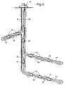
- Figure 4 shows a typical arrangement of a well bore with a number of branches.
- the borehole is lined with a casing comprising a steel pipe 28, cemented into position within the main bore.
- Production tubing 29 extends from the mouth 30 of the bore to oil reservoirs.
- the space, or annulus, between the casing 28 and the tubing 29 is sealed at points along the length of the tubing by means of devices known as packers 25.
- chokes 26 Interposed between adjacent packers 25 are chokes 26 which are each operated by actuators, such as that illustrated in Figure 1 or 2.
- oil enters the production tubing 29 either through the open lower ends at the ends of the branches, or through the slots in the choke devices 26, if open.
- the selection and operation of the motors associated with the choke actuators is carried out by operator selection by means of a surface control display. Sensors (not shown) may be employed to provide the operator with accurate information regarding the position and condition of the chokes 26.
- the invention permits fine control of the chokes, 26, or other loads, to achieve balancing of the pressures and/or flows in the system. Furthermore, the invention is reliable owing to the independent power source backups. Additionally, the invention provides additional operating forces if required in an emergency.
- one of the motors is hydraulic, the other electric, although both motors may be hydraulically or electrically driven.
- both motors may be hydraulically or electrically driven.
- other types of motors may be employed.
- bidirectional motors produce different output powers, in dependence on the direction of rotation.
- the single bidirectional motor 2 or 16 may be replaced by two back to back unidirectional motors.
- the bidirectional motor 2 (or 16), illustrated in Figures 1 and 2 may be replaced by two bidirectional motors, mounted at different angles with respect to each other. This arrangement reduces the effect of ripple of the motor torques, which is a typical characteristic of the positive displacement type of motors.
- Such motors also typically have a sinusoidal variation of output torque with rotational angle, so that, at some angular positions of the motor shaft, there will be a reduced torque output. Mounting the motors back to back so that the sinusoidal ripples of output torque are 180° out of phase with each other results in a major reduction of torque minimums and thus optimises the output torque of the motor pair, particularly at startup. This gives the actuator the best opportunity to overcome friction, at startup, of the device it is actuating for example a downhole choke sleeve.
- Both the bidirectional or unidirectional motors can be supplied from separate power sources to further increase the reliability of the system employing the actuator.
- Both of the motors may be hydraulic, or alternatively both electric, so that a backup drive facility is provided from two independent hydraulic or electric power sources.
- More than one output rod 3 may be provided.
- An internally threaded carriage may be substituted for either, or both, of the carriage and nut arrangements 6, 7 and 14, 15. Alternatively, either, or both, of the carriages may be arranged to run on rollers engaged by the external thread of the respective shaft.
- the internally threaded members 5, 13 may in fact be replaced by any arrangement for producing linear motion by cooperation with a rotating, externally threaded shaft.
- the invention may also be applied to any other downhole tools and production devices regarding a push/pull operation, in a well bore environment.
- the invention may also find application in the control of aircraft.
Landscapes
- Engineering & Computer Science (AREA)
- General Engineering & Computer Science (AREA)
- Geology (AREA)
- Life Sciences & Earth Sciences (AREA)
- Mining & Mineral Resources (AREA)
- Geochemistry & Mineralogy (AREA)
- Fluid Mechanics (AREA)
- General Life Sciences & Earth Sciences (AREA)
- Environmental & Geological Engineering (AREA)
- Physics & Mathematics (AREA)
- Mechanical Engineering (AREA)
- Transmission Devices (AREA)
- Valve Device For Special Equipments (AREA)
- Fluid-Driven Valves (AREA)
- Actuator (AREA)
Description
Claims (19)
- An actuator (1) for moving a load, the actuator comprising an output region (3) arranged to engage the load and first and second rotary motor means (2, 16) for imparting linear motion to said output region (3), the first and second rotary motor means (2,16) producing rotation about an axis parallel to the direction of linear motion, the first and second rotary motor means (2,16) being independently operable to effect movement of the output region (3);
characterised by the actuator (1) being arranged so that, in a first mode of operation, the first rotary motor means (2) imparts linear motion to the output region (3) via a first screw connection (4, 5); and, in a second mode of operation, the second rotary motor means (16) imparts linear motion to the output region (3) via a second screw connection (12, 13). - An actuator as claimed in claim 1 arranged for controlling a choke, the output region arranged to engage a sleeve (22) of the choke.
- An actuator as claimed in claim 1 or 2, arranged so that, in the first mode of operation, the first screw connection (4, 5) bears upon an intermediary member (11) in connection with the second screw connection (12, 13), thereby to impart linear motion to the output region (3).
- An actuator as claimed in any one of claims 1 to 3, arranged so that, in a third mode of operation, both first and second rotary motor means (2,16) are arranged to impart linear motion to the output region (3) via their respective screw connections (4, 5, 12, 13).
- An actuator as claimed in any preceding claim, wherein the first and second screw connections (4, 5, 12, 13) are aligned axially.
- An actuator as claimed in any preceding claim, wherein one of the first and second motor means (2, 16) hydraulic, the other of the first and second motor means being electric.
- An actuator as claimed in any one of claims 1 to 5, wherein the first and second motor means (2, 16) are both hydraulic.
- An actuator as claimed in any one of claims 1 to 5, wherein the first and second motor means (2, 16) are both electric.
- An actuator as claimed in any preceding claim, in which the first motor means (2) comprises two rotary motors, one of which is arranged to impart linear motion of the output region (3) in a first direction, the other of which is arranged to impart linear motion to the output region (3) in a second direction.
- An actuator as claimed in any one of claims 1 to 8, in which at least one of the first and second motor means (2, 16) comprises two rotary motors, one of which is arranged to impart linear motion of the output region (3) in a first direction, the other of which is arranged to impart linear motion of the output region (3) in a second direction.
- An actuator as claimed in claim 9 or 10, in which the motors of the respective motor means (2, 16) are aligned axially.
- An actuator as claimed in claim 9 or 10, in which at least one of the motors of the respective motor means (2,16) is offset from the axis of linear motion.
- An actuator as claimed in any preceding claim, in which at least one of the screw connections (4, 5, 12, 13) includes a carriage (7).
- An actuator as claimed in any one of claims 1 to 12, in which at least one of the screw connections (4, 5, 12, 13) includes a nut (6) carrying a carriage (7).
- An actuator as claimed in claim 13 or 14, further comprising guides for the carriage (7).
- An actuator as claimed in any preceding claim, in which at least one of the screw connections (4, 5, 12, 13) includes a splined shaft (18).
- An actuator as claimed in any preceding claim, in which the output region (3) is arranged, in use, to resist motion of the load or choke by an external force.
- A method of operating an actuator (1) to move a load comprising imparting linear motion to an output region (3) of the actuator by first and second rotary motor means (2, 16), said first and second rotary motor means (2, 16) producing rotary motion about an axis parallel to the direction of linear motion, and said first and second rotary motor means (2, 16) being independently operable to impart motion to the output region (3), the output region (3) being arranged to engage with the load;
characterised in that linear motion is imparted to the output region (3) by rotation of a first screw connection (4, 5) or a second screw connection (12, 13) effected by respective first and second rotary motor means (2, 16). - A method of operating an actuator as claimed in claim 19 to control a choke, the output region being arranged to engage with a sleeve (22) of the choke.
Applications Claiming Priority (3)
| Application Number | Priority Date | Filing Date | Title |
|---|---|---|---|
| GBGB9913037.9A GB9913037D0 (en) | 1999-06-05 | 1999-06-05 | Actuator |
| GB9913037 | 1999-06-05 | ||
| PCT/GB2000/002148 WO2000075483A1 (en) | 1999-06-05 | 2000-06-05 | Actuator |
Publications (2)
| Publication Number | Publication Date |
|---|---|
| EP1187967A1 EP1187967A1 (en) | 2002-03-20 |
| EP1187967B1 true EP1187967B1 (en) | 2004-08-25 |
Family
ID=10854758
Family Applications (1)
| Application Number | Title | Priority Date | Filing Date |
|---|---|---|---|
| EP00935393A Expired - Lifetime EP1187967B1 (en) | 1999-06-05 | 2000-06-05 | Actuator |
Country Status (8)
| Country | Link |
|---|---|
| US (1) | US6691587B1 (en) |
| EP (1) | EP1187967B1 (en) |
| AU (1) | AU5093700A (en) |
| BR (1) | BR0011056A (en) |
| DE (1) | DE60013281T2 (en) |
| GB (2) | GB9913037D0 (en) |
| NO (1) | NO320242B1 (en) |
| WO (1) | WO2000075483A1 (en) |
Families Citing this family (13)
| Publication number | Priority date | Publication date | Assignee | Title |
|---|---|---|---|---|
| GB2387977B (en) | 2002-04-17 | 2005-04-13 | Abb Offshore Systems Ltd | Control of hydrocarbon wells |
| GB2408987B (en) * | 2003-12-09 | 2006-11-15 | Abb Offshore Systems Ltd | Controlling a fluid well |
| US7237472B2 (en) * | 2004-01-09 | 2007-07-03 | Master Flo Valve, Inc. | Linear hydraulic stepping actuator with fast close capabilities |
| US6860464B1 (en) * | 2004-01-29 | 2005-03-01 | Honeywell International Inc. | Electromechanical/pneumatic rocket engine valve actuator |
| US7617873B2 (en) | 2004-05-28 | 2009-11-17 | Schlumberger Technology Corporation | System and methods using fiber optics in coiled tubing |
| US7467665B2 (en) * | 2005-11-08 | 2008-12-23 | Baker Hughes Incorporated | Autonomous circulation, fill-up, and equalization valve |
| US9133673B2 (en) * | 2007-01-02 | 2015-09-15 | Schlumberger Technology Corporation | Hydraulically driven tandem tractor assembly |
| GB2524035A (en) | 2014-03-12 | 2015-09-16 | Neptune Subsea Engineering Ltd | A powered subsea tool assembly, to reinstate the intended functionality of a subsea tree valve actuator |
| US9816592B1 (en) * | 2014-10-03 | 2017-11-14 | Tol-O-Matic, Inc. | Actuator for choke valve |
| US10536052B2 (en) | 2015-06-16 | 2020-01-14 | Tolomatic, Inc. | Actuator for choke valve |
| GB201516031D0 (en) | 2015-09-10 | 2015-10-28 | Neptune Subsea Engineering Ltd | Apparatus & method |
| DK3810889T3 (en) | 2018-06-22 | 2024-10-21 | Schlumberger Technology Bv | Full bore electric flow control valve system |
| US12546184B2 (en) | 2024-05-30 | 2026-02-10 | Schlumberger Technology Corporation | Choke system to control fluid pressure |
Family Cites Families (21)
| Publication number | Priority date | Publication date | Assignee | Title |
|---|---|---|---|---|
| JPS54142483A (en) | 1978-04-27 | 1979-11-06 | Fuji Photo Film Co Ltd | X y transfering mechanism |
| US4292842A (en) * | 1979-05-25 | 1981-10-06 | Gearhart Industries, Inc. | Tool for testing earth formations in boreholes |
| US4270385A (en) * | 1979-05-25 | 1981-06-02 | Gearhart Owen Industries, Inc. | Tool for testing earth formations in boreholes |
| US4246782A (en) * | 1980-05-05 | 1981-01-27 | Gearhart-Owen Industries, Inc. | Tool for testing earth formations in boreholes |
| GB2092702B (en) | 1981-02-07 | 1984-07-18 | Tully Engineering Co Ltd | Improvements in or relating to screw and nut actuators |
| DE3270901D1 (en) | 1981-12-18 | 1986-06-05 | Lars Int Sa | Linear drive device with two motors |
| GB2159599B (en) | 1984-03-22 | 1987-02-18 | Smiths Industries Plc | Actuators |
| CH665894A5 (en) | 1984-08-24 | 1988-06-15 | Lars Int Sa | LINEAR DRIVE DEVICE. |
| JPS628459U (en) | 1985-07-02 | 1987-01-19 | ||
| US4637272A (en) | 1985-10-28 | 1987-01-20 | Sundstrand Corporation | Ballscrew actuator |
| GB8612061D0 (en) | 1986-05-17 | 1986-06-25 | Westinghouse Brake & Signal | Electric actuators |
| DE8703448U1 (en) | 1987-03-07 | 1987-04-30 | Licentia Patent-Verwaltungs-GmbH, 60325 Frankfurt | Device for spatially adjusting an object |
| US5115415A (en) * | 1991-03-06 | 1992-05-19 | Baker Hughes Incorporated | Stepper motor driven negative pressure pulse generator |
| DK171715B1 (en) | 1994-05-31 | 1997-04-01 | Linak As | Linear actuator |
| US5673593A (en) * | 1995-12-14 | 1997-10-07 | Joerns Healthcare, Inc. | Overrunning nut for linear actuator |
| CA2218259C (en) * | 1996-02-15 | 2005-01-11 | Baker Hughes Incorporated | Motor drive actuator for downhole flow control devices |
| CA2201661A1 (en) * | 1996-04-04 | 1997-10-04 | Baker Hughes Incorporated | Valve actuator |
| US5704250A (en) * | 1996-04-04 | 1998-01-06 | Western Atlas, Inc. | Ball screw drive with dynamically adjustable preload |
| JP2002066763A (en) * | 2000-09-01 | 2002-03-05 | Honda Motor Co Ltd | Friction stir welding equipment |
| GB0107851D0 (en) * | 2001-03-29 | 2001-05-23 | Lucas Industries Ltd | Monitoring apparatus |
| US6585227B2 (en) * | 2001-07-26 | 2003-07-01 | Cooper Cameron Corporation | Roller screw actuator for subsea choke or module |
-
1999
- 1999-06-05 GB GBGB9913037.9A patent/GB9913037D0/en not_active Ceased
-
2000
- 2000-06-05 EP EP00935393A patent/EP1187967B1/en not_active Expired - Lifetime
- 2000-06-05 WO PCT/GB2000/002148 patent/WO2000075483A1/en not_active Ceased
- 2000-06-05 DE DE60013281T patent/DE60013281T2/en not_active Expired - Lifetime
- 2000-06-05 BR BR0011056-6A patent/BR0011056A/en not_active IP Right Cessation
- 2000-06-05 GB GB0013625A patent/GB2350659B/en not_active Expired - Fee Related
- 2000-06-05 AU AU50937/00A patent/AU5093700A/en not_active Abandoned
- 2000-06-05 US US09/980,465 patent/US6691587B1/en not_active Expired - Lifetime
-
2001
- 2001-12-04 NO NO20015929A patent/NO320242B1/en not_active IP Right Cessation
Also Published As
| Publication number | Publication date |
|---|---|
| NO320242B1 (en) | 2005-11-14 |
| NO20015929D0 (en) | 2001-12-04 |
| AU5093700A (en) | 2000-12-28 |
| GB9913037D0 (en) | 1999-08-04 |
| DE60013281D1 (en) | 2004-09-30 |
| EP1187967A1 (en) | 2002-03-20 |
| DE60013281T2 (en) | 2005-07-14 |
| WO2000075483A1 (en) | 2000-12-14 |
| GB2350659A (en) | 2000-12-06 |
| GB0013625D0 (en) | 2000-07-26 |
| GB2350659B (en) | 2003-07-30 |
| BR0011056A (en) | 2002-03-05 |
| US6691587B1 (en) | 2004-02-17 |
| NO20015929L (en) | 2002-02-01 |
Similar Documents
| Publication | Publication Date | Title |
|---|---|---|
| US6691587B1 (en) | Actuator | |
| US6041857A (en) | Motor drive actuator for downhole flow control devices | |
| EP1333207B1 (en) | Linear actuators | |
| AU2013217819B2 (en) | Device in a subsea electromechanical actuator and method for use of a subsea electromechanical actuator | |
| AU728634B2 (en) | Downhole flow control devices | |
| AU744372B2 (en) | Actuator apparatus and method for downhole completion tools | |
| US11333263B2 (en) | Electromechanical force actuator | |
| US10536052B2 (en) | Actuator for choke valve | |
| AU2022474549B2 (en) | Mechanical clutch for downhole tools | |
| US11898405B2 (en) | Mechanical disconnect for rotation drive | |
| US9816592B1 (en) | Actuator for choke valve | |
| AU729246B2 (en) | Motor drive actuator for downhole flow control devices | |
| CA3115992A1 (en) | Space-constrained hybrid linear actuator | |
| GB2216625A (en) | Mechanical actuator mechanism |
Legal Events
| Date | Code | Title | Description |
|---|---|---|---|
| PUAI | Public reference made under article 153(3) epc to a published international application that has entered the european phase |
Free format text: ORIGINAL CODE: 0009012 |
|
| 17P | Request for examination filed |
Effective date: 20020102 |
|
| AK | Designated contracting states |
Kind code of ref document: A1 Designated state(s): AT BE CH CY DE DK ES FI FR GB GR IE IT LI LU MC NL PT |
|
| AX | Request for extension of the european patent |
Free format text: AL;LT;LV;MK;RO;SI |
|
| 17Q | First examination report despatched |
Effective date: 20030811 |
|
| GRAP | Despatch of communication of intention to grant a patent |
Free format text: ORIGINAL CODE: EPIDOSNIGR1 |
|
| GRAS | Grant fee paid |
Free format text: ORIGINAL CODE: EPIDOSNIGR3 |
|
| GRAA | (expected) grant |
Free format text: ORIGINAL CODE: 0009210 |
|
| AK | Designated contracting states |
Kind code of ref document: B1 Designated state(s): DE FR |
|
| REG | Reference to a national code |
Ref country code: IE Ref legal event code: FG4D |
|
| REF | Corresponds to: |
Ref document number: 60013281 Country of ref document: DE Date of ref document: 20040930 Kind code of ref document: P |
|
| LTIE | Lt: invalidation of european patent or patent extension |
Effective date: 20040825 |
|
| REG | Reference to a national code |
Ref country code: FR Ref legal event code: CD |
|
| ET | Fr: translation filed | ||
| PLBE | No opposition filed within time limit |
Free format text: ORIGINAL CODE: 0009261 |
|
| 26N | No opposition filed |
Effective date: 20050526 |
|
| REG | Reference to a national code |
Ref country code: DE Ref legal event code: R082 Ref document number: 60013281 Country of ref document: DE Representative=s name: RUEGER, BARTHELT & ABEL PATENTANWAELTE, DE |
|
| REG | Reference to a national code |
Ref country code: DE Ref legal event code: R082 Ref document number: 60013281 Country of ref document: DE Representative=s name: RUEGER, BARTHELT & ABEL PATENTANWAELTE, DE Ref country code: DE Ref legal event code: R081 Ref document number: 60013281 Country of ref document: DE Owner name: GE OIL & GAS UK LTD., GB Free format text: FORMER OWNER: VETCO GRAY CONTROLS LTD., NAILSEA, BRISTOL, GB |
|
| REG | Reference to a national code |
Ref country code: FR Ref legal event code: PLFP Year of fee payment: 16 |
|
| PGFP | Annual fee paid to national office [announced via postgrant information from national office to epo] |
Ref country code: DE Payment date: 20150629 Year of fee payment: 16 |
|
| PGFP | Annual fee paid to national office [announced via postgrant information from national office to epo] |
Ref country code: FR Payment date: 20150617 Year of fee payment: 16 |
|
| REG | Reference to a national code |
Ref country code: FR Ref legal event code: TP Owner name: GE OIL & GAS UK LIMITED, GB Effective date: 20151116 |
|
| REG | Reference to a national code |
Ref country code: DE Ref legal event code: R119 Ref document number: 60013281 Country of ref document: DE |
|
| REG | Reference to a national code |
Ref country code: FR Ref legal event code: ST Effective date: 20170228 |
|
| PG25 | Lapsed in a contracting state [announced via postgrant information from national office to epo] |
Ref country code: DE Free format text: LAPSE BECAUSE OF NON-PAYMENT OF DUE FEES Effective date: 20170103 Ref country code: FR Free format text: LAPSE BECAUSE OF NON-PAYMENT OF DUE FEES Effective date: 20160630 |