EP1187668B1 - Chemical reactor with pressure swing adsorption - Google Patents
Chemical reactor with pressure swing adsorption Download PDFInfo
- Publication number
- EP1187668B1 EP1187668B1 EP00938400A EP00938400A EP1187668B1 EP 1187668 B1 EP1187668 B1 EP 1187668B1 EP 00938400 A EP00938400 A EP 00938400A EP 00938400 A EP00938400 A EP 00938400A EP 1187668 B1 EP1187668 B1 EP 1187668B1
- Authority
- EP
- European Patent Office
- Prior art keywords
- component
- pressure
- gas
- flow paths
- reactant
- Prior art date
- Legal status (The legal status is an assumption and is not a legal conclusion. Google has not performed a legal analysis and makes no representation as to the accuracy of the status listed.)
- Expired - Lifetime
Links
- 238000001179 sorption measurement Methods 0.000 title claims abstract description 19
- 239000000126 substance Substances 0.000 title description 2
- 238000006243 chemical reaction Methods 0.000 claims abstract description 85
- 239000000376 reactant Substances 0.000 claims abstract description 42
- 239000003054 catalyst Substances 0.000 claims abstract description 29
- 238000000926 separation method Methods 0.000 claims abstract description 14
- 239000007789 gas Substances 0.000 claims description 116
- 238000010992 reflux Methods 0.000 claims description 80
- 238000000034 method Methods 0.000 claims description 56
- 230000008569 process Effects 0.000 claims description 55
- CURLTUGMZLYLDI-UHFFFAOYSA-N Carbon dioxide Chemical group O=C=O CURLTUGMZLYLDI-UHFFFAOYSA-N 0.000 claims description 44
- 239000003463 adsorbent Substances 0.000 claims description 44
- 229910052739 hydrogen Inorganic materials 0.000 claims description 29
- 239000001257 hydrogen Substances 0.000 claims description 29
- 239000000463 material Substances 0.000 claims description 29
- QGZKDVFQNNGYKY-UHFFFAOYSA-N Ammonia Chemical group N QGZKDVFQNNGYKY-UHFFFAOYSA-N 0.000 claims description 28
- VNWKTOKETHGBQD-UHFFFAOYSA-N methane Chemical group C VNWKTOKETHGBQD-UHFFFAOYSA-N 0.000 claims description 26
- 238000007789 sealing Methods 0.000 claims description 25
- 239000001569 carbon dioxide Substances 0.000 claims description 22
- 229910002092 carbon dioxide Inorganic materials 0.000 claims description 22
- 230000006835 compression Effects 0.000 claims description 21
- 238000007906 compression Methods 0.000 claims description 21
- 239000000203 mixture Substances 0.000 claims description 20
- 239000012530 fluid Substances 0.000 claims description 19
- UFHFLCQGNIYNRP-UHFFFAOYSA-N Hydrogen Chemical compound [H][H] UFHFLCQGNIYNRP-UHFFFAOYSA-N 0.000 claims description 18
- 125000006850 spacer group Chemical group 0.000 claims description 17
- 239000011888 foil Substances 0.000 claims description 16
- 229910052751 metal Inorganic materials 0.000 claims description 16
- 239000002184 metal Substances 0.000 claims description 16
- 238000010926 purge Methods 0.000 claims description 15
- 229910021529 ammonia Inorganic materials 0.000 claims description 14
- OKKJLVBELUTLKV-UHFFFAOYSA-N Methanol Chemical group OC OKKJLVBELUTLKV-UHFFFAOYSA-N 0.000 claims description 12
- IJGRMHOSHXDMSA-UHFFFAOYSA-N nitrogen Substances N#N IJGRMHOSHXDMSA-UHFFFAOYSA-N 0.000 claims description 12
- UGFAIRIUMAVXCW-UHFFFAOYSA-N Carbon monoxide Chemical group [O+]#[C-] UGFAIRIUMAVXCW-UHFFFAOYSA-N 0.000 claims description 9
- 150000002431 hydrogen Chemical group 0.000 claims description 9
- 238000012546 transfer Methods 0.000 claims description 9
- 230000002787 reinforcement Effects 0.000 claims description 8
- 229910002091 carbon monoxide Inorganic materials 0.000 claims description 7
- 229910052757 nitrogen Inorganic materials 0.000 claims description 7
- 230000002829 reductive effect Effects 0.000 claims description 7
- QVGXLLKOCUKJST-UHFFFAOYSA-N atomic oxygen Chemical group [O] QVGXLLKOCUKJST-UHFFFAOYSA-N 0.000 claims description 5
- 239000011230 binding agent Substances 0.000 claims description 5
- 238000004891 communication Methods 0.000 claims description 5
- 239000003365 glass fiber Substances 0.000 claims description 5
- 239000001301 oxygen Substances 0.000 claims description 5
- 229910052760 oxygen Inorganic materials 0.000 claims description 5
- 239000011343 solid material Substances 0.000 claims description 5
- 239000010457 zeolite Substances 0.000 claims description 5
- PXHVJJICTQNCMI-UHFFFAOYSA-N Nickel Chemical compound [Ni] PXHVJJICTQNCMI-UHFFFAOYSA-N 0.000 claims description 4
- 229910021536 Zeolite Inorganic materials 0.000 claims description 4
- 125000004122 cyclic group Chemical group 0.000 claims description 4
- HNPSIPDUKPIQMN-UHFFFAOYSA-N dioxosilane;oxo(oxoalumanyloxy)alumane Chemical compound O=[Si]=O.O=[Al]O[Al]=O HNPSIPDUKPIQMN-UHFFFAOYSA-N 0.000 claims description 4
- 229930195733 hydrocarbon Natural products 0.000 claims description 4
- 150000002430 hydrocarbons Chemical group 0.000 claims description 4
- 239000011159 matrix material Substances 0.000 claims description 4
- 238000007084 catalytic combustion reaction Methods 0.000 claims description 3
- 239000002557 mineral fiber Substances 0.000 claims description 3
- 229910052782 aluminium Inorganic materials 0.000 claims description 2
- XAGFODPZIPBFFR-UHFFFAOYSA-N aluminium Chemical compound [Al] XAGFODPZIPBFFR-UHFFFAOYSA-N 0.000 claims description 2
- 238000009792 diffusion process Methods 0.000 claims description 2
- 125000004435 hydrogen atom Chemical group [H]* 0.000 claims description 2
- 229910052500 inorganic mineral Inorganic materials 0.000 claims description 2
- 239000007788 liquid Substances 0.000 claims description 2
- BASFCYQUMIYNBI-UHFFFAOYSA-N platinum Chemical group [Pt] BASFCYQUMIYNBI-UHFFFAOYSA-N 0.000 claims description 2
- XLYOFNOQVPJJNP-UHFFFAOYSA-N water Substances O XLYOFNOQVPJJNP-UHFFFAOYSA-N 0.000 claims description 2
- 239000004215 Carbon black (E152) Substances 0.000 claims 3
- 239000013529 heat transfer fluid Substances 0.000 claims 2
- 239000002638 heterogeneous catalyst Substances 0.000 claims 2
- QJGQUHMNIGDVPM-UHFFFAOYSA-N nitrogen group Chemical group [N] QJGQUHMNIGDVPM-UHFFFAOYSA-N 0.000 claims 2
- VGGSQFUCUMXWEO-UHFFFAOYSA-N Ethene Chemical compound C=C VGGSQFUCUMXWEO-UHFFFAOYSA-N 0.000 claims 1
- 239000005977 Ethylene Substances 0.000 claims 1
- 230000007423 decrease Effects 0.000 claims 1
- 230000003247 decreasing effect Effects 0.000 claims 1
- -1 methane Chemical class 0.000 claims 1
- 230000000712 assembly Effects 0.000 abstract 1
- 238000000429 assembly Methods 0.000 abstract 1
- 239000000047 product Substances 0.000 description 37
- 239000002594 sorbent Substances 0.000 description 13
- 238000004519 manufacturing process Methods 0.000 description 10
- 239000006096 absorbing agent Substances 0.000 description 9
- 230000015572 biosynthetic process Effects 0.000 description 6
- 238000003786 synthesis reaction Methods 0.000 description 6
- 238000011084 recovery Methods 0.000 description 5
- 238000010438 heat treatment Methods 0.000 description 4
- 239000003345 natural gas Substances 0.000 description 4
- 230000010349 pulsation Effects 0.000 description 4
- 238000001991 steam methane reforming Methods 0.000 description 4
- 238000000629 steam reforming Methods 0.000 description 4
- XEEYBQQBJWHFJM-UHFFFAOYSA-N Iron Chemical compound [Fe] XEEYBQQBJWHFJM-UHFFFAOYSA-N 0.000 description 3
- VYPSYNLAJGMNEJ-UHFFFAOYSA-N Silicium dioxide Chemical compound O=[Si]=O VYPSYNLAJGMNEJ-UHFFFAOYSA-N 0.000 description 3
- 239000000446 fuel Substances 0.000 description 3
- 239000012071 phase Substances 0.000 description 3
- 230000002441 reversible effect Effects 0.000 description 3
- 230000003068 static effect Effects 0.000 description 3
- BVKZGUZCCUSVTD-UHFFFAOYSA-L Carbonate Chemical compound [O-]C([O-])=O BVKZGUZCCUSVTD-UHFFFAOYSA-L 0.000 description 2
- PNEYBMLMFCGWSK-UHFFFAOYSA-N aluminium oxide Inorganic materials [O-2].[O-2].[O-2].[Al+3].[Al+3] PNEYBMLMFCGWSK-UHFFFAOYSA-N 0.000 description 2
- 230000008859 change Effects 0.000 description 2
- 238000002485 combustion reaction Methods 0.000 description 2
- 238000009833 condensation Methods 0.000 description 2
- 230000005494 condensation Effects 0.000 description 2
- 239000013078 crystal Substances 0.000 description 2
- 238000003795 desorption Methods 0.000 description 2
- GDVKFRBCXAPAQJ-UHFFFAOYSA-A dialuminum;hexamagnesium;carbonate;hexadecahydroxide Chemical compound [OH-].[OH-].[OH-].[OH-].[OH-].[OH-].[OH-].[OH-].[OH-].[OH-].[OH-].[OH-].[OH-].[OH-].[OH-].[OH-].[Mg+2].[Mg+2].[Mg+2].[Mg+2].[Mg+2].[Mg+2].[Al+3].[Al+3].[O-]C([O-])=O GDVKFRBCXAPAQJ-UHFFFAOYSA-A 0.000 description 2
- 238000010494 dissociation reaction Methods 0.000 description 2
- 230000005593 dissociations Effects 0.000 description 2
- 238000009826 distribution Methods 0.000 description 2
- 239000004744 fabric Substances 0.000 description 2
- 239000011152 fibreglass Substances 0.000 description 2
- 229910001701 hydrotalcite Inorganic materials 0.000 description 2
- 229960001545 hydrotalcite Drugs 0.000 description 2
- 230000002427 irreversible effect Effects 0.000 description 2
- 238000007726 management method Methods 0.000 description 2
- 230000036961 partial effect Effects 0.000 description 2
- 238000005192 partition Methods 0.000 description 2
- 238000005086 pumping Methods 0.000 description 2
- 238000000746 purification Methods 0.000 description 2
- 239000007790 solid phase Substances 0.000 description 2
- 238000012935 Averaging Methods 0.000 description 1
- 235000008733 Citrus aurantifolia Nutrition 0.000 description 1
- 235000011941 Tilia x europaea Nutrition 0.000 description 1
- 238000010521 absorption reaction Methods 0.000 description 1
- 238000013459 approach Methods 0.000 description 1
- 238000003491 array Methods 0.000 description 1
- 238000002453 autothermal reforming Methods 0.000 description 1
- 238000011021 bench scale process Methods 0.000 description 1
- 239000006227 byproduct Substances 0.000 description 1
- 229910002090 carbon oxide Inorganic materials 0.000 description 1
- 230000003197 catalytic effect Effects 0.000 description 1
- 238000001193 catalytic steam reforming Methods 0.000 description 1
- 238000001311 chemical methods and process Methods 0.000 description 1
- 239000007795 chemical reaction product Substances 0.000 description 1
- 239000004927 clay Substances 0.000 description 1
- 239000011248 coating agent Substances 0.000 description 1
- 238000000576 coating method Methods 0.000 description 1
- 239000012141 concentrate Substances 0.000 description 1
- 239000000470 constituent Substances 0.000 description 1
- 230000001351 cycling effect Effects 0.000 description 1
- 238000006356 dehydrogenation reaction Methods 0.000 description 1
- 239000006185 dispersion Substances 0.000 description 1
- 238000004821 distillation Methods 0.000 description 1
- 238000004049 embossing Methods 0.000 description 1
- 238000005530 etching Methods 0.000 description 1
- 239000003546 flue gas Substances 0.000 description 1
- 238000005338 heat storage Methods 0.000 description 1
- 239000010763 heavy fuel oil Substances 0.000 description 1
- 238000005984 hydrogenation reaction Methods 0.000 description 1
- 229910052742 iron Inorganic materials 0.000 description 1
- 239000004571 lime Substances 0.000 description 1
- 239000012263 liquid product Substances 0.000 description 1
- 229910001338 liquidmetal Inorganic materials 0.000 description 1
- 239000012528 membrane Substances 0.000 description 1
- 229910003455 mixed metal oxide Inorganic materials 0.000 description 1
- 238000012986 modification Methods 0.000 description 1
- 230000004048 modification Effects 0.000 description 1
- 229910052759 nickel Inorganic materials 0.000 description 1
- 239000004745 nonwoven fabric Substances 0.000 description 1
- 238000007254 oxidation reaction Methods 0.000 description 1
- 238000007639 printing Methods 0.000 description 1
- 239000012264 purified product Substances 0.000 description 1
- 238000005057 refrigeration Methods 0.000 description 1
- 230000001172 regenerating effect Effects 0.000 description 1
- 238000013341 scale-up Methods 0.000 description 1
- 239000000741 silica gel Substances 0.000 description 1
- 229910002027 silica gel Inorganic materials 0.000 description 1
- 239000000377 silicon dioxide Substances 0.000 description 1
- 239000002002 slurry Substances 0.000 description 1
- 239000007787 solid Substances 0.000 description 1
- 238000011064 split stream procedure Methods 0.000 description 1
- 230000004936 stimulating effect Effects 0.000 description 1
- 230000007704 transition Effects 0.000 description 1
- 239000006200 vaporizer Substances 0.000 description 1
- 238000013022 venting Methods 0.000 description 1
- 239000011800 void material Substances 0.000 description 1
- 239000002759 woven fabric Substances 0.000 description 1
Images




Classifications
-
- B—PERFORMING OPERATIONS; TRANSPORTING
- B01—PHYSICAL OR CHEMICAL PROCESSES OR APPARATUS IN GENERAL
- B01D—SEPARATION
- B01D53/00—Separation of gases or vapours; Recovering vapours of volatile solvents from gases; Chemical or biological purification of waste gases, e.g. engine exhaust gases, smoke, fumes, flue gases, aerosols
- B01D53/02—Separation of gases or vapours; Recovering vapours of volatile solvents from gases; Chemical or biological purification of waste gases, e.g. engine exhaust gases, smoke, fumes, flue gases, aerosols by adsorption, e.g. preparative gas chromatography
- B01D53/06—Separation of gases or vapours; Recovering vapours of volatile solvents from gases; Chemical or biological purification of waste gases, e.g. engine exhaust gases, smoke, fumes, flue gases, aerosols by adsorption, e.g. preparative gas chromatography with moving adsorbents, e.g. rotating beds
-
- B—PERFORMING OPERATIONS; TRANSPORTING
- B01—PHYSICAL OR CHEMICAL PROCESSES OR APPARATUS IN GENERAL
- B01D—SEPARATION
- B01D53/00—Separation of gases or vapours; Recovering vapours of volatile solvents from gases; Chemical or biological purification of waste gases, e.g. engine exhaust gases, smoke, fumes, flue gases, aerosols
- B01D53/02—Separation of gases or vapours; Recovering vapours of volatile solvents from gases; Chemical or biological purification of waste gases, e.g. engine exhaust gases, smoke, fumes, flue gases, aerosols by adsorption, e.g. preparative gas chromatography
- B01D53/04—Separation of gases or vapours; Recovering vapours of volatile solvents from gases; Chemical or biological purification of waste gases, e.g. engine exhaust gases, smoke, fumes, flue gases, aerosols by adsorption, e.g. preparative gas chromatography with stationary adsorbents
- B01D53/047—Pressure swing adsorption
-
- B—PERFORMING OPERATIONS; TRANSPORTING
- B01—PHYSICAL OR CHEMICAL PROCESSES OR APPARATUS IN GENERAL
- B01D—SEPARATION
- B01D2257/00—Components to be removed
- B01D2257/50—Carbon oxides
- B01D2257/504—Carbon dioxide
-
- B—PERFORMING OPERATIONS; TRANSPORTING
- B01—PHYSICAL OR CHEMICAL PROCESSES OR APPARATUS IN GENERAL
- B01D—SEPARATION
- B01D2259/00—Type of treatment
- B01D2259/40—Further details for adsorption processes and devices
- B01D2259/40003—Methods relating to valve switching
- B01D2259/40005—Methods relating to valve switching using rotary valves
-
- Y—GENERAL TAGGING OF NEW TECHNOLOGICAL DEVELOPMENTS; GENERAL TAGGING OF CROSS-SECTIONAL TECHNOLOGIES SPANNING OVER SEVERAL SECTIONS OF THE IPC; TECHNICAL SUBJECTS COVERED BY FORMER USPC CROSS-REFERENCE ART COLLECTIONS [XRACs] AND DIGESTS
- Y02—TECHNOLOGIES OR APPLICATIONS FOR MITIGATION OR ADAPTATION AGAINST CLIMATE CHANGE
- Y02C—CAPTURE, STORAGE, SEQUESTRATION OR DISPOSAL OF GREENHOUSE GASES [GHG]
- Y02C20/00—Capture or disposal of greenhouse gases
- Y02C20/40—Capture or disposal of greenhouse gases of CO2
-
- Y—GENERAL TAGGING OF NEW TECHNOLOGICAL DEVELOPMENTS; GENERAL TAGGING OF CROSS-SECTIONAL TECHNOLOGIES SPANNING OVER SEVERAL SECTIONS OF THE IPC; TECHNICAL SUBJECTS COVERED BY FORMER USPC CROSS-REFERENCE ART COLLECTIONS [XRACs] AND DIGESTS
- Y02—TECHNOLOGIES OR APPLICATIONS FOR MITIGATION OR ADAPTATION AGAINST CLIMATE CHANGE
- Y02P—CLIMATE CHANGE MITIGATION TECHNOLOGIES IN THE PRODUCTION OR PROCESSING OF GOODS
- Y02P20/00—Technologies relating to chemical industry
- Y02P20/50—Improvements relating to the production of bulk chemicals
- Y02P20/582—Recycling of unreacted starting or intermediate materials
Definitions
- the invention relates to chemical reactions conducted in the gas or vapour phase. Reactions may be exothermic or endothermic, and are conducted over a catalyst. Some particular applications include ammonia synthesis, methanol synthesis, conversion of natural gas or syngas to liquid fuels, hydrogenation and dehydrogenation reactions, and controlled oxidation reactions.
- PSA pressure swing adsorption
- a "heavy" product enriched in the more strongly adsorbed component is exhausted from the first end of the bed.
- the feed is admitted to the first end of a bed and the second product delivered from the second end of the. bed when the pressure in that bed is elevated to a higher working pressure, while the second product is exhausted from the first end of the bed at a lower working pressure which is the low pressure of the cycle.
- the conventional process for gas separation by pressure swing adsorption uses two or more adsorbent beds in parallel, with directional valving at each end of each adsorbent bed to connect the beds in alternating sequence to pressure sources and sinks, thus establishing the changes of working pressure and flow direction.
- This conventional pressure swing adsorption process makes inefficient use of applied energy, because of irreversible expansion over the valves over large pressure differences while switching the adsorbent beds between higher and lower pressures.
- the present invention integrates the chemical reactor with pressure swing adsorption as the product/reactant separation process.
- One aspect of the present invention provides a process for conducting a chemical reaction in accordance with the features of Claim 1.
- Another aspect of the present invention provides a rotary module having the features of Claim 31.
- the present invention conducts a chemical reaction in cooperation with a rotary module for pressure swing adsorption separation of the reaction product(s) from the reactant(s), with high energy efficiency and with compact machinery of low capital cost.
- the inventive apparatus includes a rotary module for PSA separation of a gas mixture containing a more readily adsorbed component and a less readily adsorbed component, with the more readily adsorbed component being preferentially adsorbed from the feed gas mixture by an adsorbent material under increase of pressure, so as to separate from the gas mixture a heavy product gas enriched in the more readily adsorbed component, and a light product gas enriched in the less readily adsorbed component and depleted in the more readily adsorbed component.
- the apparatus typically includes axial or centrifugal compression machinery cooperating with one or multiple PSA modules in parallel.
- Each PSA module comprises a plurality of adsorbers, with each adsorber having a flow path contacting adsorbent material between first and second ends of the flow path.
- Each PSA module further has a first valve means cooperating with the adsorbers to admit feed gas to the first ends of the adsorbers, and to exhaust heavy product gas from the first ends of the adsorbers.
- Each PSA module also has a second valve means cooperating with the adsorbers to deliver light product gas from the second ends of the adsorbers, to withdraw light reflux gas from the second ends of the adsorbers, and to return light reflux gas to the second ends of the adsorbers.
- the term "light reflux” refers to withdrawal of light gas (enriched in the less readily adsorbed component) from the second ends of adsorbers via the second valve means, followed by pressure let-down and return of that light gas to other adsorbers at a lower pressure via the second valve means.
- the first and second valve means are operated so as to define the steps of a PSA cycle performed sequentially in each of the adsorbers, while controlling the timings of flow at specified total pressure levels between the adsorbers and the compression machinery.
- the PSA process of the invention establishes the PSA cycle in each adsorber, within which the total working pressure in each adsorber is cycled between a higher pressure and a lower pressure of the PSA cycle.
- the PSA process also provides a plurality of intermediate pressures between the higher and lower pressure.
- the compression machinery of the apparatus in general include multistage axial or centrifugal compressors and expanders.
- the feed compressor will typically supply feed gas, in several stages at discrete intermediate pressures for feed pressurization of the adsorbers as well as the higher pressure for light product production, to the first valve means.
- the exhauster will typically receive second product gas, in several stages at discrete intermediate pressures for countercurrent blowdown of the adsorbers as well as the lower pressure, from the first valve means.
- the light reflux expander may also perform pressure let-down on several separate light reflux stages, sequentially drawn from the second valve means at a set of discrete intermediate pressure levels, and after expansion returned to the second valve means at a lower set of discrete intermediate pressure levels.
- Heat exchangers may be provided to heat gas streams about to be expanded, for thermally boosted energy recovery.
- each PSA module will preferably have a sufficiently large number of adsorbers for several adsorbers to be undergoing each step of the PSA cycle at any moment.
- the several adsorbers passing through the step would be in sequentially phased converging approach to the nominal pressure level of each step by a throttling pressure equalization from the pressure level of the previous step experienced by the adsorbers.
- Flow is being provided to the adsorbers in a pressurization step or withdrawn in a blowdown step by the compression machinery at the nominal pressure level of that step.
- flow and pressure pulsations seen by the compression machinery at each intermediate pressure level are minimal by averaging from the several adsorbers passing through the step, although each adsorber undergoes large cyclic changes of pressure and flow.
- a preferred way to provide a large number of adsorbers in a mechanically simple PSA module is to instal those adsorbers as angularly spaced elements in a rotor, whose opposed faces engaging across sealing faces with a ported stator sealing faces will provide the first and second valve means.
- surge absorber chambers will be needed to isolate each stage of the compression machinery from excessive pulsations of flow and pressure. With sufficiently large surge absorber chambers, flow and pressure pulsations seen by the compression machinery are again minimized.
- the principle of using compression and expansion machinery (with compression performed predominantly in communication with the first ends of the adsorbers, and expansion energy recovery performed on cocurrent blowdown from the second ends of the adsorbers) to generate a high performance PSA cycle is referred to as "Thermally Coupled Pressure Swing Adsorption" or TCPSA, because of the inherent heat pumping aspect resulting from a close mechanical analogy to Stirling or Ericsson cycle thermodynamic engines.
- the present invention provides multistage or split stream compression/expansion machinery for the multiple gas flows at multiple closely spaced intermediate pressure levels, enabled by the present PSA process.
- the multistage machinery may be provided as separate machines operating in series or parallel, or preferably as multiple impellers in tandem on a single shaft within a single casing.
- Heat exchangers may be optionally provided as compression intercoolers to reject heat of compression, and as heaters to heat either (or both) the countercurrent blowdown gas or the light reflux gas about to be expanded.
- the heater may be provided with heat from an external source, or may use heat of compression from the compression intercoolers as another mode of energy recovery within the apparatus and process of the invention. Heat may also be provided to or removed the adsorbers by providing heat exchange surfaces within the rotor.
- Fig. 1 shows an elementary PSA apparatus 1 with an adsorber assembly 2 having a plurality of "N" cooperating adsorbers 3 in parallel.
- Each adsorber 3 has a flow path 4 between first end 5 and second end 6 of the adsorber 3, with adsorbent material contacting the flow path.
- Cooperating with the adsorbers 3 are first valve means 7 and second valve means 8.
- Arrow 9 indicates the direction of progression of the adsorbers 3 in being connected to ports of the first and second valve means 7, 8 as shown in Fig. 1.
- adsorber rotor 2 is shown in Fig. 1 unrolled in a 360o section about its rotary axis so that rotation causes the adsorbers 3 to advance in the direction of arrow 9 to undergo the cycle of Fig. 2.
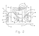
- FIG. 2 shows the PSA cycle undergone sequentially by each of the "N" adsorbers 3 over a cycle period "T".
- the cycle in consecutive adsorbers 3 is displaced in phase by a time interval of T/N.
- the vertical axis 10 indicates the working pressure in an adsorber element.
- the higher and lower working pressures of the PSA process are respectively indicated by dotted lines 11 and 12.
- the horizontal axis 15 indicates time, with the PSA cycle period defined by the time interval between points 16 and 17.
- the working pressure in the first adsorber 3 on the left in Figure 1 is pressure 18.
- the cycle begins as the first end 5 of adsorber 3 is opened by the first valve means 7 to first feed supply means 20 at the first intermediate feed pressure 21.
- the pressure in adsorber 3 rises from pressure 18 at time 17 to the first intermediate feed pressure 21.
- the first end 5 is opened next to second feed supply means 22 at the second intermediate feed pressure 23.
- the adsorber pressure rises to the second intermediate feed pressure.
- first end 5 is opened to a third feed supply means 24 at the higher pressure 11 of the PSA process.
- the adsorber pressure has risen to substantially the higher working pressure, its second end 6 is opened by the second valve means 8 to light product delivery conduit 25 to deliver purified light product.
- the second end 6 is next closed to light product delivery conduit 25, and is opened to deliver "light reflux" gas (enriched in the less readily adsorbed component, similar to second product gas) by conduit 29 to first light reflux pressure let-down means 30.
- the light reflux pressure let-down means 30 may be an expander with optional heat exchangers such as an inlet heater, or a throttle orifice.
- All or some of the feed supply means may be feed compression stages.
- the first end 5 of adsorber 3 is then closed by the first valve means 7, while the second end 6 is opened successively by the second valve means 8 to (a) drop the adsorber pressure to the first cocurrent blowdown pressure 32 while delivering light reflux gas by conduit 33 to second light reflux pressure letdown means 34, (b) drop the adsorber pressure to the second cocurrent blowdown pressure 36 while delivering light reflux gas by conduit 37 to third light reflux pressure letdown means 38, and (c) drop the adsorber pressure to the third cocurrent blowdown pressure 40 while delivering light reflux gas by conduit 41 to fourth light reflux pressure letdown means 42. Second end 6 is then closed for an interval, until the light reflux return steps following the countercurrent blowdown steps.
- the light reflux pressure let-down means 30, 34, 38, 42 may be mechanical expansion stages for expansion energy recovery, or may be restrictor orifices or throttle valves for irreversible pressure let-down. Either when the second end 6 is closed after the final light reflux exit step (as shown in Fig. 2), or earlier while light reflux exit steps are still underway, first end 5 is opened to first exhaust means 46, dropping the adsorber pressure to the first countercurrent blowdown intermediate pressure 48 while releasing "heavy" gas (enriched in the more strongly adsorbed component) to the first exhaust means 46. Next, first end 5 is opened to second exhaust means 50, dropping the adsorber pressure to the second countercurrent blowdown intermediate pressure 52 while releasing "heavy" gas.
- first end 5 is opened to third exhaust means 54, dropping the adsorber pressure to the lower pressure 12 of the PSA process while releasing "heavy" gas.
- the second end 6 is opened to receive fourth light reflux gas (as purge gas) from fourth light reflux pressure let-down means 42 by conduit 55 in order to displace more heavy gas into the third exhaust means 54.
- the heavy gas from the first, second and third exhaust 46, 50, 54 means may be delivered together as the heavy product 56.
- All or some of the exhaust means may be mechanical exhauster stages, alternatively either expansion stages if the pressure is to be reduced, or vacuum pumping stages if the pressure is to be increased to ambient pressure, or exhaust compression stages if the exhaust of second product is to be delivered at an elevated pressure.
- An exhaust means may also be provided by venting to an external sink, e.g. the ambient atmosphere.
- the adsorber 3 is then repressurized by light reflux gas after the first end 5 is closed.
- the second end 6 is opened (a) to receive light reflux gas by conduit 59 from the third light reflux pressure letdown means 38 to raise the adsorber pressure to the first light reflux pressurization pressure 60, (b) to receive light reflux gas by conduit 61 from the second light reflux pressure letdown means 34 to raise the adsorber pressure to the second light reflux pressurization pressure 62, and (c) to receive light reflux gas by conduit 63 from the first light reflux pressure letdown means 30 to raise the adsorber pressure to the third light reflux pressurization pressure.
- the process begins feed pressurization for the next cycle after time 17 as soon as the third light reflux pressurization step has been concluded.
- feed flow is delivered by a conduit 70 through an optional surge absorber chamber 71 to a feed compartment 72 opening to a feed port 73 in first valve means 7.
- Feed compartment 72 may be open to several adsorbers 3 simultaneously, and may have a restricted entrance 74 so as to provide a gradual throttling equalization of pressure as each adsorber 3 is opened to feed compartment 72.
- First feed pressurization compartment 72 is fed by conduit 70
- second feed pressurization compartment 75 is fed by conduit 76
- feed production supply compartment 77 is fed by conduit 78.
- each exhaust means e.g. 46
- the exhaust flow is delivered by a conduit 80 through an optional surge absorber chamber 81 from an exhaust compartment 82 opening to an exhaust port 83 in first valve means 7.
- Exhaust compartment 82 may be open to several adsorbers 3 simultaneously, and may have a restricted entrance 84 so as to provide a gradual throttling equalization of pressure as each adsorber 3 is opened to exhaust compartment 82.
- first countercurrent blowdown exhaust compartment 82 exhausts to conduit 80
- a second countercurrent blowdown exhaust compartment 61 exhausts to conduit 63
- a purge exhaust compartment 65 exhausts to conduit 67.
- the light product is delivered through an optional surge absorber chamber 86 from light product exit compartment 87 opening to a light product port 88 in second valve means 8.
- Light reflux exit compartment 92 may be open to several adsorbers simultaneously, and may have a restricted entrance 94 so as to provide a gradual throttling equalization of pressure as each adsorber 3 is opened to light reflux exit compartment 92.
- Light reflux exit compartment 97 may be open to several adsorbers 3 simultaneously, and may have a restricted entrance 99 so as to provide a gradual throttling equalization of pressure as each adsorber 3 is opened to light reflux entrance compartment 97.
- the rate of pressure change in each pressurization or blowdown step may thus be restricted by throttling in compartments of the first and second valve means 7, 8, or by throttling in the ports at first and second ends 5, 6, of the adsorbers 3, resulting in the typical pressure waveform depicted in Fig. 2.
- Excessively rapid rates of pressure change would subject the adsorber 3 to mechanical stress, while also causing flow transients which would tend to increase axial dispersion of the concentration wavefront in the adsorber 3.
- Pulsations of flow and pressure are minimized by having a plurality of adsorbers simultaneously transiting each step of the cycle, and/or by providing surge absorbers in the conduits connecting to the first and second valve means 7, 8.
- the cycle shown in Fig. 2 could be generalized by having more or fewer intermediate stages in each major step of feed pressurization, countercurrent blowdown exhaust, or light reflux.
- adsorber pressurization could be achieved entirely by feed pressurization (or by pressurization with a component of the feed), or by light reflux represssuization.
- the length of the steps may be changed readily by changing the angular width of the ports.
- relatively gradual pressurization and blowdown steps may be desirable to overcome kinetic constraints or mechanical stress limitations.
- the first end 5 and second end 6 of the adsorbers 3 will be maintained at temperatures T1 and T2 respectively.
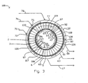
- Fig. 3 shows a sectional view of a rotary module 100 configured for radial flow.
- Rotor 2 contains the "N" adsorbers 3, with the flow path here oriented radially between first end 5 and second end 6 of the adsorbers 3.
- the adsorber first ends 5 open by apertures 106 to a sealing face 107 with the first valve stator 108, which has ports 109 to define the first valve means 7.
- First valve stator 108 has a plurality of functional compartments in fluid communication to sealing face 107 by ports 109, including a first feed pressurization supply compartment 72, a second first feed pressurization supply compartment 75, a feed production supply compartment 77 at substantially the higher pressure, a first countercurrent blowdown exhaust compartment 82, a second countercurrent blowdown exhaust compartment 61, and a purge exhaust compartment 65 at substantially the lower pressure.
- Second valve stator 105 includes, with each compartment in fluid communication to sealing face 119 by ports 120, a light product delivery compartment 87 at substantially the higher pressure, a first light reflux exit compartment which is here simply the downstream end of compartment 87 delivering gas to conduit 25.
- a second light reflux exit compartment 92 delivering gas to conduit 33, third and fourth light reflux exit compartments delivering gas to conduits 37 and 41 respectively, a fourth light reflux return compartment 97 receiving purge gas from conduit 55 at substantially the lower pressure, a third light reflux return compartment receiving gas from conduit 59, a second light reflux return compartment receiving gas from conduit 61, and a first light reflux return compartment receiving gas from conduit 63.
- the angular spacing of ports communicating to the compartments in the first and second valve stators 108, 105 defines the timing of the PSA cycle steps similar to the cycle of Fig. 2.
- sealing faces 107 and 119 are respectively defined by the outer and inner radii of the annular rotor 2. Fluid sealing between the functional compartments the in sealing faces 117 and 119 is achieved by clearance seals.
- the clearance seals are provided as slippers 130 attached to the first and second valve stators 108, 105 by partitions 131. Partitions 131 provide static sealing between adjacent compartments. Slippers 130 engage the sealing faces 107, 119 with narrow fluid sealing clearances, which also provide throttling of gas flows between the adsorbers 3 and functional compartments in each pressure-changing step, so that each adsorber may smoothly equalize in pressure to the pressure of the next functional compartment about to be opened to that adsorber 3.
- static pressure balancing compartments e.g. 132 and 133 are provided behind some clearance seal slippers 130.
- the static pressure balancing compartments are disposed in angular sectors of the first and second valve stators 108, 105 not used as functional compartments, in order to establish a controlled pressure distribution behind the clearance slippers 130 so as to maintain their positive sealing engagement without excessive contact pressure and consequent friction.
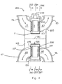
- Fig. 4 shows a sectional view of a rotary module 200 configured for axial flow
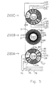
- Fig. 5 shows sectional views of the first valve face, the adsorbers 3, and the second valve face of the rotary module of Fig. 4.
- the flow path in adsorbers 3 is now parallel to axis 201.
- the steps of the process and functional compartments are still in the same angular relationship regardless of a radial or axial flow direction in the adsorbers 3.
- Sections 200A, 200B and 200C are cross sections of module 200 in the planes respectively defined by arrows 202 - 203, 204 - 205, and 206 - 207.
- the adsorber rotor 2 contains the "N" adsorbers 3 in adsorber wheel 208. and revolves within stator 103.
- circumferential seals 215 and 216 bound first sealing face 107, and circumferential seals 217 and 218 bound second sealing face 119.
- the sealing faces are flat discs.
- the circumferential seals also define the ends of clearance slippers 130 in the sealing faces between the functional compartments.
- Rotor 2 is supported by bearing 220 in housing 225, which is integrally assembled with the first and second valve stators.
- Rotor 2 is driven by rim drive motor 230, which may have a friction, geared or belt engagement with the outer rim of rotor 2.
- Section 200A shows the first valve face of embodiment 200 of Fig. 4, at section 202 - 203, with fluid connections to feed and to countercurrent blowdown.
- Arrow 270 indicates the direction of rotation by adsorber rotor 2.
- valve face 107 ported to the feed and exhaust compartments is indicated by clear angular segments 77, 82, 61, 65, 72, 75, and 77 corresponding to those functional compartments, between circumferential seals 215 and 216.
- the substantially closed area of valve face 107 between functional compartments is indicated by cross-hatched sectors 275 and 276 which are clearance slippers 130.
- Typical closed sector 275 provides a transition for an adsorber, between being open between two adjacent compartments. Gradual opening is provided by a tapering clearance channel between the slipper and the sealing face, so as to achieve gentle pressure equalization of an adsorber being opened to a new compartment.
- Much wider closed sectors e.g.
- Section 200 C is the second valve face of embodiment 200 of Fig. 4, at section 206 - 207. Similar principles and alternatives apply to radial flow and axial flow geometries, respectively sealing on cylindrical or disc faces.
- the adsorbers 3 are mounted between outer wall 280 and inner wall 281 of adsorber wheel 208.
- Each adsorber comprises a rectangular flat pack which is laminated of adsorbent sheets 282, with spacers between the sheets to define flow channels here in the axial direction. Separators 284 are provided between the adsorbers to fill void space and prevent leakage between the adsorbers 3.
- the adsorbent sheets 282 comprise a reinforcement material, in preferred embodiments glass fibre, metal foil or wire mesh. to which the adsorbent material is attached with a suitable binder.
- Typical adsorbents include zeolites, many of which are also active as catalysts for reactions of interest. The zeolite crystals are bound with silica, clay and other binders, or self-bound, within the adsorbent sheet matrix.
- Satisfactory adsorbent sheets have been made by coating a slurry of zeolite crystals with binder constituents onto the reinforcement material, with successful examples including nonwoven fiber glass scrims, woven metal fabrics, and expanded aluminum foils.
- Spacers are provided by printing or embossing the adsorbent sheet with a raised pattern, or by placing a fabricated spacer between adjacent pairs of adsorbent sheets.
- Alternative satisfactory spacers have been provided as woven metal screens, non-woven fiber glass scrims, and metal foils with etched flow channels in a photolithographic pattern.
- Typical experimental sheet thicknesses have been 150 microns, with spacer heights in the range of 100 microns, and adsorber flow channel length approximately 20 cm.
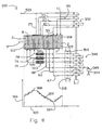
- An apparatus 300 for conducting an exothermic reaction in the example of ammonia synthesis, conducts the reaction within a zone 301 adjacent the second ends 6 of the adsorbers 3 in the rotary module.
- Zone 301 has catalyst active for stimulating the reaction in an extended portion of the adsorbers 3, with the catalyst preferably supported on sheets in a laminated parallel passage structure as described above for adsorbent sheets.
- the flow paths through the rotor include flow channels contacting adsorbent material, and the catalyst in zone 301 thereof.
- the lower part of Fig. 6 shows the PSA cycle pressure pattern, coordinated on horizontal time axis 305 with the angular sequence of the functional compartments in the first and second valve faces 7 and 8 as shown in the upper part of Fig. 6.
- the vertical pressure axis 306 spans the PSA cycle lower pressure 307, upper pressure 308, and an intermediate pressure 309.
- the first end 5 of the adsorbers 3 are maintained at approximately a first temperature T1 by heat exchanger means 310 cooperating with the conduits communicating with the second function compartments.
- the second end 6 of the adsorbers 3 are maintained at approximately a second temperature T2 by heat exchanger means 311 cooperating with the conduits communicating with the second function compartments.
- the reaction is conducted at elevated temperature, approximately temperature T2.
- a product of the reaction is condensed in a product separator 320 at a lower temperature, which may be approximately temperature T1.
- the adsorbers 3 With a large temperature difference between T1 and T2, the adsorbers 3 must support a corresponding temperature gradient along the flow path, and consequently cyclic regenerative heat exchange will take place between the cyclically reversing gas flow in the flow path and the heat capacity of solid material in the flow path including the adsorbent material, any adsorbent support material and reinforcement thereof, and any spacers associated with flow channels. It is therefore preferred to incorporate ample solid material heat capacity in the flow path, and with intimate thermal contact to the flow channels. In this embodiment the thermal conduction path in the solid material along the flow path would preferably be interrupted at frequent intervals, so as avoid a large thermal conductance of the solid material along the flow path. It is also desirable to layer the adsorbent material with optimally selected adsorbents in different zones (e.g. adsorbent zones 328 and 329 divided by zone boundary 330) of differing temperature.
- Apparatus 300 includes a multistage compressor 340 with multiple inlet and delivery ports for receiving gas enriched in the more adsorbed component from conduits 80, 63 and 67, and compressing that gas back to conduits 80, 63 and 67.
- the process thus includes withdrawing gas enriched in the more readily adsorbed component from the first valve face, compressing that gas to an increased pressure, and refluxing that gas to the first valve face and thence the flow paths at the increased pressure, so as to increase the concentration of the more readily adsorbed component adjacent the first valve face.
- a stream gas enriched in the more readily adsorbed component is passed though condenser 320 from which a liquid product of reaction is delivered in conduit 342, a purge stream is optionally delivered by conduit 343 to remove any accumulating inert components, and an overhead stream is returned by conduit 344 to the inlet of the next stage of compressor 340 and thence to the first valve face, or else directly to the first valve face.
- the apparatus 300 also includes a multistage expander for receiving gas relatively enriched in the less readily adsorbed component from conduits 25, 33, 37 and 41 communicating to the second valve face, and expanding that gas in parallel streams for return to the second valve face by conduits 61, 59, 55 and 63 respectively.
- the apparatus 300 includes a feed supply conduit 359 and an optional feed compressor 360 for supplying a feed gas of the reactants(s) to one or more gas streams entering the first valve face.
- Compressor 340 is a heavy reflux compressor and expander 350 is a light reflux expander for performing the PSA cycle.
- Heavy reflux compressor 340 and feed compressor 360 may be coupled on a single shaft 361 to light reflux expander 350 and a prime mover 362. If the power output of expander 350 exceeds power consumption of compressors 341 and 360, prime mover 362 may be replaced with a generator or other mechanical load to absorb power usefully.
- the reactants are hydrogen and nitrogen which react to produce ammonia, typically over a promoted iron catalyst at a temperature T2 in the approximate range of 400o C to 500o C.
- a bench scale apparatus using a compression piston to provide the function of the heavy reflux compressor and using an expansion piston to provide the function of the light reflux compressor, was operated with a single granular adsorber in the mechanical embodiment of U.S. Patent No. 4,702,903.
- the adsorber was loaded with reduced iron catalyst 301, 13-X zeolite as the adsorbent in zone 309, and silica gel as the adsorbent in zone 308 according to the reference numerals of the present invention.
- the upper pressure of the PSA cycle was approximately 800 kPa, and the lower pressure was approximately 400 kPa.
- the feed was a mixture of hydrogen and nitrogen.
- Gas composition adjacent the second end 6 was approximately 70% hydrogen, 28% nitrogen, and 2 % ammonia.
- Composition of product (delivered as vapour) from adjacent the second end was approximately 0% hydrogen, 40% nitrogen and 60% ammonia.
- the apparatus of the present invention enables practicable scale-up and economic realization of a process similar to that of U.S. Patent No. 4,702.903, using rotational rather than reciprocating machinery.
- Embodiment 400 is another apparatus for conducting an exothermic reaction, similar to embodiment 300 but with the chemical reaction performed in reactors external to the rotary module. This apparatus may also be applied to ammonia synthesis.
- Reactors 401, 402, 403 and 404 contain an appropriate catalyst, and are interposed respectively in conduits 25, 33, 37 and 41 to receive gas enriched in the less readily adsorbed reactant components. It will be noted that the reactors operate at different pressures which are steady for each reactor. Optionally, reactors 402, 403 and 404 could be deleted so that the entire reaction is conducted in reactor 401 at the higher pressure.
- the exothermic heat of reaction is taken up as heat of expansion in the light reflux expander 350, so as to maintain the desired reaction temperature T2. while also recovering that heat as work of mechanical expansion.
- Fig. 7 again shows the PSA cycle pressure pattern, as in Fig. 6.
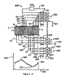
- Embodiment 500 is an apparatus for conducting an endothermic reaction, with the chemical reaction performed in reactors external to the rotary module.
- the PSA cycle pattern is shown in the lower part of Fig. 8.
- An example application is ammonia dissociation to generate reducing gas as hydrogen.
- Reactors 501, 502 and 503 are interposed in conduits 78, 76 and 70 supplying gas to the first valve face 7. If desired, only one reactor (e.g. 501) could be provided.
- a feed gas containing a relatively more readily adsorbed reactant is supplied to a stage of heavy reflux compressor 340 by infeed conduit 504, which may as needed include a vaporizer 505 to ensure that the reactant(s) are in the vapour phase.
- Gas enriched in a more readily adsorbed reactant component is withdrawn as heavy reflux gas by conduits 80, 63 and 67 from countercurrent blowdown and exhaust compartments in the first valve face, and is thence delivered to inlet ports of heavy reflux compressor stages. The heavy reflux gas is compressed and is thereby heated by the heat of compression.
- the compressed heavy reflux gas may be further heated from an external source of higher temperature heat in heat exchanger 510, before admission to reactors 501, 502 and 503.
- T2 is typically greater than T1
- the temperature of the compressed heavy reflux gas stream entering the reactors (after heavy reflux compression and heating, and any further heating by a heat exchanger 510) will be much greater than T2 (the exit temperature of the exothermic reactors) so that the endothermic heat of reaction may be carried into the reactors as sensible heat of the reactor feed.
- the endothermic reactors may be heated externally by a furnace or by other means known in the art.
- a purified stream of gas enriched in the less readily adsorbed product components is delivered at approximately the upper pressure by product delivery conduit 520.
- This stream would be hydrogen and nitrogen, completely purified of ammonia, in the example of ammonia dissociation.
- the present invention provides the important advances of 100% conversion of the feed, delivery of a purified product, and practicable operation of the catalytic reactor at much reduced temperature compared to the prior art, because the reactant is concentrated over the catalyst.
- Embodiment 600 is an apparatus for conducting an endothermic reaction, with the chemical reaction performed within the rotary module which itself is a heat exchange reactor.
- An example application is steam methane reforming to produce hydrogen from natural gas.
- a steam reforming catalyst e.g. nickel or a platinum group metal supported on alumina
- a high temperature carbon dioxide sorbent are supported in the adsorbers 3.
- the carbon dioxide sorbent may be based on potasssium carbonate promoted hydrotalcite as developed by J.R. Hufton, S.G. Mayorga and S. Sircar ("Sorption Enhanced Reaction Process for Hydrogen Production", AIChEJ 45, 248 (1999)), or another high temperature carbon dioxide sorbent likewise effective in the presence of high steam partial pressure.
- This sorbent has good working capacity for carbon dioxide in the temperature range of 400o C to 500o C.
- the working temperature of the adsorbers may desirably be near the upper end of the temperature range of 400o C to 500o C, and T1 and T2 may be substantially the same temperature or moderately different with T2 > T1.
- the feed mixture of desulphurized natural gas and steam is introduced at inlet 601 of multistage feed compressor 603.
- the compressed feed mixture is delivered at successively increasing pressures by conduits 70, 76 and 78 to the first valve face 7 at T1 after heating by heater 605 and recuperator 606.
- the feed gas mixture On entering the adsorbers 3, the feed gas mixture contacts the catalyst which stimulates reaction to hydrogen and carbon oxides.
- the reacting gas mixture simultaneously contacts the sorbent which withdraws carbon dioxide, thus driving the further reaction of methane with steam to produce hydrogen and the simultaneous reaction of carbon monoxide with steam to produce more hydrogen and carbon dioxide abstracted by the sorbent.
- Heat is provided to the strongly endothermic reaction by heat exchange within the adsorber, and in part from the exothermic heat of adsortion on the sorbent.
- product gas delivered through second valve face 8 to conduit 25 will be hydrogen containing steam, a minor concentration of unconverted methane, and only trace amounts of carbon dioxide and carbon monoxide.
- the majority portion (other than a fraction for light reflux) of the product in conduit 25 is withdrawn through steam condenser 610 and then delivered from conduit 611 as product for subsequent further purification e.g. by pressure swing adsorption at substantially ambient temperature if required.
- Hydrogen-rich gas from conduits 25, 33, 37 and 41 is expanded as light reflux gas through multistage expander 350 cooperating with heat exchanger 311. Low pressure steam may be added to this gas particularly at the lower pressure by purge stream infeed conduit 615 to assist the purge step.
- Exhaust gas rich in carbon dioxide is withdrawn from valve face 7 at successively lower pressures during countercurrent blowdown and purge steps through conduits 80, 63 and 67. These streams are cooled in recuperator 606 to assist preheating the feed, and then further cooled by heat exchanger 620.
- the carbon dioxide exhaust streams are then expanded or compressed as desired for delivery (after catalytic combustion to recover residual energy value from any slip of methane, carbon monoxide and hydrogen) as a second product stream of pure carbon dioxide or for disposal to atmosphere.
- the exhaust gas from conduits 80, 63 and 67 is compressed by multistage compressor 622 and delivered as the second product by conduit 623. This embodiment allows the lower pressure of the process to be subatmospheric if the first stage 624 of compressor 622 is operating as a vacuum pump.
- Heat must be supplied to the reactive adsorbers 3 in order to provide the endothermic heat of reaction.
- This heat of reaction is less than the endothermic requirement for conventional steam reforming processes, because the more endothermic reaction branch producing carbon monoxide is suppressed by carbon dioxide sorption in the present process.
- a substantial fraction (estimated to be about 25 %) of the endothermic requirement during the higher pressure production step is provided by the exothermic heat of carbon dioxide sorption, while this heat of sorption must of course be provided to the adsorbers 3 during carbon dioxide desorption at lower pressures.
- Some or all of the endothermic heat requirement may be provided as sensible heat provided to the incoming feed gas by heat exchangers 605 and 606, and to the incoming light reflux and purge gases by heat exchanger 311.
- a high axial thermal conductivity of the adsorbers is most desirable to improve heat transfer between the reaction zone in the adsorbers and external heat exchangers 605, 606 and 311.
- a high solid phase heat capacity is desirable within the reactive adsorbers 3 to provide some heat storage and reduce reaction temperature swings as the endothermic reation rate will be highest during the higher pressure production step of the cycle.
- Use of a metallic foil or mesh support for the catalyst and sorbent in adsorbers 3 will provide the desired enhancements of axial thermal conductivity and solid phase heat capacity.
- the heat demand of heat exchangers 605 and 311 may be made up by combustion of residual fuel components in the second product delivered by conduit 623. This fuel may be supplemented by methane either from the feedstock or else recovered as low pressure tail gas from downstream final purification of the product hydrogen delivered from conduit 611.
- Some or all of the endothermic heat requirement may alternatively be provided within adsorbers 3 by admitting a fraction of oxygen or air to purge stream infeed conduit 615 so that partial catalytic combustion of fuel components (particularly unreacted methane) takes place during the purge step.
- This is an "autothermal reforming" process option.
- Direct combustion heat release during the purge step at the lower pressure will of course assist carbon dioxide desorption, while storing the remaining heat in the solid matrix of the adsorbers to provide endothermic heat of reaction during the next production step at the higher pressure.
- heat may be provided by transverse heat transfer through extended heat exchange surfaces constituting the walls of adsorbers 3.
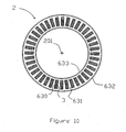
- Rotary module 2 is shown in Fig. 10, in the view corresponding to section 204 - 205 of Fig. 4, and in a simplified configuration suitable for heat exchange to the adsorbers within the rotor 2.
- the adsorbers 3 are depicted as rectangular flat packs of laminated flat sheets.
- each adsorber is contained in a jacket 630 whose external surfaces contact heat exchange channels 631, in turn bounded by walls 632 and 633.
- Heat exchange in channels 631 may in general be achieved by any means, including radiant heating, sensible heat transfer from hot flue gas, latent heat transfer from condensing vapors, sensible heat transfer from liquid metals, etc.
- the direction of fluid flow may be either substantially parallel or transverse to the process flow direction within the adsorbers 3, or a combination thereof.
- Baffles may be used to reverse the direction of heat exchange fluid flow along the length or width of the adsorbers.
- FIG. 10 shows a single annular ring of adsorbers in rotor 2, more complicated arrays (e.g. including two or more annular rings of adsorbers) may be considered within the invention.
- Fig. 11 shows a detailed cross section of a single adsorber 3 within its jacket 630.
- Adsorber 3 is a parallel pack of flat sheets 640, here supporting both the catalyst and the adsorbent in contact with the flow channels 641 defined by spacers 642 between each adjacent pair of sheets 640.
- the jacket 630 includes side walls 651 and 652 parallel to the sheets 640, and edge walls 653 and 654 terminating the edges of sheets 640.
- the sheets 640 may in principle be comprised of any reinforcement material compatible with reacting gas species and with the operating temperatures, e.g. metal foil, metal mesh, woven or nonwoven fabrics of glass or mineral fibers, or mineral or glass fiber papers.
- metal foils or wire cloth are highly preferred.
- a mixture of catalyst (e.g. nickel on alumina support) and the carbon dioxide sorbent may readily be coated on a metallic support to form sheet 640, either with inorganic binders or self-bound by the sorbent.
- Spacers 642 may be provided as narrow metal strips parallel to the flow direction in order to define channels 641, or alternatively may be formed by etching the channels through metal foil by photolithographic techniques.
- Jacket 630 may then be fabricated by diffusion bonding a stack of metal foils, which are alternatingly those coated with sorbent and catalyst, and those etched to form the longitudinal flow channels 641.
- the edges of metal foils from both the sorbent/catalyst coated sheets and the spacers are extended through the edge walls which will be formed by bonding the foils together with plates forming the side walls in fluid sealing contact.
Landscapes
- Chemical & Material Sciences (AREA)
- Engineering & Computer Science (AREA)
- Analytical Chemistry (AREA)
- General Chemical & Material Sciences (AREA)
- Oil, Petroleum & Natural Gas (AREA)
- Chemical Kinetics & Catalysis (AREA)
- Separation Of Gases By Adsorption (AREA)
- Organic Low-Molecular-Weight Compounds And Preparation Thereof (AREA)
- Physical Or Chemical Processes And Apparatus (AREA)
Abstract
Description
Fig. 2 shows the PSA cycle undergone sequentially by each of the "N"
The
Either when the
To light
Section 200 B is an adsorber wheel configuration for the embodiment of Fig. 4, at section 204 - 205. The adsorber configuration is similar to a radial flow geometry shown in copending U.S. Patent Application No. 08/995,906. Here, "N" = 72. The
Claims (63)
- A process for conducting a chemical reaction which has at least one gas phase reactant component and at least one gas phase product component, while performing separations by pressure swing adsorption of the product component from the reactant component over an adsorbent material on which one of the reactant and the product components is a more readily adsorbed component and the other is a less readily adsorbed component under increase of pressure, comprising:wherein at least one of the catalyst and the adsorbent material is supported on a plurality of support sheets separated by spacers defining flow paths between adjacent sheets.(a) introducing a feed gas containing the reactant component into a reaction space containing a catalyst to catalyze the chemical reaction (301, 401, 501, 3),(b) conducting the reaction within the reaction space so as to obtain a gas mixture containing the reactant and the product components,(c) supplying gas to a plurality of flow paths (4) extending between first and second valve faces (7, 8) in a rotor (2) at incrementally increasing pressures from a lower pressure to an upper pressure of the process,(d) withdrawing gas from each flow path at incrementally decreasing pressures from the higher pressure to the lower pressure of the process,(e) contacting the adsorbent material (3) with the gas mixture containing the reactant and the product components in the flow paths to separate the reactant component from the product component, and(f) rotating the rotor so as to establish cyclic fluid communicator for each of the flow paths through the first and second valve faces in a cyclic sequence to establish flow in each flow path directed from the first valve face to the second valve face at substantially the upper pressure, and to establish flow in each flow path directed from the second valve face to the first valve face at substantially the lower pressure,
- The process of Claim 1, wherein the catalyst is supported on the support sheets.
- The process of Claim 1, wherein the sheets are provided in a laminated parallel passage structure.
- The process of Claim 1, in which the reactant component is the less readily adsorbed component, and the withdrawing step further comprises withdrawing a gas enriched in the more readily adsorbed component from adjacent the first valve face.
- The process of Claim 4, in which the withdrawing step further comprises withdrawing gas enriched in the more readily adsorbed component from the first valve face, compressing that gas to an increased pressure, and refluxing the gas to the first valve face and thence the flow paths at the increased pressure, so as to increase the concentration of the more readily adsorbed component adjacent the first valve face.
- The process of Claim 4, in which the reaction is exothermic.
- The process of Claim 6, in which a first reactant component is hydrogen; a second reactant component is nitrogen, and the product component is ammonia.
- The process of Claim 6, in which a first reactant is hydrogen, a second reactant component is carbon monoxide, and the product component is methanol.
- The process of Claim 6, in which a first reactant component is hydrogen, a second reactant component is carbon monoxide, and the product component is hydrocarbon which is a liquid at ambient temperature.
- The process of Claim 6, in which a first reactant component is methane, a second reactant component is oxygen, and the product component is a higher hydrocarbon.
- The process of Claim 10, in which a first reactant component in methane, a second reactant component is oxygen, and the product component is ethylene.
- The process of Claim 1, in which the reactant component is the more readily adsorbed component, and the withdrawing step further comprises withdrawing a product enriched in the less readily adsorbed component from adjacent the second valve face.
- The process of Claim 12, in which the withdrawing step further comprises withdrawing gas enriched in the less readily adsorbed component from the second valve face, expanding that gas to a reduced pressure not less than the lower pressure, and refluxing that gas to the second valve face and thence the flow paths at the reduced pressure, so as to increase the concentration of the less readily adsorbed component adjacent the second valve face.
- The process of Claim 4, in which the reaction is endothermic.
- The process of Claim 14, in which the reactant component is ammonia, a first product component is hydrogen, and a second product component is nitrogen.
- The process of Claim 14, in which a first reactant component is methanol, a first product component is hydrogen, and a second product component is carbon monoxide.
- The process of Claim 14, in which a first reactant component is methanol, a second reactant component is water vapour, a first product component is hydrogen, and a second product component is carbon dioxide.
- The process of Claim 1, further comprising maintaining the temperature of the flow path adjacent the first valve approximately at a first temperature, and maintaining the temperature of the flow path adjacent the second valve face approximately at a second temperature.
- The process of Claim 18, further comprising maintaining the first temperature to be greater than the second temperature, and exchanging heat between the gas mixture in the flow paths and solid material with heat capacity disposed along the flow paths.
- The process of Claim 18, further comprising maintaining the second temperature to be greater than the first temperature.
- The process of Claim 1, further comprising two or more reaction spaces containing the catalyst.
- The process of Claim 1, further comprising the step of conducting heat between extended heat transfer surfaces in the rotor and the flow paths intermediately between the first and second valve faces.
- The process of Claim 14, further comprising the step of conducting heat to the flow paths from a heat transfer fluid externally contacting heat exchange surfaces in the rotor.
- The process of Claim 14, further comprising the step of admitting air or oxygen and providing heat in the flow paths by catalytic combustion of a reactant component within the flow paths.
- The process of Claim 14, wherein the reactant component comprises a first component which is a hydrocarbon, such as methane, and a second component, comprising steam, and wherein the product component comprises a strongly adsorbed component, which is carbon dioxide, and a component, which is hydrogen, and wherein the adsorbent material is selective for carbon dioxide in the presence of steam at elevated temperature.
- The process of Claim 25 further comprising the step of providing a nickel catalyst in the flow paths.
- The process of Claim 25 further comprising the step of providing a platinum group catalyst in the flow paths.
- The process of Claim 25 in which the first and second reactant components are introduced to the first valve face at substantially the upper pressure while hydrogen is delivered from the second valve face, and carbon dioxide is delivered from the first valve face at substantially the lower pressure.
- The process of Claim 26 in which steam is admitted to the second valve face is a lower pressure so as to assist purge.
- The process of Claim 25 in which air or oxygen is admitted to the second valve face at the lower pressure so as to assist purge while providing heat to the flow paths for the endothermic reaction.
- A rotary module for conducting a chemical reaction with a gas mixture which has a gas phase reactant component and a gas phase product component and for separating the product component from the reactant component by pressure swing adsorption, one of the reactant and the product components being a more readily adsorbed component and the other being a less readily adsorbed component under pressure increase over an adsorbent material, the rotary module comprising a stator and a rotor defining an axis of rotation, the stator having a plurality of first function compartments (61, 65, 72, 75, 77, 82) that are fluidly connectable to angular sectors of a first rotary valve surface (7), and a plurality of second function compartments (87, 92, 97) that are fluidly connectable to angular sectors of a second rotary valve surface (8), the first and second rotary value surfaces being centred on the axis of rotation; the rotor having a plurality of adsorber elements (3) having adsorbent material, the adsorber elements defining angularly spaced flow paths between the first rotary valve surface and the second rotary valve surface; and a reaction space (301, 401, 501, 3) having a catalyst for catalyzing the chemical reaction, the reaction space communicating with the flow paths; the rotor being rotatable about the axis of rotation to establish fluid communication between each first function compartment and each adsorber element through the first rotary valve surface, and to establish fluid communication between each second function compartment and each adsorber element through the second rotary valve surface, such that the pressure in each adsorber element cycles between an upper pressure and a lower pressure, and wherein at least one of the catalyst and the adsorbent material is supported on a plurality of support sheets separated by spacers defining passageways between adjacent sheets.
- The rotary module of Claim 31, wherein the function compartments also include a plurality of pressurization compartments for subjecting the flow paths to a plurality of incremental pressure increases between the upper and lower pressures.
- The rotary module of Claim 32, wherein the pressurization compartments include feed pressurization compartments (72, 75, 77) opening into the first rotary valve surface for delivering the gas mixture to the flow paths at incrementally different pressures intermediate between the upper and lower pressures.
- The rotary module of Claim 32 or 33, wherein the pressurization compartments include light reflux return compartments (92) opening into the second rotary valve surface (93) for delivering gas enriched in a less readily adsorbed component to the flow paths at a plurality of incrementally different pressures.
- The rotary module of any one of Claims 31 to 34, wherein the function compartments also include a plurality of blowdown compartments (82, 61, 65) for subjecting the flow paths to a plurality of incremental pressure decreases between the upper and lower pressures.
- The rotary module of Claim 35, wherein the blowdown compartments include light reflux exit compartments (92) opening into the second stator valve surface for removing gas enriched in a less readily adsorbed component as cocurrent blowdown from the flow paths at a plurality of incrementally different pressures.
- The rotary module of Claim 35 or 36, wherein the blowdown compartments include countercurrent blowdown compartments opening into the first stator valve surface for removing gas enriched in a more readily adsorbed component from the flow paths at a plurality of incrementally different pressures.
- The rotary module of any one of Claims 31 to 37, wherein each function compartment is shaped to provide uniform gas flow through the first or second rotary valve face.
- The rotary module of any one of Claims 31 to 38, wherein each of the function compartments simultaneously communicates with at least two angularly spaced adsorber elements so as to provide uniform gas flow at a steady pressure through each of the function compartments.
- The rotary module of any one of Claims 31 to 39, wherein the adsorbent material is supported on the plurality of support sheets and the passageways defined between adjacent sheets define the flow paths.
- The rotary module of any one of Claims 31 to 39, wherein the adsorbent material is supported in the plurality of sheets, the sheets being laminated with the spacers therebetween, and the flow paths are established by the spacers between adjacent pairs of the sheets.
- The rotary module of any one of Claims 31 to 41, further comprising fluid sealing means (130, 131) cooperating with the stator to limit fluid leakage between function compartments in each of the first and second rotary valve sealing faces, and to prevent fluid leakage from or into each of the first and second rotary valve faces.
- The rotary module of Claim 42, wherein the rotor has a first rotor face for engaging the fluid sealing means in the first rotary valve surface and a second rotor face for engaging the fluid sealing means in the second rotary valve surface.
- The rotary module of any one of Claims 31 to 43, wherein the plurality of sheets comprise a plurality of adsorber sheets (282), each said sheet including a reinforcement material, an adsorbent material deposited therein, a binder for securing the adsorbent material, and a spacer (284) provided between each adjacent pair of adsorbent sheets for providing a flow path therebetween.
- The rotary module of Claim 44, wherein the reinforcement material is selected from a mineral or glass fiber matrix such as a woven or non-woven glass fiber scrim, a metal wire matrix such as a wire mesh screen, or a metal foil such as an anodized aluminum foil.
- The rotary module of any one of Claims 31 to 45, wherein the adsorbent material comprises a zeolite.
- The rotary module of any one of Claims 44 to 46, wherein the reaction space is a zone of each adsorber element with a heterogeneous catalyst contacting the flow paths therein.
- The rotary module of any one of Claims 31 to 47, in which the composition of the adsorbent material is selected to be different in each of multiple zones along the flow paths between the first and second ends.
- The rotary module of Claim 48, in which the adsorbent material in at least one the zones is active as a heterogeneous catalyst.
- The rotary module of any one of Claims 31 to 49, with the rotor having an annular volume containing the adsorber elements, with the flow direction being axial with respect to the axis of rotation, and with the first rotor face being a circular end surface of the rotor and the second rotor face being a circular end surface of the rotor, the first and second rotor faces being substantially normal to the axis of the rotation.
- The rotary module of any one of Claims 31 to 49, with the rotor having an annular volume containing the adsorber elements, with the flow direction being substantially radial with respect to the axis of rotation, and with the first rotor face being an external cylindrical surface of the rotor and the second rotor face being an internal cylindrical surface of the rotor.
- The rotary module of any one of Claim 41, wherein the catalyst is supported on at least one of the sheets.
- The rotary module of Claim 41, wherein the catalyst is supported on plural sheets.
- The rotary module of any one of Claims 31 to 53, in which the adsorber element is contained in a jacket with heat transfer surfaces to contact an external heat transfer fluid.
- The rotary module of Claim 54, in which the reinforcement material is metallic and is in thermal conduction contact to the jacket.
- The rotary module of Claim 54, in which the reinforcement material is a metal foil and wherein the spacer between each adjacent pair of adsorbent sheets is a metal foil with the flow paths etched therein according to a photolithographic pattern, and the jacket is in part formed by diffusion bonding of the adjacent edges of the adsorbent sheet foils and the interleaved spacer foils to achieve fluid sealing integrity.
- An apparatus including a rotary module according to any one of Claims 31 to 56 further comprising compression and expansion means cooperating with a feed function compartment to generate gas flow in each flow path directed from the first end to the second end of the flow path at the upper pressure, and cooperating with an exhaust function compartment to generate gas flow in each flow path directed from the second end to the first end of the flow path at the lower pressure, the reaction space communicating with the flow paths.
- The apparatus of Claim 57, further comprising means to provide the reactant component to the apparatus (20, 70, 71, 22, 76), and to deliver the product component from the apparatus (88, 87, 86, 25).
- The apparatus of Claim 57 or 58, in which the reaction space (301) is within a flow path of the rotary module, and each such flow path has a similar reaction space therein.
- The apparatus of any one of Claims 57 to 59, comprising two or more reaction spaces containing the catalyst.
- The apparatus of any one of Claims 57 to 60, with compressor means for withdrawing gas enriched in the more readily adsorbed component from the first valve face, compressing that gas into an increased pressure, and refluxing that gas to the first valve face and thence the flow paths at the increased pressure, so as to increase the concentration of the more readily adsorbed component adjacent the first valve face.
- The apparatus of any one of Claims 57 - 60, with pressure let-down means (30, 34, 38, 42) for withdrawing gas enriched in the less readily adsorbed component from the second valve face, expanding that gas to a reduced pressure not less than the lower pressure, and refluxing that gas to the second valve face and thence the flow paths at the reduced pressure, so as to increase the concentration of the more readily adsorbed component adjacent the second valve face.
- The rotary module of Claim 31, wherein the catalyst is supported on said plurality of sheets, the sheets being contained in the reaction space.
Applications Claiming Priority (5)
| Application Number | Priority Date | Filing Date | Title |
|---|---|---|---|
| CA2274301 | 1999-06-10 | ||
| CA002274301A CA2274301A1 (en) | 1999-06-10 | 1999-06-10 | Chemical reactor with pressure swing adsorption |
| CA2274300 | 1999-06-10 | ||
| CA2274300 | 1999-06-10 | ||
| PCT/CA2000/000694 WO2000076629A1 (en) | 1999-06-10 | 2000-06-09 | Chemical reactor with pressure swing adsorption |
Publications (2)
| Publication Number | Publication Date |
|---|---|
| EP1187668A1 EP1187668A1 (en) | 2002-03-20 |
| EP1187668B1 true EP1187668B1 (en) | 2004-09-08 |
Family
ID=25681000
Family Applications (1)
| Application Number | Title | Priority Date | Filing Date |
|---|---|---|---|
| EP00938400A Expired - Lifetime EP1187668B1 (en) | 1999-06-10 | 2000-06-09 | Chemical reactor with pressure swing adsorption |
Country Status (7)
| Country | Link |
|---|---|
| US (2) | US7250150B1 (en) |
| EP (1) | EP1187668B1 (en) |
| JP (1) | JP5188663B2 (en) |
| AT (1) | ATE275435T1 (en) |
| AU (1) | AU5381300A (en) |
| DE (1) | DE60013595T2 (en) |
| WO (1) | WO2000076629A1 (en) |
Families Citing this family (69)
| Publication number | Priority date | Publication date | Assignee | Title |
|---|---|---|---|---|
| DE60013595T2 (en) | 1999-06-10 | 2005-09-15 | Questair Technologies, Inc. | CHEMICAL REACTOR WITH PRESSURE CHANGE ADSORPTION |
| WO2005053831A2 (en) * | 2003-11-26 | 2005-06-16 | Cabot Corporation | Fuel reformer catalyst and absorbent materials |
| US7384621B2 (en) | 2004-04-19 | 2008-06-10 | Texaco Inc. | Reforming with hydration of carbon dioxide fixing material |
| GB0504622D0 (en) * | 2005-03-05 | 2005-04-13 | Accentus Plc | Catalytic reactors |
| US7763098B2 (en) * | 2005-11-18 | 2010-07-27 | Xebec Adsorption Inc. | Rapid cycle syngas pressure swing adsorption system |
| CA2667467C (en) * | 2006-10-27 | 2015-03-24 | Questair Technologies Inc. | Compact pressure swing reformer |
| MY154251A (en) | 2007-11-12 | 2015-05-29 | Exxonmobil Upstream Res Co | Methods of generating and utility gas |
| CA2721724C (en) | 2008-04-30 | 2016-06-28 | Exxonmobil Upstream Research Company | Method and apparatus for removal of oil from utility gas stream |
| US8413655B2 (en) * | 2008-06-10 | 2013-04-09 | Micropore, Inc. | Adsorbents and inhalation devices |
| US7854794B2 (en) * | 2008-07-28 | 2010-12-21 | Barone Michael R | Rotary valve element for twin bed alternative treatment systems |
| US8052777B2 (en) * | 2009-06-29 | 2011-11-08 | Uop Llc | Vessel, system, and process for minimizing unequal flow distribution |
| US8187369B2 (en) * | 2009-09-18 | 2012-05-29 | General Electric Company | Sorbent activation plate |
| WO2011094296A1 (en) * | 2010-01-26 | 2011-08-04 | Micropore, Inc. | Adsorbent system for removal of gaseous contaminants |
| WO2011149640A1 (en) | 2010-05-28 | 2011-12-01 | Exxonmobil Upstream Research Company | Integrated adsorber head and valve design and swing adsorption methods related thereto |
| US8632627B2 (en) | 2010-08-10 | 2014-01-21 | General Electric Company | Gas dehydration system with desiccant transporter |
| WO2012051524A1 (en) | 2010-10-14 | 2012-04-19 | Micropore, Inc. | Adsorbent cartridge assembly with end cap |
| TWI495501B (en) | 2010-11-15 | 2015-08-11 | Exxonmobil Upstream Res Co | Kinetic fractionators, and cycling processes for fractionation of gas mixtures |
| WO2012100157A1 (en) | 2011-01-20 | 2012-07-26 | Saudi Arabian Oil Company | Direct densification method and system utilizing waste heat for on-board recovery and storage of co2 from motor vehicle internal combustion engine exhaust gases |
| WO2012100165A1 (en) | 2011-01-20 | 2012-07-26 | Saudi Arabian Oil Company | Οn-board recovery and storage of c02 from motor vehicle exhaust gases |
| WO2012100182A1 (en) | 2011-01-20 | 2012-07-26 | Saudi Arabian Oil Company | Membrane separation method and system utilizing waste heat for on-board recovery and storage of co2 from motor vehicle internal combustion engine exhaust gases |
| US9581062B2 (en) | 2011-01-20 | 2017-02-28 | Saudi Arabian Oil Company | Reversible solid adsorption method and system utilizing waste heat for on-board recovery and storage of CO2 from motor vehicle internal combustion engine exhaust gases |
| CN103429339B (en) | 2011-03-01 | 2015-06-10 | 埃克森美孚上游研究公司 | Apparatus and system with closed adsorbent contactor and swing adsorption process associated therewith |
| EP2680948A4 (en) | 2011-03-01 | 2015-05-06 | Exxonmobil Upstream Res Co | Apparatus and systems having a rotary valve assembly and swing adsorption processes related thereto |
| US9162175B2 (en) | 2011-03-01 | 2015-10-20 | Exxonmobil Upstream Research Company | Apparatus and systems having compact configuration multiple swing adsorption beds and methods related thereto |
| CA2842928A1 (en) | 2011-03-01 | 2012-11-29 | Exxonmobil Upstream Research Company | Apparatus and systems having a rotary valve assembly and swing adsorption processes related thereto |
| EP2680954B1 (en) * | 2011-03-01 | 2018-09-12 | Exxonmobil Upstream Research Company | Methods of removing contaminants from a hydrocarbon stream by pressure swing adsorption and related apparatus and systems |
| US9017457B2 (en) | 2011-03-01 | 2015-04-28 | Exxonmobil Upstream Research Company | Apparatus and systems having a reciprocating valve head assembly and swing adsorption processes related thereto |
| WO2012118758A1 (en) | 2011-03-01 | 2012-09-07 | Exxonmobil Upstream Research Company | Methods of removing contaminants from a hydrocarbon stream by swing adsorption and related apparatus and systems |
| US8728218B2 (en) * | 2011-09-15 | 2014-05-20 | Corning Incorporated | Sorbent substrates for CO2 capture and methods for forming the same |
| US9266054B2 (en) | 2012-04-24 | 2016-02-23 | Micropore, Inc. | Durable adsorbent material and adsorbent packs and method of making same |
| US8808426B2 (en) | 2012-09-04 | 2014-08-19 | Exxonmobil Research And Engineering Company | Increasing scales, capacities, and/or efficiencies in swing adsorption processes with hydrocarbon gas feeds |
| US9034078B2 (en) | 2012-09-05 | 2015-05-19 | Exxonmobil Upstream Research Company | Apparatus and systems having an adsorbent contactor and swing adsorption processes related thereto |
| EP2722093B1 (en) | 2012-10-17 | 2016-08-17 | General Electric Technology GmbH | Oxy fuel boiler system with CO2-capture unit and method of operating |
| WO2016014232A1 (en) | 2014-07-25 | 2016-01-28 | Exxonmobil Upstream Research Company | Apparatus and system having a valve assembly and swing adsorption processes related thereto |
| AU2015347232B2 (en) | 2014-11-11 | 2018-02-01 | Exxonmobil Upstream Research Company | High capacity structures and monoliths via paste imprinting |
| AU2015361102B2 (en) | 2014-12-10 | 2018-09-13 | Exxonmobil Research And Engineering Company | Adsorbent-incorporated polymer fibers in packed bed and fabric contactors, and methods and devices using same |
| AU2015370106B2 (en) | 2014-12-23 | 2019-01-03 | Exxonmobil Upstream Research Company | Structured adsorbent beds, methods of producing the same and uses thereof |
| WO2016186726A1 (en) | 2015-05-15 | 2016-11-24 | Exxonmobil Upstream Research Company | Apparatus and system for swing adsorption processes related thereto |
| CA2979869C (en) | 2015-05-15 | 2019-12-03 | Exxonmobil Upstream Research Company | Apparatus and system for swing adsorption processes related thereto comprising mid-bed purge systems |
| PL3108953T3 (en) * | 2015-06-25 | 2022-10-10 | Ateliers François | Method for compressing and drying a gas |
| PL3316989T3 (en) * | 2015-07-02 | 2019-11-29 | Solvay | Process for producing sodium carbonate/bicarbonate |
| CA2996139C (en) | 2015-09-02 | 2021-06-15 | Exxonmobil Upstream Research Company | Process and system for swing adsorption using an overhead stream of a demethanizer as purge gas |
| US10124286B2 (en) | 2015-09-02 | 2018-11-13 | Exxonmobil Upstream Research Company | Apparatus and system for swing adsorption processes related thereto |
| EA201891041A1 (en) | 2015-10-27 | 2018-09-28 | Эксонмобил Апстрим Рисерч Компани | DEVICE AND SYSTEM FOR PROCESSES OF SHORT-CYCLE ADSORPTION HAVING A VARIETY VARIETY |
| CA3002648A1 (en) | 2015-10-27 | 2017-05-04 | Exxonmobil Upstream Research Company | Apparatus and system for swing adsorption processes related thereto having a plurality of valves |
| JP6615373B2 (en) | 2015-10-27 | 2019-12-04 | エクソンモービル アップストリーム リサーチ カンパニー | Apparatus and system for swing adsorption process with active controlled feed poppet valve and passively controlled product valve |
| US10744449B2 (en) | 2015-11-16 | 2020-08-18 | Exxonmobil Upstream Research Company | Adsorbent materials and methods of adsorbing carbon dioxide |
| JP2019508245A (en) | 2016-03-18 | 2019-03-28 | エクソンモービル アップストリーム リサーチ カンパニー | Apparatus and system for swing adsorption process |
| WO2017209860A1 (en) | 2016-05-31 | 2017-12-07 | Exxonmobil Upstream Research Company | Apparatus and system for swing adsorption processes |
| EP3463620A1 (en) | 2016-05-31 | 2019-04-10 | ExxonMobil Upstream Research Company | Apparatus and system for swing adsorption processes |
| US10434458B2 (en) | 2016-08-31 | 2019-10-08 | Exxonmobil Upstream Research Company | Apparatus and system for swing adsorption processes related thereto |
| US10603626B2 (en) | 2016-09-01 | 2020-03-31 | Exxonmobil Upstream Research Company | Swing adsorption processes using zeolite structures |
| US10328382B2 (en) | 2016-09-29 | 2019-06-25 | Exxonmobil Upstream Research Company | Apparatus and system for testing swing adsorption processes |
| JP7021226B2 (en) | 2016-12-21 | 2022-02-16 | エクソンモービル アップストリーム リサーチ カンパニー | Self-supporting structure with foamed geometry and active material |
| JP7021227B2 (en) | 2016-12-21 | 2022-02-16 | エクソンモービル アップストリーム リサーチ カンパニー | Self-supporting structure with active material |
| CN107861145B (en) * | 2017-10-20 | 2023-06-16 | 苏州热工研究院有限公司 | A continuous monitoring system for radioactive inert gas in ambient air |
| US11331620B2 (en) | 2018-01-24 | 2022-05-17 | Exxonmobil Upstream Research Company | Apparatus and system for swing adsorption processes |
| US11413567B2 (en) | 2018-02-28 | 2022-08-16 | Exxonmobil Upstream Research Company | Apparatus and system for swing adsorption processes |
| CN108717286B (en) * | 2018-05-25 | 2020-07-21 | 杭州天利空分设备制造有限公司 | Double-controller control method |
| US10745276B2 (en) * | 2018-06-29 | 2020-08-18 | Praxair Technology, Inc. | Tail gas heating within PSA surge tank |
| JP7158078B2 (en) | 2018-07-09 | 2022-10-21 | 上海深城環保設備工程有限公司 | Gas adsorption separation device and its application |
| US10730006B2 (en) * | 2018-08-14 | 2020-08-04 | Air Products And Chemicals, Inc. | Port separation for rotary bed PSA |
| US11318410B2 (en) | 2018-12-21 | 2022-05-03 | Exxonmobil Upstream Research Company | Flow modulation systems, apparatus, and methods for cyclical swing adsorption |
| DE102019107440A1 (en) * | 2019-03-22 | 2020-09-24 | Otto-Von-Guericke-Universität Magdeburg | Solid reactor, system and method for separating carbon dioxide |
| US11376545B2 (en) | 2019-04-30 | 2022-07-05 | Exxonmobil Upstream Research Company | Rapid cycle adsorbent bed |
| WO2021071755A1 (en) | 2019-10-07 | 2021-04-15 | Exxonmobil Upstream Research Company | Adsorption processes and systems utilizing step lift control of hydraulically actuated poppet valves |
| WO2021076594A1 (en) | 2019-10-16 | 2021-04-22 | Exxonmobil Upstream Research Company | Dehydration processes utilizing cationic zeolite rho |
| CN112129041A (en) * | 2020-10-02 | 2020-12-25 | 朱启民 | Medical oxygen generator of continuous efficient filtration formula |
| CN120305823B (en) * | 2025-06-17 | 2025-08-22 | 上海森桓新材料科技有限公司 | Isotope separation system and isotope separation method |
Family Cites Families (53)
| Publication number | Priority date | Publication date | Assignee | Title |
|---|---|---|---|---|
| US3231492A (en) | 1962-05-16 | 1966-01-25 | Universal Oil Prod Co | Fluid-solid contacting process |
| US3176446A (en) | 1963-05-27 | 1965-04-06 | Svenskaflakfabriken Ab | Ceramic gas conditioner |
| US4224499A (en) * | 1978-10-20 | 1980-09-23 | General Electric Company | Laser welding aluminum to copper |
| US4273743A (en) | 1978-11-02 | 1981-06-16 | Texaco Inc. | Combination chemical plant and Brayton-cycle power plant |
| US4224299A (en) | 1978-11-02 | 1980-09-23 | Texaco Inc. | Combination chemical plant and Brayton-cycle power plant |
| US4273473A (en) * | 1979-03-13 | 1981-06-16 | Regal Tool & Rubber Co., Inc. | Shock absorbing column |
| US4354859A (en) | 1981-08-06 | 1982-10-19 | Union Carbide Corporation | Enhanced gas separation by selective adsorption |
| IL63630A (en) | 1981-08-21 | 1985-01-31 | Ram Lavie | Process for the manufacture of ammonia |
| US4452612A (en) | 1982-09-22 | 1984-06-05 | Cubemco, Inc. | Separation and purification of gases and vapors by continuous pressure-swing adsorption |
| US4801308A (en) | 1983-10-03 | 1989-01-31 | Keefer Bowie | Apparatus and process for pressure swing adsorption separation |
| DE3481686D1 (en) | 1983-10-03 | 1990-04-26 | Keefer Bowie | METHOD AND APPARATUS FOR GAS SEPARATION AND SYNTHESIS. |
| US4702903A (en) | 1983-10-03 | 1987-10-27 | Keefer Bowie | Method and apparatus for gas separation and synthesis |
| US4816121A (en) | 1983-10-03 | 1989-03-28 | Keefer Bowie | Gas phase chemical reactor |
| US4530705A (en) | 1984-04-16 | 1985-07-23 | Firey Joseph C | Cyclic gas separator |
| GB8524025D0 (en) | 1985-09-30 | 1985-11-06 | Shell Int Research | Chemical equilibrium reaction |
| ATE95720T1 (en) * | 1986-06-12 | 1993-10-15 | Ici Plc | ADSORPTION PROCESS. |
| JPS6328422A (en) * | 1986-07-21 | 1988-02-06 | Nippon Kokan Kk <Nkk> | Gas adsorbing and separating device |
| JPS63166702A (en) | 1986-12-26 | 1988-07-09 | Osaka Oxygen Ind Ltd | Concentration of oxygen gas |
| US4968329A (en) | 1987-10-26 | 1990-11-06 | Keefer Bowie | Pressure swing adsorption for concentration of a gas component |
| US4946479A (en) | 1987-10-28 | 1990-08-07 | Daikin Industries, Ltd. | Apparatus for solvent recovery |
| FR2633847B1 (en) | 1988-07-08 | 1991-04-19 | Air Liquide | PROCESS FOR TREATING A GAS MIXTURE BY ADSORPTION |
| CA2016045C (en) | 1990-05-04 | 1994-08-16 | Quest Air Gases Inc. | Gas separation by pressure swing adsorption |
| US5082473A (en) | 1990-07-23 | 1992-01-21 | Keefer Bowie | Extraction and concentration of a gas component |
| US5096469A (en) | 1990-07-23 | 1992-03-17 | Keefer Bowie | Adsorptive gas separator with inertial energy exchange |
| FR2667801B1 (en) * | 1990-10-11 | 1992-12-04 | Air Liquide | PROCESS AND EQUIPMENT FOR SEPARATION BY ADSORPTION OF AT LEAST ONE CONSTITUENT OF A GASEOUS MIXTURE. |
| FR2672818B1 (en) | 1991-02-20 | 1993-04-23 | Air Liquide | PROCESS FOR THE PRODUCTION OF OXYGEN BY ADSORPTION. |
| AU647617B2 (en) | 1991-05-09 | 1994-03-24 | Mitsubishi Jukogyo Kabushiki Kaisha | Gas separation system and gas recovery system |
| US5284368A (en) | 1991-07-25 | 1994-02-08 | Hans Oetiker Ag Maschinen- Und Apparatefabrik | Connection for flexible and stretchable tubes, especially silicon tubes |
| FR2684023B1 (en) | 1991-11-26 | 1994-01-14 | Air Liquide | PROCESS FOR PRODUCING A GAS WITH A SUBSTANTIAL OXYGEN CONTENT. |
| FR2689785B1 (en) * | 1992-04-13 | 1994-05-20 | Air Liquide | ROTARY DEVICE FOR SEPARATING BY ADSORPTION OF AT LEAST ONE CONSTITUENT OF A GASEOUS MIXTURE. |
| US5256172A (en) | 1992-04-17 | 1993-10-26 | Keefer Bowie | Thermally coupled pressure swing adsorption |
| LU88160A1 (en) | 1992-08-18 | 1993-10-27 | Fernande Schartz | METHOD AND DEVICE FOR SEPARATING GAS BY SELECTIVE VARIABLE PRESSURE ADSORPTION |
| US5330561A (en) | 1992-11-16 | 1994-07-19 | Air Products And Chemicals, Inc. | Extended vacuum swing adsorption process |
| US5827496A (en) | 1992-12-11 | 1998-10-27 | Energy And Environmental Research Corp. | Methods and systems for heat transfer by unmixed combustion |
| US5487775A (en) | 1994-05-09 | 1996-01-30 | The Boc Group, Inc. | Continuous pressure difference driven adsorption process |
| US5411578A (en) | 1994-05-10 | 1995-05-02 | Air Products And Chemicals, Inc. | Vacuum swing adsorption process with mixed repressurization and provide product depressurization |
| FR2722426B1 (en) | 1994-07-18 | 1996-08-23 | Air Liquide | PROCESS FOR THE SEPARATION OF NITROGEN FROM A GAS MIXTURE BY ADSORPTION |
| US5449696A (en) | 1994-08-01 | 1995-09-12 | Uop | Process for methanol production using simulated moving bed reactive chromatography |
| US5523326A (en) | 1994-10-28 | 1996-06-04 | Uop | PSA process with reaction for reversible reactions |
| US5656067A (en) | 1996-02-23 | 1997-08-12 | Air Products And Chemicals, Inc. | VSA adsorption process with energy recovery |
| US6063161A (en) | 1996-04-24 | 2000-05-16 | Sofinoy Societte Financiere D'innovation Inc. | Flow regulated pressure swing adsorption system |
| US5711926A (en) | 1996-05-14 | 1998-01-27 | Knaebel; Kent S. | Pressure swing adsorption system for ammonia synthesis |
| WO1998029182A1 (en) | 1996-12-31 | 1998-07-09 | Keefer Bowie | High frequency pressure swing adsorption |
| US6056804A (en) | 1997-06-30 | 2000-05-02 | Questor Industries Inc. | High frequency rotary pressure swing adsorption apparatus |
| US7094275B2 (en) * | 1997-12-01 | 2006-08-22 | Questair Technologies, Inc. | Modular pressure swing adsorption apparatus |
| WO1999028013A2 (en) | 1997-12-01 | 1999-06-10 | Questair Technologies, Inc. | Modular pressure swing adsorption apparatus |
| US5906674A (en) * | 1997-12-16 | 1999-05-25 | The Boc Group, Inc. | Process and apparatus for separating gas mixtures |
| US6051050A (en) | 1997-12-22 | 2000-04-18 | Questor Industries Inc. | Modular pressure swing adsorption with energy recovery |
| FR2775618B1 (en) * | 1998-03-03 | 2000-05-05 | Air Liquide | ADSORBENT WITH HETEROGENEOUS EXCHANGE RATE AND PSA METHOD USING SUCH AN ADSORBENT |
| US6103143A (en) * | 1999-01-05 | 2000-08-15 | Air Products And Chemicals, Inc. | Process and apparatus for the production of hydrogen by steam reforming of hydrocarbon |
| WO2000076628A1 (en) * | 1999-06-09 | 2000-12-21 | Questair Technologies Inc. | Rotary pressure swing adsorption apparatus |
| DE60013595T2 (en) | 1999-06-10 | 2005-09-15 | Questair Technologies, Inc. | CHEMICAL REACTOR WITH PRESSURE CHANGE ADSORPTION |
| US6514319B2 (en) * | 1999-12-09 | 2003-02-04 | Questair Technologies Inc. | Life support oxygen concentrator |
-
2000
- 2000-06-09 DE DE60013595T patent/DE60013595T2/en not_active Expired - Lifetime
- 2000-06-09 EP EP00938400A patent/EP1187668B1/en not_active Expired - Lifetime
- 2000-06-09 AU AU53813/00A patent/AU5381300A/en not_active Abandoned
- 2000-06-09 JP JP2001502947A patent/JP5188663B2/en not_active Expired - Fee Related
- 2000-06-09 WO PCT/CA2000/000694 patent/WO2000076629A1/en not_active Ceased
- 2000-06-09 AT AT00938400T patent/ATE275435T1/en not_active IP Right Cessation
- 2000-06-09 US US09/591,277 patent/US7250150B1/en not_active Expired - Fee Related
-
2007
- 2007-06-13 US US11/818,303 patent/US7687044B2/en not_active Expired - Fee Related
Also Published As
| Publication number | Publication date |
|---|---|
| ATE275435T1 (en) | 2004-09-15 |
| JP2003501247A (en) | 2003-01-14 |
| DE60013595D1 (en) | 2004-10-14 |
| AU5381300A (en) | 2001-01-02 |
| EP1187668A1 (en) | 2002-03-20 |
| JP5188663B2 (en) | 2013-04-24 |
| WO2000076629A1 (en) | 2000-12-21 |
| US20070253872A1 (en) | 2007-11-01 |
| DE60013595T2 (en) | 2005-09-15 |
| US7687044B2 (en) | 2010-03-30 |
| US7250150B1 (en) | 2007-07-31 |
Similar Documents
| Publication | Publication Date | Title |
|---|---|---|
| US7687044B2 (en) | Chemical reactor with pressure swing adsorption | |
| EP1371106B1 (en) | Electrical current generation system comprising a fuel cell and a rotary pressure swing absorption unit | |
| AU763965B2 (en) | Electrical current generation system | |
| EP1500156B1 (en) | Hydrogen recycle for solid oxide fuel cell | |
| US20040197612A1 (en) | Hydrogen recycle for high temperature fuel cells | |
| US7674539B2 (en) | Systems and processes for providing hydrogen to fuel cells | |
| CA2325072A1 (en) | Gas separation for molten carbonate fuel cell | |
| US11707707B2 (en) | CO2 capture from dilute sources | |
| USRE40006E1 (en) | Flow regulated pressure swing adsorption system | |
| CA2274301A1 (en) | Chemical reactor with pressure swing adsorption | |
| CA2374439C (en) | Chemical reactor with pressure swing adsorption | |
| CA2324699A1 (en) | Carbon monoxide removal from hydrogen feed to fuel cell | |
| CA2274240C (en) | Electrical current generation system | |
| CA2324702A1 (en) | Reformate purification and heat recovery for fuel cell | |
| CA2516300A1 (en) | Hydrogen recycle for high temperature fuel cells | |
| CA2424615A1 (en) | Systems and processes for providing hydrogen to fuel cells |
Legal Events
| Date | Code | Title | Description |
|---|---|---|---|
| PUAI | Public reference made under article 153(3) epc to a published international application that has entered the european phase |
Free format text: ORIGINAL CODE: 0009012 |
|
| AK | Designated contracting states |
Kind code of ref document: A1 Designated state(s): AT BE CH CY DE DK ES FI FR GB GR IE IT LI LU MC NL PT |
|
| AX | Request for extension of the european patent |
Free format text: AL;LT;LV;MK;RO;SI |
|
| 17P | Request for examination filed |
Effective date: 20011205 |
|
| 17Q | First examination report despatched |
Effective date: 20020715 |
|
| GRAP | Despatch of communication of intention to grant a patent |
Free format text: ORIGINAL CODE: EPIDOSNIGR1 |
|
| GRAS | Grant fee paid |
Free format text: ORIGINAL CODE: EPIDOSNIGR3 |
|
| GRAA | (expected) grant |
Free format text: ORIGINAL CODE: 0009210 |
|
| AK | Designated contracting states |
Kind code of ref document: B1 Designated state(s): AT BE CH CY DE DK ES FI FR GB GR IE IT LI LU MC NL PT |
|
| PG25 | Lapsed in a contracting state [announced via postgrant information from national office to epo] |
Ref country code: CH Free format text: LAPSE BECAUSE OF FAILURE TO SUBMIT A TRANSLATION OF THE DESCRIPTION OR TO PAY THE FEE WITHIN THE PRESCRIBED TIME-LIMIT Effective date: 20040908 Ref country code: NL Free format text: LAPSE BECAUSE OF FAILURE TO SUBMIT A TRANSLATION OF THE DESCRIPTION OR TO PAY THE FEE WITHIN THE PRESCRIBED TIME-LIMIT Effective date: 20040908 Ref country code: BE Free format text: LAPSE BECAUSE OF FAILURE TO SUBMIT A TRANSLATION OF THE DESCRIPTION OR TO PAY THE FEE WITHIN THE PRESCRIBED TIME-LIMIT Effective date: 20040908 Ref country code: FI Free format text: LAPSE BECAUSE OF FAILURE TO SUBMIT A TRANSLATION OF THE DESCRIPTION OR TO PAY THE FEE WITHIN THE PRESCRIBED TIME-LIMIT Effective date: 20040908 Ref country code: LI Free format text: LAPSE BECAUSE OF FAILURE TO SUBMIT A TRANSLATION OF THE DESCRIPTION OR TO PAY THE FEE WITHIN THE PRESCRIBED TIME-LIMIT Effective date: 20040908 Ref country code: AT Free format text: LAPSE BECAUSE OF FAILURE TO SUBMIT A TRANSLATION OF THE DESCRIPTION OR TO PAY THE FEE WITHIN THE PRESCRIBED TIME-LIMIT Effective date: 20040908 |
|
| REG | Reference to a national code |
Ref country code: GB Ref legal event code: FG4D |
|
| REG | Reference to a national code |
Ref country code: CH Ref legal event code: EP |
|
| REG | Reference to a national code |
Ref country code: IE Ref legal event code: FG4D |
|
| REF | Corresponds to: |
Ref document number: 60013595 Country of ref document: DE Date of ref document: 20041014 Kind code of ref document: P |
|
| PG25 | Lapsed in a contracting state [announced via postgrant information from national office to epo] |
Ref country code: GR Free format text: LAPSE BECAUSE OF FAILURE TO SUBMIT A TRANSLATION OF THE DESCRIPTION OR TO PAY THE FEE WITHIN THE PRESCRIBED TIME-LIMIT Effective date: 20041208 Ref country code: DK Free format text: LAPSE BECAUSE OF FAILURE TO SUBMIT A TRANSLATION OF THE DESCRIPTION OR TO PAY THE FEE WITHIN THE PRESCRIBED TIME-LIMIT Effective date: 20041208 |
|
| PG25 | Lapsed in a contracting state [announced via postgrant information from national office to epo] |
Ref country code: ES Free format text: LAPSE BECAUSE OF FAILURE TO SUBMIT A TRANSLATION OF THE DESCRIPTION OR TO PAY THE FEE WITHIN THE PRESCRIBED TIME-LIMIT Effective date: 20041219 |
|
| LTIE | Lt: invalidation of european patent or patent extension |
Effective date: 20040908 |
|
| NLV1 | Nl: lapsed or annulled due to failure to fulfill the requirements of art. 29p and 29m of the patents act | ||
| REG | Reference to a national code |
Ref country code: CH Ref legal event code: PL |
|
| PG25 | Lapsed in a contracting state [announced via postgrant information from national office to epo] |
Ref country code: LU Free format text: LAPSE BECAUSE OF NON-PAYMENT OF DUE FEES Effective date: 20050609 Ref country code: CY Free format text: LAPSE BECAUSE OF FAILURE TO SUBMIT A TRANSLATION OF THE DESCRIPTION OR TO PAY THE FEE WITHIN THE PRESCRIBED TIME-LIMIT Effective date: 20050609 Ref country code: IE Free format text: LAPSE BECAUSE OF NON-PAYMENT OF DUE FEES Effective date: 20050609 |
|
| PG25 | Lapsed in a contracting state [announced via postgrant information from national office to epo] |
Ref country code: MC Free format text: LAPSE BECAUSE OF NON-PAYMENT OF DUE FEES Effective date: 20050630 |
|
| PLBE | No opposition filed within time limit |
Free format text: ORIGINAL CODE: 0009261 |
|
| STAA | Information on the status of an ep patent application or granted ep patent |
Free format text: STATUS: NO OPPOSITION FILED WITHIN TIME LIMIT |
|
| ET | Fr: translation filed | ||
| 26N | No opposition filed |
Effective date: 20050609 |
|
| REG | Reference to a national code |
Ref country code: IE Ref legal event code: MM4A |
|
| PGFP | Annual fee paid to national office [announced via postgrant information from national office to epo] |
Ref country code: IT Payment date: 20060630 Year of fee payment: 7 |
|
| PG25 | Lapsed in a contracting state [announced via postgrant information from national office to epo] |
Ref country code: PT Free format text: LAPSE BECAUSE OF NON-PAYMENT OF DUE FEES Effective date: 20050208 |
|
| PG25 | Lapsed in a contracting state [announced via postgrant information from national office to epo] |
Ref country code: IT Free format text: LAPSE BECAUSE OF NON-PAYMENT OF DUE FEES Effective date: 20070609 |
|
| REG | Reference to a national code |
Ref country code: GB Ref legal event code: 732E Free format text: REGISTERED BETWEEN 20120906 AND 20120912 |
|
| REG | Reference to a national code |
Ref country code: DE Ref legal event code: R082 Ref document number: 60013595 Country of ref document: DE Representative=s name: KADOR & PARTNER, DE |
|
| REG | Reference to a national code |
Ref country code: DE Ref legal event code: R081 Ref document number: 60013595 Country of ref document: DE Owner name: AIR PRODUCTS AND CHEMICALS, INC., US Free format text: FORMER OWNER: QUESTAIR TECHNOLOGIES, INC., BURNABY, CA Effective date: 20121113 Ref country code: DE Ref legal event code: R082 Ref document number: 60013595 Country of ref document: DE Representative=s name: KADOR & PARTNER PARTG MBB, DE Effective date: 20121113 Ref country code: DE Ref legal event code: R081 Ref document number: 60013595 Country of ref document: DE Owner name: AIR PRODUCTS AND CHEMICALS, INC., ALLENTOWN, US Free format text: FORMER OWNER: QUESTAIR TECHNOLOGIES, INC., BURNABY, CA Effective date: 20121113 Ref country code: DE Ref legal event code: R082 Ref document number: 60013595 Country of ref document: DE Representative=s name: KADOR & PARTNER PART MBB PATENTANWAELTE, DE Effective date: 20121113 Ref country code: DE Ref legal event code: R082 Ref document number: 60013595 Country of ref document: DE Representative=s name: KADOR & PARTNER, DE Effective date: 20121113 |
|
| REG | Reference to a national code |
Ref country code: FR Ref legal event code: TP Owner name: AIR PRODUCTS AND CHEMICALS, INC., US Effective date: 20121210 |
|
| REG | Reference to a national code |
Ref country code: FR Ref legal event code: PLFP Year of fee payment: 16 |
|
| REG | Reference to a national code |
Ref country code: FR Ref legal event code: PLFP Year of fee payment: 17 |
|
| REG | Reference to a national code |
Ref country code: FR Ref legal event code: PLFP Year of fee payment: 18 |
|
| PGFP | Annual fee paid to national office [announced via postgrant information from national office to epo] |
Ref country code: FR Payment date: 20170518 Year of fee payment: 18 Ref country code: GB Payment date: 20170526 Year of fee payment: 18 |
|
| PGFP | Annual fee paid to national office [announced via postgrant information from national office to epo] |
Ref country code: DE Payment date: 20170623 Year of fee payment: 18 |
|
| REG | Reference to a national code |
Ref country code: DE Ref legal event code: R119 Ref document number: 60013595 Country of ref document: DE |
|
| GBPC | Gb: european patent ceased through non-payment of renewal fee |
Effective date: 20180609 |
|
| PG25 | Lapsed in a contracting state [announced via postgrant information from national office to epo] |
Ref country code: GB Free format text: LAPSE BECAUSE OF NON-PAYMENT OF DUE FEES Effective date: 20180609 Ref country code: FR Free format text: LAPSE BECAUSE OF NON-PAYMENT OF DUE FEES Effective date: 20180630 Ref country code: DE Free format text: LAPSE BECAUSE OF NON-PAYMENT OF DUE FEES Effective date: 20190101 |