EP1187264A2 - Waterproof connector - Google Patents
Waterproof connector Download PDFInfo
- Publication number
- EP1187264A2 EP1187264A2 EP01120709A EP01120709A EP1187264A2 EP 1187264 A2 EP1187264 A2 EP 1187264A2 EP 01120709 A EP01120709 A EP 01120709A EP 01120709 A EP01120709 A EP 01120709A EP 1187264 A2 EP1187264 A2 EP 1187264A2
- Authority
- EP
- European Patent Office
- Prior art keywords
- terminal
- terminal inserting
- portions
- common wall
- waterproof
- Prior art date
- Legal status (The legal status is an assumption and is not a legal conclusion. Google has not performed a legal analysis and makes no representation as to the accuracy of the status listed.)
- Granted
Links
- 230000013011 mating Effects 0.000 claims description 7
- 230000002093 peripheral effect Effects 0.000 description 21
- 230000001154 acute effect Effects 0.000 description 2
- 230000037431 insertion Effects 0.000 description 2
- 238000003780 insertion Methods 0.000 description 2
Images


Classifications
-
- H—ELECTRICITY
- H01—ELECTRIC ELEMENTS
- H01R—ELECTRICALLY-CONDUCTIVE CONNECTIONS; STRUCTURAL ASSOCIATIONS OF A PLURALITY OF MUTUALLY-INSULATED ELECTRICAL CONNECTING ELEMENTS; COUPLING DEVICES; CURRENT COLLECTORS
- H01R13/00—Details of coupling devices of the kinds covered by groups H01R12/70 or H01R24/00 - H01R33/00
- H01R13/46—Bases; Cases
- H01R13/52—Dustproof, splashproof, drip-proof, waterproof, or flameproof cases
- H01R13/5205—Sealing means between cable and housing, e.g. grommet
- H01R13/5208—Sealing means between cable and housing, e.g. grommet having at least two cable receiving openings
-
- F—MECHANICAL ENGINEERING; LIGHTING; HEATING; WEAPONS; BLASTING
- F16—ENGINEERING ELEMENTS AND UNITS; GENERAL MEASURES FOR PRODUCING AND MAINTAINING EFFECTIVE FUNCTIONING OF MACHINES OR INSTALLATIONS; THERMAL INSULATION IN GENERAL
- F16B—DEVICES FOR FASTENING OR SECURING CONSTRUCTIONAL ELEMENTS OR MACHINE PARTS TOGETHER, e.g. NAILS, BOLTS, CIRCLIPS, CLAMPS, CLIPS OR WEDGES; JOINTS OR JOINTING
- F16B2200/00—Constructional details of connections not covered for in other groups of this subclass
- F16B2200/10—Details of socket shapes
Definitions
- the present invention relates to a waterproof connector which does not damage a waterproof plug at a time of receiving a terminal having the waterproof plug in a terminal receiving chamber.
- a related waterproof connector is provided with a housing main body having a plurality of terminal receiving chambers, and a plurality of terminal inserting portions formed in this housing main body.
- the related waterproof connector is structured such that a terminal assembled in an electric wire and having a waterproof plug is received within the terminal receiving chamber, and the waterproof plug is closely assembled on an inner peripheral surface of the terminal inserting portion, whereby a waterproof plug is applied to a portion between the electric wire and the inner peripheral surface of the terminal inserting portion.
- the terminal inserting portions are formed by a tube-shaped body and are respectively extended from a plurality of terminal receiving chambers. These terminal inserting portions are integrally formed in a state that outer peripheral surfaces are in contact with each other, and are sectioned by common wall portions between the adjacent portions. Further, each of the terminal inserting portions is provided with a taper surface at an opening edge.
- a terminal is inserted to the terminal inserting portion when the terminal is assembled in the waterproof connector.
- the waterproof plug is brought into contact with the taper surface.
- the waterproof plug slides along the taper surface in a contact manner so as to be guided within the terminal inserting portion.
- the terminal is received in the terminal receiving chamber, and the waterproof plug is closely attached to the inner peripheral surface of the terminal inserting portion.
- the adjacent terminal inserting portions are integrally formed in a state that the outer peripheral surfaces are in contact with each other for the purpose of making compact, a thickness of the common wall portion is made thin, and a distance between the adjacent terminal inserting portions is made short.
- the taper surfaces in the adjacent terminal inserting portions are in contact with each other on the common wall portion and an edge portion having an acute angle is formed on the common wall portion due to the taper surface.
- the waterproof plug is brought into contact with the edge portion so as to be damaged at a time when the terminal is inserted to the terminal inserting portion, so that there is a risk that it is impossible to waterproof between the electric wire and the terminal inserting portion.
- An object of the present invention is to provide a waterproof connector which can prevent a waterproof plug from being damaged by an edge portion at a time of inserting a terminal to a terminal inserting portion so as to securely waterproof between an electric wire and a terminal inserting portion, and does not reduce an operability of assembling the terminal.
- a waterproof connector comprising a housing main body having a plurality of terminal receiving chambers; a plurality of terminal inserting portions formed in the housing main body, extended from the plurality of terminal receiving chambers and to which terminals assembled in electric wires and having waterproof plugs are respectively inserted; a plurality of common wall portions respectively sectioning between adjacent portions in the plurality of terminal inserting portions; and taper surfaces respectively provided in opening edges of the plurality of terminal inserting portions and guiding the terminals to the terminal inserting portions, and maximum diameter portions of the taper surfaces in the adjacent terminal inserting portions are at least in contact on the common wall portion, wherein the waterproof connector is provided with a damage preventing portion formed in a portion in which the taper surfaces of the adjacent terminal inserting portions on the common wall portion are in contact with each other, and prevents the waterproof plug from being damaged at a time of inserting the terminals to the terminal inserting portions.
- the waterproof plugs are brought into contact with the taper surface.
- the waterproof plugs slide along the taper surface in a contact manner so as to be guided within the terminal inserting portions.
- the outer peripheral surfaces of the waterproof plugs are closely attached to the inner peripheral surfaces of the terminal inserting portions.
- the waterproof plugs are brought into contact with the common wall portion.
- the waterproof plugs can be prevented by the damage preventing portion from being damaged even when the waterproof plugs are brought into contact with the portion that the taper surfaces in the adjacent terminal inserting portions of the common wall portion are in contact with each other.
- the damage preventing portion may be constituted by a concave step portion in which an inner peripheral surface forms an acute angle with respect to the taper surface.
- the waterproof plugs are brought into contact with the common wall portion. At this time, a part of the waterproof plugs are brought into contact with the inner peripheral surface of the step portion formed on the common wall portion.
- the damage preventing portion may be formed by a curved surface connecting the taper surfaces of the adjacent terminal inserting portions to each other.
- the waterproof plugs are brought into contact with the common wall portion. At this time, a part of the waterproof plugs are brought into contact with the curved surface formed on the common wall portion.
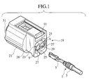
- Fig. 1 is a perspective view showing a first embodiment of a waterproof connector according to the present invention.
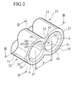
- Fig. 2 is a perspective view of a terminal inserting portion of the waterproof connector shown in Fig. 1.
- Fig. 3 is a sectional view taken along a line III-III of the terminal inserting portion shown in Fig. 2.
- Fig. 4 is a sectional view taken along a line IV-IV of the terminal inserting portion shown in Fig. 2.
- a waterproof connector comprises a housing main body 21, a plurality of terminal inserting portions 23 and 23 formed in the housing main body 21, a common wall portion 25 sectioning the respective terminal inserting portions 23 and 23, taper surfaces 27 and 27 respectively provided in opening edges of a plurality of terminal inserting portions 23 and 23, and a damage preventing portion 29 formed in the common wall portion.
- a plurality of terminal receiving chambers (not shown) are provided in parallel to each other therewithin, and a terminal 5 is received in each of a plurality of terminal receiving chambers.
- the housing 21 has a fitting portion 31 fitted to a mating housing main body (not shown) in one side, and a plurality of terminal inserting portions 23 are integrally formed in another side of the housing 21.
- a plurality of terminal inserting portions 23 and 23 are, as shown in Figs. 1 and 2, respectively formed in a tube shape, and are extended from the terminal receiving chambers so as to protrude outward from another side of the housing main body.
- These terminal inserting portions 23 and 23 are structured such that a waterproof plug 3 is closely attached to an inner peripheral surface 9 in the terminal inserting portions 23 and 23 in a state that a terminal 5 is received in the terminal receiving chamber.
- the terminal inserting portions 23 and 23 are integrally formed in a state that adjacent outer peripheral surfaces 11 are in contact with each other, and sectioned with each other by the common wall portion 25.
- the common wall portion 25 is formed so that an end surface 33 is flush with an end surface 35 of the terminal inserting portion 23.
- the terminal inserting portions 23 and 23 formed in this manner are covered by a tube-shaped wall portion 26 in a periphery of the outer peripheral surface 11.
- the taper surfaces 27 and 27 respectively formed along the opening edges of a plurality of terminal inserting portions 23 and 23 are formed by a bowl-shaped annular slant face. These taper surfaces 27 and 27 are structured such that a diameter thereof becomes gradually larger from the inner peripheral surfaces 9 and 9 of the terminal inserting portions 23 and 23 toward the opening edge sides of the terminal inserting portions 23 and 23, and form maximum diameter portions 39 having the largest diameter at the opening edges. Moreover, the taper surfaces 27 and 27 of the adjacent terminal inserting portions 23 and 23 are formed so that the maximum diameter portions 39 are in contact with each other on an end surface 33 of the common wall portion 25. A damage preventing portion 29 is provided in a portion in which the taper surfaces 27 of the adjacent terminal inserting portions 23 are in contact with each other on the end surface 33 of the common wall portion 25.
- the damage preventing portion 29 is , as shown in Figs . 2 to 4, constituted by a concave step portion 41, and is formed in a state the portion in which the taper surfaces 27 and 27 are in contact with each other on the end surface 33 of the common wall portion 25 is notched.
- the step portion 41 is connected to each of the respective taper surfaces 27 and 27 of the terminal inserting portions 23 and 23 adjacent in both sides in a width direction of the inner peripheral surface 43.
- the inner peripheral surface 43 of the step portion 41 respectively forms an obtuse angle together with the taper surfaces 27 and 27, and is constituted by a pair of slant faces 45 and 47 and a bottom surface 49.
- the slant faces 45 and 47 are, as shown in Figs. 2 and 4, formed in a flat shape, and are provided in an upper portion and a lower portion in a mating manner.
- the upper slant face 45 is structured such that one side is connected to the end surface 33 of the common wall portion 25, and another side is arranged inside the terminal inserting portion 23 with respect to the opening edge of the terminal inserting portion 23.
- the upper slant face 45 is structured such that another side is arranged to be lower with respect to one side so as to form an obtuse angle with respect to the end surface 33 of the common wall portion 25.
- the lower slant face 47 is structured such that one side is connected to the end surface 33 of the common wall portion 25, and another side is arranged inside the terminal inserting portion 23 with respect to the opening edge of the terminal inserting portion 23.
- the lower slant face 47 is structured such that another side is arranged to be upper with respect to one side so as to form an obtuse angle with respect to the end surface 33 of the common wall portion 25.
- the bottom surface 49 is formed in a flat shape, and both sides in a vertical direction are connected to the another sides of the slant faces 45 and 47 so as to respectively form the obtuse angles with respect to the slant faces 45 and 47.
- the bottom surface 49 is formed in an arc shape so that both sides in the width direction respectively profile the shapes of the terminal inserting portions 23 and 23.
- the terminal 5 is received within the terminal receiving chamber, whereby the terminal 5 is set in a state of being assembled in the housing main body 21, and thereafter, the housing main body 21 is fitted and connected to the mating housing main body (not shown).
- the terminal 5 At a time of receiving the terminal 5 in the terminal inserting portion 23, the terminal 5 is arranged near the terminal inserting portion 23, and a front end of the terminal is aligned with an opening edge of the terminal inserting portion 23. Further, a cross sectional shape of the waterproof plug 3 is coincided with the opening edge of the terminal inserting portion 23, whereby the terminal 5 is set in a positioned state.
- the waterproof plug 3 When the terminal 5 is inserted within the terminal inserting portion 23 until a predetermined position, the waterproof plug 3 is brought into contact with the taper surface 27. At this time, in the case that the positioned state of the terminal 5 is cancelled and the terminal 5 is slanted to the side of the common wall portion 25 as a whole, when the terminal 5 is inserted within the terminal inserting portion 23 until the predetermined position, the waterproof plug 3 is brought into contact with the end surface 33 of the common wall portion 25 so as to be bent, and a part of the waterproof plug 3 is brought into contact with the inner peripheral surface 43 of the step portion 41.
- the waterproof plug 3 When the waterproof plug 3 is brought into contact with the end surface 33 of the common wall portion 25, the waterproof plug 3 becomes in a state of bridging over an opening port 51 of the step portion 41.
- a force in an inserting direction is applied to the terminal 5
- a part of the waterproof plug 3 is bent and the bent portion slides along the slant faces 45 and 47 in a contact manner from the opening 51 so as to expand out within the step portion 41.
- the slant faces 45 and 47 form an obtuse angle with respect to the common wall portion 25, and the slant faces 45 and 47 and the bottom surface 49 form an obtuse angle, the step portion 41 does not damage the waterproof plug 3.
- the waterproof plug 3 expanding out within the step portion 41 from the opening 51 is brought into contact with the bottom surface 49 so as to restrict an insertion of the terminal 5 into the terminal inserting portion 23.
- the waterproof plug 3 slides along the taper surface 27 in a contact manner so as to be guided within the terminal inserting portion 23, and the insertion of the terminal 5 to the terminal inserting portion 23 is guided by the taper surface 27. Accordingly, the terminal 5 is received within the terminal receiving chamber, and the waterproof plug 3 is closely attached to the inner peripheral surface 9 of the terminal inserting portion 23 and becomes in a state of assembling the terminal 5 in the housing main body 21.
- the mating housing main body (not shown) is fitted and connected to the fitting portion 31 of the housing main body 21, thereby conducting and connecting the terminal 5 of the housing main body 21 with the terminal of the mating housing main body.
- the step portion 41 is formed in the portion in which the taper surfaces 27 and 27 of the adjacent terminal inserting portions 23 and 23 on the end surface 33 of the common wall portion 25 are in contact with each other. Accordingly, in the case that the terminal 5 is slanted to the side of the common wall portion 25 as a whole, the terminal 5 is brought into contact with the inner peripheral surface 43 of the step portion 41, whereby the waterproof plug 3 is prevented from being damaged by the edge portion at a time of inserting the terminal 5 into the terminal inserting portion 23 which is caused in the related art.
- the waterproof plug 3 is closely attached to the inner peripheral surface 9 so as to waterproof between the electric wire 1 and the terminal inserting portion 23 by the waterproof plug 3.
- the step portion 41 is formed in the portion in which the taper surfaces 27 and 27 of the adjacent terminal inserting portions 23 and 23 on the end surface 33 of the common wall portion 25 are in contact with each other, it is possible to prevent the edge portion from being formed on the end surface 33 of the common wall portion 25 without reducing a size S of the taper surfaces 27 and 27 which is caused in the related art. Accordingly, in the waterproof connector 19 according to the present embodiment, it is possible to prevent an operability of assembling the terminal 5 from being reduced without reducing a guiding performance of the terminal 5 to the terminal inserting portions 23 and 23 by the taper surface 27 and 27.
- the structure is made such that the maximum diameter portions 39 and 39 of the taper surface 27 and 27 in the adjacent terminal inserting portions 23 and 23 are in contact with each other on the end surface 33 of the common wall portion 25, however, the structure is made such that portions between the maximum diameter portions 39 and 39 of the taper surfaces 27 and 27 and minimum diameter portions are in contact with each other on the end surface 33 of the common wall portion 25.
- the damage preventing portion 29 is formed by the concave step portion 41, however, may be formed by a curved surface.
- Fig. 5 is a sectional view showing a second embodiment of a waterproof connector 19 according to the present invention.
- the waterproof connector 19 comprises a housing main body 21, a plurality of terminal inserting portions 23 formed in the housing main body 21, a common wall portion 25 sectioning the respective terminal inserting portions 23, taper surfaces 27 respectively provided in opening edges of a plurality of terminal inserting portions 23, and a damage preventing portion 30 formed in the common wall portion 23.
- the damage preventing portion 30 is constituted by a curved surface 53, as shown in Fig. 5.
- the curved surface 53 is structured such that both sides in a width direction are connected to the taper surfaces 27 and 27 of the adjacent terminal inserting portions 23 and 23, and connect the taper surfaces 27 and 27 to each other.
- the curved surface 53 is structured such that a middle portion in the width direction is formed on substantially the same plane as the end surface 33 of the common wall portion 23, and both sides in the vertical direction are connected to the end surface 33 of the common wall portion 25.
- the terminal 5 is set to a state of being assembled in the housing main body 21, and thereafter, the housing main body 21 is fitted and connected to the mating housing main body (not shown).
- the terminal 5 When assembling the terminal 5 in the housing main body 21, the terminal 5 is inserted to the terminal inserting portion 23 so as to receive the terminal 5 within the terminal receiving chamber.
- the waterproof plug 3 When the terminal 5 is inserted within the terminal inserting portion 23 until a predetermined position, the waterproof plug 3 is brought into contact with the taper surface 27. At this time, in the case that the terminal 5 is slanted to the side of the common wall portion 25 as a whole, when the terminal 5 is inserted within the terminal inserting portion 23 until the predetermined position, the waterproof plug 3 is brought into contact with the end surface 33 of the common wall portion 25, and a part of the waterproof plug 3 is brought into contact with a middle portion of the curved surface 53.
- the waterproof plug 3 when a force is applied to the terminal 5 in an inserting direction to the terminal inserting portion 23, the waterproof plug 3 is bent and slides along the curved surface 53 in a contact manner. Accordingly, the terminal 5 moves in a center side of the terminal inserting portion 23 as a whole, and the waterproof plug 3 is brought into contact with the taper surface 27. In this state, when inserting the terminal 5 within the terminal inserting portion 23, the waterproof plug 3 slides along the taper surface 27 in a contact manner so as to be guided within the terminal inserting portion 23, whereby the terminal 5 is received within the terminal receiving chamber, and the waterproof plug 3 is closely attached to the inner peripheral surface 9 of the terminal inserting portion 23 and becomes in a state of assembling the terminal 5 in the housing main body 21.
- the curved surface 53 is formed in the portion in which the taper surfaces 27 and 27 of the adjacent terminal inserting portions 23 and 23 on the end surface 33 of the common wall portion 25 are in contact with each other. Accordingly, in the case that the terminal 5 is inserted to the terminal inserting portion 23 in a state of being slanted to a side of the common wall portion 25 as a whole, the terminal 5 is brought into contact with the curved surface 53 and it is possible to prevent the waterproof plug 3 from being damaged by the edge portion at a time of inserting the terminal 5 to the terminal inserting portion 23 which is caused in the related art.
- the waterproof plug 3 is closely attached to the inner peripheral surface 9 of the terminal inserting portion 23 so as to waterproof between the electric wire 1 and the terminal inserting portion 23 by the waterproof plug 3.
- the curved surface 53 is formed in the portion in which the taper surfaces 27 and 27 of the adjacent terminal inserting portions 23 and 23 on the end surface 33 of the common wall portion 25 are in contact with each other, it is possible to prevent the edge portion from being formed on the end surface 33 of the common wall portion 25 without reducing a size S of the taper surfaces 27 and 27 which is caused in the related art. Accordingly, it is possible to prevent an operability of assembling the terminal 5 from being reduced without reducing a guiding performance of the terminal 5 to the terminal inserting portions 23 and 23 by the taper surface 27 and 27.
- the waterproof connector 19 in the case that the terminal is inserted in a state of being slanted to the side of the common wall portion 25 as a whole, a part of the waterproof plug 3 is brought into contact with the middle portion of the curved surface 53 so as to be bent and slide along the curved surface 53 in a contact manner. Accordingly, the terminal 5 moves to the center side of the terminal inserting portion 23 as a whole and the waterproof plug 3 is guided within the terminal inserting portion 23 by the taper surface 27.
Landscapes
- Connector Housings Or Holding Contact Members (AREA)
Abstract
Description
Claims (7)
- A waterproof connector comprising:a plurality of terminal receiving chambers;a housing main body having the plurality of terminal receiving chambers;a plurality of terminal inserting portions formed in the housing main body, extended from the plurality of terminal receiving chambers and to which terminals assembled in electric wires and having waterproof plugs are respectively inserted;a plurality of common wall portions respectively sectioning between adjacent portions in the plurality of terminal inserting portions; andtaper surfaces respectively provided in opening edges of the plurality of terminal inserting portions and guiding the terminals to the terminal inserting portions, andmaximum diameter portions of the taper surfaces in the adjacent terminal inserting portions are at least in contact on the common wall portion, whereinthe waterproof connector is provided with a damage preventing portion formed in a portion in which the taper surfaces of the adjacent terminal inserting portions on the common wall portion are in contact with each other, and prevents the waterproof plug from being damaged at a time of inserting the terminals to the terminal inserting portions.
- A waterproof connector according to claim 1, whereinthe damage preventing portion is formed by a concave step portion.
- A waterproof connector according to claim 1 or 2, whereinthe damage preventing portion is formed by a curved surface connecting the taper surfaces of the adjacent terminal inserting portions to each other.
- A waterproof connector according to claim 1,2 or 3, whereina fitting portion fitting to a mating housing main body is provided in an opposite side to the terminal inserting portion, in the housing main body.
- A waterproof connector according to claim 2, whereinthe concave step portion of the damage preventing portion comprisesa pair of slant faces formed on a flat surface; anda bottom surface formed on a plane connected to the pair of slant faces, andthe pair of slant faces form an obtuse angle with respect to the common wall portion and the bottom surface.
- A waterproof connector according to claim 5, whereinthe pair of slant faces and the bottom surface form an obtuse angle with respect to the taper surface.
- A waterproof connector according to any one of the preceding claims, whereinthe taper surface is formed by a bowl-shaped annular slant face.
Applications Claiming Priority (2)
| Application Number | Priority Date | Filing Date | Title |
|---|---|---|---|
| JP2000267647A JP3825238B2 (en) | 2000-09-04 | 2000-09-04 | Waterproof connector |
| JP2000267647 | 2000-09-04 |
Publications (3)
| Publication Number | Publication Date |
|---|---|
| EP1187264A2 true EP1187264A2 (en) | 2002-03-13 |
| EP1187264A3 EP1187264A3 (en) | 2002-10-30 |
| EP1187264B1 EP1187264B1 (en) | 2004-07-14 |
Family
ID=18754538
Family Applications (1)
| Application Number | Title | Priority Date | Filing Date |
|---|---|---|---|
| EP01120709A Expired - Lifetime EP1187264B1 (en) | 2000-09-04 | 2001-09-04 | Waterproof connector |
Country Status (4)
| Country | Link |
|---|---|
| US (1) | US6589078B2 (en) |
| EP (1) | EP1187264B1 (en) |
| JP (1) | JP3825238B2 (en) |
| DE (1) | DE60104251T2 (en) |
Families Citing this family (4)
| Publication number | Priority date | Publication date | Assignee | Title |
|---|---|---|---|---|
| JP5169359B2 (en) * | 2008-03-21 | 2013-03-27 | 株式会社デンソー | Power cable connector |
| JP2015204260A (en) * | 2014-04-16 | 2015-11-16 | 矢崎総業株式会社 | Rubber plug fixing structure |
| JP6461077B2 (en) * | 2016-12-16 | 2019-01-30 | 矢崎総業株式会社 | connector |
| JP6922838B2 (en) * | 2018-05-16 | 2021-08-18 | 住友電装株式会社 | connector |
Family Cites Families (9)
| Publication number | Priority date | Publication date | Assignee | Title |
|---|---|---|---|---|
| US4832615A (en) * | 1986-07-07 | 1989-05-23 | Amp Incorporated | Sealed connector having unitary molded housing |
| JP2659295B2 (en) * | 1991-09-12 | 1997-09-30 | 矢崎総業株式会社 | Automatic supply method of rubber plug for waterproof connector and rubber stopper for waterproof connector |
| US5266045A (en) * | 1991-10-28 | 1993-11-30 | Yazaki Corporation | Waterproof connector |
| JPH0794235A (en) * | 1993-09-20 | 1995-04-07 | Sumitomo Wiring Syst Ltd | Electric wire holder for waterproof connector |
| JP3106903B2 (en) | 1995-04-27 | 2000-11-06 | 住友電装株式会社 | Waterproof connector |
| JPH09106851A (en) * | 1995-10-09 | 1997-04-22 | Yazaki Corp | Waterproof connector |
| JPH11219758A (en) | 1998-01-30 | 1999-08-10 | Yazaki Corp | Multi-pole shield connector and mating shield connector |
| JP3535034B2 (en) * | 1999-03-29 | 2004-06-07 | 矢崎総業株式会社 | Waterproof connector |
| JP2000348815A (en) * | 1999-06-03 | 2000-12-15 | Yazaki Corp | Waterproof connector and method of assembling the waterproof connector |
-
2000
- 2000-09-04 JP JP2000267647A patent/JP3825238B2/en not_active Expired - Fee Related
-
2001
- 2001-08-29 US US09/940,650 patent/US6589078B2/en not_active Expired - Lifetime
- 2001-09-04 EP EP01120709A patent/EP1187264B1/en not_active Expired - Lifetime
- 2001-09-04 DE DE60104251T patent/DE60104251T2/en not_active Expired - Lifetime
Also Published As
| Publication number | Publication date |
|---|---|
| DE60104251D1 (en) | 2004-08-19 |
| EP1187264B1 (en) | 2004-07-14 |
| DE60104251T2 (en) | 2005-08-25 |
| JP3825238B2 (en) | 2006-09-27 |
| JP2002075520A (en) | 2002-03-15 |
| US6589078B2 (en) | 2003-07-08 |
| US20020028108A1 (en) | 2002-03-07 |
| EP1187264A3 (en) | 2002-10-30 |
Similar Documents
| Publication | Publication Date | Title |
|---|---|---|
| EP1536527B1 (en) | A watertight connector and method of assembling it | |
| EP0600419B1 (en) | Electrical socket terminal | |
| US5975964A (en) | Female terminal fitting | |
| JP3320378B2 (en) | Electrical connector | |
| US7329154B2 (en) | Electrical connector having terminals arranged with narrow pitch | |
| US7470153B2 (en) | Audio jack with improved contact arrangement | |
| US5775932A (en) | Electrical connector | |
| JPH1040996A (en) | Terminal fitting | |
| US4898548A (en) | Connector assembly | |
| US5282757A (en) | Connector | |
| JP3674767B2 (en) | connector | |
| JP2001185273A (en) | Female-type contact and electrical connector using the same | |
| JPH10223303A (en) | Rubber stopper for waterproof connector | |
| US5860836A (en) | Contact which enables reliable discrimination of its orientation and connector using the same | |
| US6231393B1 (en) | Electrical connector | |
| US7938677B1 (en) | Electrical jumper with retaining arrangements | |
| KR100897014B1 (en) | Electric connector | |
| EP1187264B1 (en) | Waterproof connector | |
| EP0701299B1 (en) | Female electrical terminal | |
| US6217356B1 (en) | Electrical terminal with arc arresting region | |
| US20010000499A1 (en) | Switch-equipped coaxial connector | |
| US6328606B1 (en) | High density electrical connector system | |
| US5951326A (en) | Connector and connector assembling method | |
| EP1063732A1 (en) | Press pin ground | |
| US6485312B1 (en) | Electrical connector assembly |
Legal Events
| Date | Code | Title | Description |
|---|---|---|---|
| PUAI | Public reference made under article 153(3) epc to a published international application that has entered the european phase |
Free format text: ORIGINAL CODE: 0009012 |
|
| 17P | Request for examination filed |
Effective date: 20010904 |
|
| AK | Designated contracting states |
Kind code of ref document: A2 Designated state(s): AT BE CH CY DE DK ES FI FR GB GR IE IT LI LU MC NL PT SE TR |
|
| AX | Request for extension of the european patent |
Free format text: AL;LT;LV;MK;RO;SI |
|
| PUAL | Search report despatched |
Free format text: ORIGINAL CODE: 0009013 |
|
| AK | Designated contracting states |
Kind code of ref document: A3 Designated state(s): AT BE CH CY DE DK ES FI FR GB GR IE IT LI LU MC NL PT SE TR |
|
| AX | Request for extension of the european patent |
Free format text: AL;LT;LV;MK;RO;SI |
|
| 17Q | First examination report despatched |
Effective date: 20030606 |
|
| AKX | Designation fees paid |
Designated state(s): DE FR GB |
|
| GRAP | Despatch of communication of intention to grant a patent |
Free format text: ORIGINAL CODE: EPIDOSNIGR1 |
|
| GRAS | Grant fee paid |
Free format text: ORIGINAL CODE: EPIDOSNIGR3 |
|
| GRAA | (expected) grant |
Free format text: ORIGINAL CODE: 0009210 |
|
| AK | Designated contracting states |
Kind code of ref document: B1 Designated state(s): DE FR GB |
|
| REG | Reference to a national code |
Ref country code: GB Ref legal event code: FG4D |
|
| REF | Corresponds to: |
Ref document number: 60104251 Country of ref document: DE Date of ref document: 20040819 Kind code of ref document: P |
|
| REG | Reference to a national code |
Ref country code: IE Ref legal event code: FG4D |
|
| ET | Fr: translation filed | ||
| PLBE | No opposition filed within time limit |
Free format text: ORIGINAL CODE: 0009261 |
|
| STAA | Information on the status of an ep patent application or granted ep patent |
Free format text: STATUS: NO OPPOSITION FILED WITHIN TIME LIMIT |
|
| REG | Reference to a national code |
Ref country code: IE Ref legal event code: MM4A |
|
| 26N | No opposition filed |
Effective date: 20050415 |
|
| PGFP | Annual fee paid to national office [announced via postgrant information from national office to epo] |
Ref country code: GB Payment date: 20150902 Year of fee payment: 15 Ref country code: DE Payment date: 20150902 Year of fee payment: 15 |
|
| REG | Reference to a national code |
Ref country code: FR Ref legal event code: PLFP Year of fee payment: 16 |
|
| PGFP | Annual fee paid to national office [announced via postgrant information from national office to epo] |
Ref country code: FR Payment date: 20160816 Year of fee payment: 16 |
|
| REG | Reference to a national code |
Ref country code: DE Ref legal event code: R119 Ref document number: 60104251 Country of ref document: DE |
|
| GBPC | Gb: european patent ceased through non-payment of renewal fee |
Effective date: 20160904 |
|
| PG25 | Lapsed in a contracting state [announced via postgrant information from national office to epo] |
Ref country code: GB Free format text: LAPSE BECAUSE OF NON-PAYMENT OF DUE FEES Effective date: 20160904 Ref country code: DE Free format text: LAPSE BECAUSE OF NON-PAYMENT OF DUE FEES Effective date: 20170401 |
|
| REG | Reference to a national code |
Ref country code: FR Ref legal event code: ST Effective date: 20180531 |
|
| PG25 | Lapsed in a contracting state [announced via postgrant information from national office to epo] |
Ref country code: FR Free format text: LAPSE BECAUSE OF NON-PAYMENT OF DUE FEES Effective date: 20171002 |