EP1186942A2 - Wavelength conversion apparatus - Google Patents
Wavelength conversion apparatus Download PDFInfo
- Publication number
- EP1186942A2 EP1186942A2 EP01121608A EP01121608A EP1186942A2 EP 1186942 A2 EP1186942 A2 EP 1186942A2 EP 01121608 A EP01121608 A EP 01121608A EP 01121608 A EP01121608 A EP 01121608A EP 1186942 A2 EP1186942 A2 EP 1186942A2
- Authority
- EP
- European Patent Office
- Prior art keywords
- light
- wavelength conversion
- polarization
- optical axis
- wavelength
- Prior art date
- Legal status (The legal status is an assumption and is not a legal conclusion. Google has not performed a legal analysis and makes no representation as to the accuracy of the status listed.)
- Withdrawn
Links
- 238000006243 chemical reaction Methods 0.000 title claims abstract description 354
- 230000010287 polarization Effects 0.000 claims abstract description 428
- 230000003287 optical effect Effects 0.000 claims description 356
- 238000000926 separation method Methods 0.000 claims description 135
- 239000000463 material Substances 0.000 claims description 30
- 238000010586 diagram Methods 0.000 description 18
- 239000002131 composite material Substances 0.000 description 17
- 239000013307 optical fiber Substances 0.000 description 15
- 230000001419 dependent effect Effects 0.000 description 9
- 230000000694 effects Effects 0.000 description 8
- 229910009372 YVO4 Inorganic materials 0.000 description 7
- 239000013078 crystal Substances 0.000 description 7
- 230000005540 biological transmission Effects 0.000 description 5
- 239000006185 dispersion Substances 0.000 description 4
- 230000005684 electric field Effects 0.000 description 4
- 238000005516 engineering process Methods 0.000 description 3
- 239000012780 transparent material Substances 0.000 description 3
- 229910003334 KNbO3 Inorganic materials 0.000 description 1
- 229910003327 LiNbO3 Inorganic materials 0.000 description 1
- 229910012463 LiTaO3 Inorganic materials 0.000 description 1
- 239000011248 coating agent Substances 0.000 description 1
- 238000000576 coating method Methods 0.000 description 1
- 239000000835 fiber Substances 0.000 description 1
- 239000000203 mixture Substances 0.000 description 1
Images



Classifications
-
- G—PHYSICS
- G02—OPTICS
- G02F—OPTICAL DEVICES OR ARRANGEMENTS FOR THE CONTROL OF LIGHT BY MODIFICATION OF THE OPTICAL PROPERTIES OF THE MEDIA OF THE ELEMENTS INVOLVED THEREIN; NON-LINEAR OPTICS; FREQUENCY-CHANGING OF LIGHT; OPTICAL LOGIC ELEMENTS; OPTICAL ANALOGUE/DIGITAL CONVERTERS
- G02F1/00—Devices or arrangements for the control of the intensity, colour, phase, polarisation or direction of light arriving from an independent light source, e.g. switching, gating or modulating; Non-linear optics
- G02F1/35—Non-linear optics
- G02F1/353—Frequency conversion, i.e. wherein a light beam is generated with frequency components different from those of the incident light beams
-
- G—PHYSICS
- G02—OPTICS
- G02F—OPTICAL DEVICES OR ARRANGEMENTS FOR THE CONTROL OF LIGHT BY MODIFICATION OF THE OPTICAL PROPERTIES OF THE MEDIA OF THE ELEMENTS INVOLVED THEREIN; NON-LINEAR OPTICS; FREQUENCY-CHANGING OF LIGHT; OPTICAL LOGIC ELEMENTS; OPTICAL ANALOGUE/DIGITAL CONVERTERS
- G02F1/00—Devices or arrangements for the control of the intensity, colour, phase, polarisation or direction of light arriving from an independent light source, e.g. switching, gating or modulating; Non-linear optics
- G02F1/01—Devices or arrangements for the control of the intensity, colour, phase, polarisation or direction of light arriving from an independent light source, e.g. switching, gating or modulating; Non-linear optics for the control of the intensity, phase, polarisation or colour
- G02F1/09—Devices or arrangements for the control of the intensity, colour, phase, polarisation or direction of light arriving from an independent light source, e.g. switching, gating or modulating; Non-linear optics for the control of the intensity, phase, polarisation or colour based on magneto-optical elements, e.g. exhibiting Faraday effect
- G02F1/093—Devices or arrangements for the control of the intensity, colour, phase, polarisation or direction of light arriving from an independent light source, e.g. switching, gating or modulating; Non-linear optics for the control of the intensity, phase, polarisation or colour based on magneto-optical elements, e.g. exhibiting Faraday effect used as non-reciprocal devices, e.g. optical isolators, circulators
-
- G—PHYSICS
- G02—OPTICS
- G02F—OPTICAL DEVICES OR ARRANGEMENTS FOR THE CONTROL OF LIGHT BY MODIFICATION OF THE OPTICAL PROPERTIES OF THE MEDIA OF THE ELEMENTS INVOLVED THEREIN; NON-LINEAR OPTICS; FREQUENCY-CHANGING OF LIGHT; OPTICAL LOGIC ELEMENTS; OPTICAL ANALOGUE/DIGITAL CONVERTERS
- G02F1/00—Devices or arrangements for the control of the intensity, colour, phase, polarisation or direction of light arriving from an independent light source, e.g. switching, gating or modulating; Non-linear optics
- G02F1/35—Non-linear optics
- G02F1/353—Frequency conversion, i.e. wherein a light beam is generated with frequency components different from those of the incident light beams
- G02F1/3542—Multipass arrangements, i.e. arrangements to make light pass multiple times through the same element, e.g. using an enhancement cavity
-
- G—PHYSICS
- G02—OPTICS
- G02F—OPTICAL DEVICES OR ARRANGEMENTS FOR THE CONTROL OF LIGHT BY MODIFICATION OF THE OPTICAL PROPERTIES OF THE MEDIA OF THE ELEMENTS INVOLVED THEREIN; NON-LINEAR OPTICS; FREQUENCY-CHANGING OF LIGHT; OPTICAL LOGIC ELEMENTS; OPTICAL ANALOGUE/DIGITAL CONVERTERS
- G02F1/00—Devices or arrangements for the control of the intensity, colour, phase, polarisation or direction of light arriving from an independent light source, e.g. switching, gating or modulating; Non-linear optics
- G02F1/35—Non-linear optics
- G02F1/353—Frequency conversion, i.e. wherein a light beam is generated with frequency components different from those of the incident light beams
- G02F1/3544—Particular phase matching techniques
- G02F1/3548—Quasi phase matching [QPM], e.g. using a periodic domain inverted structure
-
- G—PHYSICS
- G02—OPTICS
- G02F—OPTICAL DEVICES OR ARRANGEMENTS FOR THE CONTROL OF LIGHT BY MODIFICATION OF THE OPTICAL PROPERTIES OF THE MEDIA OF THE ELEMENTS INVOLVED THEREIN; NON-LINEAR OPTICS; FREQUENCY-CHANGING OF LIGHT; OPTICAL LOGIC ELEMENTS; OPTICAL ANALOGUE/DIGITAL CONVERTERS
- G02F2203/00—Function characteristic
- G02F2203/02—Function characteristic reflective
-
- G—PHYSICS
- G02—OPTICS
- G02F—OPTICAL DEVICES OR ARRANGEMENTS FOR THE CONTROL OF LIGHT BY MODIFICATION OF THE OPTICAL PROPERTIES OF THE MEDIA OF THE ELEMENTS INVOLVED THEREIN; NON-LINEAR OPTICS; FREQUENCY-CHANGING OF LIGHT; OPTICAL LOGIC ELEMENTS; OPTICAL ANALOGUE/DIGITAL CONVERTERS
- G02F2203/00—Function characteristic
- G02F2203/06—Polarisation independent
Definitions
- the present invention relates to a wavelength conversion apparatus capable of converting a wavelength of input light to another wavelength.
- wavelength division multiplexing WDM
- OTDM optical time division multiplexing
- wavelength division multiplexing optical transmission is mainstream that uses as the carrier wavelength the 1.5- ⁇ m band suitable for wavelength division multiplexing transmission.
- Examples of the related conventional art include Japanese Unexamined Patent Publication JP-A 10-213826 (1998), Japanese Unexamined Patent Publication JP-A 2000-10130 (2000), and a literature (IEICE Trans. Electron. Vol. E83-C, No. 6, pp. 869-874 (2000)).
- the nonlinear optical effect largely depends on the polarization condition of the input light and the bearing of the nonlinear optical material. For example, when a light linearly polarized in a predetermined direction passes through an optical fiber, since the light is affected by the dispersion and the like of the optical fiber, the polarization condition at the exit of the optical fiber generally cannot be identified.
- nonlinear optical materials are generally polarized light dependent in connection with wavelength conversion, when the polarization condition of the input light varies among carrier wavelengths, the wavelength conversion efficiency is inconstant, so that the intensity of the wavelength-converted output light is unstable.
- An object of the invention is to provide a wavelength conversion apparatus capable of realizing stable wavelength conversion not depending on polarization conditions of signal light.
- the invention relates to a wavelength conversion apparatus comprising:
- the wavelength conversion element is polarization dependent, namely, the wavelength conversion element can wavelength-convert the linearly polarized light component in the first direction, but cannot wavelength-convert the linearly polarized light component in a second direction perpendicular to the first direction, and by disposing the polarization rotating means behind the wavelength conversion element, when a pumped light and a signal light are input, the first-direction components of the pumped light and signal light are wavelength-converted by the wavelength conversion element, and the second-direction components perpendicular to the first direction are not wavelength-converted.
- the first-direction components which are perpendicular to the first direction of the wavelength conversion element are not wavelength-converted, and the second-direction components which are parallel to the first direction of the wavelength conversion element are wavelength-converted. Consequently, the first-direction components are wavelength-converted on the way to the reflecting element and the second-direction components are wavelength-converted on the way back, so that the composite intensity of the wavelength-converted outputs is constant. As a result, stable wavelength conversion not depending on the polarization condition of the signal light can be realized.
- the wavelength conversion apparatus comprises a wavelength selection reflecting element, disposed between the wavelength conversion element and the polarization rotating means, for selectively reflecting a pumped light.
- the wavelength selection reflecting element for selectively reflecting the pumped light between the wavelength conversion element and the polarization rotating means, when the pumped light and the signal light are input, the first-direction components of the pumped light and signal light are wavelength-converted by the wavelength conversion element, and the second-direction components perpendicular to the first direction are not wavelength-converted. Then, only the pumped light is returned to the wavelength conversion element by the wavelength selection reflecting element and the signal light passes through the wavelength selection reflecting element as it is.
- the first-direction component and the second-direction component are again rotated by 45 degrees about the optical axis by a 45-degree polarization rotating element, and pass through the wavelength selection reflecting element as they are. Then, the first-direction component of the signal light perpendicular to the first direction of the wavelength conversion element is not wavelength-converted, the second-direction component of the signal light parallel to the first direction of the wavelength conversion element is wavelength-converted, and at this time, the first-direction component of the pumped light contributes to wavelength conversion. Consequently, since the first-direction component of the pumped light can contribute to wavelength conversion on both ways, the wavelength conversion efficiency is improved. Preferably, by using a linearly polarized light in the first direction as the pumped light, the wavelength conversion efficiency can be further improved.
- the invention relates to a wavelength conversion apparatus comprising:
- wavelength conversion for each of the two linearly polarized light components is carried out, and composition of the wavelength-converted components is carried out again, so that the composite intensity of the wavelength-converted output lights is constant.
- the invention relates to a wavelength conversion apparatus comprising:
- the wavelength conversion element is polarization dependent, namely, the wavelength conversion element can wavelength-convert the linearly polarized light component in the first direction, but cannot wavelength-convert the linearly polarized light component in the second direction.
- the polarization separation element separates along the first optical axis the linearly polarized lights in the first direction with respect to the pumped light and the signal light and along the second optical axis the Linearly polarized lights in the second direction perpendicular to the first direction.
- the pumped light and the signal light traveling along the first optical axis are wavelength-converted by the wavelength conversion element.
- the polarization directions thereof become parallel to the first direction, and the pumped light and the signal light are wavelength-converted by the wavelength conversion element.
- the pumped light and the signal light traveling from the wavelength conversion element along the first optical axis when the pumped light and the signal light pass through the second 90-degree polarization rotating element, the polarization directions thereof become parallel to the second direction, and the pumped light and the signal light enter the polarization multiplexing element.
- the pumped light and the signal light traveling from the wavelength conversion element along the second optical axis enter the polarization multiplexing element as they are, and the lights along the optical axes are multiplexed. Consequently, the first-direction component is wavelength-converted on the first optical axis and the second-direction component is wavelength-converted on the second optical axis, so that the composite intensity of the wavelength-converted output lights is constant. As a result, stable wavelength conversion not depending on the polarization condition of the signal light can be realized.
- the invention relates to a wavelength conversion apparatus comprising:
- the first and second wavelength conversion elements are polarization dependent, namely, the first wavelength conversion element can wavelength-convert the linearly polarized light component in the first direction, but cannot wavelength-convert the linearly polarized light component in the second direction, and the second wavelength conversion element can wavelength-convert the linearly polarized light component in the second direction, but cannot wavelength-convert the linearly polarized light component in the first direction.
- the polarization separation element separates the pumped light and the signal light into the linearly polarized lights in the first direction and the linearly polarized lights in the second direction perpendicular to the first direction so that the linearly polarized lights in the first direction travel along the first optical axis and the linearly polarized lights in the second direction travel along the second optical axis .
- the pumped light and the signal light traveling along the first optical axis are wavelength-converted by the first wavelength conversion element.
- the pumped light and the signal light traveling along the second optical axis are wavelength-converted by the second wavelength conversion element.
- the pumped lights and the signal lights traveling from the first wavelength conversion element along the first optical axis and traveling from the second wavelength conversion element along the second optical axis are multiplexed by the polarization multiplexing element. Consequently, the first-direction component is wavelength-converted by the first wavelength conversion element, and the second-direction component is wavelength-converted by the second wavelength conversion element, so that the composite intensity of the wavelength-converted output lights is constant. As a result, stable wavelength conversion not depending on the polarization condition of the signal light can be realized.
- the invention relates to a wavelength conversion apparatus comprising:
- the wavelength conversion element is polarization dependent, namely, the wavelength conversion element can wavelength-convert the linearly polarized light component in the first direction, but cannot wavelength-convert the linearly polarized light component in the second direction.
- the polarization separation element separates along the first optical axis the linearly polarized lights in the first direction, with respect to the pumped light and the signal light and separates along the second optical axis the linearly polarized lights in the second direction perpendicular to the first direction.
- the pumped light and the signal light traveling along the first optical axis are wavelength-converted by the wavelength conversion element.
- the polarization directions thereof become parallel to the first direction, and the pumped light and the signal light are wavelength-converted by the wavelength conversion element.
- the pumped lights, the signal lights and the output lights traveling from the wavelength conversion element along the first optical axis and the second optical axis are reflected at the reflecting element, and then, again pass through the same wavelength conversion element to be wavelength-converted.
- the pumped light, the signal light and the output light traveling along the second optical axis pass through the 90-degree polarization rotating element, so that the polarization directions thereof are made parallel to the second direction. Then, the lights enter the polarization separation element.
- the pumped lights, the signal lights and the output lights traveling along the optical axes are multiplexed by the polarization separation element.
- the first-direction component is wavelength-converted on the first optical axis and the second-direction component is wavelength-converted on the second optical axis, so that the composite intensity of the wavelength-converted output lights is constant.
- stable wavelength conversion not depending on the polarization condition of the signal light can be realized.
- the invention relates to a wavelength conversion apparatus comprising:
- the first and second wavelength conversion elements are polarization dependent, namely, the first wavelength conversion element can wavelength-convert the linearly polarized light component in the first direction, but cannot wavelength-convert the linearly polarized light component in the second direction, and the second wavelength conversion element can wavelength-convert the linearly polarized light component in the second direction, but cannot wavelength-convert the linearly polarized light in the first direction.
- the polarization separation element When the pumped light and the signal light are input to the polarization separation element disposed in front of the wavelength conversion elements, the polarization separation element separates along the first optical axis the linearly polarized lights in the first direction, with respect to the pumped light and the signal light, and along the second optical axis the linearly polarized lights in the second direction perpendicular to the first direction.
- the pumped light and the signal light traveling along the first optical axis are wavelength-converted by the first wavelength conversion element.
- the pumped light and the signal light traveling along the second optical axis are wavelength-converted by the second wavelength conversion element.
- the pumped lights and the signal lights traveling from the wavelength conversion elements along the first optical axis and the second optical axis are reflected at the reflecting element, again pass through the same wavelength conversion elements to be wavelength-converted, and then, are multiplexed by the polarization multiplexing element. Consequently, the first-direction component is wavelength-converted by the first wavelength conversion element and the second-direction component is wavelength-converted by the second wavelength conversion element, so that the composite intensity of the wavelength-converted output lights is constant. As a result, stable wavelength conversion not depending on the polarization condition of the signal light can be realized.
- the invention relates to a wavelength conversion apparatus comprising:
- the wavelength conversion element is polarization dependent, namely, the wavelength conversion element can wavelength-convert the linearly polarized light component in the first direction, but cannot wavelength-convert the linearly polarized light component in the second direction.
- the polarization separation element separates along the first optical axis the linearly polarized lights in the first direction, with respect to the pumped light and the signal light, and along the second optical axis the linearlypolarized lights in the second direction perpendicular to the first direction.
- the pumped light and the signal light traveling along the first optical axis are wavelength-converted by the wavelength conversion element.
- the pumped light and the signal light traveling along the second optical axis are not wavelength-converted.
- the pumped lights and the signal lights traveling from the wavelength conversion element along the first optical axis and the second optical axis are multiplexed by the polarization multiplexing element.
- the polarization multiplexing element separates along the second optical axis the pumped light and the signal light traveling along the first optical axis on the way to the reflecting element, and separates along the first optical axis the pumped light and the signal traveling along the second optical axis on the way back.
- the lights along the first optical axis are wavelength-converted by the wavelength conversion element, whereas the lights along the second optical axis are not wavelength-converted.
- the pumped lights and the signal lights traveling from the wavelength conversion element along the first optical axis and the second optical axis are multiplexed by the polarization separation element.
- the first-direction component is wavelength-converted on the way to the reflecting element and the second-direction component is wavelength-converted on the way back, so that the composite intensity of the wavelength-converted output lights is constant.
- stable wavelength conversion not depending on the polarization condition of the signal light can be realized.
- the invention relates to a wavelength conversion apparatus comprising:
- the wavelength conversion element is polarization dependent, namely, the wavelength conversion element can wavelength-convert the linearly polarized light component in the first direction, but cannot wavelength-convert the linearly polarized light component in the second direction.
- the polarization separation element separates along the first optical axis the linearly polarized lights in the first direction, with respect to the pumped light and the signal light, and along the second optical axis the linearly polarized lights in the seconddirection perpendicular to the first direction.
- the pumped light and the signal light traveling along the first optical axis are wavelength-converted by the wavelength conversion element.
- the polarization directions thereof become parallel to the first direction, and the pumped light and the signal light are wavelength-converted by the wavelength conversion element.
- the pumped light and the signal light traveling from the wavelength conversion element along the first optical axis pass through the second 90-degree polarization rotating element, so that the polarization directions thereof are made parallel to the second direction. Then, the lights enter the polarization multiplexing element.
- the pumped light and the signal light traveling from the wavelength conversion element along the second optical axis enter the polarization multiplexing element as they are.
- the lights along the optical axes are multiplexed.
- the polarization multiplexing element separates along the second optical axis the pumped light and the signal light traveling along the first optical axis on the way to the reflecting element, and separates along the first optical axis the pumped light and the signal light traveling along the second optical axis on the way back.
- the pumped light and the signal light traveling along the first optical axis are wavelength-converted by the wavelength conversion element, and enters the polarization separation element as they are.
- the polarization directions thereof become parallel to the first direction, and the pumped light and the signal light are wavelength-converted by the wavelength conversion element. Then, when the pumped light and the signal light pass through the first 90-degree polarization rotating element, the polarization directions thereof become parallel to the second direction, and the pumped light and the signal light enter the polarization separation element.
- the pumped lights and the signal lights traveling along the optical axes are multiplexed by the polarization separation element.
- the first-direction component and the second-direction component are wavelength-converted on both ways, so that the composite intensity of the wavelength-converted output lights is constant. As a result, stable wavelength conversion not depending on the polarization condition of the signal light can be realized.
- the invention relates to a wavelength conversion apparatus comprising:
- the first and second wavelength conversion elements are polarization dependent, namely, the first wavelength conversion element can wavelength-convert the linearly polarized light component in the first direction, but cannot wavelength-convert the linearly polarized light component in the second direction, and the second wavelength conversion element can wavelength-convert the linearly polarized light component in the second direction, but cannot wavelength-convert the linearly polarized light component in the first direction.
- the polarization separation element When the pumped light and the signal light are input to the polarization separation element disposed in front of the wavelength conversion elements, the polarization separation element separates along the first optical axis the linearly polarized lights in the first direction, with respect to the pumped light and the signal light, and along the second optical axis the linearly polarized lights in the second direction perpendicular to the first direction.
- the pumped light and the signal light traveling along the first optical axis are wavelength-converted by the first wavelength conversion element.
- the pumped light and the signal light traveling along the second optical axis are wavelength-converted by the second wavelength conversion element.
- the pumped lights and the signal lights traveling from the first wavelength conversion element along the first optical axis and traveling from the second wavelength conversion element along the second optical axis are multiplexed by the polarization multiplexing element.
- the polarization multiplexing element separates along the second optical axis the pumped light and the signal light traveling along the first optical axis on the way to the reflecting element, and along the first optical axis the pumped light and the signal light traveling along the second optical axis on the way back.
- the light along the first optical axis is wavelength-converted by the first wavelength conversion element
- the light along the second optical axis is wavelength-converted by the second wavelength conversion element.
- the pumped lights and the signal lights traveling from the first wavelength conversion element along the first optical axis and traveling from the second wavelength conversion element along the second optical axis are multiplexed by the polarization multiplexing element. Consequently, the first-direction component and the second-direction component are wavelength-converted on both ways, so that the composite intensity of the wavelength-converted output lights is constant. As a result, stable wavelength conversion not depending on the polarization condition of the signal light can be realized.
- the polarization rotating means comprises a 45-degree rotating element for rotating a polarization direction of light by 45 degrees and the reflecting element for reflecting a light having passed through the 45-degree polarization rotating element to return the light to the 45-degree polarization rotating element, and the 45-degree rotating element is disposed between the wavelength conversion element and the reflecting element.
- the light incident on the polarization rotating means can be returned to the wavelength conversion element by rotating the polarization direction of the light by 90 degrees.
- the polarization rotating means comprises a ⁇ /4 plate disposed between the reflecting element and the wavelength conversion element, and the reflecting element.
- the light incident on the polarization rotating means can be returned to the wavelength conversion element by rotating the polarization direction of the light by 90 degrees.
- the composite intensity of the wavelength-converted output lights is constant, so that stable wavelength conversion not depending on the polarization condition of the signal light can be realized.
- FIG. 1 is a block diagram showing a first embodiment of the invention.
- the wavelength conversion apparatus comprises a multiplexer 10, a light circulator 11, a wavelength conversion element 1, a Faraday rotator 22 and a reflecting mirror 20.
- the multiplexer 10 has an input port 10a to which pumped light (wavelength ⁇ p) is input and an input port 10b to which signal light (wavelength ⁇ s) is input.
- the multiplexer 10 multiplexes the pumped light and the signal light, and outputs the multiplexed lights along the same optical axis.
- the light circulator 11 outputs the light input to a port 11a to a port 11b, and outputs the light input to the port 11b to a port 11c.
- the wavelength conversion elements 1 and 2 are made of a nonlinear optical material such as LiNbO 3 (LN for short), LiTaO 3 (LT for short), KNbO 3 (KN for short) or KTiOPO 4 (KTP for short) .
- a nonlinear optical material such as LiNbO 3 (LN for short), LiTaO 3 (LT for short), KNbO 3 (KN for short) or KTiOPO 4 (KTP for short) .
- QPM quasi phase matching
- the Faraday rotator 22 rotates the polarization direction of light by 45 degrees about the optical axis in a predetermined direction.
- the reflecting mirror 20 reflects the incident light onto the same optical axis.
- the wavelength ⁇ s is set in a C band (1.53 to 1.56 ⁇ m)
- the wavelength ⁇ L is set in an L band (1.56 to 1.61 ⁇ m)
- the wavelength ⁇ p is set to 1.56 ⁇ m at the midpoint between the C band and the L band.
- a linearly polarized light in which the ratio between the x-direction component and the y-direction component is 1:1 is used as the pumped light. It is assumed that the polarization direction of the signal light varies with time and is uncertain.
- the pumped light and the signal light are multiplexed by the multiplexer 10, and pass through the wavelength conversion element 1 by way of the port 11a and the port 11b of the light circulator 11.
- the pumped light and signal light are wavelength-converted with respect to their x-direction components by the wavelength conversion element 1 polarized in the x direction to be output as a light polarized in the x direction.
- the pumped light and the signal light are not wavelength-converted with respect to the y-direction components thereof, because the y-direction components are perpendicular to the polarization direction of the wavelength conversion element 1.
- the pumped light, the signal light and the output light pass through the Faraday rotator 22, so that the polarization directions thereof are rotated by 45 degrees.
- the pumped light, the signal light and the output light are reflected at the reflecting mirror 20, and again pass through the Faraday rotator 22, so that the polarization directions thereof are further rotated by 45 degrees.
- the polarization directions are rotated by 90 degrees with respect to the directions before the lights are incident on the Faraday rotator 22.
- the pumped light, the signal light and the output light are again input to the wavelength conversion element 1.
- the x-direction components of the pumped light and the signal light which are rotated in the y direction are not wavelength-converted by the wavelength conversion element 1, whereas the y-direction components of the pumped light and the signal light which are rotated in the x direction are wavelength-converted by the wavelength conversion element 1. Consequently, the x-direction components before input are wavelength-converted on the way to the reflecting mirror 20, and the y-direction components before input are wavelength-converted on the way back.
- the wavelength-converted output light is extracted by way of the port 11b and the port 11c of the light circulator 11.
- the intensity IL of the output light does not depend on the incident polarization angle ⁇ of the signal light and is constant, so that wavelength conversion being stable even when the polarization condition of the signal light varies can be realized.
- FIG. 2 is a block diagram showing a second embodiment of the invention.
- the wavelength conversion apparatus includes a multiplexer 10, a light circulator 11, a wavelength conversion element 1, a wavelength selection reflecting mirror 21, a Faraday rotator 22 and a reflecting mirror 20.
- the multiplexer 10 has an input port 10a to which pumped light (wavelength ⁇ p) is input and an input port 10b to which signal light (wavelength ⁇ s) is input.
- the multiplexer 10 multiplexes the pumped light and the signal light, and outputs the multiplexed lights along the same optical axis.
- the light circulator 11 outputs the light input to a port 11a to a port 11b, and outputs the light input to the port 11b to a port 11c.
- the wavelength conversion element 1 is made of a nonlinear optical material such as LN, LT, KN or KTP. In this embodiment, an example is shown that uses a QPM element whose polarization direction is alternately reversed at intervals of the coherence length.
- the wavelength conversion element 1 is disposed so that the polarization direction thereof is parallel to the x direct ion.
- the wavelength selection reflecting mirror 21 comprises a dichroic mirror or the like, and has the property of reflecting the pumped light and transmitting the signal light and the output light. At this time, the larger the difference between the reflected wavelength and the transmitted wavelength is, the more excellent the obtained property is. Therefore, it is desirable to set the wavelength of the pumped light to the wavelength corresponding to the second harmonic of the fundamental wavelength.
- the Faraday rotator 22 rotates the polarization direction of light by 45 degrees about the optical axis in a predetermined direction.
- the reflecting mirror 20 reflects the incident light onto the same optical axis.
- the wavelength ⁇ s is set in the C band
- the wavelength ⁇ L is set in the L band
- the wavelength ⁇ p is set to 0.78 ⁇ m corresponding to half of 1.56 ⁇ m at the midpoint between the C band and the L band.
- a linearly polarized light in the x direction is used as the pumped light. It is assumed that the polarization direction of the signal light varies with time and is uncertain.
- the pumped light and the signal light are multiplexed by the multiplexer 10, and pass through the wavelength conversion element 1 by way of the port 11a and the port 11b of the light circulator 11.
- the x-direction components of the pumped light and the signal light are wavelength-converted to an output light polarized in the x direction by the wavelength conversion element 1 polarized in the x direction. Since the y-direction components of the pumped light and the signal light are perpendicular to the polarization direction of the wavelength conversion element 1, the y-direction components are not wavelength-converted.
- the wavelength selection reflecting mirror 21 reflects only the pumped light from the wavelength conversion element 1, and inputs the reflected pumped light again to the wavelength conversion element 1.
- the signal light and the output light pass through the wavelength selection reflecting mirror 21. Consequently, the pumped light linearly polarized in the x direction can contribute to wavelength conversion on both ways.
- the signal light and the output light pass through the Faraday rotator 22, so that the polarization directions thereof are rotated by 45 degrees. Then, the signal light and the output light are reflected at the reflecting mirror 20 and again pass through the Faraday rotator 22, so that the polarization directions thereof are further rotated by 45 degrees. With this, the polarization directions are rotated by 90 degrees with respect to the directions before the lights are incident on the Faraday rotator 22. Then, the signal light and the output light pass through the wavelength selection reflecting mirror 21, and are again input to the wavelength conversion element 1.
- the x-direction component of the signal light which is rotated in the y direction is not wavelength-converted by the wavelength conversion element 1, whereas the y-direction component of the signal light which is rotated in the x direction is wavelength-converted by the wavelength conversion element 1. Consequently, the x-direction component before input is wavelength-converted on the way to the reflecting mirror 20, and the y-direction component before input is wavelength-converted on the way back.
- the wavelength-converted output light is extracted by way of the port 11b and the port 11c of the light circulator 11.
- cascade difference frequency generation can be performed.
- the wavelength ⁇ s is set in the C band
- the wavelength ⁇ L is set in the L band
- the wavelength ⁇ p is set to 1.56 ⁇ m at the midpoint between the C band and the L band.
- the wavelength selection reflecting mirror 21 an optical element having a steeper wavelength selecting property, for example, a fiber-type filter such as a fiber Bragg grating (FBG), or a narrow-band optical coating filter.
- FBG fiber Bragg grating
- the intensity IL of the output light does not depend on the incident polarization angle ⁇ of the signal light and is constant, so that wavelength conversion being stable even when the polarization condition of the signal light varies can be realized.
- the intensity IL of the output light is twice the intensity IL of FIG. 1, so that the wavelength conversion efficiency can be further improved.
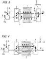
- FIG. 3 is a block diagram showing a third embodiment of the invention.
- the wavelength conversion apparatus includes a multiplexer 10, a polarization separation element 3, a wavelength conversion element 1, a polarization multiplexing element 4, and 90-degree polarization rotating elements 5 and 6.
- the multiplexer 10 has an input port 10a to which pumped light (wavelength ⁇ p) is input and an input port 10b to which signal light (wavelength ⁇ s) is input.
- the multiplexer 10 multiplexes the pumped light and the signal light, and outputs the multiplexed lights along the same optical axis.
- the wavelength conversion element 1 is made of a nonlinear optical material such as LN, LT, KN or KTP. In this embodiment, an example is shown that uses a QPM element whose polarization direction is alternately reversed at intervals of the coherence length.
- the wavelength conversion element 1 is disposed so that the polarization direction thereof is parallel to the x direction.
- the polarization separation element 3 and the polarization multiplexing element 4 are made of a material such as a birefringent optical crystal cut obliquely with respect to the crystallographic axis (for example, YVO 4 cut in a direction at an angle of 45 degrees from the c axis), and have the function of, by a beam walk-off effect, separating an incident light into the linearly polarized light in the x direction which travels along the optical axis Q1, as extraordinary light e , and the linearly polarized light in the y direction which travels along the optical axis Q2, as ordinary light o , or multiplexing the linearly polarized light in the x direction incident along the optical axis Q1 and the linearly polarized light in the y direction incident along the optical axis Q2.
- a birefringent optical crystal cut obliquely with respect to the crystallographic axis for example, YVO 4 cut in a direction at an angle of 45 degrees from the
- the 90-degree polarization rotating elements 5 and 6 comprise half-wave plates or the like, and have the function of rotating the polarization direction of the incident light by 90 degrees.
- the wavelength ⁇ s is set in the C band
- the wavelength ⁇ L is set in the L band
- the wavelength ⁇ p is set to 1.56 ⁇ m at the midpoint between the C band and the L band.
- the pumped light and the signal light are multiplexed by the multiplexer 10 and incident on the polarization separation element 3. Then, the linearly polarized lights, in the x direction, of the pumped light and the signal light are separated along the optical axis Q1 by the polarization separation element 3, are wavelength-converted to an output light polarized in the x direction by the wavelength conversion element 1 polarized in the x direction, are converted to a linearly polarized light in the y direction by the 90-degree polarization rotating element 6, and then enter the polarization multiplexing element 4.
- the linearly polarized lights, in the y direction, of the pumped light and the signal light are separated along the optical axis Q2 by the polarization separation element 3, are converted to a linearly polarized light in the x direction by the 90-degree polarization rotating element 5, are wavelength-converted to an output light polarized in the x direction by the wavelength conversion element 1, and then enter the polarization multiplexing element 4.
- the polarization multiplexing element 4 multiplexes the pumped lights, the signal lights and the output lights incident along the optical axes Q1 and Q2, and outputs the multiplexed lights along the same optical axes.
- the composite intensity of the wavelength-converted output lights is constant, so that stable wavelength conversion not depending on the polarization condition of the signal light can be realized.
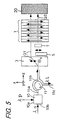
- FIG. 4 is a block diagram showing a fourth embodiment of the invention.
- the wavelength conversion apparatus includes a multiplexer 10, a polarization separation element 3, wavelength conversion elements 1 and 2, a polarization multiplexing element 4, and an optical delay element 7.
- the multiplexer 10 has an input port 10a to which pumped light (wavelength ⁇ p) is input and an input port 10b to which signal light (wavelength ⁇ s) is input.
- the multiplexer 10 multiplexes the pumped light and the signal light, and outputs the multiplexed lights along the same optical axis.
- the wavelength conversion elements 1 and 2 are made of a nonlinear optical material such as LN, LT, KN or KTP. In this embodiment, an example is shown that uses QPM elements whose polarization directions are alternately reversed at intervals of the coherence length.
- the wavelength conversion element 1 is disposed so that the polarization direction thereof is parallel to the x direction.
- the wavelength conversion element 2 is disposed so that the polarization direction thereof is parallel to the y direction.
- the polarization separation element 3 and the polarization multiplexing element 4 are made of a material such as a birefringent optical crystal cut obliquely with respect to the crystallographic axis (for example, YVO 4 cut in a direction at an angle of 45 degrees from the c axis) , and have the function of, by a beam walk-off effect, separating an incident light into the linearly polarized light in the x direction which travels along the optical axis Q1, as extraordinary light e , and the linearly polarized light in the y direction which travels along the optical axis Q2, as ordinary light o , or multiplexing the linearly polarized light in the x direction incident along the optical axis Q1 and the linearly polarized light in the y direction incident along the optical axis Q2.
- a birefringent optical crystal cut obliquely with respect to the crystallographic axis for example, YVO 4 cut in a direction at an angle of 45 degrees from
- the optical delay element 7 is made of a transparent material or the like having a predetermined optical length, and has the function of making the optical lengths of the optical axes Q1 and Q2 from the incident surface of the polarization separation element 3 to the exit surface of the polarization multiplexing device 4 coincide with each other to thereby eliminate the phase difference, in the case of pulses, the pulse delay time difference between the output lights generated along the optical axes Q1 and Q2.
- the optical delay element 7 can be omitted.
- the wavelength ⁇ s is set in the C band
- the wavelength ⁇ L is set in the L band
- the wavelength ⁇ p is set to 1.56 ⁇ m at the midpoint between the C band and the L band.
- the pumped light and the signal light are multiplexed by the multiplexer 10 and incident on the polarization separation element 3. Then, the linearly polarized lights, in the x direction, of the pumped light and the signal light are separated along the optical axis Q1 by the polarization separation element 3, are wavelength-converted to an output light polarized in the x direction by the wavelength conversion element 1 polarized in the x direction, and enter the polarization multiplexing element 4.
- the linearly polarized lights, in the y direction, of the pumped light and the signal light are separated along the optical axis Q2 by the polarization separation element 3, are wavelength-converted to an output light polarized in the y direction by the wavelength conversion element 1 polarized in the y direction, and after passing through the optical delay element 7, enter the polarization multiplexing element 4.
- the polarization multiplexing element 4 multiplexes the pumped lights, the signal lights and the output lights incident along the optical axes Q1 and Q2, and outputs the multiplexed lights along the same optical axes.
- the composite intensity of the wavelength-converted output lights is constant, so that stable wavelength conversion not depending on the polarization condition of the signal light can be realized.
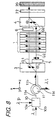
- FIG. 5 is a block diagram showing a fifth embodiment of the invention.
- the wavelength conversion apparatus includes a multiplexer 10, a light circulator 11, a polarization separation device 3, a wavelength conversion element 1, a reflecting mirror 20, a 90-degree polarization rotating element 5, and an optical delay element 7.
- the multiplexer 10 has an input port 10a to which pumped light (wavelength ⁇ p) is input and an input port 10b to which signal light (wavelength ⁇ s) is input.
- the multiplexer 10 multiplexes the pumped light and the signal light, and outputs the multiplexed lights along the same optical axis.
- the light circulator 11 outputs the light input to a port 11a to a port 11b, and outputs the light input to the port 11b to a port 11c.
- the wavelength conversion element 1 is made of a nonlinear optical material such as LN, LT, KN or KTP. In this embodiment, an example is shown that uses a QPM element whose polarization direction is alternately reversed at intervals of the coherence length.
- the wavelength conversion element 1 is disposed so that the polarization direction thereof is parallel to the x direction.
- the polarization separation element 3 is made of a material such as a birefringent optical crystal cut obliquely with respect to the crystallographic axis (for example, YVO 4 cut in a direction at an angle of 45 degrees from the c axis), and has the function of, by a beam walk-off effect, separating an incident light into the linearly polarized light in the x direction which travels along the optical axis Q1, as extraordinary light e , and the linearly polarized light in the y direction which travels along the optical axis Q2, as ordinary light o , or multiplexing the linearly polarized light in the x direction incident along the optical axis Q1 and the linearly polarized light in the y direction incident along the optical axis Q2.
- a birefringent optical crystal cut obliquely with respect to the crystallographic axis for example, YVO 4 cut in a direction at an angle of 45 degrees from the c axis
- the 90-degree polarization rotating element 5 comprises a half-wave plate or the like, and has the function of rotating the polarization direction of the incident light by 90 degrees.
- the optical delay element 7 is made of a transparent material or the like having a predetermined optical length, and has the function of making the optical lengths of the optical axes Q1 and Q2 from the incident surface of the polarization separation element 3 to the exit surface of the polarization multiplexing device 4 coincide with each other to thereby eliminate the phase difference, in the case of pulses, the pulse delay time difference between the output lights generated along the optical axes Q1 and Q2.
- the optical delay element 7 can be omitted.
- the wavelength ⁇ s is set in the C band
- the wavelength ⁇ L is set in the L band
- the wavelength ⁇ p is set to 1.56 ⁇ m at the midpoint between the C band and the L band.
- the pumped light and the signal light are multiplexed by the multiplexer 10 and incident on the polarization separation element 3 by way of the port 11a and the port 11b of the light circulator 11. Then, the linearly polarized lights, in the x direction, of the pumped light and the signal light are separated along the optical axis Q1 by the polarization separation element 3, and are wavelength-converted to an output light polarized in the x direction by the wavelength conversion element 1 polarized in the x direction.
- the linearly polarized lights, in the y direction, of the pumped light and the signal light are separated along the optical axis Q2 by the polarization separation element 3, are converted to a linearly polarized light in the x direction by the 90-degree polarization rotating element 5, and after passing through the optical delay element 7, are wavelength-converted to an output light polarized in the x direction by the wavelength conversion element 1.
- the pumped lights, the signal lights and the output lights traveling from the wavelength conversion element 1 along the optical axes Q1 and Q2 are reflected at the reflecting mirror 20, and then, again pass through the same wavelength conversion element 1 to be wavelength-converted.
- the pumped light, the signal light and the output light traveling along the optical axis Q1 enter the polarization separation element 3 as they are.
- the pumped light, the signal light and the output light traveling along the optical axis Q2 pass through the optical delay element 7, and then enter the polarization separation element 3 with the polarization directions thereof made parallel to the y direction by the 90-degree polarization rotating device 5.
- the pumped lights, the signal lights and the output lights traveling along the optical axes Q1 and Q2 are multiplexed by the polarization separation element 3.
- the output lights are extracted by way of the port 11b and the port 11c of the light circulator 11.
- the composite intensity of the wavelength-converted output lights is constant, so that stable wavelength conversion not depending on the polarization condition of the signal light can be realized.
- FIG. 6 is a block diagram showing a sixth embodiment of the invention.
- the wavelength conversion apparatus includes amultiplexer 10, a light circulator 11, apolarization separation element 3, a wavelength conversion element 1, a reflecting mirror 20, and an optical delay element 7.
- the multiplexer 10 has an input port 10a to which pumped light (wavelength ⁇ p) is input and an input port 10b to which signal light (wavelength ⁇ s) is input.
- the multiplexer 10 multiplexes the pumped light and the signal light, and outputs the multiplexed lights along the same optical axis.
- the light circulator 11 outputs the light input to a port 11a to a port 11b, and outputs the light input to the port 11b to a port 11c.
- the wavelength conversion elements 1 and 2 are made of a nonlinear optical material such as LN, LT, KN or KTP. In this embodiment, an example is shown that uses QPM elements whose polarization directions are alternately reversed at intervals of the coherence length.
- the wavelength conversion element 1 is disposed so that the polarization direction thereof is parallel to the x direction.
- the wavelength conversion element 2 is disposed so that the polarization direction thereof is parallel to the y direction (vertical to the plane of the figure and vertical to the optical axis).
- the polarization separation element 3 is made of a material such as a birefringent optical crystal cut obliquely with respect to the crystallographic axis (for example, YVO 4 cut in a direction at an angle of 45 degrees from the c axis), and has the function of, by a beam walk-off effect, separating an incident light into the linearly polarized light in the x direction which travels along the optical axis Q1, as extraordinary light e, and the linearly polarized light in the y direction which travels along the optical axis Q2, as ordinary light o, or multiplexing the linearly polarized light in the x direction incident along the optical axis Q1 and the linearlypolarized light in the y direction incident along the optical axis Q2.
- a birefringent optical crystal cut obliquely with respect to the crystallographic axis for example, YVO 4 cut in a direction at an angle of 45 degrees from the c axis
- the optical delay element 7 is made of a transparent material or the like having a predetermined optical length, and has the function of making the optical lengths of the optical axes Q1 and Q2 from the incident surface of the polarization separation element 3 to the exit surface of the polarization multiplexing device 4 coincide with each other to thereby eliminate the phase difference, in the case of pulses, the pulse delay time difference between the output lights generated along the optical axes Q1 and Q2.
- the optical delay element 7 can be omitted.
- the wavelength ⁇ s is set in the C band
- the wavelength ⁇ L is set in the L band
- the wavelength ⁇ p is set to 1.56 ⁇ m at the midpoint between the C band and the L band.
- the pumped light and the signal light are multiplexed by the multiplexer 10 and incident on the polarization separation element 3 by way of the port 11a and the port 11b of the light circulator 11. Then, the linearly polarized lights, in the x direction, of the pumped light and the signal light are separated along the optical axis Q1 by the polarization separation element 3, and are wavelength-converted to an output light polarized in the x direction by the wavelength conversion element 1 polarized in the x direction.
- the linearly polarized lights, in the y direction, of the pumped light and the signal light are separated along the optical axis Q2 by the polarization separation element 3, and after passing through the optical delay element 7, are wavelength-converted to an output light polarized in the y direction by the wavelength conversion element 2 polarized in the y direction.
- the pumped lights, the signal lights and the output lights traveling from the wavelength conversion element 1 along the optical axes Q1 and Q2 are reflected at the reflecting mirror 20, and then, again pass through the same wavelength conversion elements 1 and 2 to be wavelength-converted.
- the pumped light, the signal light and the output light traveling along the optical axis Q1 enter the polarization separation element 3 as they are.
- the pumped light, the signal light and the output light traveling along the optical axis Q2 pass through the optical delay element 7, and then enter the polarization separation element 3.
- the pumped lights, the signal lights and the output lights traveling along the optical axes Q1 and Q2 are multiplexed by the polarization separation element 3.
- the output lights are extracted by way of the port 11b and the port 11c of the light circulator 11.
- the composite intensity of the wavelength-converted output lights is constant, so that stable wavelength conversion not depending on the polarization condition of the signal light can be realized.
- FIG. 7 is a block diagram showing a seventh embodiment of the invention.
- the wavelength conversion apparatus includes amultiplexer 10, a light circulator 11, apolarization separation element 3, a wavelength conversion element 1, a polarization multiplexing element 4, a Faraday rotator 22, and a reflecting mirror 20.
- the multiplexer 10 has an input port 10a to which pumped light (wavelength ⁇ p) is input and an input port 10b to which signal light (wavelength ⁇ s) is input.
- the multiplexer 10 multiplexes the pumped light and the signal light, and outputs the multiplexed lights along the same optical axis.
- the light circulator 11 outputs the light input to a port 11a to a port 11b, and outputs the light input to the port 11b to a port 11c.
- the wavelength conversion element 1 is made of a nonlinear optical material such as LN, LT, KN or KTP. In this embodiment, an example is shown that uses a QPM element whose polarization direction is alternately reversed at intervals of the coherence length.
- the wavelength conversion element 1 is disposed so that the polarization direction thereof is parallel to the x direction.
- the polarization separation element 3 and the polarization multiplexing element 4 are made of a material such as a birefringent optical crystal cut obliquely with respect to the crystallographic axis (for example, YVO 4 cut in a direction at an angle of 45 degrees from the c axis), and have the function of, by a beam walk-off effect, separating an incident light into the linearly polarized light in the x direction which travels along the optical axis Q1, as extraordinary light e, and the linearly polarized light in the y direction which travels along the optical axis Q2, as ordinary light o, or multiplexing the linearly polarized light in the x direction incident along the optical axis Q1 and the linearly polarized light in the y direction incident along the optical axis Q2.
- a birefringent optical crystal cut obliquely with respect to the crystallographic axis for example, YVO 4 cut in a direction at an angle of 45 degrees from the c
- the Faraday rotator 22 rotates the polarization direction of light by 45 degrees about the optical axis in a predetermined direction.
- the reflecting mirror 20 reflects the incident light onto the same optical axis.
- the wavelength ⁇ s is set in the C band
- the wavelength ⁇ L is set in the L band
- the wavelength ⁇ p is set to 1.56 ⁇ m at the midpoint between the C band and the L band.
- the pumped light and the signal light are multiplexed by the multiplexer 10 and incident on the polarization separation element 3 by way of the port 11a and the port 11b of the light circulator 11. Then, the linearly polarized lights, in the x direction, of the pumped light and the signal light are separated along the optical axis Q1 by the polarization separation element 3, are wavelength-converted to an output light polarized in the x direction by the wavelength conversion element 1 polarized in the x direction, and enter the polarization multiplexing element 4.
- the linearly polarized lights, in the y direction, of the pumped light and the signal light are separated along the optical axis Q2 by the polarization separation element 3, and enter the polarization multiplexing element 4 without wavelength-converted by the wavelength conversion element 1.
- the polarization multiplexing element 4 multiplexes the pumped lights, the signal lights and the output lights incident along the optical axes Q1 and Q2, and outputs the multiplexed lights along the same optical axes.
- the pumped lights, the signal lights and the output lights pass through the Faraday rotator 22, so that the polarization directions thereof are rotated by 45 degrees.
- the lights are reflected at the reflecting mirror 20, and again pass through the Faraday rotator 22, so that the polarization directions thereof are further rotated by 45 degrees.
- the polarization directions are rotated by 90 degrees with respect to the directions before the lights are incident on the Faraday rotator 22.
- the linearly polarized lights in the x direction are separated along the optical axis Q1, are wavelength-converted to an output light polarized in the x direction by the wavelength conversion element 1 polarized in the x direction, and enter the polarization separation element 3.
- the linearly polarized lights in the y direction are separated along the optical axis Q2, and enter the polarization separation element 3 without wavelength-converted by the wavelength conversion element 1.
- the polarization separation element 3 multiplexes the pumped lights, the signal lights and the output lights incident along the optical axes Q1 and Q2, and outputs the multiplexed lights along the same optical axes.
- the wavelength-converted output lights are extracted by way of the port 11b and the port 11c of the light circulator 11.
- the composite intensity of the wavelength-converted output lights is constant, so that stable wavelength conversion not depending on the polarization condition of the signal light can be realized.
- the optical lengths through which the x-direction and the y-direction components before input pass are the same, influence of polarizationmode dispersion (PMD) can be prevented.
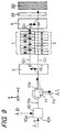
- FIG. 8 is a block diagram showing an eighth embodiment of the invention.
- the wavelength conversion apparatus includes amultiplexer 10, a light circulator 11, apolarization separation element 3, a wavelength conversion element 1, a polarization multiplexing element 4, 90-degree polarization rotating elements 5 and 6, a Faraday rotator 22, and a reflecting mirror 20.
- the multiplexer 10 has an input port 10a to which pumped light (wavelength ⁇ p) is input and an input port 10b to which signal light (wavelength ⁇ s) is input.
- the multiplexer 10 multiplexes the pumped light and the signal light, and outputs the multiplexed lights along the same optical axis.
- the light circulator 11 outputs the light input to a port 11a to a port 11b, and outputs the light input to the port 11b to a port 11c.
- the wavelength conversion element 1 is made of a nonlinear optical material such as LN, LT, KN or KTP. In this embodiment, an example is shown that uses a QPM element whose polarization direction is alternately reversed at intervals of the coherence length.
- the wavelength conversion element 1 is disposed so that the polarization direction thereof is parallel to the x direction.
- the polarization separation element 3 and the polarization multiplexing element 4 are made of a material such as a birefringent optical crystal cut obliquely with respect to the crystallographic axis (for example, YVO 4 cut in a direction at an angle of 45 degrees from the c axis), and have the function of, by a beam walk-off effect, separating an incident light into the linearly polarized light in the x direction which travels along the optical axis Q1, as extraordinary light e, and the linearly polarized light in the y direction which travels along the optical axis Q2, as ordinary light o, or multiplexing the linearly polarized light in the x direction incident along the optical axis Q1 and the linearly polarized light in the y direction incident along the optical axis Q2.
- a birefringent optical crystal cut obliquely with respect to the crystallographic axis for example, YVO 4 cut in a direction at an angle of 45 degrees from the c
- the 90-degree polarization rotating elements 5 and 6 comprise half-wave plates or the like, and have the function of rotating the polarization direction of the incident light by 90 degrees.
- the Faraday rotator 22 rotates the polarization direction of light by 45 degrees about the optical axis in a predetermined direction.
- the reflecting mirror 20 reflects the incident light onto the same optical axis.
- the wavelength ⁇ s is set in the C band
- the wavelength ⁇ L is set in the L band
- the wavelength ⁇ p is set to 1.56 ⁇ m at the midpoint between the C band and the L band.
- the pumped light and the signal light are multiplexed by the multiplexer 10 and incident on the polarization separation element 3 by way of the port 11a and the port 11b of the light circulator 11. Then, the linearly polarized lights, in the x direction, of the pumped light and the signal light are separated along the optical axis Q1 by the polarization separation element 3, are wavelength-converted to an output light polarized in the x direction by the wavelength conversion element 1 polarized in the x direction, are converted to a linearly polarized light in the y direction by the 90-degree polarization rotating element 6, and then enter the polarization multiplexing element 4.
- the linearly polarized lights, in the y direction, of the pumped light and the signal light are separated along the optical axis Q2 by the polarization separation element 3, are converted to a linearly polarized light in the x direction by the 90-degree polarization rotating element 5, are wavelength-converted to an output light polarized in the x direction by the wavelength conversion element 1, and then enter the polarization multiplexing element 4.
- the polarization multiplexing element 4 multiplexes the pumped lights, the signal lights and the output lights incident along the optical axes Q1 and Q2, and outputs the multiplexed lights along the same optical axes.
- the pumped lights, the signal lights and the output lights pass through the Faraday rotator 22, so that the polarization directions thereof are rotated by 45 degrees.
- the lights are reflected at the reflecting mirror 20, and again pass through the Faraday rotator 22, so that the polarization directions thereof are further rotated by 45 degrees .
- the polarization directions are rotated by 90 degrees with respect to the directions before the lights are incident on the Faraday rotator 22.
- the linearly polarized lights in the x direction are separated along the optical axis Q2, are wavelength-converted to an output light polarized in the x direction by the wavelength conversion element 1 polarized in the x direction, are converted to a linearly polarized light in the y direction by the 90-degree polarization rotating element 5, and enter the polarization separation element 3.
- the linearly polarized lights in the y direction are separated along the optical axis Q1, are converted to a linearly polarized light in the x direction by the 90-degree polarization rotating element 5, are wavelength-converted to an output light polarized in the x direction by the wavelength conversion element 1, and enter the polarization separation element 3.
- the polarization separation element 3 multiplexes the pumped lights, the signal lights and the output lights incident along the optical axes Q1 and Q2, and outputs the multiplexed lights along the same optical axes.
- the wavelength-converted output lights are extracted by way of the port 11b and the port 11c of the light circulator 11.
- the composite intensity of the wavelength-converted output lights is constant, so that stable wavelength conversion not depending on the polarization condition of the signal light can be realized.
- the optical lengths through which the x-direction and the y-direction components before input pass are the same, influence of polarizationmode dispersion (PMD) can be prevented.
- FIG. 9 is a block diagram showing a ninth embodiment of the invention.
- the wavelength conversion element includes a multiplexer 10, a light circulator 11, a polarization separation device 3, wavelength conversion elements 1 and 2, a polarization multiplexing element 4, a Faraday rotator 22, and a reflecting mirror 20.
- the multiplexer 10 has an input port 10a to which pumped light (wavelength ⁇ p) is input and an input port 10b to which signal light (wavelength ⁇ s) is input.
- the multiplexer 10 multiplexes the pumped light and the signal light, and outputs the multiplexed lights along the same optical axis.
- the light circulator 11 outputs the light input to a port 11a to a port 11b, and outputs the light input to the port 11b to a port 11c.
- the wavelength conversion elements 1 and 2 are made of a nonlinear optical material such as LN, LT, KN or KTP. In this embodiment, an example is shown that uses QPM elements whose polarization directions are alternately reversed at intervals of the coherence length.
- the wavelength conversion element 1 is disposed so that the polarization direction thereof is parallel to the x direction.
- the wavelength conversion element 2 is disposed so that the polarization direction thereof is parallel to the y direction.
- the polarization separation element 3 and the polarization multiplexing element 4 are made of a material such as a birefringent optical crystal cut obliquely with respect to the crystallographic axis (for example, YVO 4 cut in a direction at an angle of 45 degrees from the c axis), and have the function of, by a beam walk-off effect, separating an incident light into the linearly polarized light in the x direction which travels along the optical axis Q1, as extraordinary light e , and the linearly polarized light in the y direction which travels along the optical axis Q2, as ordinary light o , or multiplexing the linearly polarized light in the x direction incident along the optical axis Q1 and the linearly polarized light in they direction incident along the optical axis Q2.
- a birefringent optical crystal cut obliquely with respect to the crystallographic axis for example, YVO 4 cut in a direction at an angle of 45 degrees from the c
- the Faraday rotator 22 rotates the polarization direction of light by 45 degrees about the optical axis in a predetermined direction.
- the reflecting mirror 20 reflects the incident light onto the same optical axis.
- the wavelength ⁇ s is set in the C band
- the wavelength ⁇ L is set in the L band
- the wavelength ⁇ p is set to 1.56 ⁇ m at the midpoint between the C band and the L band.
- the pumped light and the signal light are multiplexed by the multiplexer 10 and incident on the polarization separation element 3 by way of the port 11a and the port 11b of the light circulator 11. Then, the linearly polarized lights, in the x direction, of the pumped light and the signal light are separated along the optical axis Q1 by the polarization separation element 3, are wavelength-converted to an output light polarized in the x direction by the wavelength conversion element 1 polarized in the x direction, and enter the polarization multiplexing element 4.
- the linearly polarized lights, in the y direction, of the pumped light and the signal light are separated along the optical axis Q2 by the polarization separation element 3, are wavelength-converted to an output light polarized in the y direction by the wavelength conversion element 2 polarized in the y direction, and enter the polarization multiplexing element 4.
- the polarization multiplexing element 4 multiplexes the pumped lights, the signal lights and the output lights incident along the optical axes Q1 and Q2, and outputs the multiplexed lights along the same optical axes.
- the pumped lights, the signal lights and the output lights pass through the Faraday rotator 22, so that the polarization directions thereof are rotated by 45 degrees.
- the lights are reflected at the reflecting mirror 20, and again pass through the Faraday rotator 22, so that the polarization directions thereof are further rotated by 45 degrees.
- the polarization directions are rotated by 90 degrees with respect to the directions before the lights are incident on the Faraday rotator 22.
- the linearly polarized lights in the x direction are separated along the optical axis Q1, are wavelength-converted to an output light polarized in the x direction by the wavelength conversion element 1 polarized in the x direction, and enter the polarization separation element 3.
- the linearly polarized lights in the y direction are separated along the optical axis Q2, are wavelength-converted to an output light polarized in the y direction by the wavelength conversion element 2, and enter the polarization separation element 3.
- the polarization separation element 3 multiplexes the pumped lights, the signal lights and the output lights incident along the optical axes Q1 and Q2, and outputs the multiplexed lights along the same optical axes.
- the wavelength-converted output lights are extracted by way of the port 11b and the port 11c of the light circulator 11.
- the composite intensity of the wavelength-converted output lights is constant, so that stable wavelength conversion not depending on the polarization condition of the signal light can be realized.
- the optical lengths through which the x-direction and the y-direction components before input pass are the same, influence of polarization mode dispersion (PMD) can be prevented.
Landscapes
- Physics & Mathematics (AREA)
- Nonlinear Science (AREA)
- General Physics & Mathematics (AREA)
- Optics & Photonics (AREA)
- Optical Modulation, Optical Deflection, Nonlinear Optics, Optical Demodulation, Optical Logic Elements (AREA)
- Optical Communication System (AREA)
Abstract
Description
Claims (12)
- A wavelength conversion apparatus comprising:a wavelength conversion element (1, 2) for carrying out wavelength conversion of a linearly polarized light component in a first direction; andpolarization rotating means (5, 6) including a reflecting element (20) for reflecting light having passed through the wavelength conversion element to return the light to the wavelength conversion element, for making a polarization direction difference of 90 degrees between a light traveling from the wavelength conversion element to the reflecting element and a light reflected at the reflecting element so as to return to the wavelength conversion element.
- The wavelength conversion apparatus of claim 1, further comprising:a wavelength selection reflecting element (21), disposed between the wavelength conversion element and the polarization rotating means, for selectively reflecting a pumped light.
- A wavelength conversion apparatus comprising:a polarization separation element (3) made of a birefringent material, for separating, by beam walk-off, a light to be wavelength-converted into two linearly polarized light components perpendicular to each other so as to travel along two different optical axes;a wavelength conversion element (1, 2) for performing wavelength conversion in accordance with the linearly polarized light components traveling along the two optical axes; anda polarization multiplexing element (4) for multiplexing two lights having passed through the wavelength conversion element.
- A wavelength conversion apparatus comprising:a polarization separation element (3) for separating an incident light into a linearly polarized light in a first direction and a linearly polarized light in a second direction perpendicular to the first direction so that the linearly polarized light in the first direction travels along a first optical axis and the linearly polarized light in the second direction travels along a second optical axis;a first 90-degree polarization rotating element (5) for rotating by 90 degrees a polarization direction of a light traveling from the polarization separation element along the second optical axis;a wavelength conversion element (1, 2) for wavelength-converting linearly polarized light components in the first direction with respect to a light traveling from the polarization separation element along the first optical axis and a light traveling from the first 90-degree polarization rotating element along the second optical axis;a second 90-degree polarization rotating element (6) for rotating by 90 degrees a polarization direction of a light traveling from the wavelength conversion element along the first optical axis; anda polarization multiplexing element (4) for multiplexing a light traveling from the second 90-degree polarization rotating element along the first optical axis and a light traveling from the wavelength conversion element along the second optical axis .
- A wavelength conversion apparatus comprising:a polarization separation element (3) for separating an incident light into a linearly polarized light in a first direction and a linearly polarized light in a second direction perpendicular to the first direction so that the linearly polarized light in the first direction travels along a first optical axis and the linearly polarized light in the second direction travels along a second optical axis;a first wavelength conversion element (1) for wavelength-converting a linearly polarized light component in the first direction, with respect to the light traveling from the polarization separation element along the first optical axis;a second wavelength conversion element (2) for wavelength-converting a linearly polarized light component in the second direction, with respect to a light traveling from the polarization separation element along the second optical axis; anda polarization multiplexing element (4) for multiplexing a light having passed through the first wavelength conversion element and a light having passed through the second wavelength conversion element.
- A wavelength conversion apparatus comprising:a polarization separation element (3) for separating an incident light into a linearly polarized light in a first direction and a linearly polarized light in a second direction perpendicular to the first direction so that the linearly polarized light in the first direction travels along a first optical axis and the linearly polarized light in the second direction travels along a second optical axis;a 90-degree polarization rotating element (5) for rotating by 90 degrees a polarization direction of a light traveling from the polarization separation element along the second optical axis;a wavelength conversion element (1, 2) for wavelength-converting linearly polarized light components in the first direction, with respect to the light traveling from the polarization separation element along the first optical axis and the light traveling from the 90-degree polarization rotating element along the second optical axis; anda reflecting element (20) for reflecting lights traveling from the wavelength conversion element along the first optical axis and the second optical axis so that the light along the first optical axis passes through the wavelength conversion element, the light along the second optical axis passes through the wavelength conversion element and the 90-degree polarization rotating element in this order and these light are multiplexed by the polarization separation element.
- A wavelength conversion apparatus comprising:a polarization separation element (3) for separating an incident light into a linearly polarized light in a first direction and a linearly polarized light in a second direction perpendicular to the first direction so that the linearly polarized light in the first direction travels along a first optical axis and the linearly polarized light in the second direction travels along a second optical axis;a first wavelength conversion element (1) for wavelength-converting a linearly polarized light component in the first direction, with respect to the light traveling from the polarization separation element along the first optical axis;a second wavelength conversion element (2) for wavelength-converting a linearly polarized light component in the second direction, with respect to the light traveling from the polarization separation element along the second optical axis; anda reflecting element (20) for reflecting a light traveling from the first wavelength conversion element along the first optical axis and a light traveling from the second wavelength conversion element along the second optical axis so that a light having passed through the first wavelength conversion element and a light having passed through the second wave length conversion element are multiplexed by the polarization separation element.
- A wavelength conversion apparatus comprising:a polarization separation element (3) for separating an incident light into a linearly polarized light in a first direction and a linearly polarized light in a second direction perpendicular to the first direction so that the linearly polarized light in the first direction travels along a first optical axis and the linearly polarized light in the second direction travels along a second optical axis;a wavelength conversion element (1, 2) for wavelength-converting a linearly polarized light component in the first direction, with respect to the light traveling from the polarization separation element along the first optical axis;a polarization multiplexing element (4) for multiplexing a light traveling from the wavelength conversion element along the first optical axis and a light traveling from the polarization separation element along the second optical axis; andpolarization rotating means (20, 22) including a reflecting element for reflecting a light having passed through the polarization multiplexing element to return the light to the wavelength conversion element, for making a polarization direction difference of 90 degrees between a light traveling from the wavelength conversion element to the reflecting element and a light reflected at the reflecting element so as to return to the wavelength conversion element.
- A wavelength conversion apparatus comprising:a polarization separation element (3) for separating an incident light into a linearly polarized light in a first direction and a linearly polarized light in a second direction perpendicular to the first direction so that the linearly polarized light in the first direction travels along a first optical axis and the linearly polarized light in the second direction travels along a second optical axis;a first 90-degree polarization rotating element (5) for rotating by 90 degrees a polarization direction of a light traveling from the polarization separation element along the second optical axis;a wavelength conversion element (1, 2) for wavelength-converting linearly polarized light components in the first direction, with respect to a light traveling from the polarization separation element along the first optical axis and a light traveling from the first 90-degree polarization rotating element along the second optical axis;a second 90-degree polarization rotating element (6) for rotating by 90 degrees a polarization direction of a light traveling from the wavelength conversion element along the first optical axis;a polarization multiplexing element (4) for multiplexing a light traveling from the second 90-degree polarization rotating element along the first optical axis and a light traveling from the wavelength conversion element along the second optical axis; andpolarization rotating means (20, 22) including a reflecting element for reflecting a light having passed through the polarization multiplexing element to return the light to the wavelength conversion element, for making a polarization direction difference of 90 degrees between a light traveling from the wavelength conversion element to the reflecting element and a light reflected at the reflecting element so as to return to the wavelength conversion element.
- A wavelength conversion apparatus comprising:a polarization separation element (3) for separating an incident light into a linearly polarized light in a first direction and a linearly polarized light in a second direction perpendicular to the first direction so that the linearly polarized light in the first direction travels along a first optical axis and the linearly polarized light in the second direction travels along a second optical axis;a first wavelength conversion element (1) for wavelength-converting a linearly polarized light component in the first direction, with respect to a light traveling from the polarization separation element along the first optical axis;a second wavelength conversion element (2) for wavelength-converting a linearly polarized light component in the second direction, with respect to a light traveling from the polarization separation element along the second optical axis;a polarization multiplexing element (4) for multiplexing a light traveling from the first wavelength conversion element along the first optical axis and a light traveling from the second wavelength conversion element along the second optical axis; andpolarization rotating means (20, 22) including a reflecting element for reflecting a light having passed through the polarization multiplexing element to return the light to the wavelength conversion element, for making a polarization direction difference of 90 degrees between a light traveling from the wavelength conversion element to the reflecting element and a light reflected at the reflecting element so as to return to the wavelength conversion element.
- The wavelength conversion apparatus of any one of claims 1, 2, 8, 9 and 10, wherein the polarization rotating means comprises a 45-degree rotating element (22) for rotating a polarization direction of light by 45 degrees and the reflecting element (20) for reflecting a light having passed through the 45-degree polarization rotating element to return the light to the 45-degree polarization rotating element, and the 45-degree rotating element is disposed between the wavelength conversion element and the reflecting element.
- The wavelength conversion apparatus of any one of claims 1, 2, 8, 9 and 10, wherein the polarization rotating means comprises a λ/4 plate disposed between the reflecting element and the wavelength conversion element, and the reflecting element.
Applications Claiming Priority (2)
| Application Number | Priority Date | Filing Date | Title |
|---|---|---|---|
| JP2000275496 | 2000-09-11 | ||
| JP2000275496 | 2000-09-11 |
Publications (2)
| Publication Number | Publication Date |
|---|---|
| EP1186942A2 true EP1186942A2 (en) | 2002-03-13 |
| EP1186942A3 EP1186942A3 (en) | 2002-11-20 |
Family
ID=18761108
Family Applications (1)
| Application Number | Title | Priority Date | Filing Date |
|---|---|---|---|
| EP01121608A Withdrawn EP1186942A3 (en) | 2000-09-11 | 2001-09-11 | Wavelength conversion apparatus |
Country Status (3)
| Country | Link |
|---|---|
| US (1) | US6744554B2 (en) |
| EP (1) | EP1186942A3 (en) |
| CN (1) | CN1343906A (en) |
Cited By (3)
| Publication number | Priority date | Publication date | Assignee | Title |
|---|---|---|---|---|
| EP1467242A1 (en) * | 2003-04-10 | 2004-10-13 | Agilent Technologies, Inc. | Double-pass polarization-independent mixer and method using single nonlinear mixer media and off-axis focusing |
| EP1363420A3 (en) * | 2002-05-17 | 2006-04-19 | Nippon Telegraph and Telephone Corporation | Optical modulation/multiplexing circuit |
| WO2008119423A1 (en) * | 2007-03-30 | 2008-10-09 | Oerlikon Trading Ag, Trübbach | Laser module for projectors |
Families Citing this family (8)
| Publication number | Priority date | Publication date | Assignee | Title |
|---|---|---|---|---|
| JP4359035B2 (en) * | 2002-11-21 | 2009-11-04 | 富士通株式会社 | Optical repeater |
| US20050244159A1 (en) * | 2004-04-30 | 2005-11-03 | Aref Chowdhury | Optical wavelength-conversion |
| EP1744476A1 (en) * | 2005-07-12 | 2007-01-17 | Alcatel | Transmission method and processing unit for a modulated optical signal |
| JP5076099B2 (en) * | 2006-03-09 | 2012-11-21 | 並木精密宝石株式会社 | Reflective optical circulator |
| KR100794968B1 (en) | 2006-05-19 | 2008-01-16 | 충남대학교산학협력단 | Wavelength Converter Using Semiconductor Optical Amplifier |
| CN102262303B (en) * | 2010-05-27 | 2013-01-16 | 华为技术有限公司 | Optical interleaving filtering device for realizing polarization wave combination function and method thereof |
| US8922873B2 (en) * | 2011-02-11 | 2014-12-30 | University Of Dayton | Compact narrow bandwidth tunable source |
| CN103760732B (en) * | 2014-01-14 | 2017-01-04 | 中国电子科技集团公司第三十四研究所 | A cascaded sum frequency and difference frequency all-optical wavelength converter and conversion method |
Family Cites Families (6)
| Publication number | Priority date | Publication date | Assignee | Title |
|---|---|---|---|---|
| US4684828A (en) * | 1985-03-12 | 1987-08-04 | Zygo Corporation | Apparatus to transform a single frequency, linearly polarized laser beam into a beam with two, orthogonally polarized frequencies |
| US5400164A (en) * | 1993-09-10 | 1995-03-21 | At&T Corp. | Polarization-insensitive optical four-photon mixer |
| JPH10213826A (en) | 1997-01-30 | 1998-08-11 | Oki Electric Ind Co Ltd | Wavelength converter |
| JP4110619B2 (en) | 1998-06-18 | 2008-07-02 | 沖電気工業株式会社 | Wavelength converter |
| JP3907861B2 (en) * | 1999-02-17 | 2007-04-18 | 富士通株式会社 | Method and apparatus for wavelength conversion and system including the apparatus |
| EP1139160A3 (en) * | 2000-03-21 | 2004-01-02 | Nippon Telegraph and Telephone Corporation | Optical parametric circuit |
-
2001
- 2001-09-11 CN CN01137643A patent/CN1343906A/en active Pending
- 2001-09-11 US US09/950,558 patent/US6744554B2/en not_active Expired - Fee Related
- 2001-09-11 EP EP01121608A patent/EP1186942A3/en not_active Withdrawn
Cited By (3)
| Publication number | Priority date | Publication date | Assignee | Title |
|---|---|---|---|---|
| EP1363420A3 (en) * | 2002-05-17 | 2006-04-19 | Nippon Telegraph and Telephone Corporation | Optical modulation/multiplexing circuit |
| EP1467242A1 (en) * | 2003-04-10 | 2004-10-13 | Agilent Technologies, Inc. | Double-pass polarization-independent mixer and method using single nonlinear mixer media and off-axis focusing |
| WO2008119423A1 (en) * | 2007-03-30 | 2008-10-09 | Oerlikon Trading Ag, Trübbach | Laser module for projectors |
Also Published As
| Publication number | Publication date |
|---|---|
| US20020063945A1 (en) | 2002-05-30 |
| US6744554B2 (en) | 2004-06-01 |
| CN1343906A (en) | 2002-04-10 |
| EP1186942A3 (en) | 2002-11-20 |
Similar Documents
| Publication | Publication Date | Title |
|---|---|---|
| US8149501B2 (en) | Quantum entangled photon pair generating device | |
| Smith et al. | Integrated-optic acoustically-tunable filters for WDM networks | |
| US5002349A (en) | Integrated acousto-optic filters and switches | |
| EP0828178B1 (en) | Wavelength conversion apparatus with improved efficiency, easy adjustability, and polarization insensitivity | |
| USRE37044E1 (en) | Tunable add/drop optical filter | |
| US8242435B2 (en) | Quantum entangled photon pair generating device | |
| US6867903B2 (en) | Optical parametric circuit | |
| US20130258453A1 (en) | Quantum entangled photon pair generator | |
| EP1186942A2 (en) | Wavelength conversion apparatus | |
| US20250110380A1 (en) | Versatile Method for Two-Photon Entanglement Generation | |
| US7009759B2 (en) | Multiple channel optical frequency mixers for all-optical signal processing | |
| Chou et al. | Optical signal processing and switching with second-order nonlinearities in waveguides | |
| US6661577B1 (en) | Wavelength-selective laser beam splitter | |
| JP3272250B2 (en) | Wavelength converter | |
| JP2014067060A (en) | Quantum entangled photon pair generator | |
| Smith et al. | Surface-acoustic-wave directional coupler for apodization of integrated acoustooptic filters | |
| JP2002156669A (en) | Apparatus for converting wavelength | |
| Hua et al. | A bright polarization-entangled photon pair source based on silicon photonics integration | |
| JP2002090786A (en) | Wavelength conversion element | |
| JPH103066A (en) | Optical modulator and wavelength add / drop module | |
| JP3470849B2 (en) | Optically driven wavelength converter | |
| JP2004093583A (en) | Wavelength conversion circuit and wavelength conversion method | |
| JPH05289124A (en) | Non-depending on polarized wave-type pulse separating circuit | |
| JP3287158B2 (en) | Nonlinear optical device | |
| JP2000010130A (en) | Wavelength converter |
Legal Events
| Date | Code | Title | Description |
|---|---|---|---|
| PUAI | Public reference made under article 153(3) epc to a published international application that has entered the european phase |
Free format text: ORIGINAL CODE: 0009012 |
|
| AK | Designated contracting states |
Kind code of ref document: A2 Designated state(s): AT BE CH CY DE DK ES FI FR GB GR IE IT LI LU MC NL PT SE TR |
|
| AX | Request for extension of the european patent |
Free format text: AL;LT;LV;MK;RO;SI |
|
| PUAL | Search report despatched |
Free format text: ORIGINAL CODE: 0009013 |
|
| AK | Designated contracting states |
Kind code of ref document: A3 Designated state(s): AT BE CH CY DE DK ES FI FR GB GR IE IT LI LU MC NL PT SE TR |
|
| AX | Request for extension of the european patent |
Free format text: AL;LT;LV;MK;RO;SI |
|
| 17P | Request for examination filed |
Effective date: 20030520 |
|
| AKX | Designation fees paid |
Designated state(s): DE FR GB IT |
|
| 17Q | First examination report despatched |
Effective date: 20030703 |
|
| RAP1 | Party data changed (applicant data changed or rights of an application transferred) |
Owner name: MITSUI CHEMICALS, INC. |
|
| STAA | Information on the status of an ep patent application or granted ep patent |
Free format text: STATUS: THE APPLICATION IS DEEMED TO BE WITHDRAWN |
|
| 18D | Application deemed to be withdrawn |
Effective date: 20060401 |