EP1186922A2 - Optical adapter - Google Patents
Optical adapter Download PDFInfo
- Publication number
- EP1186922A2 EP1186922A2 EP01121294A EP01121294A EP1186922A2 EP 1186922 A2 EP1186922 A2 EP 1186922A2 EP 01121294 A EP01121294 A EP 01121294A EP 01121294 A EP01121294 A EP 01121294A EP 1186922 A2 EP1186922 A2 EP 1186922A2
- Authority
- EP
- European Patent Office
- Prior art keywords
- conductive
- panel
- adapter
- optical
- optical adapter
- Prior art date
- Legal status (The legal status is an assumption and is not a legal conclusion. Google has not performed a legal analysis and makes no representation as to the accuracy of the status listed.)
- Withdrawn
Links
Images



Classifications
-
- G—PHYSICS
- G02—OPTICS
- G02B—OPTICAL ELEMENTS, SYSTEMS OR APPARATUS
- G02B6/00—Light guides; Structural details of arrangements comprising light guides and other optical elements, e.g. couplings
- G02B6/24—Coupling light guides
- G02B6/36—Mechanical coupling means
- G02B6/38—Mechanical coupling means having fibre to fibre mating means
- G02B6/3807—Dismountable connectors, i.e. comprising plugs
- G02B6/3897—Connectors fixed to housings, casing, frames or circuit boards
-
- G—PHYSICS
- G02—OPTICS
- G02B—OPTICAL ELEMENTS, SYSTEMS OR APPARATUS
- G02B6/00—Light guides; Structural details of arrangements comprising light guides and other optical elements, e.g. couplings
- G02B6/24—Coupling light guides
- G02B6/36—Mechanical coupling means
- G02B6/38—Mechanical coupling means having fibre to fibre mating means
- G02B6/3807—Dismountable connectors, i.e. comprising plugs
- G02B6/381—Dismountable connectors, i.e. comprising plugs of the ferrule type, e.g. fibre ends embedded in ferrules, connecting a pair of fibres
- G02B6/3825—Dismountable connectors, i.e. comprising plugs of the ferrule type, e.g. fibre ends embedded in ferrules, connecting a pair of fibres with an intermediate part, e.g. adapter, receptacle, linking two plugs
-
- G—PHYSICS
- G02—OPTICS
- G02B—OPTICAL ELEMENTS, SYSTEMS OR APPARATUS
- G02B6/00—Light guides; Structural details of arrangements comprising light guides and other optical elements, e.g. couplings
- G02B6/24—Coupling light guides
- G02B6/36—Mechanical coupling means
- G02B6/38—Mechanical coupling means having fibre to fibre mating means
- G02B6/3807—Dismountable connectors, i.e. comprising plugs
- G02B6/3873—Connectors using guide surfaces for aligning ferrule ends, e.g. tubes, sleeves, V-grooves, rods, pins, balls
- G02B6/3874—Connectors using guide surfaces for aligning ferrule ends, e.g. tubes, sleeves, V-grooves, rods, pins, balls using tubes, sleeves to align ferrules
- G02B6/3878—Connectors using guide surfaces for aligning ferrule ends, e.g. tubes, sleeves, V-grooves, rods, pins, balls using tubes, sleeves to align ferrules comprising a plurality of ferrules, branching and break-out means
-
- G—PHYSICS
- G02—OPTICS
- G02B—OPTICAL ELEMENTS, SYSTEMS OR APPARATUS
- G02B6/00—Light guides; Structural details of arrangements comprising light guides and other optical elements, e.g. couplings
- G02B6/24—Coupling light guides
- G02B6/36—Mechanical coupling means
- G02B6/38—Mechanical coupling means having fibre to fibre mating means
- G02B6/3807—Dismountable connectors, i.e. comprising plugs
- G02B6/389—Dismountable connectors, i.e. comprising plugs characterised by the method of fastening connecting plugs and sockets, e.g. screw- or nut-lock, snap-in, bayonet type
- G02B6/3893—Push-pull type, e.g. snap-in, push-on
Definitions
- the present invention relates to an adapter of an optical connector for connecting optical cables.
- An optical connector consists of a plurality of detachable plugs connected to optical cables and an adapter for retaining in alignment the detachable plugs.
- Japanese patent application Kokai No. 10-39170 discloses an optical connector with an anti-leak device.
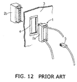
- an adapter 1 comprises conductive housings 2a and 2b to be connected to the ground face 4 of a panel 3 via a ground spring (not shown).
- a conductive plug 5 is plugged into the adapter 1 so that the conductive plug 5 and the conductive housings 2a and 2b are electrically connected to the ground face 4, preventing leak or entrance of electromagnetic waves.
- an object of the invention to provide an optical adapter capable of receiving a plurality of plugs with no or little leak or entrance of electromagnetic waves.
- An optical connector consists of a plurality of detachable plugs connected to optical cables and an optical adapter to which the detachable plugs are connected.
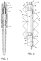
- a two-prong plug 11 comprises a pair of ferrules 12 each receiving a core wire (not shown) of an optical cable, a pair of spring 13 for forwardly biasing the ferrules 2, a pair of housings 14 each accommodating the ferrule 12 and the spring 13 and having a pair of engaging members 15 on opposite sides.
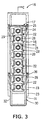
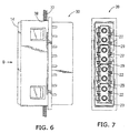
- an adapter 16 comprises a die-cast housing 17 of a conductive material, a plurality of insulator bodies 18 press-fitted in the housing 17, a plurality of split sleeve receiving caps 19 of an insulative material, and a plurality of cylindrical sleeves 20 of a metallic material.
- a plurality of partition walls 21 are provided in the housing 17 to define a plurality of plugging cavities 22 in a stepped fashion for receiving the detachable plugs 11. It is preferred that the partition walls 21 are die-cast from a conductive material integrally with the housing 17.
- a plurality of intermediate walls 29 are provided in the middle of the plugging cavities 22 in a direction perpendicular to the partition walls 21.
- the intermediate walls 29 are molded integrally with the housing 17.
- a plurality of flange portions 23 extend on the outside of the housing 17 at a constant inside angle, such as 45 degrees, with respect to the plugging direction.
- a plurality of engaging holes 42 are provided near the flange portions 23.
- At least one end of the housing 17 is folded back to provide a folded section 40, which covers the end portion 41 of the insulation body 18.
- Each plug lock 24 is made in the form of a cantilevered beam that extends in the plugging direction and has an engaging projection 25 extending inwardly from the free end.
- a plurality of wedge-shaped raised portions 43 are provided in the middle of the outside of the insulation body 18 for engagement with the engaging holes 42 to cooperate with the end portion 41 for preventing the insulation body 18 from falling from the housing 17.
- a pair of cylindrical split sleeve receiving sections 26 are provided in the plugging cavities 22 through the intermediate wall 29.
- a separation stop 27 raised inwardly from the front end of the split sleeve receiving sections 26.
- the sleeve receiving caps 19 are providing so as to correspond to the split sleeve receiving sections 26.
- a separation stop 28 is provided on the front end of the split sleeve receiving caps 19.
- a panel attaching member 30 of a conductive material is provided on the outside of the housings 17 for electrical conduction.
- a pair of panel bearing tabs 33 are provided on each side 31 and 32 of the panel attaching member 30 so as to extend along the inside of the flange sections 23, and the front end 34 of the cantilevered beam 33 is bent away from the flange section.
- An adapter lock 35 is made as a cantilevered beam near each front end 34 of the panel bearing tabs 33 such that its front end 36 is bent outwardly so as to face the front end 34 of the panel bearing tab 33.
- the adapter locks 35 are flexed inwardly by the periphery of the opening 38.
- the adapter locks 35 pass through the opening 38, they return to the original conditions to hold the periphery of the opening 38 between the front ends 34 and 36 of the panel bearing tabs 33 and the adapter locks 35.
- the spring forces of the panel bearing Labs 33 hold the panel 37 in place, with the front ends 34 being in contact with the ground face (not shown) of the panel 37 to make conductive between the panel attaching member 30 and the panel 37.
- the plugging cavities 22 are tilted by 45 degrees relative to the flange section 23 so that the adapter 16 is secured to the panel 37 under the 45-degree tilted condition.
- the plug locks 24 flex outwardly and then return to the original conditions, engaging the engaging portions 25 with the plug-side engaging portions 15.
- the housings 17 are conductive with the ground face of the panel 37 via the panel attaching members 30 so that it is possible to prevent leak or entrance of electromagnetic waves.
- the partition walls 21 provided between the plugging cavities 22 cut off transfer of electromagnetic waves between the plugging cavities 22. As shown in Figs. 9-11, the intermediate walls 29 reduce the opening area within the plugging cavities 22 so that it is possible to prevent leak and entrance of electromagnetic waves.
- an adapter 39 is attached to the panel 37 in a normal condition in contrast to the adapter 16 that is attached in a stepwise tilted condition.
- the intermediate walls 29 may be made separately from the housings 17 such that the shield plate enter the plugging cavities 22 so as to make contact with the housings 17 and partition walls 21.
- the adapter is directly attached to the panel 37 with fasteners, such as screws, thus eliminating the panel attaching members 30.
- the plugging cavities 22 may be made so as to receive single-prong plugs instead of the two-prong plugs 11.
- the partition walls are provided in the plugging cavities and the intermediate walls reduce the opening area in the plugging cavities so that leak or entrance of electromagnetic waves is minimized.
Landscapes
- Physics & Mathematics (AREA)
- General Physics & Mathematics (AREA)
- Optics & Photonics (AREA)
- Mechanical Coupling Of Light Guides (AREA)
- Connector Housings Or Holding Contact Members (AREA)
Abstract
Description
Claims (4)
- An optical adapter to be attached to a panel, comprising:a conductive housing having a plurality of plugging cavities for receiving a plurality of detachable plugs to which optical cables are connected; anda plurality of conductive partition walls provided between said plugging cavities.
- An optical adapter to be attached to a panel, comprising:a conductive housing having a plurality of plugging cavities for receiving a plurality of detachable plugs to which optical cables are connected;a plurality of conductive intermediate walls for dividing said plugging cavities such that said detachable plugs are connected through said intermediate walls.
- The optical adapter according to claim 1, which further comprises a conductive attaching member for attaching said conductive housing to said panel for electric conduction.
- The optical adapter according to claim 2, which further comprises a conductive attaching member for attaching said conductive housing to said panel for electric conduction.
Applications Claiming Priority (2)
| Application Number | Priority Date | Filing Date | Title |
|---|---|---|---|
| JP2000269929A JP3769178B2 (en) | 2000-09-06 | 2000-09-06 | Optical adapter |
| JP2000269929 | 2000-09-06 |
Publications (2)
| Publication Number | Publication Date |
|---|---|
| EP1186922A2 true EP1186922A2 (en) | 2002-03-13 |
| EP1186922A3 EP1186922A3 (en) | 2004-10-27 |
Family
ID=18756458
Family Applications (1)
| Application Number | Title | Priority Date | Filing Date |
|---|---|---|---|
| EP01121294A Withdrawn EP1186922A3 (en) | 2000-09-06 | 2001-09-05 | Optical adapter |
Country Status (3)
| Country | Link |
|---|---|
| US (1) | US6575639B2 (en) |
| EP (1) | EP1186922A3 (en) |
| JP (1) | JP3769178B2 (en) |
Cited By (1)
| Publication number | Priority date | Publication date | Assignee | Title |
|---|---|---|---|---|
| CN103048741A (en) * | 2011-10-17 | 2013-04-17 | 普泰光电股份有限公司 | Optical fiber connector and optical fiber adapter with dustproof function |
Families Citing this family (4)
| Publication number | Priority date | Publication date | Assignee | Title |
|---|---|---|---|---|
| WO2003076973A2 (en) * | 2001-10-23 | 2003-09-18 | Tyco Electronics Corporation | Single piece adapter |
| AUPS120702A0 (en) | 2002-03-18 | 2002-04-18 | Kingfisher International Pty. Ltd. | An optical fibre connector system |
| MXPA05013601A (en) * | 2003-06-25 | 2006-03-09 | Schering Corp | Metabolites of tricyclic amides useful for inhibition of g-protein function and methods of treatment of proliferative diseases. |
| JP2007183315A (en) | 2006-01-04 | 2007-07-19 | Fuji Xerox Co Ltd | Optical module |
Family Cites Families (13)
| Publication number | Priority date | Publication date | Assignee | Title |
|---|---|---|---|---|
| FR2605749B1 (en) * | 1986-10-22 | 1989-06-02 | Telemecanique Electrique | DEVICE FOR PROTECTING A FIBER OPTIC CONNECTOR AGAINST ELECTROMAGNETIC DISTURBANCES AND ELECTROSTATIC DISCHARGES |
| US5537501A (en) * | 1989-11-24 | 1996-07-16 | Nippon Telegraph And Telephone Corporation | Optical connector |
| GB9307488D0 (en) * | 1993-04-08 | 1993-06-02 | Amp Holland | Optical fibre connector latching mechanism |
| US5879173A (en) * | 1995-01-13 | 1999-03-09 | Methode Electronics, Inc. | Removable transceiver module and receptacle |
| US5937121A (en) * | 1997-01-03 | 1999-08-10 | The Siemon Company | Adapters for coupling optical fiber |
| US5966487A (en) * | 1997-05-27 | 1999-10-12 | Methode Electronics, Inc. | External pluggable high frequency data communication module |
| US6062738A (en) * | 1997-06-13 | 2000-05-16 | International Business Machines Corporation | Data communications apparatus having improved shielding structure |
| US5960136A (en) * | 1997-12-08 | 1999-09-28 | Hewlett-Packard Company | Shielded fiber optic connector |
| US6085006A (en) * | 1997-09-12 | 2000-07-04 | International Business Machines Corporation | Optical fiber link module with internal electromagnetic shield |
| US6027252A (en) * | 1997-12-19 | 2000-02-22 | The Whitaker Corporation | Simplified fiber optic receptacle |
| US6193420B1 (en) * | 1999-08-13 | 2001-02-27 | Lucent Technologies Inc. | Shielded optical fiber adaptor |
| US6419399B1 (en) * | 1999-12-01 | 2002-07-16 | 3M Innovative Properties Company | Optical fiber connector system |
| US6364534B1 (en) * | 2000-02-29 | 2002-04-02 | Lucent Technologies, Inc. | Panel mounting assembly for optical fiber connectors |
-
2000
- 2000-09-06 JP JP2000269929A patent/JP3769178B2/en not_active Expired - Fee Related
-
2001
- 2001-09-05 EP EP01121294A patent/EP1186922A3/en not_active Withdrawn
- 2001-09-05 US US09/945,631 patent/US6575639B2/en not_active Expired - Fee Related
Cited By (1)
| Publication number | Priority date | Publication date | Assignee | Title |
|---|---|---|---|---|
| CN103048741A (en) * | 2011-10-17 | 2013-04-17 | 普泰光电股份有限公司 | Optical fiber connector and optical fiber adapter with dustproof function |
Also Published As
| Publication number | Publication date |
|---|---|
| EP1186922A3 (en) | 2004-10-27 |
| JP2002082255A (en) | 2002-03-22 |
| US6575639B2 (en) | 2003-06-10 |
| JP3769178B2 (en) | 2006-04-19 |
| US20020031309A1 (en) | 2002-03-14 |
Similar Documents
| Publication | Publication Date | Title |
|---|---|---|
| EP0117022B1 (en) | Fiber optic connector assembly | |
| JP2561885B2 (en) | Modular electrical connector | |
| EP0468671B1 (en) | Fiber optic interconnect for wall outlet | |
| EP3616269B1 (en) | Connectors for a single twisted pair of conductors | |
| US6116945A (en) | Microphone connector assembly | |
| CN102067388B (en) | Electrical connector with a compliant cable strain relief element | |
| USRE39380E1 (en) | Electrical connector with protection for electrical contacts | |
| US5328382A (en) | Electrical connector with external seal and internal terminal retaining means | |
| US5855493A (en) | Electrical connector strain relief with shield ground for multiple cables | |
| US8172579B2 (en) | Electrical connector having dust-proof shutter driven by magnetic force | |
| EP0928046A1 (en) | Shielded electrical connector assembly | |
| US6890200B1 (en) | Floatable panel mount cable assembly | |
| JP4729307B2 (en) | Circuit board connector having an integral dielectric cover | |
| US6296518B1 (en) | Stacked electrical connector assembly | |
| US6741783B2 (en) | Optical cable adapter or connector | |
| US7070457B2 (en) | Telecommunications connector | |
| US5092794A (en) | Shielded electrical connector | |
| JPH0328789B2 (en) | ||
| AU2007349106B2 (en) | Electric connector with a dust cover | |
| US4883433A (en) | Electrical connector for data distribution panel | |
| CN1076810A (en) | Shielded data connector | |
| WO2004010545A1 (en) | Telecommunications connector adapted for bi-directional insertion | |
| US6575639B2 (en) | Optical adapter | |
| JPH04264377A (en) | Low-current plug socket for preliminary wiring of building | |
| KR20060065682A (en) | Triaxial bulkhead connector |
Legal Events
| Date | Code | Title | Description |
|---|---|---|---|
| PUAI | Public reference made under article 153(3) epc to a published international application that has entered the european phase |
Free format text: ORIGINAL CODE: 0009012 |
|
| AK | Designated contracting states |
Kind code of ref document: A2 Designated state(s): AT BE CH CY DE DK ES FI FR GB GR IE IT LI LU MC NL PT SE TR |
|
| AX | Request for extension of the european patent |
Free format text: AL;LT;LV;MK;RO;SI |
|
| PUAL | Search report despatched |
Free format text: ORIGINAL CODE: 0009013 |
|
| AK | Designated contracting states |
Kind code of ref document: A3 Designated state(s): AT BE CH CY DE DK ES FI FR GB GR IE IT LI LU MC NL PT SE TR |
|
| AX | Request for extension of the european patent |
Extension state: AL LT LV MK RO SI |
|
| 17P | Request for examination filed |
Effective date: 20050118 |
|
| 17Q | First examination report despatched |
Effective date: 20050425 |
|
| AKX | Designation fees paid |
Designated state(s): DE FR GB IT |
|
| STAA | Information on the status of an ep patent application or granted ep patent |
Free format text: STATUS: THE APPLICATION IS DEEMED TO BE WITHDRAWN |
|
| 18D | Application deemed to be withdrawn |
Effective date: 20051108 |