EP1186915A2 - Optical filter which counteracts a tendancy to shift optical wavelengh with change in temperature - Google Patents
Optical filter which counteracts a tendancy to shift optical wavelengh with change in temperature Download PDFInfo
- Publication number
- EP1186915A2 EP1186915A2 EP01306962A EP01306962A EP1186915A2 EP 1186915 A2 EP1186915 A2 EP 1186915A2 EP 01306962 A EP01306962 A EP 01306962A EP 01306962 A EP01306962 A EP 01306962A EP 1186915 A2 EP1186915 A2 EP 1186915A2
- Authority
- EP
- European Patent Office
- Prior art keywords
- filter layer
- filter
- light
- ring
- counteracting
- Prior art date
- Legal status (The legal status is an assumption and is not a legal conclusion. Google has not performed a legal analysis and makes no representation as to the accuracy of the status listed.)
- Granted
Links
- 230000003287 optical effect Effects 0.000 title claims description 28
- 230000005540 biological transmission Effects 0.000 claims abstract description 24
- 239000000463 material Substances 0.000 claims abstract description 24
- 238000010438 heat treatment Methods 0.000 claims abstract description 12
- 239000013307 optical fiber Substances 0.000 claims description 26
- 239000000758 substrate Substances 0.000 claims description 12
- 239000002184 metal Substances 0.000 claims description 9
- 229940085805 fiberall Drugs 0.000 claims 1
- 239000011521 glass Substances 0.000 description 7
- 239000004593 Epoxy Substances 0.000 description 2
- 230000000694 effects Effects 0.000 description 2
- 238000010276 construction Methods 0.000 description 1
- 230000008602 contraction Effects 0.000 description 1
- 230000001419 dependent effect Effects 0.000 description 1
- 230000007613 environmental effect Effects 0.000 description 1
- 238000001914 filtration Methods 0.000 description 1
- 238000000034 method Methods 0.000 description 1
- 238000012986 modification Methods 0.000 description 1
- 230000004048 modification Effects 0.000 description 1
Images


Classifications
-
- G—PHYSICS
- G02—OPTICS
- G02B—OPTICAL ELEMENTS, SYSTEMS OR APPARATUS
- G02B6/00—Light guides; Structural details of arrangements comprising light guides and other optical elements, e.g. couplings
- G02B6/24—Coupling light guides
- G02B6/26—Optical coupling means
- G02B6/28—Optical coupling means having data bus means, i.e. plural waveguides interconnected and providing an inherently bidirectional system by mixing and splitting signals
- G02B6/293—Optical coupling means having data bus means, i.e. plural waveguides interconnected and providing an inherently bidirectional system by mixing and splitting signals with wavelength selective means
- G02B6/29346—Optical coupling means having data bus means, i.e. plural waveguides interconnected and providing an inherently bidirectional system by mixing and splitting signals with wavelength selective means operating by wave or beam interference
- G02B6/29361—Interference filters, e.g. multilayer coatings, thin film filters, dichroic splitters or mirrors based on multilayers, WDM filters
- G02B6/2937—In line lens-filtering-lens devices, i.e. elements arranged along a line and mountable in a cylindrical package for compactness, e.g. 3- port device with GRIN lenses sandwiching a single filter operating at normal incidence in a tubular package
-
- G—PHYSICS
- G02—OPTICS
- G02B—OPTICAL ELEMENTS, SYSTEMS OR APPARATUS
- G02B6/00—Light guides; Structural details of arrangements comprising light guides and other optical elements, e.g. couplings
- G02B6/24—Coupling light guides
- G02B6/26—Optical coupling means
- G02B6/28—Optical coupling means having data bus means, i.e. plural waveguides interconnected and providing an inherently bidirectional system by mixing and splitting signals
- G02B6/293—Optical coupling means having data bus means, i.e. plural waveguides interconnected and providing an inherently bidirectional system by mixing and splitting signals with wavelength selective means
- G02B6/29379—Optical coupling means having data bus means, i.e. plural waveguides interconnected and providing an inherently bidirectional system by mixing and splitting signals with wavelength selective means characterised by the function or use of the complete device
- G02B6/29398—Temperature insensitivity
-
- G—PHYSICS
- G02—OPTICS
- G02B—OPTICAL ELEMENTS, SYSTEMS OR APPARATUS
- G02B7/00—Mountings, adjusting means, or light-tight connections, for optical elements
- G02B7/006—Filter holders
-
- G—PHYSICS
- G02—OPTICS
- G02B—OPTICAL ELEMENTS, SYSTEMS OR APPARATUS
- G02B7/00—Mountings, adjusting means, or light-tight connections, for optical elements
- G02B7/008—Mountings, adjusting means, or light-tight connections, for optical elements with means for compensating for changes in temperature or for controlling the temperature; thermal stabilisation
Definitions
- This invention relates to an optical filter and to a method of filtering light.
- Optical filters are used for demultiplexing or multiplexing optical signal channels in optical fiber networks.
- a beam of light is transmitted from an input optical fiber through an optical filter layer.
- the filter layer is made of a material which transmits a selected range of wavelengths of the light and reflects another range of the wavelengths. It may be important to maintain a range of optical frequencies of transmitted light relatively stable for purposes of further processing of the light. There should be relatively little or no shift in selected transmitted wavelengths, in particular with an increase in temperature.
- an optical filter which includes an optical filter layer and a counteracting member, for example a ring defining an aperture therein.
- the optical filter layer is of a material that transmits a selected transmission range within a wider range of wavelength of light, and reflects another selected reflection range of the wavelengths.
- the filter material has a refractive index. Heating of the filter layer tends to cause an increase in the refractive index with a corresponding shift in a center wavelength of the transmission range.
- the counteracting member is attached to the filter layer. Heating of the counteracting member causes its thermal expansion dependent on the coefficient of thermal expansion of the material of the member.
- the counteracting member may have a higher coefficient of thermal expansion than the filter material so that a given length of the counteracting member expands more than a same length of the filter layer. As the member is fixed to the filter layer, this causes stretching of the filter layer. This stretching of the filter layer in turn tends to cause a reduction in thickness of the filter layer with a corresponding shift in the center wavelength.
- the coefficient of thermal expansion of the member is selected such that the two shifts are of opposite direction. The selected transmission range is thereby at least partly stabilized as the thermal expansion or contraction of the ring causes compensation of changes in the refractive index of the filter material.
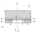
- Figure 1 of the accompanying drawings illustrates an optical filter 30 according to an embodiment of the invention, including a transmissive glass substrate 32, an optical filter layer 34, an epoxy layer 36, and a metal ring 38.
- the filter layer 34 is coated onto and thereby attached to the transmissive substrate 32.
- a light beam 40 directed towards the filter layer 34 is in part transmitted through the filter layer 34 and the transmissive substrate 32 in the form of the transmitted beam 42, and in part reflected from the filter layer 34 in the form of the reflected beam 44.
- the light beam 40 may have a wide range of wavelengths and the filter layer 34 may be made of a material or materials that filter the light so that the transmitted beam 42 includes only light from a selected range of wavelengths within the wider range of wavelengths of the light beam 40.
- the remainder of the light i.e. the wavelengths not transmitted by the beam 42, is reflected in the form of the reflected beam 44 so that the beam 44 includes light having a reflected range of wavelengths not included in the transmitted beam 42.
- Figure 2 illustrates what tends to happen to a center wavelength of the transmitted beam 42 with an increase in temperature. Temperature is given on a horizontal axis in degrees Celsius (°C) and a center wavelength of the transmitted beam 42 is given on a vertical axis in nanometers (nm). The center wavelength of the transmitted beam 42 is plotted along the line 66. The line 66 therefore illustrates what tends to happen to the center wavelength of the transmitted beam 42 due to an increase in temperature and a corresponding increase in the refractive index, in the absence of any effects by the counteracting ring 38. The center wavelength of the transmitted beam 42 is about 1549.235 nm when the filter layer 34 and the transmissive substrate 32 are at 10°C.
- the center wavelength tends to increase substantially linearly with an increase in temperature so that the center wavelength of the transmitted beam 42 tends to be about 1549.38 nm at 85°C. There is thus an increase of 0.15 nm in 75°C, or a linear increase of about 2 pm/°C.
- the tendency for the center wavelength to shift along the line 66 with an increase in temperature is counteracted by the thermal expansion of the ring 38 so that an actual change in the center wavelength is along the line 68.
- the epoxy layer 36 is located between a surface of the filter layer 34 and the counteracting ring 38 so as to attach the counteracting ring 38 to the filter layer 34. Heating of the counteracting ring 38 causes expansion thereof in a direction 70.
- the counteracting ring 38 has a coefficient of thermal expansion of, for example, about 17 ppm/°C which is more than a coefficient of thermal expansion of the filter layer 34 and more than a coefficient of thermal expansion of the transmissive substrate 32.
- a given length of the counteracting ring 38 expands more than a given length of the filter layer 34, and a given length of the counteracting ring 38 expands more than a given length of the transmissive substrate 32.
- the counteracting ring 38 tends to stretch the filter layer 34 and the transmissive substrate 32 in a direction 72 which is in a plane of the optical filter layer 34.
- another counteracting ring may be used, depending on requirement, for example having a coefficient of thermal expansion between 13 ppm/°C and 19 ppm/°C.
- Stretching of the filter layer 34 in the direction 72 by the counteracting ring 38 tends to cause a reduction in thickness of the light filter layer in a direction 74.
- An increase in thickness of the filter layer causes an increase in a center wavelength of the wavelengths of the transmitted beam 42 according to the equation: ⁇ ⁇ c ⁇ ⁇ d/d
- a total change in the center wavelength is expressed as ⁇ c ⁇ ⁇ n / n + ⁇ d/d .
- Heating causes an increase in the refractory index n and, due to the presence of the ring 38, a decrease in the thickness d .
- any positive change in ⁇ n/n can be counteracted by a negative change in ⁇ d / d so that ⁇ ⁇ c remains substantially zero or close to zero.
- heating of the filter layer 34 tends to cause a shift in a center wavelength of the transmission range in one sense or direction, and that the effect of the counteracting ring 38 is to tend to cause a shift in the transmission range in an opposite sense or direction so that the shifts compensate each other, or cancel each other and selected transmission range remains substantially stable.
- the center wavelength of the selected transmission range of the transmitted beam 42 is about 1549.38 nm at 10°C and about the same at 85°C.
- the selected transmission range falls slightly between these extremes to about 1549.37 nm, thus only about 10 pm.
- Figure 3 illustrates an optical filter 100, and two sets of the components 30A and 30B as shown in Figure 1.
- the filter 100 includes a tubular support structure 102, tubed glass capillaries 104 and 106, an input optical fiber 108, a transmission optical fiber 110, a reflection optical fiber 112, a metal holder 114, and two lenses 116 and 118.
- the input optical fiber 108 and the reflection optical fiber 112 are inserted into the glass capillary 104 and terminate at an air gap near the lens 116.
- the glass capillary 104 is rigidly secured to the tubular support structure 102.
- the lens 116 is secured to the glass capillary 104 and one set of the components 30A is attached to the lens 116.
- the set of components 30A is thus unmovably secured to and within the tubular support structure 102.
- the transmission optical fiber 110 is located within the glass capillary 106 and terminates at an air gap near the lens 118.
- the lens 118 is attached to the glass capillary 106 that, in turn, is secured to the tubular support structure 102. The lens 118 is thereby unmovably secured to and within in the tubular support structure 102.
- the counteracting ring 38 of the components 30B is secured within and to the metal holder 114.
- the metal holder 114 is made of the same material as the counteracting ring 308.
- the metal holder 114 is initially movably secured to the tubular support structure 102.
- a device (not shown) pivots the metal holder 114, and therefore also the components 30B, relative to the tubular support structure 102 to a required degree, whereafter the metal holder 114 is secured to the tubular support structure.
- light is transmitted through the input optical fiber 108 into the lens 116.
- the lens 116 focuses the light and also causes a change in direction in the light so that there is an incidence angle between light transmitted through the input optical fiber 108 and light being transmitted through the lens 116.
- Some of the light is reflected by the filter layer 34 of the component 30A and, due to the angle, is transmitted back through the lens 116 to the reflection optical fiber 112.
- the angle thus allows for the light to reach the reflection optical fiber 112. No shift in a center wavelength of transmitted light would occur should the light strike the filter layer 34 of the component 30A at a right angle (at a given temperature). However, the angle also causes a shift in the selected transmission range of light being transmitted through the component 30A.
- the orientation of the component 30B allows for correction in the shift of the selected transmission range.
- the filter layer 34 and the transmissive substrate 32 of the component 30B are also pivoted. These components are pivoted to a degree which ensures that light striking the transmissive substrate 32 of the components 30B is at a correction angle relative to a surface of the transmissive substrate 32, which ensures that there is a return shift in the wavelengths of the transmitted light.
- the light then enters the lens 118 and travels into an end of the transmission optical fiber 110 whereafter the light is transmitted therethrough.
- Any shift in wavelengths of a transmitted beam due to spacing between a center line of the input optical fiber 108 and the reflection optical fiber 112 and a consequent angle at which light strikes the component 30A is thus corrected by the orientation of the component 30B so that a desired range of wavelengths of the light transmits through the transmission optical fiber 110 is maintained.
Landscapes
- Physics & Mathematics (AREA)
- General Physics & Mathematics (AREA)
- Optics & Photonics (AREA)
- Optical Couplings Of Light Guides (AREA)
- Optical Filters (AREA)
Abstract
Description
Claims (10)
- An optical filter comprising:a filter layer of a filter material that transmits a selected transmission range of wavelengths and reflects another selected reflection range of the wavelengths, the filter material having a refractive index, heating of the filter layer tending to cause a shift in the refractive index with a corresponding first shift in a center wavelength of the transmission range; anda counteracting member of a material having a higher coefficient of thermal expansion than the filter material and attached to the filter layer so that upon heating of at least the counteracting member, a given length of the counteracting member expands more than a same length of the filter layer and thereby causes stretching of the filter layer, stretching of the filter layer tending to cause a reduction in thickness of the filter layer with a corresponding second shift in the center wavelength of the transmission range, the second shift being of the opposite sense than the first shift whereby the central wavelength is at least partly stabilized.
- The optical filter of claim 1 wherein the compensating member is a ring defining an aperture, the ring disposed such that at least some of the light transmitted through the filter layer transmits through the aperture in the ring, heating of the counteracting ring causing enlargement of the ring, the ring being of a material having a higher coefficient of thermal expansion than the filter material so that a given length of the counteracting ring expands more than a same length of the filter layer and thereby causes stretching of the filter layer, stretching of the filter layer tending to cause a reduction in thickness of the filter layer with a corresponding decrease in the center wavelength, the selected transmission range thereby being at least in part stabilized.
- The optical filter of claim 1 wherein the material of the counteracting member is a metal.
- The optical filter of claim 1 wherein the material of the member has a coefficient of thermal expansion is at least 14 ppm/°C.
- The optical filter of claim 1 further comprising:a transparent substrate to which the filter layer is attached so that at least some of the light transmits through the transparent substrate in addition to passing through the aperture in the counteracting ring and the filter layer.
- The optical filter of claim 1 further comprising:an input optical fiber for carrying light having a range of wavelengths, and for transmitting the light from an end thereof through the filter layer, and a transmission optical fiber for transmitting light of the selected transmission range.
- The optical filter of claim 6 further comprising:a reflection optical fiber having an end positioned so that the selected reflection range enters the reflection optical fiber to be transmitted through the reflection optical fiber.
- An optical filter comprising:a support structure, a first optical filter layer, a first counteracting ring, an input optical fiber, an output optical fiber and a reflection optical fiber all mounted to the support structure, light from the input optical fiber being directed towards the first filter layer at an incidence angle other than at a right angle to a plane of the first filter layer, the incidence angle resulting in a shift in wavelength of the light transmitting through the first filter layer; anda second filter layer of a filter material secured to the support structure and positioned so that the light is transmitted through the first filter layer, whereafter the light enters the transmission optical fiber, the second filter layer being locatable in a plane which is at a correction angle relative to light before transmitting therethrough, the correction angle resulting in a shift of the wavelength in a direction opposite to the shift due to the incidence angle.
- The optical filter of claim 8 further comprising:a second counteracting ring circumferentially attached to the second filter layer so that at least some of the light transmits through an aperture in the second counteracting ring in addition to transmitting through the second filter layer, heating of the second counteracting ring causing enlargement of the second counteracting ring, the second counteracting ring being of a material having a higher coefficient of thermal expansion than the filter material so that a given length of the second counteracting ring expands more than a same length of the second light filter layer, and thereby causes stretching of the second light filter layer.
- The optical filter of claim 9 further comprising:a holder, the second counteracting ring being secured to the holder and the holder being adjustable relative to the support structure to cause the angle of the plane of the second light filter to be adjusted.
Applications Claiming Priority (2)
| Application Number | Priority Date | Filing Date | Title |
|---|---|---|---|
| US644144 | 2000-08-22 | ||
| US09/644,144 US6469847B1 (en) | 2000-08-22 | 2000-08-22 | Temperature compensated optical filter |
Publications (3)
| Publication Number | Publication Date |
|---|---|
| EP1186915A2 true EP1186915A2 (en) | 2002-03-13 |
| EP1186915A3 EP1186915A3 (en) | 2004-03-24 |
| EP1186915B1 EP1186915B1 (en) | 2008-05-07 |
Family
ID=24583628
Family Applications (1)
| Application Number | Title | Priority Date | Filing Date |
|---|---|---|---|
| EP01306962A Expired - Lifetime EP1186915B1 (en) | 2000-08-22 | 2001-08-16 | Optical filter with temperature stabilised transmission wavelengths |
Country Status (4)
| Country | Link |
|---|---|
| US (1) | US6469847B1 (en) |
| EP (1) | EP1186915B1 (en) |
| CN (1) | CN1236343C (en) |
| CA (1) | CA2355419A1 (en) |
Cited By (1)
| Publication number | Priority date | Publication date | Assignee | Title |
|---|---|---|---|---|
| WO2005093471A1 (en) * | 2004-03-20 | 2005-10-06 | Robert Bosch Gmbh | Filter chip comprising an integrated diaphragm |
Families Citing this family (5)
| Publication number | Priority date | Publication date | Assignee | Title |
|---|---|---|---|---|
| US6785052B2 (en) * | 2001-05-21 | 2004-08-31 | Jds Uniphase Corporation | Stress free and thermally stabilized dielectric fiber |
| US6701040B2 (en) * | 2001-10-15 | 2004-03-02 | Ac Photonics, Inc. | Dense wavelength division multiplexer configuration |
| KR100566015B1 (en) * | 2003-12-18 | 2006-03-30 | 전자부품연구원 | How to package optical components for optical communication |
| CN105589161A (en) * | 2015-12-18 | 2016-05-18 | 中国科学技术大学 | Adjustable constant-temperature optical filter switching apparatus |
| US11320597B1 (en) * | 2021-01-29 | 2022-05-03 | Browave Corporation | Optical device |
Family Cites Families (6)
| Publication number | Priority date | Publication date | Assignee | Title |
|---|---|---|---|---|
| US3039362A (en) * | 1958-05-09 | 1962-06-19 | Ca Nat Research Council | Narrow band interference filter |
| US3393035A (en) * | 1965-06-25 | 1968-07-16 | Canadian Patents Dev | Mounting for mica interference filters |
| US4813756A (en) * | 1988-01-25 | 1989-03-21 | Bell Communications Research, Inc. | Etalon filters for optical channel selection in wavelength division multiplexed fiber systems |
| US6269202B1 (en) * | 1997-10-10 | 2001-07-31 | Dicon Fiberoptics, Inc. | Highly temperature stable filter for fiberoptic applications and system for altering the wavelength or other characteristics of optical devices |
| US6382841B1 (en) * | 2000-03-28 | 2002-05-07 | Optical Coating Laboratory | Optical component coupling and method for manufacturing same |
| US6278549B1 (en) * | 2000-04-17 | 2001-08-21 | Ciena Corporation | Optical filter having a quartz substrate |
-
2000
- 2000-08-22 US US09/644,144 patent/US6469847B1/en not_active Expired - Fee Related
-
2001
- 2001-08-16 EP EP01306962A patent/EP1186915B1/en not_active Expired - Lifetime
- 2001-08-16 CA CA002355419A patent/CA2355419A1/en not_active Abandoned
- 2001-08-22 CN CNB011357517A patent/CN1236343C/en not_active Expired - Fee Related
Cited By (1)
| Publication number | Priority date | Publication date | Assignee | Title |
|---|---|---|---|---|
| WO2005093471A1 (en) * | 2004-03-20 | 2005-10-06 | Robert Bosch Gmbh | Filter chip comprising an integrated diaphragm |
Also Published As
| Publication number | Publication date |
|---|---|
| US6469847B1 (en) | 2002-10-22 |
| EP1186915B1 (en) | 2008-05-07 |
| CN1236343C (en) | 2006-01-11 |
| CN1350195A (en) | 2002-05-22 |
| CA2355419A1 (en) | 2002-02-22 |
| EP1186915A3 (en) | 2004-03-24 |
Similar Documents
| Publication | Publication Date | Title |
|---|---|---|
| US6798948B2 (en) | Method and apparatus for reducing the wavelength dependency of an integrated optical filter | |
| JPH0943440A (en) | Integrated optical multiplexer / demultiplexer | |
| US6775437B2 (en) | Temperature compensated optical waveguide structures | |
| JP2000353856A (en) | Semiconductor laser module | |
| US6816315B1 (en) | Optical path length tuner | |
| CN1934758B (en) | Temperature-tuned filters with prestressed membranes for wavelength tuning of external-cavity laser diodes | |
| EP2133732A2 (en) | Delay interferometer | |
| EP1186915A2 (en) | Optical filter which counteracts a tendancy to shift optical wavelengh with change in temperature | |
| US20110317170A1 (en) | Wedge pair for phase shifting | |
| JP3404031B2 (en) | Integrated optical multiplexer / demultiplexer | |
| US6545826B2 (en) | Thermally compensated wavelength division demultiplexer and multiplexer and method of fabrication thereof | |
| US6185040B1 (en) | Virtually imaged phased array (VIPA) having spacer element and optical length adjusting element | |
| JP5153432B2 (en) | Wavelength locker module | |
| CN100388652C (en) | dispersion compensator | |
| JPH09197179A (en) | Optical circuit and its production | |
| RU2328077C1 (en) | Bidirectional optical coupler | |
| JPH0651113A (en) | Optical band pass filter module | |
| US10656371B2 (en) | Arrangement for supporting an optical component | |
| EP4354678A2 (en) | Integrated end mirror assembly for a fiber ring laser | |
| JP2007272221A (en) | Chromatic dispersion compensator | |
| JP5023703B2 (en) | Variable dispersion compensator | |
| CA2325191A1 (en) | Resonant optical cavity | |
| JP4473917B2 (en) | Optical signal processing device | |
| CN112415489B (en) | Satellite-borne solid gap etalon | |
| JP2006221075A (en) | Variable dispersion compensator |
Legal Events
| Date | Code | Title | Description |
|---|---|---|---|
| PUAI | Public reference made under article 153(3) epc to a published international application that has entered the european phase |
Free format text: ORIGINAL CODE: 0009012 |
|
| AK | Designated contracting states |
Kind code of ref document: A2 Designated state(s): AT BE CH CY DE DK ES FI FR GB GR IE IT LI LU MC NL PT SE TR |
|
| AX | Request for extension of the european patent |
Free format text: AL;LT;LV;MK;RO;SI |
|
| RTI1 | Title (correction) |
Free format text: OPTICAL FILTER WITH TEMPERATURE STABILISED TRANSMISSION WAVELENGTHS |
|
| PUAL | Search report despatched |
Free format text: ORIGINAL CODE: 0009013 |
|
| AK | Designated contracting states |
Kind code of ref document: A3 Designated state(s): AT BE CH CY DE DK ES FI FR GB GR IE IT LI LU MC NL PT SE TR |
|
| AX | Request for extension of the european patent |
Extension state: AL LT LV MK RO SI |
|
| 17P | Request for examination filed |
Effective date: 20040714 |
|
| 17Q | First examination report despatched |
Effective date: 20041006 |
|
| AKX | Designation fees paid |
Designated state(s): GB |
|
| REG | Reference to a national code |
Ref country code: DE Ref legal event code: 8566 |
|
| 17Q | First examination report despatched |
Effective date: 20041006 |
|
| GRAP | Despatch of communication of intention to grant a patent |
Free format text: ORIGINAL CODE: EPIDOSNIGR1 |
|
| GRAS | Grant fee paid |
Free format text: ORIGINAL CODE: EPIDOSNIGR3 |
|
| GRAA | (expected) grant |
Free format text: ORIGINAL CODE: 0009210 |
|
| AK | Designated contracting states |
Kind code of ref document: B1 Designated state(s): GB |
|
| REG | Reference to a national code |
Ref country code: GB Ref legal event code: FG4D |
|
| PGFP | Annual fee paid to national office [announced via postgrant information from national office to epo] |
Ref country code: GB Payment date: 20080827 Year of fee payment: 8 |
|
| PLBE | No opposition filed within time limit |
Free format text: ORIGINAL CODE: 0009261 |
|
| STAA | Information on the status of an ep patent application or granted ep patent |
Free format text: STATUS: NO OPPOSITION FILED WITHIN TIME LIMIT |
|
| 26N | No opposition filed |
Effective date: 20090210 |
|
| GBPC | Gb: european patent ceased through non-payment of renewal fee |
Effective date: 20090816 |
|
| PG25 | Lapsed in a contracting state [announced via postgrant information from national office to epo] |
Ref country code: GB Free format text: LAPSE BECAUSE OF NON-PAYMENT OF DUE FEES Effective date: 20090816 |