EP1186860A1 - Method for identifying measuring points in an optical measuring system - Google Patents
Method for identifying measuring points in an optical measuring system Download PDFInfo
- Publication number
- EP1186860A1 EP1186860A1 EP00810817A EP00810817A EP1186860A1 EP 1186860 A1 EP1186860 A1 EP 1186860A1 EP 00810817 A EP00810817 A EP 00810817A EP 00810817 A EP00810817 A EP 00810817A EP 1186860 A1 EP1186860 A1 EP 1186860A1
- Authority
- EP
- European Patent Office
- Prior art keywords
- targets
- differing
- target
- measuring point
- measuring
- Prior art date
- Legal status (The legal status is an assumption and is not a legal conclusion. Google has not performed a legal analysis and makes no representation as to the accuracy of the status listed.)
- Granted
Links
Images
Classifications
-
- G—PHYSICS
- G01—MEASURING; TESTING
- G01C—MEASURING DISTANCES, LEVELS OR BEARINGS; SURVEYING; NAVIGATION; GYROSCOPIC INSTRUMENTS; PHOTOGRAMMETRY OR VIDEOGRAMMETRY
- G01C11/00—Photogrammetry or videogrammetry, e.g. stereogrammetry; Photographic surveying
-
- G—PHYSICS
- G01—MEASURING; TESTING
- G01B—MEASURING LENGTH, THICKNESS OR SIMILAR LINEAR DIMENSIONS; MEASURING ANGLES; MEASURING AREAS; MEASURING IRREGULARITIES OF SURFACES OR CONTOURS
- G01B11/00—Measuring arrangements characterised by the use of optical techniques
-
- G—PHYSICS
- G01—MEASURING; TESTING
- G01C—MEASURING DISTANCES, LEVELS OR BEARINGS; SURVEYING; NAVIGATION; GYROSCOPIC INSTRUMENTS; PHOTOGRAMMETRY OR VIDEOGRAMMETRY
- G01C15/00—Surveying instruments or accessories not provided for in groups G01C1/00 - G01C13/00
- G01C15/02—Means for marking measuring points
Definitions
- the invention is in the field of metrology and relates to a method according to the generic part of the first independent claim.
- the method serves for identification of measuring points in an optical measuring system.
- Optical measuring systems are used in particular for determining position and orientation of objects in a three dimensional space but also e.g. for determining two dimensional deformation or three dimensional shape.
- optical measuring devices e.g. cameras, laser measuring devices (e.g. laser trackers) or combinations thereof are aimed towards the object to be subjected to the measurement and the spatial position of selected points (measuring points) on the object surface are registered.
- the data gained from such registration is then subjected to suitable computation from which data regarding the spatial position of the selected points are determined from which information regarding position and orientation of the object or other information is deduced.
- targets may be active, i.e. light emitting targets (e.g. light emitting diodes), or passive, i.e. light reflecting targets (e.g. reflectors, white spots on black background, black spots on white background or light spots projected onto the object).
- light emitting targets e.g. light emitting diodes
- passive, i.e. light reflecting targets e.g. reflectors, white spots on black background, black spots on white background or light spots projected onto the object.
- target associated identification is e.g. realized by code patterns e.g. in black and white arranged in the vicinity of the target and usually decoded by template matching (image matching).
- code patterns are e.g. circular segment codes or circular dot codes which codes are binary, i.e. for each code feature position presence of the code feature (e.g. segment or dot) means "one", absence of the code feature means "zero".
- the object of the invention to provide a method for measuring point identification in an optical measurement system which measuring point identification method allows to reduce the disadvantages as described above for target associated identification using known patterns of code features.
- the inventive measuring point identification method is to be very universally applicable, it is to be easily adaptable for supplying besides identification information further useful information and it is to be "readable” not only by template matching methods but also by other, less computation intensive methods.
- each measuring point is marked with the aid of one or more targets each, wherein each target has a specific intensity and/or size.
- each measuring point is identified either by intensity and/or size of a target positioned substantially in the measuring point or by a plurality of targets arranged in a predefined pattern, the pattern of targets being positioned in a predefined relation to the measuring point and encoding the identity of the measuring point by their differing intensities and/or sizes.
- Targets with differing intensity are realized e.g. as light emitting means emitting differing amounts of energy or as passive targets with differing brightness (shades of gray instead of or in addition to black and white, differing intensities of specific color).
- Targets with differing size are realized e.g. as active targets consisting of an accumulation of light emitting means or as passive targets in the form of reflecting or white on black or black on white spots of differing sizes.
- the targets are recorded by a pixel detector (e.g. CCD-detector), i.e. as pixel images comprising advantageously between about 10 and 100 pixels.
- a pixel detector e.g. CCD-detector
- Intensity and/or size of a target may be determined by summing up the intensities of all the pixels comprised in the pixel image of the target (showing an intensity above or below a predetermined limit), the size of a target may be determined by counting the pixels comprised in the image of the target and the intensity may be determined by determining the intensity sensed by the one pixel of the image showing the maximum (or minimum) intensity.
- Pixel images of identification encoding patterns of a plurality of targets having differing intensities and/or sizes can also be decoded by template matching in the same way as done with images of known code patterns associated with measuring points. Identification "by hand” is possible also.
- the advantages of the inventive measuring point identification method over known measuring point identification methods are in particular due to the fact that firstly no target needs ever to be absent (zero intensity or zero size are preferably not used) and to the fact that more than two grades of intensity and/or size are possible resulting in more than binary codes and therefore, larger numbers of permutations.
- Each measuring point can be marked with one target of a specific intensity and/or size or by a plurality of targets arranged in a predetermined pattern wherein each target has a specific intensity and/or size and wherein the pattern encodes the identity of the measuring point.
- All the targets of an encoding target pattern can represent measuring points such that the pattern as a whole constitutes a suitable means for supplying apart from identification information further useful information, e.g. regarding the spatial orientation of the measuring point or of the surface on which it is positioned respectively.
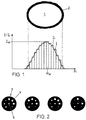
- Figure 1 shows above a bright spot 1 on a darker background 2 representing the image of a target with a specific intensity and size and below the intensity distribution I across the image of the target and intensities I i sensed by pixels P i of a pixel detector in the area of the target image.
- intensity and/or size of the image may be determined by analysis of the intensities I i of the pixels P i comprised within the spot image. For determining size only the number of the pixels P i within the spot image can be determined and for determining the intensity only it may be sufficient to register the maximum intensity I M sensed by pixel P M .
- Figure 2 shows four exemplified circular arrangements 3 of identification targets 4 around a central target 5 marking a measuring point.
- the identification targets 4 have three different sizes such allowing 3 7 , i.e. 2187 permutations.
- the central target 5 may also be included in the identification code by having differing sizes in differing patterns 3 instead of having always the same size as shown in Fig. 2.
- code dot patterns in a set of arrangements of such code dots is always the same as this may be concluded from the set of arrangements as shown in Fig. 2. It is quite possible that one set of arrangements comprises differing patterns.
- the patterns as shown in Fig. 2 are realized e.g. as stickers showing the pattern in black and white, in white and black or in suitably contrasting colors or the code dots may be made of a reflecting material.
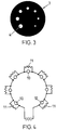
- Figure 3 shows a similar identification pattern 3 with seven identification targets 4 as Fig. 2 in which however, the central target (5) marking the measuring point is missing.
- the data acquired from a pixel image of the arrangement may further serve for determining the spatial position of the arrangement center (measuring point) as well as the orientation of the arrangement (spatial orientation of the measuring point or spatial orientation of a surface on which the measuring point is positioned respectively) if the identification targets 3 are handled like measuring point targets.
- FIG. 4 shows a further exemplified embodiment of a target arrangement to be used in the inventive measuring point identification method.
- This target arrangement comprises light emitting diodes 10 arranged in a ring and wired in parallel with resistors 11 of differing size.
- resistors 11 of differing size.
- Use of the arrangement as shown in Fig. 4 can achieve the same effect as the arrangement shown in Fig. 3.
Landscapes
- Engineering & Computer Science (AREA)
- Physics & Mathematics (AREA)
- General Physics & Mathematics (AREA)
- Radar, Positioning & Navigation (AREA)
- Remote Sensing (AREA)
- Multimedia (AREA)
- Length Measuring Devices By Optical Means (AREA)
- Testing Of Optical Devices Or Fibers (AREA)
Abstract
Description
- The invention is in the field of metrology and relates to a method according to the generic part of the first independent claim. The method serves for identification of measuring points in an optical measuring system.
- Optical measuring systems are used in particular for determining position and orientation of objects in a three dimensional space but also e.g. for determining two dimensional deformation or three dimensional shape. For this purpose, optical measuring devices, e.g. cameras, laser measuring devices (e.g. laser trackers) or combinations thereof are aimed towards the object to be subjected to the measurement and the spatial position of selected points (measuring points) on the object surface are registered. The data gained from such registration is then subjected to suitable computation from which data regarding the spatial position of the selected points are determined from which information regarding position and orientation of the object or other information is deduced.
- The selected points on the object are usually marked with targets. These targets may be active, i.e. light emitting targets (e.g. light emitting diodes), or passive, i.e. light reflecting targets (e.g. reflectors, white spots on black background, black spots on white background or light spots projected onto the object).
- As in most cases a plurality of points is needed for getting enough data for enabling computation of the desired information, it is important that registrations of measuring points can be correlated unequivocally to real measuring points. This correlation can be realized by sequential measurement of selectively illuminated targets, by image matching carried out by an operator, or by giving to each measuring point a unique, machine readable identity. Such machine readable identities may be the position of a measuring point in a predetermined geometric pattern of measuring points or it may be associated to the target marking the measuring point.
- According to the state of the art target associated identification is e.g. realized by code patterns e.g. in black and white arranged in the vicinity of the target and usually decoded by template matching (image matching). Such code patterns are e.g. circular segment codes or circular dot codes which codes are binary, i.e. for each code feature position presence of the code feature (e.g. segment or dot) means "one", absence of the code feature means "zero".
- Such identification systems have some disadvantages. As the codes are binary, the number of permutations is relatively small such necessitating large numbers of code features (segments or dots) for identifying large numbers of targets. In order to prevent misidentification, the code features must be arranged such that they can be recorded separately, i.e. large numbers of such features need a large amount of space. i.e. restrict target density. As the code features are either present or absent only present targets can be used for measurement. Machine reading of such identification patterns necessitates recordation and analysis of a large number of features (e.g. code segments or dots). Furthermore, decoding by template matching needs considerable computing capacity.
- It is the object of the invention to provide a method for measuring point identification in an optical measurement system which measuring point identification method allows to reduce the disadvantages as described above for target associated identification using known patterns of code features. In particular, the inventive measuring point identification method is to be very universally applicable, it is to be easily adaptable for supplying besides identification information further useful information and it is to be "readable" not only by template matching methods but also by other, less computation intensive methods.
- This object is achieved by the method for measuring point identification in an optical measuring system as defined by the claims.
- According to the inventive method the measuring points are marked with the aid of one or more targets each, wherein each target has a specific intensity and/or size. This means that each measuring point is identified either by intensity and/or size of a target positioned substantially in the measuring point or by a plurality of targets arranged in a predefined pattern, the pattern of targets being positioned in a predefined relation to the measuring point and encoding the identity of the measuring point by their differing intensities and/or sizes.
- Targets with differing intensity are realized e.g. as light emitting means emitting differing amounts of energy or as passive targets with differing brightness (shades of gray instead of or in addition to black and white, differing intensities of specific color). Targets with differing size are realized e.g. as active targets consisting of an accumulation of light emitting means or as passive targets in the form of reflecting or white on black or black on white spots of differing sizes.
- The targets are recorded by a pixel detector (e.g. CCD-detector), i.e. as pixel images comprising advantageously between about 10 and 100 pixels. Intensity and/or size of a target may be determined by summing up the intensities of all the pixels comprised in the pixel image of the target (showing an intensity above or below a predetermined limit), the size of a target may be determined by counting the pixels comprised in the image of the target and the intensity may be determined by determining the intensity sensed by the one pixel of the image showing the maximum (or minimum) intensity.
- In the case of a photogrammetric method, all data to be recorded for determination of the intensity and/or size of a target need to be recorded also for determining the center of gravity of the image representing the exact position of the target image on the pixel detector. This means that identification is possible without additional data acquisition.
- Pixel images of identification encoding patterns of a plurality of targets having differing intensities and/or sizes can also be decoded by template matching in the same way as done with images of known code patterns associated with measuring points. Identification "by hand" is possible also.
- The advantages of the inventive measuring point identification method over known measuring point identification methods are in particular due to the fact that firstly no target needs ever to be absent (zero intensity or zero size are preferably not used) and to the fact that more than two grades of intensity and/or size are possible resulting in more than binary codes and therefore, larger numbers of permutations.
- From the above short description it can be gathered that the inventive method for target identification is very widely applicable. Each measuring point can be marked with one target of a specific intensity and/or size or by a plurality of targets arranged in a predetermined pattern wherein each target has a specific intensity and/or size and wherein the pattern encodes the identity of the measuring point. All the targets of an encoding target pattern can represent measuring points such that the pattern as a whole constitutes a suitable means for supplying apart from identification information further useful information, e.g. regarding the spatial orientation of the measuring point or of the surface on which it is positioned respectively.
- The inventive measuring point identification method is further described in connection with the following Figures, wherein:
- Figure 1
- illustrates the determination of intensity and/or size of a target from a pixel image of such a target;
- Figure 2
- shows four code patterns each comprising seven passive identification targets with differing sizes;
- Figure 3
- shows an example of an arrangement of passive targets for encoding the identity of a measuring point and further defining the spatial position and orientation of the measuring point;
- Figure 4
- shows an example of an arrangement of active targets encoding the identity of a measuring point substantially in the same way as the pattern according to Fig. 3.
- Figure 1 shows above a
bright spot 1 on adarker background 2 representing the image of a target with a specific intensity and size and below the intensity distribution I across the image of the target and intensities Ii sensed by pixels Pi of a pixel detector in the area of the target image. As mentioned above, intensity and/or size of the image may be determined by analysis of the intensities Ii of the pixels Pi comprised within the spot image. For determining size only the number of the pixels Pi within the spot image can be determined and for determining the intensity only it may be sufficient to register the maximum intensity IM sensed by pixel PM. - Figure 2 shows four exemplified
circular arrangements 3 of identification targets 4 around acentral target 5 marking a measuring point. The identification targets 4 have three different sizes such allowing 37, i.e. 2187 permutations. Without complication thecentral target 5 may also be included in the identification code by having differing sizes indiffering patterns 3 instead of having always the same size as shown in Fig. 2. - It is not necessary that the code dot patterns in a set of arrangements of such code dots is always the same as this may be concluded from the set of arrangements as shown in Fig. 2. It is quite possible that one set of arrangements comprises differing patterns.
- The patterns as shown in Fig. 2 are realized e.g. as stickers showing the pattern in black and white, in white and black or in suitably contrasting colors or the code dots may be made of a reflecting material.
- Figure 3 shows a
similar identification pattern 3 with seven identification targets 4 as Fig. 2 in which however, the central target (5) marking the measuring point is missing. Besides determination of the measuring point identity, the data acquired from a pixel image of the arrangement may further serve for determining the spatial position of the arrangement center (measuring point) as well as the orientation of the arrangement (spatial orientation of the measuring point or spatial orientation of a surface on which the measuring point is positioned respectively) if theidentification targets 3 are handled like measuring point targets. - Figure 4 shows a further exemplified embodiment of a target arrangement to be used in the inventive measuring point identification method. This target arrangement comprises
light emitting diodes 10 arranged in a ring and wired in parallel withresistors 11 of differing size. Application of three different resistor types results in three different intensities of light emission by the diodes. Use of the arrangement as shown in Fig. 4 can achieve the same effect as the arrangement shown in Fig. 3.
Claims (14)
- Method for identification of measuring points in an optical measuring system in which system a plurality of active or passive targets is used for marking measuring points, characterized in that one or a plurality of targets (4, 10) is associated to each measuring point, the targets having differing intensities and/or differing sizes and that for identification of the measuring points the intensities and/or sizes of the targets (4, 10) are registered.
- Method according to claim 1, characterized in that the targets (4, 10) are imaged in pixel images (1) and that intensities and/or sizes of the pixel images (1) are determined by summing-up intensities (Ii) sensed by pixels (Pi) comprised in the image (1) of a target, by counting the pixels (Pi) comprised in the image (1) of a target or by determining the maximum intensity (IM) sensed by one of the pixels (PM) comprised in the image (1) of a target.
- Method according to one of claims 1 or 2, characterized in that the targets (10) are light emitting means emitting differing amounts of light energy.
- Method according to one of claims 1 or 2 characterized in that the targets (4) are light reflecting spots or white spots on black background or black spots on white background and that the spots have differing sizes.
- Method according to one of claims 1 or 2 characterized in that the targets are spots of differing shades of gray on a white or black background or spots of differing intensity of at least one color.
- Method according to one of claims 1 to 5 characterized in that to each measuring point one target is associated and that the measuring point identity is encoded by the specific intensity and/or size of the target associated with the measuring point.
- Method according to one of claims 1 to 5, characterized in that to each measuring point a plurality of targets (4, 10) is associated, the plurality of targets (4, 10) being arranged in a predetermined pattern (3) and that the measuring point identity is encoded by specific intensities and/or sizes of the targets (4, 10) in the pattern (3).
- Method according to claim 7, characterized in that for computing the spatial position and/or orientation of a measuring point, the spatial position of the targets (4, 10) in the target pattern (3) associated with the measuring point are determined.
- Set of arrangements of a plurality of targets (4, 10) each serving for identifying measuring points in an optical measuring system, characterized in that the targets (4, 10) of each arrangement are arranged in the same pattern (3) or in differing patterns and that the targets (4, 10) have differing intensities and/or sizes.
- Set of arrangements according to claim 9, characterized in that the target pattern (3) is a circle.
- Set of arrangements according to one of claims 9 or 10, characterized in that the targets (10) are light emitting means emitting differing amounts of light energy.
- Set of arrangements according to one of claims 9 or 10, characterized in that the targets (4) are light reflecting spots of differing sizes.
- Set of arrangements according to one of claims 9 or 10, characterized in that the targets (4) are black spots on a white background or white spots on a black background and have differing sizes.
- Set of arrangements according to one of claims 9 or 10, characterized in that the targets are spots of differing gray shades on a white or black background or spots of at least one specific color in differing intensities.
Priority Applications (8)
| Application Number | Priority Date | Filing Date | Title |
|---|---|---|---|
| DE60038556T DE60038556T2 (en) | 2000-09-11 | 2000-09-11 | Method for identifying measuring points in an optical measuring system |
| EP00810817A EP1186860B1 (en) | 2000-09-11 | 2000-09-11 | Method for identifying measuring points in an optical measuring system |
| AT00810817T ATE391895T1 (en) | 2000-09-11 | 2000-09-11 | METHOD FOR IDENTIFYING MEASURING POINTS IN AN OPTICAL MEASURING SYSTEM |
| ES00810817T ES2304938T3 (en) | 2000-09-11 | 2000-09-11 | METHOD FOR IDENTIFYING MEASUREMENT POINTS IN AN OPTICAL MEASUREMENT SYSTEM. |
| JP2002527727A JP5048204B2 (en) | 2000-09-11 | 2001-09-06 | Method for identifying measurement points in an optical measurement system |
| PCT/CH2001/000539 WO2002023127A1 (en) | 2000-09-11 | 2001-09-06 | Method for identifying measuring points in an optical measuring system |
| US10/363,873 US7184151B2 (en) | 2000-09-11 | 2001-09-06 | Method for identifying measuring points in an optical measuring system |
| AU2001283752A AU2001283752A1 (en) | 2000-09-11 | 2001-09-06 | Method for identifying measuring points in an optical measuring system |
Applications Claiming Priority (1)
| Application Number | Priority Date | Filing Date | Title |
|---|---|---|---|
| EP00810817A EP1186860B1 (en) | 2000-09-11 | 2000-09-11 | Method for identifying measuring points in an optical measuring system |
Publications (2)
| Publication Number | Publication Date |
|---|---|
| EP1186860A1 true EP1186860A1 (en) | 2002-03-13 |
| EP1186860B1 EP1186860B1 (en) | 2008-04-09 |
Family
ID=8174901
Family Applications (1)
| Application Number | Title | Priority Date | Filing Date |
|---|---|---|---|
| EP00810817A Expired - Lifetime EP1186860B1 (en) | 2000-09-11 | 2000-09-11 | Method for identifying measuring points in an optical measuring system |
Country Status (8)
| Country | Link |
|---|---|
| US (1) | US7184151B2 (en) |
| EP (1) | EP1186860B1 (en) |
| JP (1) | JP5048204B2 (en) |
| AT (1) | ATE391895T1 (en) |
| AU (1) | AU2001283752A1 (en) |
| DE (1) | DE60038556T2 (en) |
| ES (1) | ES2304938T3 (en) |
| WO (1) | WO2002023127A1 (en) |
Cited By (4)
| Publication number | Priority date | Publication date | Assignee | Title |
|---|---|---|---|---|
| DE10347608A1 (en) * | 2003-10-09 | 2005-05-19 | Daimlerchrysler Ag | Reference mark for photogrammetry/metrophotography has elements for fixing the center of the mark and for variable encoding of data on a circle around the center of the mark |
| WO2008145158A1 (en) * | 2007-05-30 | 2008-12-04 | Trimble Ab | Method for target tracking, and associated target |
| AT514745A3 (en) * | 2014-12-15 | 2016-02-15 | Avl List Gmbh | Method and device for spatial localization of a number of measuring points |
| DE102015102940A1 (en) * | 2015-03-02 | 2016-09-22 | Martin Bünner | Image processing system for automated recognition of structures in a three-dimensional space and marking element for marking structures in a three-dimensional space |
Families Citing this family (16)
| Publication number | Priority date | Publication date | Assignee | Title |
|---|---|---|---|---|
| GB0413827D0 (en) | 2004-06-21 | 2004-07-21 | Renishaw Plc | Scale reading apparatus |
| GB0428165D0 (en) * | 2004-12-23 | 2005-01-26 | Renishaw Plc | Position measurement |
| US7661199B2 (en) * | 2006-05-19 | 2010-02-16 | The Boeing Company | Coded target for use with combination laser and photogrammetry targets |
| FR2945127B1 (en) * | 2009-04-30 | 2012-03-30 | Thales Sa | METHOD AND DEVICE FOR OPTICALLY DETECTING THE MOVEMENTS OF A SOLID IN SPACE |
| DE102010024014B4 (en) | 2010-06-16 | 2016-04-21 | Trimble Jena Gmbh | Target for a geodetic device |
| US9033810B2 (en) * | 2010-08-26 | 2015-05-19 | Blast Motion Inc. | Motion capture element mount |
| US9643049B2 (en) | 2010-08-26 | 2017-05-09 | Blast Motion Inc. | Shatter proof enclosure and mount for a motion capture element |
| US9746354B2 (en) | 2010-08-26 | 2017-08-29 | Blast Motion Inc. | Elastomer encased motion sensor package |
| US10254139B2 (en) | 2010-08-26 | 2019-04-09 | Blast Motion Inc. | Method of coupling a motion sensor to a piece of equipment |
| US9622361B2 (en) | 2010-08-26 | 2017-04-11 | Blast Motion Inc. | Enclosure and mount for motion capture element |
| CN103049731B (en) * | 2013-01-04 | 2015-06-03 | 中国人民解放军信息工程大学 | Decoding method for point-distributed color coding marks |
| CN103033171B (en) * | 2013-01-04 | 2014-10-29 | 中国人民解放军信息工程大学 | Encoding mark based on colors and structural features |
| JP6438311B2 (en) * | 2015-01-27 | 2018-12-12 | 株式会社トプコン | Surveying system, surveying method, surveying instrument and reflection target for surveying |
| CN109544649B (en) * | 2018-11-21 | 2022-07-19 | 武汉珈鹰智能科技有限公司 | Large capacity color coding point coding and its identification method |
| DE102022211112A1 (en) * | 2022-10-20 | 2024-04-25 | Robert Bosch Gesellschaft mit beschränkter Haftung | Method for determining markers for a position and/or orientation of a mobile device in an environment |
| DE102023121873A1 (en) * | 2023-08-16 | 2025-02-20 | L A P Gmbh Laser Applikationen | Method for projecting a laser image onto a workpiece, laser projection system and lighting device |
Citations (4)
| Publication number | Priority date | Publication date | Assignee | Title |
|---|---|---|---|---|
| US4863819A (en) * | 1986-09-11 | 1989-09-05 | Drexler Technology Corporation | Read-only optical data card |
| DE19632058C1 (en) * | 1996-08-09 | 1998-03-05 | Fraunhofer Ges Forschung | Opto electronic identification or target element |
| DE19733466A1 (en) * | 1997-08-02 | 1999-02-04 | Volkswagen Ag | Marking system with coding for measuring purposes |
| US5943783A (en) * | 1992-09-04 | 1999-08-31 | Balco, Incorporated | Method and apparatus for determining the alignment of motor vehicle wheels |
Family Cites Families (22)
| Publication number | Priority date | Publication date | Assignee | Title |
|---|---|---|---|---|
| JPS59114407A (en) * | 1982-12-21 | 1984-07-02 | Fanuc Ltd | Area measurement system of object |
| FR2590681B1 (en) * | 1985-11-27 | 1988-06-24 | Alcatel Espace | SYSTEM FOR LOCATING AN OBJECT PROVIDED WITH AT LEAST ONE PASSIVE SIGHT. |
| US4813436A (en) * | 1987-07-30 | 1989-03-21 | Human Performance Technologies, Inc. | Motion analysis system employing various operating modes |
| NZ231883A (en) * | 1988-12-20 | 1993-04-28 | Australian Meat & Live Stock | Tag with machine-readable optical code |
| US5072294A (en) * | 1989-06-07 | 1991-12-10 | Loredan Biomedical, Inc. | Method and apparatus for analyzing a body having a marker located thereon |
| US5457754A (en) * | 1990-08-02 | 1995-10-10 | University Of Cincinnati | Method for automatic contour extraction of a cardiac image |
| JP2529153B2 (en) * | 1992-07-31 | 1996-08-28 | 株式会社住石ボーリング | Pore curve automatic monitoring system |
| US5982352A (en) * | 1992-09-18 | 1999-11-09 | Pryor; Timothy R. | Method for providing human input to a computer |
| US5395181A (en) * | 1993-05-10 | 1995-03-07 | Microcom Corporation | Method and apparatus for printing a circular or bullseye bar code with a thermal printer |
| US5393970A (en) * | 1993-09-13 | 1995-02-28 | Jeng-Jye Shau | Optical location tracking devices |
| US5734736A (en) * | 1994-06-17 | 1998-03-31 | Trw Inc. | Autonomous rendezvous and docking system and method therefor |
| DE4445386C1 (en) * | 1994-12-20 | 1996-05-02 | Ibm | Method and device for separating foreground information from background information in a template |
| JPH0944620A (en) * | 1995-08-01 | 1997-02-14 | Nippon Direx Kk | Matallic product |
| US5689340A (en) * | 1995-12-06 | 1997-11-18 | Eastman Kodak Company | Apparatus and method for measuring alignment in lenticular media |
| NO301999B1 (en) * | 1995-10-12 | 1998-01-05 | Metronor As | Combination of laser tracker and camera based coordinate measurement |
| JPH09145373A (en) * | 1995-11-20 | 1997-06-06 | Seiwa Consultant Kk | Surveying indicator |
| US5809171A (en) * | 1996-01-05 | 1998-09-15 | Mcdonnell Douglas Corporation | Image processing method and apparatus for correlating a test image with a template |
| JP3497979B2 (en) * | 1996-10-30 | 2004-02-16 | 株式会社山武 | Distance detection device |
| US5900930A (en) * | 1997-10-21 | 1999-05-04 | Eaton Corporation | Angle sensor using a multi-pixel optical device |
| GB9811213D0 (en) * | 1998-05-27 | 1998-07-22 | Camco Int Uk Ltd | Methods of treating preform elements |
| JPH11351870A (en) * | 1998-06-10 | 1999-12-24 | Tokyu Constr Co Ltd | Apparatus and method for automatic measurement of position |
| JP4794708B2 (en) * | 1999-02-04 | 2011-10-19 | オリンパス株式会社 | 3D position and orientation sensing device |
-
2000
- 2000-09-11 DE DE60038556T patent/DE60038556T2/en not_active Expired - Lifetime
- 2000-09-11 EP EP00810817A patent/EP1186860B1/en not_active Expired - Lifetime
- 2000-09-11 ES ES00810817T patent/ES2304938T3/en not_active Expired - Lifetime
- 2000-09-11 AT AT00810817T patent/ATE391895T1/en active
-
2001
- 2001-09-06 JP JP2002527727A patent/JP5048204B2/en not_active Expired - Fee Related
- 2001-09-06 US US10/363,873 patent/US7184151B2/en not_active Expired - Lifetime
- 2001-09-06 AU AU2001283752A patent/AU2001283752A1/en not_active Abandoned
- 2001-09-06 WO PCT/CH2001/000539 patent/WO2002023127A1/en not_active Ceased
Patent Citations (4)
| Publication number | Priority date | Publication date | Assignee | Title |
|---|---|---|---|---|
| US4863819A (en) * | 1986-09-11 | 1989-09-05 | Drexler Technology Corporation | Read-only optical data card |
| US5943783A (en) * | 1992-09-04 | 1999-08-31 | Balco, Incorporated | Method and apparatus for determining the alignment of motor vehicle wheels |
| DE19632058C1 (en) * | 1996-08-09 | 1998-03-05 | Fraunhofer Ges Forschung | Opto electronic identification or target element |
| DE19733466A1 (en) * | 1997-08-02 | 1999-02-04 | Volkswagen Ag | Marking system with coding for measuring purposes |
Cited By (7)
| Publication number | Priority date | Publication date | Assignee | Title |
|---|---|---|---|---|
| DE10347608A1 (en) * | 2003-10-09 | 2005-05-19 | Daimlerchrysler Ag | Reference mark for photogrammetry/metrophotography has elements for fixing the center of the mark and for variable encoding of data on a circle around the center of the mark |
| DE10347608B4 (en) * | 2003-10-09 | 2005-10-13 | Daimlerchrysler Ag | Angular coded measuring marks |
| WO2008145158A1 (en) * | 2007-05-30 | 2008-12-04 | Trimble Ab | Method for target tracking, and associated target |
| US8040528B2 (en) | 2007-05-30 | 2011-10-18 | Trimble Ab | Method for target tracking, and associated target |
| AT514745A3 (en) * | 2014-12-15 | 2016-02-15 | Avl List Gmbh | Method and device for spatial localization of a number of measuring points |
| AT514745B1 (en) * | 2014-12-15 | 2023-03-15 | Avl List Gmbh | Method and device for the spatial localization of a number of measurement points |
| DE102015102940A1 (en) * | 2015-03-02 | 2016-09-22 | Martin Bünner | Image processing system for automated recognition of structures in a three-dimensional space and marking element for marking structures in a three-dimensional space |
Also Published As
| Publication number | Publication date |
|---|---|
| JP5048204B2 (en) | 2012-10-17 |
| EP1186860B1 (en) | 2008-04-09 |
| AU2001283752A1 (en) | 2002-03-26 |
| ATE391895T1 (en) | 2008-04-15 |
| US20040027589A1 (en) | 2004-02-12 |
| DE60038556T2 (en) | 2009-05-28 |
| DE60038556D1 (en) | 2008-05-21 |
| WO2002023127A1 (en) | 2002-03-21 |
| US7184151B2 (en) | 2007-02-27 |
| JP2004508572A (en) | 2004-03-18 |
| ES2304938T3 (en) | 2008-11-01 |
Similar Documents
| Publication | Publication Date | Title |
|---|---|---|
| EP1186860B1 (en) | Method for identifying measuring points in an optical measuring system | |
| AU630408B2 (en) | An optically readable coded target | |
| US7298889B2 (en) | Method and assembly for the photogrammetric detection of the 3-D shape of an object | |
| EP1649423B1 (en) | Method and sytem for the three-dimensional surface reconstruction of an object | |
| KR100899167B1 (en) | Method for reading a symbol having encoded information | |
| CA2187209C (en) | Method and apparatus for decoding two-dimensional symbols in the spatial domain | |
| US6384907B1 (en) | Optical target and apparatus and method for automatic identification thereof | |
| US7398928B2 (en) | Coded target and photogrammetry method using such targets | |
| US7298890B2 (en) | Method and arrangement for the photographically detecting the spatial form of an object | |
| US20110053639A1 (en) | Methods and devices for authenticating a product and a two-dimensional code and novel application of a two-dimensional code | |
| KR20200140827A (en) | Optical product authentication method and system | |
| US7900840B2 (en) | Methods and apparatus for directing bar code positioning for imaging scanning | |
| ES2630736A1 (en) | System and method of detection of defects in specular surfaces or semi-specular through photogrammetric projection (Machine-translation by Google Translate, not legally binding) | |
| US9805455B2 (en) | Rotary encoder system | |
| WO2003042924A1 (en) | Connection of point clouds measured by a computer vision system | |
| CN105556241A (en) | Chassis measurement under ambient light | |
| JP3385579B2 (en) | Shape measuring device and unloading device for black work | |
| KR19980017997A (en) | Identification tags that can be captured electro-optically and signal processing methods for capturing the same | |
| RU2719689C1 (en) | Self-identifying flat calibration object for measuring means of optical range | |
| JPS62128379A (en) | How to read the engraving | |
| HK1083945B (en) | Method for reading a symbol having encoded information |
Legal Events
| Date | Code | Title | Description |
|---|---|---|---|
| PUAI | Public reference made under article 153(3) epc to a published international application that has entered the european phase |
Free format text: ORIGINAL CODE: 0009012 |
|
| AK | Designated contracting states |
Kind code of ref document: A1 Designated state(s): AT BE CH CY DE DK ES FI FR GB GR IE IT LI LU MC NL PT SE |
|
| AX | Request for extension of the european patent |
Free format text: AL;LT;LV;MK;RO;SI |
|
| 17P | Request for examination filed |
Effective date: 20020823 |
|
| AKX | Designation fees paid |
Free format text: AT BE CH CY DE DK ES FI FR GB GR IE IT LI LU MC NL PT SE |
|
| RAP1 | Party data changed (applicant data changed or rights of an application transferred) |
Owner name: LEICA GEOSYSTEMS AG |
|
| 17Q | First examination report despatched |
Effective date: 20050916 |
|
| GRAP | Despatch of communication of intention to grant a patent |
Free format text: ORIGINAL CODE: EPIDOSNIGR1 |
|
| GRAS | Grant fee paid |
Free format text: ORIGINAL CODE: EPIDOSNIGR3 |
|
| GRAA | (expected) grant |
Free format text: ORIGINAL CODE: 0009210 |
|
| AK | Designated contracting states |
Kind code of ref document: B1 Designated state(s): AT BE CH CY DE DK ES FI FR GB GR IE IT LI LU MC NL PT SE |
|
| REG | Reference to a national code |
Ref country code: GB Ref legal event code: FG4D |
|
| REG | Reference to a national code |
Ref country code: CH Ref legal event code: EP |
|
| REG | Reference to a national code |
Ref country code: IE Ref legal event code: FG4D |
|
| REF | Corresponds to: |
Ref document number: 60038556 Country of ref document: DE Date of ref document: 20080521 Kind code of ref document: P |
|
| REG | Reference to a national code |
Ref country code: SE Ref legal event code: TRGR |
|
| REG | Reference to a national code |
Ref country code: CH Ref legal event code: NV Representative=s name: FREI PATENTANWALTSBUERO AG |
|
| NLV1 | Nl: lapsed or annulled due to failure to fulfill the requirements of art. 29p and 29m of the patents act | ||
| PG25 | Lapsed in a contracting state [announced via postgrant information from national office to epo] |
Ref country code: PT Free format text: LAPSE BECAUSE OF FAILURE TO SUBMIT A TRANSLATION OF THE DESCRIPTION OR TO PAY THE FEE WITHIN THE PRESCRIBED TIME-LIMIT Effective date: 20080909 Ref country code: NL Free format text: LAPSE BECAUSE OF FAILURE TO SUBMIT A TRANSLATION OF THE DESCRIPTION OR TO PAY THE FEE WITHIN THE PRESCRIBED TIME-LIMIT Effective date: 20080409 Ref country code: FI Free format text: LAPSE BECAUSE OF FAILURE TO SUBMIT A TRANSLATION OF THE DESCRIPTION OR TO PAY THE FEE WITHIN THE PRESCRIBED TIME-LIMIT Effective date: 20080409 |
|
| REG | Reference to a national code |
Ref country code: ES Ref legal event code: FG2A Ref document number: 2304938 Country of ref document: ES Kind code of ref document: T3 |
|
| ET | Fr: translation filed | ||
| PG25 | Lapsed in a contracting state [announced via postgrant information from national office to epo] |
Ref country code: DK Free format text: LAPSE BECAUSE OF FAILURE TO SUBMIT A TRANSLATION OF THE DESCRIPTION OR TO PAY THE FEE WITHIN THE PRESCRIBED TIME-LIMIT Effective date: 20080409 |
|
| PLBE | No opposition filed within time limit |
Free format text: ORIGINAL CODE: 0009261 |
|
| STAA | Information on the status of an ep patent application or granted ep patent |
Free format text: STATUS: NO OPPOSITION FILED WITHIN TIME LIMIT |
|
| 26N | No opposition filed |
Effective date: 20090112 |
|
| PG25 | Lapsed in a contracting state [announced via postgrant information from national office to epo] |
Ref country code: MC Free format text: LAPSE BECAUSE OF NON-PAYMENT OF DUE FEES Effective date: 20080930 |
|
| PG25 | Lapsed in a contracting state [announced via postgrant information from national office to epo] |
Ref country code: IE Free format text: LAPSE BECAUSE OF NON-PAYMENT OF DUE FEES Effective date: 20080911 |
|
| PG25 | Lapsed in a contracting state [announced via postgrant information from national office to epo] |
Ref country code: CY Free format text: LAPSE BECAUSE OF FAILURE TO SUBMIT A TRANSLATION OF THE DESCRIPTION OR TO PAY THE FEE WITHIN THE PRESCRIBED TIME-LIMIT Effective date: 20080409 |
|
| PG25 | Lapsed in a contracting state [announced via postgrant information from national office to epo] |
Ref country code: LU Free format text: LAPSE BECAUSE OF NON-PAYMENT OF DUE FEES Effective date: 20080911 |
|
| PG25 | Lapsed in a contracting state [announced via postgrant information from national office to epo] |
Ref country code: GR Free format text: LAPSE BECAUSE OF FAILURE TO SUBMIT A TRANSLATION OF THE DESCRIPTION OR TO PAY THE FEE WITHIN THE PRESCRIBED TIME-LIMIT Effective date: 20080710 |
|
| REG | Reference to a national code |
Ref country code: CH Ref legal event code: NV Representative=s name: KAMINSKI HARMANN PATENTANWAELTE AG, LI |
|
| REG | Reference to a national code |
Ref country code: DE Ref legal event code: R082 Ref document number: 60038556 Country of ref document: DE Representative=s name: KAMINSKI HARMANN PATENTANWAELTE AG, LI |
|
| REG | Reference to a national code |
Ref country code: FR Ref legal event code: PLFP Year of fee payment: 17 |
|
| PGFP | Annual fee paid to national office [announced via postgrant information from national office to epo] |
Ref country code: CH Payment date: 20160920 Year of fee payment: 17 Ref country code: GB Payment date: 20160920 Year of fee payment: 17 Ref country code: DE Payment date: 20160921 Year of fee payment: 17 |
|
| PGFP | Annual fee paid to national office [announced via postgrant information from national office to epo] |
Ref country code: FR Payment date: 20160921 Year of fee payment: 17 Ref country code: SE Payment date: 20160920 Year of fee payment: 17 Ref country code: AT Payment date: 20160921 Year of fee payment: 17 |
|
| PGFP | Annual fee paid to national office [announced via postgrant information from national office to epo] |
Ref country code: ES Payment date: 20160916 Year of fee payment: 17 Ref country code: BE Payment date: 20160920 Year of fee payment: 17 |
|
| PGFP | Annual fee paid to national office [announced via postgrant information from national office to epo] |
Ref country code: IT Payment date: 20160922 Year of fee payment: 17 |
|
| REG | Reference to a national code |
Ref country code: DE Ref legal event code: R119 Ref document number: 60038556 Country of ref document: DE |
|
| REG | Reference to a national code |
Ref country code: CH Ref legal event code: PL |
|
| REG | Reference to a national code |
Ref country code: SE Ref legal event code: EUG |
|
| REG | Reference to a national code |
Ref country code: AT Ref legal event code: MM01 Ref document number: 391895 Country of ref document: AT Kind code of ref document: T Effective date: 20170911 |
|
| GBPC | Gb: european patent ceased through non-payment of renewal fee |
Effective date: 20170911 |
|
| REG | Reference to a national code |
Ref country code: BE Ref legal event code: MM Effective date: 20170930 |
|
| REG | Reference to a national code |
Ref country code: FR Ref legal event code: ST Effective date: 20180531 |
|
| PG25 | Lapsed in a contracting state [announced via postgrant information from national office to epo] |
Ref country code: LI Free format text: LAPSE BECAUSE OF NON-PAYMENT OF DUE FEES Effective date: 20170930 Ref country code: CH Free format text: LAPSE BECAUSE OF NON-PAYMENT OF DUE FEES Effective date: 20170930 Ref country code: DE Free format text: LAPSE BECAUSE OF NON-PAYMENT OF DUE FEES Effective date: 20180404 Ref country code: GB Free format text: LAPSE BECAUSE OF NON-PAYMENT OF DUE FEES Effective date: 20170911 |
|
| PG25 | Lapsed in a contracting state [announced via postgrant information from national office to epo] |
Ref country code: BE Free format text: LAPSE BECAUSE OF NON-PAYMENT OF DUE FEES Effective date: 20170930 Ref country code: AT Free format text: LAPSE BECAUSE OF NON-PAYMENT OF DUE FEES Effective date: 20170911 Ref country code: FR Free format text: LAPSE BECAUSE OF NON-PAYMENT OF DUE FEES Effective date: 20171002 Ref country code: IT Free format text: LAPSE BECAUSE OF NON-PAYMENT OF DUE FEES Effective date: 20170911 |
|
| REG | Reference to a national code |
Ref country code: ES Ref legal event code: FD2A Effective date: 20181019 |
|
| PG25 | Lapsed in a contracting state [announced via postgrant information from national office to epo] |
Ref country code: ES Free format text: LAPSE BECAUSE OF NON-PAYMENT OF DUE FEES Effective date: 20170912 |
|
| PG25 | Lapsed in a contracting state [announced via postgrant information from national office to epo] |
Ref country code: SE Free format text: LAPSE BECAUSE OF NON-PAYMENT OF DUE FEES Effective date: 20170912 |