EP1186808A1 - Shift control method for an automatic transmission - Google Patents
Shift control method for an automatic transmission Download PDFInfo
- Publication number
- EP1186808A1 EP1186808A1 EP01120290A EP01120290A EP1186808A1 EP 1186808 A1 EP1186808 A1 EP 1186808A1 EP 01120290 A EP01120290 A EP 01120290A EP 01120290 A EP01120290 A EP 01120290A EP 1186808 A1 EP1186808 A1 EP 1186808A1
- Authority
- EP
- European Patent Office
- Prior art keywords
- engine
- gear ratio
- shift
- transmission
- engine brake
- Prior art date
- Legal status (The legal status is an assumption and is not a legal conclusion. Google has not performed a legal analysis and makes no representation as to the accuracy of the status listed.)
- Granted
Links
- 238000000034 method Methods 0.000 title claims abstract description 11
- 230000005540 biological transmission Effects 0.000 title claims description 29
- 230000009347 mechanical transmission Effects 0.000 claims abstract description 14
- 230000009849 deactivation Effects 0.000 claims abstract description 10
- 239000000446 fuel Substances 0.000 claims description 4
- 230000004044 response Effects 0.000 abstract description 4
- 230000006835 compression Effects 0.000 description 4
- 238000007906 compression Methods 0.000 description 4
- 238000006073 displacement reaction Methods 0.000 description 3
- 230000001133 acceleration Effects 0.000 description 2
- 244000304337 Cuminum cyminum Species 0.000 description 1
- 150000001875 compounds Chemical class 0.000 description 1
- 230000008878 coupling Effects 0.000 description 1
- 238000010168 coupling process Methods 0.000 description 1
- 238000005859 coupling reaction Methods 0.000 description 1
- 230000001934 delay Effects 0.000 description 1
- 238000010586 diagram Methods 0.000 description 1
- 230000007246 mechanism Effects 0.000 description 1
- 230000001360 synchronised effect Effects 0.000 description 1
Images


Classifications
-
- B—PERFORMING OPERATIONS; TRANSPORTING
- B60—VEHICLES IN GENERAL
- B60W—CONJOINT CONTROL OF VEHICLE SUB-UNITS OF DIFFERENT TYPE OR DIFFERENT FUNCTION; CONTROL SYSTEMS SPECIALLY ADAPTED FOR HYBRID VEHICLES; ROAD VEHICLE DRIVE CONTROL SYSTEMS FOR PURPOSES NOT RELATED TO THE CONTROL OF A PARTICULAR SUB-UNIT
- B60W10/00—Conjoint control of vehicle sub-units of different type or different function
- B60W10/04—Conjoint control of vehicle sub-units of different type or different function including control of propulsion units
- B60W10/06—Conjoint control of vehicle sub-units of different type or different function including control of propulsion units including control of combustion engines
-
- B—PERFORMING OPERATIONS; TRANSPORTING
- B60—VEHICLES IN GENERAL
- B60W—CONJOINT CONTROL OF VEHICLE SUB-UNITS OF DIFFERENT TYPE OR DIFFERENT FUNCTION; CONTROL SYSTEMS SPECIALLY ADAPTED FOR HYBRID VEHICLES; ROAD VEHICLE DRIVE CONTROL SYSTEMS FOR PURPOSES NOT RELATED TO THE CONTROL OF A PARTICULAR SUB-UNIT
- B60W10/00—Conjoint control of vehicle sub-units of different type or different function
- B60W10/10—Conjoint control of vehicle sub-units of different type or different function including control of change-speed gearings
- B60W10/11—Stepped gearings
- B60W10/111—Stepped gearings with separate change-speed gear trains arranged in series
-
- B—PERFORMING OPERATIONS; TRANSPORTING
- B60—VEHICLES IN GENERAL
- B60W—CONJOINT CONTROL OF VEHICLE SUB-UNITS OF DIFFERENT TYPE OR DIFFERENT FUNCTION; CONTROL SYSTEMS SPECIALLY ADAPTED FOR HYBRID VEHICLES; ROAD VEHICLE DRIVE CONTROL SYSTEMS FOR PURPOSES NOT RELATED TO THE CONTROL OF A PARTICULAR SUB-UNIT
- B60W10/00—Conjoint control of vehicle sub-units of different type or different function
- B60W10/18—Conjoint control of vehicle sub-units of different type or different function including control of braking systems
- B60W10/196—Conjoint control of vehicle sub-units of different type or different function including control of braking systems acting within the driveline, e.g. retarders
-
- B—PERFORMING OPERATIONS; TRANSPORTING
- B60—VEHICLES IN GENERAL
- B60W—CONJOINT CONTROL OF VEHICLE SUB-UNITS OF DIFFERENT TYPE OR DIFFERENT FUNCTION; CONTROL SYSTEMS SPECIALLY ADAPTED FOR HYBRID VEHICLES; ROAD VEHICLE DRIVE CONTROL SYSTEMS FOR PURPOSES NOT RELATED TO THE CONTROL OF A PARTICULAR SUB-UNIT
- B60W30/00—Purposes of road vehicle drive control systems not related to the control of a particular sub-unit, e.g. of systems using conjoint control of vehicle sub-units
- B60W30/18—Propelling the vehicle
- B60W30/19—Improvement of gear change, e.g. by synchronisation or smoothing gear shift
-
- F—MECHANICAL ENGINEERING; LIGHTING; HEATING; WEAPONS; BLASTING
- F16—ENGINEERING ELEMENTS AND UNITS; GENERAL MEASURES FOR PRODUCING AND MAINTAINING EFFECTIVE FUNCTIONING OF MACHINES OR INSTALLATIONS; THERMAL INSULATION IN GENERAL
- F16H—GEARING
- F16H61/00—Control functions within control units of change-speed- or reversing-gearings for conveying rotary motion ; Control of exclusively fluid gearing, friction gearing, gearings with endless flexible members or other particular types of gearing
- F16H61/21—Providing engine brake control
-
- F—MECHANICAL ENGINEERING; LIGHTING; HEATING; WEAPONS; BLASTING
- F16—ENGINEERING ELEMENTS AND UNITS; GENERAL MEASURES FOR PRODUCING AND MAINTAINING EFFECTIVE FUNCTIONING OF MACHINES OR INSTALLATIONS; THERMAL INSULATION IN GENERAL
- F16H—GEARING
- F16H59/00—Control inputs to control units of change-speed- or reversing-gearings for conveying rotary motion
- F16H59/36—Inputs being a function of speed
- F16H2059/366—Engine or motor speed
-
- F—MECHANICAL ENGINEERING; LIGHTING; HEATING; WEAPONS; BLASTING
- F16—ENGINEERING ELEMENTS AND UNITS; GENERAL MEASURES FOR PRODUCING AND MAINTAINING EFFECTIVE FUNCTIONING OF MACHINES OR INSTALLATIONS; THERMAL INSULATION IN GENERAL
- F16H—GEARING
- F16H59/00—Control inputs to control units of change-speed- or reversing-gearings for conveying rotary motion
- F16H59/36—Inputs being a function of speed
- F16H59/38—Inputs being a function of speed of gearing elements
- F16H59/40—Output shaft speed
-
- F—MECHANICAL ENGINEERING; LIGHTING; HEATING; WEAPONS; BLASTING
- F16—ENGINEERING ELEMENTS AND UNITS; GENERAL MEASURES FOR PRODUCING AND MAINTAINING EFFECTIVE FUNCTIONING OF MACHINES OR INSTALLATIONS; THERMAL INSULATION IN GENERAL
- F16H—GEARING
- F16H59/00—Control inputs to control units of change-speed- or reversing-gearings for conveying rotary motion
- F16H59/68—Inputs being a function of gearing status
- F16H59/70—Inputs being a function of gearing status dependent on the ratio established
-
- F—MECHANICAL ENGINEERING; LIGHTING; HEATING; WEAPONS; BLASTING
- F16—ENGINEERING ELEMENTS AND UNITS; GENERAL MEASURES FOR PRODUCING AND MAINTAINING EFFECTIVE FUNCTIONING OF MACHINES OR INSTALLATIONS; THERMAL INSULATION IN GENERAL
- F16H—GEARING
- F16H61/00—Control functions within control units of change-speed- or reversing-gearings for conveying rotary motion ; Control of exclusively fluid gearing, friction gearing, gearings with endless flexible members or other particular types of gearing
- F16H61/70—Control functions within control units of change-speed- or reversing-gearings for conveying rotary motion ; Control of exclusively fluid gearing, friction gearing, gearings with endless flexible members or other particular types of gearing specially adapted for change-speed gearing in group arrangement, i.e. with separate change-speed gear trains arranged in series, e.g. range or overdrive-type gearing arrangements
Definitions
- the present invention relates to a control method/system for controlling shifting in an at least partially automated mechanical transmission system.
- the present invention relates to the control of shifting in a vehicular automated mechanical transmission system wherein the system senses conditions indicative of a shift from a currently engaged gear ratio (GR) and evaluates, in sequence, the desirability of skip shifts and then single shifts and commands shifts deemed desirable.
- GR currently engaged gear ratio
- the present invention relates to control logic for exaluating shift feasibility and target gear identity in view of built-in engine response delays provided to assure proper engine brake deactivation.
- the control of the present invention provides an improved control for a vehicular automated mechanical transmission system which will sense conditions indicative of shifting from a currently engaged gear ratio, and will evaluate, in sequence, the desirability of large skip shifts, then single skip shifts, and then single shifts, and will command a shift to the first target ratio deemed to be desirable under current vehicle operating conditions.
- the shift feasibility rules comprise a two-part test, (a) can the upshift be completed above a minimum engine speed? and (b) when completed, will the engine, in the target ratio, provide sufficient torque at the drive wheels to allow at least a minimum vehicle acceleration?
- the present invention determines the upshift brake deactivation delay provided for a particular engine and evaluates possible target gear ratios based upon the delay.
- an improved shift control for automated mechanical transmissions which will automatically evaluate and command desirable skip and then single shifts.
- the automated transmission system 10 includes a fuel-controlled engine 12 (such as a well-known diesel engine or the like), a multiple-speed, change-gear transmission 14, and a non-positive coupling 16 (such as a friction master clutch) drivingly interposed between the engine and the input shaft 18 of the transmission.
- the transmission 14 may be of the compound type comprising a main transmission section connected in series with a splitter- and/or range-type auxiliary section. Transmissions of this type, especially as used with heavy-duty vehicles, typically have 9, 10, 12, 13, 16 or 18 forward speeds. Examples of such transmissions may be seen by reference to U.S. Pats. No. 5,390,561 and 5,737,978, the disclosures of which are incorporated herein by reference.
- a transmission output shaft 20 extends outwardly from the transmission 14 and is drivingly connected with the vehicle drive axles 22, usually by means of a prop shaft 24.
- the illustrated master friction clutch 16 includes a driving portion 16A connected to the engine crankshaft/ flywheel and a driven portion 16B coupled to the transmission input shaft 18 and adapted to frictionally engage the driving portion 16A.
- An upshift brake 26 also known as an input shaft brake or inertia brake
- Input shaft or upshift brakes are known in the prior art, as may be seen by reference to U.S. Pats. No. 5,655,407 and 5,713,445.
- a microprocessor-based electronic control unit (or ECU) 28 is provided for receiving input signals 30 and for processing same in accordance with predetermined logic rules to issue command output signals 32 to various system actuators and the like.
- Microprocessor-based controllers of this type are well known, and an example thereof may be seen by reference to U.S. Pat. No. 4,595,986.
- System 10 includes a rotational speed sensor 34 for sensing rotational speed of the engine and providing an output signal (ES) indicative thereof, a rotational speed sensor 36 for sensing the rotational speed of the input shaft 16 and providing an output signal (IS) indicative thereof, and a rotational speed sensor 38 for sensing the rotational speed of the output shaft 20 and providing an output signal (OS) indicative thereof.
- a sensor 40 may be provided for sensing the displacement of the throttle pedal and providing an output signal (THL) indicative thereof.
- a shift control console 42 may be provided for allowing the operator to select an operating mode of the transmission system and for providing an output signal (GR T ) indicative thereof.
- System 10 also may include sensors 44 and 46 for sensing operation of the vehicle foot brake (also called service brakes) and engine brakes, respectively, and for providing signals FB and EB, respectively, indicative thereof.
- vehicle foot brake also called service brakes
- engine brakes respectively
- the master clutch 16 may be controlled by a clutch pedal 48 or by a clutch actuator 50 responding to output signals from the ECU 28. Alternatively, an actuator responsive to control output signals may be provided, which may be overridden by operation of the manual clutch pedal. In the preferred embodiment, the clutch is manually controlled and used only to launch the vehicle (see U.S. Pats. No, 4,850,236; 5,272,939 and 5,425,689).
- the transmission 14 may include a transmission actuator 52, which responds to output signals from the ECU 28 and/or which sends input signals to the ECU 28 indicative of the selected position thereof. Shift mechanisms of this type, often of the so-called X ⁇ Y shifter type, are known in the prior art, as may be seen by reference to U.S. Pats. No.
- Actuator 52 may shift the main and/or auxiliary section of transmission 14.
- the engaged and disengaged condition of clutch 16 may be sensed by a position sensor (not shown) or may be determined by comparing the speeds of the engine (ES) and the input shaft (IS).
- Fueling of the engine is preferably controlled by an electronic engine controller 54, which accepts command signals from and/or provides input signals to the ECU 28.
- the engine controller 54 will communicate with an industry standard data link DL which conforms to well-known industry protocols such as SAE J1922, SAE 1939 and/or ISO 11898.
- the ECU 28 may be incorporated within the engine controller 54.
- Engine 12 is provided with an engine brake, such as an engine compression brake ECB, which may be manually controlled by device 46 and/or automatically controlled.
- the engine brake may be activated by ECU 28 to provide ECB-aided upshifts for quicker upshifted, see U.S. Pat No. 5,655,407, the disclosure of which is incorporated herein by reference.
- T ECBDEACTIVATE ECB deactivation delay
- Fig. 2 is a graphical representation of shift point profiles utilized to determine when shift commands should be issued by the ECU 28 to the shift actuator 52.
- Solid line 60 is the default upshift profile
- solid line 62 is the default downshift profile.
- an upshift of transmission 14 should be commanded
- a downshift should be commanded. If the vehicle is operating in between profiles 60 and 62, no shifting of the transmission is then required.
- Shift profile 60 is a graphical representation of the engine speeds at which upshifts from a currently engaged ratio (GR) are indicated (ES U/S ) for various degrees of throttle displacement ( i.e. , demand).
- Shift profile 62 is a graphical representation of the engine speeds at which downshifts are indicated (ES D/S )
- GR TARGET a sequence is initiated for identifying the desirable upshift target ratio (GR TARGET ), if any.
- the control in sequence, will evaluate skip and then single upshifts for desirability and command an upshift to the first potential target ratio deemed desirable.
- a maximum time for completion of an upshift is established based upon considerations for shift quality, vehicle performance, etc. For heavy-duty trucks, by way of example, this time value may have a value of about 1.0 to 2.0 seconds.
- the expected time required to complete the shift and/or to complete the shift and then resume fueling the engine is an important control parameter.
- the control logic takes into account that in shifts occurring when the engine brake is active, (usually before a coasting downshift) will take longer because fuel control to break torque (see U.S. Pat. No. 4,850,236) will commence until after the compression brake deactivation delay (T ECBDEACTIVATE) has expired and, after an ECB-assisted upshift, the engine will not begin to be refueled to increase torque until after the compression brake deactivation delay has expired.
- T ECBDEACTIVATE compression brake deactivation delay
- the value of the deal may be programmed into the system controller (28) logic upon assembly of the system, may be read on the datalink and/or may be imperically determined.
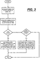
- control of the present invention is shown in flow chart format in Fig. 3.
- an improved control system/method for controlling upshifting in an at least partially automated mechanical transmission system in a vehicle preferably having a manually operated engine brake system is provided.
Landscapes
- Engineering & Computer Science (AREA)
- Mechanical Engineering (AREA)
- Chemical & Material Sciences (AREA)
- Combustion & Propulsion (AREA)
- Transportation (AREA)
- General Engineering & Computer Science (AREA)
- Automation & Control Theory (AREA)
- Control Of Transmission Device (AREA)
Abstract
Description
- This application is related to copending U.S. Serial No's. 09/231,951 titled AUTOMATED TRANSMISSION DOWNSHIFT CONTROL and 09/232,252 titled AUTOMATED TRANSMISSION UPSHIFT CONTROL, both filed January 14, 1999 and assigned to EATON CORPORATION, assignee of this application.
- This application is also related to copending U.S. Serial No. 09/563,097 titled AUTOMATED TRANSMISSION UPSHIFT CONTROL, filed May 2, 2000 and assigned to Eaton Corporation.
- The present invention relates to a control method/system for controlling shifting in an at least partially automated mechanical transmission system. In particular, the present invention relates to the control of shifting in a vehicular automated mechanical transmission system wherein the system senses conditions indicative of a shift from a currently engaged gear ratio (GR) and evaluates, in sequence, the desirability of skip shifts and then single shifts and commands shifts deemed desirable.
- More particularly, the present invention relates to control logic for exaluating shift feasibility and target gear identity in view of built-in engine response delays provided to assure proper engine brake deactivation.
- Fully or partially automated mechanical transmission systems for vehicular use are known in the prior art, as may be seen by reference to U.S. Pats. No. 4,361,060; 4,648,290; 4,722,248; 4,850,236; 5,389,053; 5,487,004; 5,435,212 and 5,755,639. The use of engine brakes (also known as compression brakes, exhaust brakes or Jake brakes) and transmission controls utilizing same are known in the prior art, as may be seen by reference to U.S. Pats. No. 5,409,432 and 5,425,689, the disclosures of which are incorporated herein by reference.
- Controls for automated mechanical transmission systems, especially wherein shifting is accomplished while maintaining the master clutch engaged, wherein single and/or skip shift feasibility is evaluated are known in the prior art, as may be seen by reference to U.S. Pats. No. 4,576,065; 4,916,979; 5,335,566; 5,425,689; 5,272,939; 5,479,345; 5,533,946; 5,582,069; 5,620,392; 5,489,247; 5,490,063 and 5,509,867, the disclosures of which are incorporated herein by reference.
- It is also known that manufacturers of diesel engines for heavy-duty trucks, such as Caterpillar, Cummins, Detroit Diesel, etc., build in a response delay in their electronically controlled engines to allow proper engine brake deactivation. This is done to prevent fueling of the engine if the brake is still active which might cause valve and/or engine damage. This delay typically varies (from about 100 ms to about 500 ms) depending on the type of engine and/or engine brake.
- The control of the present invention provides an improved control for a vehicular automated mechanical transmission system which will sense conditions indicative of shifting from a currently engaged gear ratio, and will evaluate, in sequence, the desirability of large skip shifts, then single skip shifts, and then single shifts, and will command a shift to the first target ratio deemed to be desirable under current vehicle operating conditions.
- In a preferred embodiment of the present invention, by setting (i) a maximum acceptable shift time for completing upshifts and (ii) upshift feasibility rules to determine if a proposed shift is feasible under current vehicle operating conditions. The shift feasibility rules comprise a two-part test, (a) can the upshift be completed above a minimum engine speed? and (b) when completed, will the engine, in the target ratio, provide sufficient torque at the drive wheels to allow at least a minimum vehicle acceleration?
- The present invention, determines the upshift brake deactivation delay provided for a particular engine and evaluates possible target gear ratios based upon the delay.
- The above is accomplished by determining that shifts initiated with the engine brake active (typically only coasting downshifts) and engine brake aided upshifts will take a longer time to complete due to the built in engine brake deactivation delay.
- Accordingly, an improved shift control for automated mechanical transmissions is provided which will automatically evaluate and command desirable skip and then single shifts.
- This and other objects and advantages of the present invention will become apparent from a reading of the following description of the preferred embodiment taken in connection with the attached drawings.
-
- Fig. 1 is a schematic illustration, in block diagram format, of an automated mechanical transmission system utilizing the control of the present invention.
- Fig. 2 is a schematic illustration, in graphical format, illustrating shift point profiles for the transmission system of Fig. 1 according to the present invention.
- Fig. 3 is a schematic illustration , in flow chart format, of the control of the present invention.
-
- An at least partially automated mechanical transmission system intended for vehicular use is schematically illustrated in Fig. 1. The automated transmission system 10 includes a fuel-controlled engine 12 (such as a well-known diesel engine or the like), a multiple-speed, change-
gear transmission 14, and a non-positive coupling 16 (such as a friction master clutch) drivingly interposed between the engine and theinput shaft 18 of the transmission. Thetransmission 14 may be of the compound type comprising a main transmission section connected in series with a splitter- and/or range-type auxiliary section. Transmissions of this type, especially as used with heavy-duty vehicles, typically have 9, 10, 12, 13, 16 or 18 forward speeds. Examples of such transmissions may be seen by reference to U.S. Pats. No. 5,390,561 and 5,737,978, the disclosures of which are incorporated herein by reference. - A
transmission output shaft 20 extends outwardly from thetransmission 14 and is drivingly connected with thevehicle drive axles 22, usually by means of aprop shaft 24. The illustratedmaster friction clutch 16 includes adriving portion 16A connected to the engine crankshaft/ flywheel and a drivenportion 16B coupled to thetransmission input shaft 18 and adapted to frictionally engage thedriving portion 16A. An upshift brake 26 (also known as an input shaft brake or inertia brake) may be used for selectively decelerating the rotational speed of theinput shaft 18 for more rapid upshifting, as is well known. Input shaft or upshift brakes are known in the prior art, as may be seen by reference to U.S. Pats. No. 5,655,407 and 5,713,445. - A microprocessor-based electronic control unit (or ECU) 28 is provided for receiving
input signals 30 and for processing same in accordance with predetermined logic rules to issuecommand output signals 32 to various system actuators and the like. Microprocessor-based controllers of this type are well known, and an example thereof may be seen by reference to U.S. Pat. No. 4,595,986. - System 10 includes a
rotational speed sensor 34 for sensing rotational speed of the engine and providing an output signal (ES) indicative thereof, arotational speed sensor 36 for sensing the rotational speed of theinput shaft 16 and providing an output signal (IS) indicative thereof, and arotational speed sensor 38 for sensing the rotational speed of theoutput shaft 20 and providing an output signal (OS) indicative thereof. Asensor 40 may be provided for sensing the displacement of the throttle pedal and providing an output signal (THL) indicative thereof. Ashift control console 42 may be provided for allowing the operator to select an operating mode of the transmission system and for providing an output signal (GRT) indicative thereof. - As is known, if the clutch is engaged, the rotational speed of the engine may be determined from the speed of the input shaft and/or the speed of the output shaft and the engaged transmission ratio (ES = IS = OS*GR).
- System 10 also may include
sensors - The
master clutch 16 may be controlled by aclutch pedal 48 or by aclutch actuator 50 responding to output signals from theECU 28. Alternatively, an actuator responsive to control output signals may be provided, which may be overridden by operation of the manual clutch pedal. In the preferred embodiment, the clutch is manually controlled and used only to launch the vehicle (see U.S. Pats. No, 4,850,236; 5,272,939 and 5,425,689). Thetransmission 14 may include atransmission actuator 52, which responds to output signals from theECU 28 and/or which sends input signals to theECU 28 indicative of the selected position thereof. Shift mechanisms of this type, often of the so-called X―Y shifter type, are known in the prior art, as may be seen by reference to U.S. Pats. No. 5,305,240 and 5,219,391.Actuator 52 may shift the main and/or auxiliary section oftransmission 14. The engaged and disengaged condition ofclutch 16 may be sensed by a position sensor (not shown) or may be determined by comparing the speeds of the engine (ES) and the input shaft (IS). - Fueling of the engine is preferably controlled by an
electronic engine controller 54, which accepts command signals from and/or provides input signals to theECU 28. Preferably, theengine controller 54 will communicate with an industry standard data link DL which conforms to well-known industry protocols such as SAE J1922, SAE 1939 and/or ISO 11898. The ECU 28 may be incorporated within theengine controller 54. -
Engine 12 is provided with an engine brake, such as an engine compression brake ECB, which may be manually controlled bydevice 46 and/or automatically controlled. The engine brake may be activated by ECU 28 to provide ECB-aided upshifts for quicker upshifted, see U.S. Pat No. 5,655,407, the disclosure of which is incorporated herein by reference. - As is known, to prevent damage to the engine and/or engine valves caused by fueling the engine while the engine brake is active, a time delay is provided after the ECB is deactivated during which the engine is not fueled regardless of fueling commands on the data link. This ECB deactivation delay (TECBDEACTIVATE) is typically in the range of 100 ms to 500 ms and varies with engine and/or ECB supplier.
- As is known, for automated shifting, the
ECU 28 must determine when upshifts and downshifts are required and if a single or skip shift is desirable (see U.S. Pats. No. 4,361,060; 4,576,065; 4,916,979 and 4,947,331). - Fig. 2 is a graphical representation of shift point profiles utilized to determine when shift commands should be issued by the
ECU 28 to theshift actuator 52.Solid line 60 is the default upshift profile, whilesolid line 62 is the default downshift profile. As is known, if the vehicle is operating to the right ofupshift profile 60, an upshift oftransmission 14 should be commanded, while if the vehicle is operating to the left ofdownshift profile 62, a downshift should be commanded. If the vehicle is operating in betweenprofiles -
Shift profile 60 is a graphical representation of the engine speeds at which upshifts from a currently engaged ratio (GR) are indicated (ESU/S) for various degrees of throttle displacement (i.e., demand).Shift profile 62 is a graphical representation of the engine speeds at which downshifts are indicated (ES D/S) - According to the control of a preferred embodiment of the present invention, if an upshift from a currently engaged ratio (GR) is required (i.e., if at current throttle displacement engine speed (ES) is greater than the upshift engine speed (ESU/S) on shift point profile 60), a sequence is initiated for identifying the desirable upshift target ratio (GRTARGET), if any. The control, in sequence, will evaluate skip and then single upshifts for desirability and command an upshift to the first potential target ratio deemed desirable.
- A maximum time for completion of an upshift is established based upon considerations for shift quality, vehicle performance, etc. For heavy-duty trucks, by way of example, this time value may have a value of about 1.0 to 2.0 seconds.
- A two-part feasibility test is established:
- (1) Will the engine speed be at a synchronous value above a preselected minimum engine speed ESMIN, given current/assumed engine and vehicle deceleration rates? The ESMIN, by way of example, is selected at about 1100 to 1300 rpm, which for a typical heavy-duty diesel engine is at or near a peak torque rpm. The engine deceleration rate may be evaluated both with or without the use of engine braking. This logic may be appreciated by reference by U.S. Pats. No. 5,335,566 and 5,425,689, the disclosures of which are incorporated herein by reference. Use of engine brakes (also called exhaust and Jake brakes) to enhance upshifting is known, as may be seen by reference to U.S. Pat. No. 5,409,432; and
- (2) At completion of a proposed upshift, will torque at the drive wheels provide sufficient torque for at least minimal vehicle acceleration? (See U.S. Pats. No. 5,272,939 and 5,479,345, the disclosures of which are incorporated herein by reference.
-
- If one or both of these parts of the feasibility test are not satisfied, the upshift to an evaluated target ratio (GR + 1, 2, 3,...) is not feasible and will not be commanded.
- Similar logic is utilized to evaluate the feasibility of skip and then single downshifts (see copending U.S. Serial No. 09/231,951).
- In evaluating the desirability and feasibility of engaging a particular potential target gear ratio, the expected time required to complete the shift and/or to complete the shift and then resume fueling the engine, is an important control parameter.
- According to the present invention, the control logic takes into account that in shifts occurring when the engine brake is active, (usually before a coasting downshift) will take longer because fuel control to break torque (see U.S. Pat. No. 4,850,236) will commence until after the compression brake deactivation delay (TECBDEACTIVATE) has expired and, after an ECB-assisted upshift, the engine will not begin to be refueled to increase torque until after the compression brake deactivation delay has expired.
- The value of the deal may be programmed into the system controller (28) logic upon assembly of the system, may be read on the datalink and/or may be imperically determined.
- Accordingly, upon sensing a shift to be initiated with the engine brake active and/or if evaluating a potential engine brake assisted shift is evaluated on the basis of requiring an extended period of time to account for the built in engine response delay.
- The control of the present invention is shown in flow chart format in Fig. 3.
- Accordingly, it may be seen that an improved control system/method for controlling upshifting in an at least partially automated mechanical transmission system in a vehicle preferably having a manually operated engine brake system is provided.
- Although the present invention has been described with a certain degree of particularity, it is understood that the description of the preferred embodiment is by way of example only and that numerous changes to form and detail are possible without departing from the spirit and scope of the invention as hereinafter claimed.
Claims (3)
- A method for controlling automatic upshifting in a vehicular automated mechanical transmission system (10) for a vehicle comprising a fuel-controlled engine (12), an engine brake (ECB), a multiple-speed mechanical transmission (14), and a controller (28) for receiving input signals (30) including one or more of signals indicative of engine speed (ES), engaged gear ratio (GR) and vehicle speed (OS), and to process said input signals in accordance with with logic rules to issue command output signals (32) to transmission system actuators including a transmission actuator (52) effective to shift said transmission, and an engine controller (54) effective to control fueling of said engine, said engine controller adapted to delay, for a set period of time (TECBOEACTIVATE) increased fueling of the engine after deactivation of said engine brake, said method characterized by:
if said engine brake is active, determining if shifts from a currently engaged gear ratio into a potential target gear ratio are feasible based upon an expected time to complete said shift into said potential target gear ratio, said expected time determined in accordance with said set period of time. - A method for controlling automatic upshifting in a vehicular automated mechanical transmission system (10) for a vehicle comprising a fuel-controlled engine (12), an engine brake (ECB), a multiple-speed mechanical transmission (14), and a controller (28) for receiving input signals (30) including one or more of signals indicative of engine speed (ES), engaged gear ratio (GR) and vehicle speed (OS), and to process said input signals in accordance with with logic rules to issue command output signals (32) to transmission system actuators including a transmission actuator (52) effective to shift said transmission, and an engine controller (54) effective to control fueling of said engine, said engine controller adapted to delay, for a set period of time (TECBOEACTIVATE) increased fueling of the engine after deactivation of said engine brake, said method characterized by:
determining if engine brake assisted upshifts from a currently engaged gear ratio into a potential target gear ratio are feasible based upon an expected time to complete said shift into said potential target ratio and to refuel said engine to a selected output torque, said expected time determined in accordance with said set period of time. - The method of claim 1 further comprising:
determining if engine brake assisted upshifts from a currently engaged gear ratio into a potential target gear ratio are feasible based upon an expected time to complete said shift into said potential target ratio and to refuel said engine to a selected output torque, said expected time determined in accordance with said set period of time.
Applications Claiming Priority (2)
| Application Number | Priority Date | Filing Date | Title |
|---|---|---|---|
| US660319 | 2000-09-12 | ||
| US09/660,319 US6491603B1 (en) | 2000-09-12 | 2000-09-12 | Automated transmission shift control |
Publications (2)
| Publication Number | Publication Date |
|---|---|
| EP1186808A1 true EP1186808A1 (en) | 2002-03-13 |
| EP1186808B1 EP1186808B1 (en) | 2004-01-14 |
Family
ID=24649035
Family Applications (1)
| Application Number | Title | Priority Date | Filing Date |
|---|---|---|---|
| EP01120290A Expired - Lifetime EP1186808B1 (en) | 2000-09-12 | 2001-08-24 | Shift control method for an automatic transmission |
Country Status (4)
| Country | Link |
|---|---|
| US (1) | US6491603B1 (en) |
| EP (1) | EP1186808B1 (en) |
| BR (1) | BR0104995A (en) |
| DE (1) | DE60101768T2 (en) |
Families Citing this family (4)
| Publication number | Priority date | Publication date | Assignee | Title |
|---|---|---|---|---|
| KR100435649B1 (en) * | 2001-05-04 | 2004-06-12 | 현대자동차주식회사 | Method df controlling shift of automatic transmission for vehicles |
| US20050109141A1 (en) * | 2003-11-25 | 2005-05-26 | Devore James H. | Automated mechanical transmission system |
| DE102011008597A1 (en) * | 2011-01-14 | 2012-07-19 | GM Global Technology Operations LLC (n. d. Ges. d. Staates Delaware) | Method and means for controlling the downshift |
| AU2016260442B2 (en) * | 2015-05-14 | 2020-01-30 | Eaton Intelligent Power Limited | Control system for low speed positioning and pacing for on/off highway vehicles |
Citations (3)
| Publication number | Priority date | Publication date | Assignee | Title |
|---|---|---|---|---|
| EP0670440A1 (en) * | 1994-01-07 | 1995-09-06 | Eaton Corporation | Engine brake enhanced upshift control method/system |
| EP1013973A2 (en) * | 1998-11-13 | 2000-06-28 | Eaton Corporation | Independent control of transmission-side and engine-side retarding devices during ratio changes |
| EP1020663A2 (en) * | 1999-01-14 | 2000-07-19 | Eaton Corporation | Automated transmission upshift control |
Family Cites Families (29)
| Publication number | Priority date | Publication date | Assignee | Title |
|---|---|---|---|---|
| US4361060A (en) | 1978-01-24 | 1982-11-30 | Smyth Robert Ralston | Mechanical automatic transmission |
| GB8418749D0 (en) | 1984-07-23 | 1984-08-30 | Eaton Ltd | Semi-automatic transmission control |
| US4595986A (en) | 1984-10-09 | 1986-06-17 | Eaton Corporation | Method for control of automatic mechanical transmission system utilizing a microprocessor based electronic controller |
| US4850236A (en) | 1987-11-20 | 1989-07-25 | Eaton Corporation | Vehicle drive line shift control system and method |
| US4947331A (en) | 1988-07-25 | 1990-08-07 | Eaton Corporation | Upshift logic |
| US5444623A (en) * | 1991-07-26 | 1995-08-22 | Eaton Corporation | Reengagement control/method for mechanical transmission system with automatic shift implementation |
| US5219391A (en) | 1991-12-06 | 1993-06-15 | Eaton Corporation | Transmission shifter having automatic adjustment of control parameters |
| US5172609A (en) | 1992-03-02 | 1992-12-22 | Saturn Corporation | Gradeability-based shift pattern control for an automatic transmission |
| US5489247A (en) | 1992-07-06 | 1996-02-06 | Eaton Corporation | Adaptive shift control method/system for modifying engine delay rate or vehicle coast deceleration during upshifts |
| US5272939B1 (en) | 1992-07-06 | 1994-12-06 | Eaton Corp | Shift enable control method/system |
| US5335566A (en) | 1992-07-06 | 1994-08-09 | Eaton Corporation | Shift control method/system |
| US5435212A (en) | 1992-10-30 | 1995-07-25 | Eaton Corporation | Semi-automatic shift implementation |
| US5390561A (en) | 1993-05-20 | 1995-02-21 | Eaton Corporation | Compound transmission |
| US5389053A (en) | 1993-07-21 | 1995-02-14 | Eaton Corporation | System and method for sliding clutch engagement under tooth butt or torque lock conditions |
| US5409432A (en) | 1993-08-10 | 1995-04-25 | Eaton Corporation | Control system/method for engine brake assisted shifting |
| US5487004A (en) | 1993-10-29 | 1996-01-23 | Eaton Corporation | Control system/method for automated mechanical transmission systems |
| US5479345A (en) | 1993-11-02 | 1995-12-26 | Eaton Corporation | Method and apparatus for selecting shift points in an automated mechanical transmission |
| US5490063A (en) | 1994-02-07 | 1996-02-06 | Eaton Corporation | Control method/system including determination of an updated value indicative of gross combination weight of vehicles |
| SE502550C2 (en) * | 1994-03-18 | 1995-11-13 | Saab Scania Ab | Fuel flow control method and apparatus in connection with nerve shifts |
| US5533946A (en) | 1994-04-08 | 1996-07-09 | Eaton Corporation | Engine deceleration determination method/system for updating a control parameter |
| US5509867A (en) | 1994-05-16 | 1996-04-23 | Eaton Corporation | Engine flywheel torque determination method/system |
| US5582069A (en) | 1994-05-16 | 1996-12-10 | Eaton Corporation | Engine accessory torque and engine deceleration rate determination method/system |
| GB9411494D0 (en) | 1994-06-08 | 1994-07-27 | Eaton Corp | System and method for decreasing ratio changing time in electronically enhanced powertrain systems |
| US5737978A (en) | 1996-04-10 | 1998-04-14 | Eaton Corporation | Two-piece housing for compound transmission |
| US5713445A (en) | 1996-07-22 | 1998-02-03 | Eaton Corporation | Transmission inertia brake with self energizing |
| US5743143A (en) | 1996-08-09 | 1998-04-28 | Eaton Corporation | Transmission shifting mechanism and position sensor |
| JPH10103098A (en) * | 1996-10-01 | 1998-04-21 | Unisia Jecs Corp | Vehicle control device |
| US5766111A (en) | 1997-02-05 | 1998-06-16 | Eaton Corporation | Automode-to-neutral logic |
| JP3409669B2 (en) * | 1997-03-07 | 2003-05-26 | 日産自動車株式会社 | Transmission control device for continuously variable transmission |
-
2000
- 2000-09-12 US US09/660,319 patent/US6491603B1/en not_active Expired - Lifetime
-
2001
- 2001-08-24 EP EP01120290A patent/EP1186808B1/en not_active Expired - Lifetime
- 2001-08-24 DE DE60101768T patent/DE60101768T2/en not_active Expired - Fee Related
- 2001-08-29 BR BR0104995-0A patent/BR0104995A/en not_active IP Right Cessation
Patent Citations (3)
| Publication number | Priority date | Publication date | Assignee | Title |
|---|---|---|---|---|
| EP0670440A1 (en) * | 1994-01-07 | 1995-09-06 | Eaton Corporation | Engine brake enhanced upshift control method/system |
| EP1013973A2 (en) * | 1998-11-13 | 2000-06-28 | Eaton Corporation | Independent control of transmission-side and engine-side retarding devices during ratio changes |
| EP1020663A2 (en) * | 1999-01-14 | 2000-07-19 | Eaton Corporation | Automated transmission upshift control |
Also Published As
| Publication number | Publication date |
|---|---|
| BR0104995A (en) | 2002-05-21 |
| EP1186808B1 (en) | 2004-01-14 |
| DE60101768D1 (en) | 2004-02-19 |
| DE60101768T2 (en) | 2004-11-04 |
| US6491603B1 (en) | 2002-12-10 |
Similar Documents
| Publication | Publication Date | Title |
|---|---|---|
| EP1020663B1 (en) | Automated transmission upshift control | |
| EP1020664B1 (en) | Automated transmission downshift control | |
| US6113516A (en) | Adaptive automated transmission upshift control | |
| EP1152172B1 (en) | Automated transmission upshift control | |
| EP1070625B1 (en) | Starting and driveline shock protection control method and system | |
| US6123644A (en) | Adaptive anti-hunt logic for automated transmission downshift control | |
| EP1392989B1 (en) | Automated transmission upshift brake control | |
| US6375596B1 (en) | Control to determine input shaft direction of rotation | |
| US6146310A (en) | Adaptive automated transmission downshift control | |
| EP1158218B1 (en) | Automated transmission upshift control with upshift brake thermal protection | |
| EP1186808B1 (en) | Shift control method for an automatic transmission | |
| EP1514041B1 (en) | Method of detecting false neutral in an automated transmission system | |
| EP1013497B1 (en) | Automated transmission downshift control | |
| US6231474B1 (en) | Automated transmission downshift control | |
| US7491152B2 (en) | System and method for controlling engagement of a clutch | |
| US6461272B1 (en) | Vehicle synchronization algorithm for driveline protection | |
| EP0985856B1 (en) | Method/system for controlling upshifting in an automated mechanical transmission system | |
| EP0697508A2 (en) | Throttle control system in combination with an automated mechanical transmission system |
Legal Events
| Date | Code | Title | Description |
|---|---|---|---|
| PUAI | Public reference made under article 153(3) epc to a published international application that has entered the european phase |
Free format text: ORIGINAL CODE: 0009012 |
|
| AK | Designated contracting states |
Kind code of ref document: A1 Designated state(s): AT BE CH CY DE DK ES FI FR GB GR IE IT LI LU MC NL PT SE TR Kind code of ref document: A1 Designated state(s): DE FR GB IT SE |
|
| AX | Request for extension of the european patent |
Free format text: AL;LT;LV;MK;RO;SI |
|
| 17P | Request for examination filed |
Effective date: 20020906 |
|
| AKX | Designation fees paid |
Free format text: DE FR GB IT SE |
|
| 17Q | First examination report despatched |
Effective date: 20021211 |
|
| GRAP | Despatch of communication of intention to grant a patent |
Free format text: ORIGINAL CODE: EPIDOSNIGR1 |
|
| GRAS | Grant fee paid |
Free format text: ORIGINAL CODE: EPIDOSNIGR3 |
|
| GRAA | (expected) grant |
Free format text: ORIGINAL CODE: 0009210 |
|
| AK | Designated contracting states |
Kind code of ref document: B1 Designated state(s): DE FR GB IT SE |
|
| REG | Reference to a national code |
Ref country code: GB Ref legal event code: FG4D |
|
| REG | Reference to a national code |
Ref country code: IE Ref legal event code: FG4D |
|
| REF | Corresponds to: |
Ref document number: 60101768 Country of ref document: DE Date of ref document: 20040219 Kind code of ref document: P |
|
| REG | Reference to a national code |
Ref country code: SE Ref legal event code: TRGR |
|
| ET | Fr: translation filed | ||
| PLBE | No opposition filed within time limit |
Free format text: ORIGINAL CODE: 0009261 |
|
| STAA | Information on the status of an ep patent application or granted ep patent |
Free format text: STATUS: NO OPPOSITION FILED WITHIN TIME LIMIT |
|
| 26N | No opposition filed |
Effective date: 20041015 |
|
| REG | Reference to a national code |
Ref country code: IE Ref legal event code: MM4A |
|
| PGFP | Annual fee paid to national office [announced via postgrant information from national office to epo] |
Ref country code: FR Payment date: 20050804 Year of fee payment: 5 |
|
| PGFP | Annual fee paid to national office [announced via postgrant information from national office to epo] |
Ref country code: IT Payment date: 20060831 Year of fee payment: 6 |
|
| REG | Reference to a national code |
Ref country code: FR Ref legal event code: ST Effective date: 20070430 |
|
| PG25 | Lapsed in a contracting state [announced via postgrant information from national office to epo] |
Ref country code: FR Free format text: LAPSE BECAUSE OF NON-PAYMENT OF DUE FEES Effective date: 20060831 |
|
| PGFP | Annual fee paid to national office [announced via postgrant information from national office to epo] |
Ref country code: DE Payment date: 20080829 Year of fee payment: 8 |
|
| PGFP | Annual fee paid to national office [announced via postgrant information from national office to epo] |
Ref country code: GB Payment date: 20080708 Year of fee payment: 8 |
|
| PGFP | Annual fee paid to national office [announced via postgrant information from national office to epo] |
Ref country code: SE Payment date: 20080808 Year of fee payment: 8 |
|
| PG25 | Lapsed in a contracting state [announced via postgrant information from national office to epo] |
Ref country code: IT Free format text: LAPSE BECAUSE OF NON-PAYMENT OF DUE FEES Effective date: 20070824 |
|
| GBPC | Gb: european patent ceased through non-payment of renewal fee |
Effective date: 20090824 |
|
| PG25 | Lapsed in a contracting state [announced via postgrant information from national office to epo] |
Ref country code: DE Free format text: LAPSE BECAUSE OF NON-PAYMENT OF DUE FEES Effective date: 20100302 |
|
| PG25 | Lapsed in a contracting state [announced via postgrant information from national office to epo] |
Ref country code: GB Free format text: LAPSE BECAUSE OF NON-PAYMENT OF DUE FEES Effective date: 20090824 |
|
| PG25 | Lapsed in a contracting state [announced via postgrant information from national office to epo] |
Ref country code: SE Free format text: LAPSE BECAUSE OF NON-PAYMENT OF DUE FEES Effective date: 20090825 |