EP1186720A1 - Target excavation surface setting device for excavation machine, recording medium therefor and display unit - Google Patents
Target excavation surface setting device for excavation machine, recording medium therefor and display unit Download PDFInfo
- Publication number
- EP1186720A1 EP1186720A1 EP00962975A EP00962975A EP1186720A1 EP 1186720 A1 EP1186720 A1 EP 1186720A1 EP 00962975 A EP00962975 A EP 00962975A EP 00962975 A EP00962975 A EP 00962975A EP 1186720 A1 EP1186720 A1 EP 1186720A1
- Authority
- EP
- European Patent Office
- Prior art keywords
- computing
- target excavating
- target
- excavating
- external reference
- Prior art date
- Legal status (The legal status is an assumption and is not a legal conclusion. Google has not performed a legal analysis and makes no representation as to the accuracy of the status listed.)
- Withdrawn
Links
Images








Classifications
-
- E—FIXED CONSTRUCTIONS
- E02—HYDRAULIC ENGINEERING; FOUNDATIONS; SOIL SHIFTING
- E02F—DREDGING; SOIL-SHIFTING
- E02F9/00—Component parts of dredgers or soil-shifting machines, not restricted to one of the kinds covered by groups E02F3/00 - E02F7/00
- E02F9/20—Drives; Control devices
-
- E—FIXED CONSTRUCTIONS
- E02—HYDRAULIC ENGINEERING; FOUNDATIONS; SOIL SHIFTING
- E02F—DREDGING; SOIL-SHIFTING
- E02F9/00—Component parts of dredgers or soil-shifting machines, not restricted to one of the kinds covered by groups E02F3/00 - E02F7/00
- E02F9/20—Drives; Control devices
- E02F9/22—Hydraulic or pneumatic drives
- E02F9/2278—Hydraulic circuits
- E02F9/2296—Systems with a variable displacement pump
-
- E—FIXED CONSTRUCTIONS
- E02—HYDRAULIC ENGINEERING; FOUNDATIONS; SOIL SHIFTING
- E02F—DREDGING; SOIL-SHIFTING
- E02F3/00—Dredgers; Soil-shifting machines
- E02F3/04—Dredgers; Soil-shifting machines mechanically-driven
- E02F3/28—Dredgers; Soil-shifting machines mechanically-driven with digging tools mounted on a dipper- or bucket-arm, i.e. there is either one arm or a pair of arms, e.g. dippers, buckets
- E02F3/36—Component parts
- E02F3/42—Drives for dippers, buckets, dipper-arms or bucket-arms
- E02F3/43—Control of dipper or bucket position; Control of sequence of drive operations
- E02F3/435—Control of dipper or bucket position; Control of sequence of drive operations for dipper-arms, backhoes or the like
- E02F3/437—Control of dipper or bucket position; Control of sequence of drive operations for dipper-arms, backhoes or the like providing automatic sequences of movements, e.g. linear excavation, keeping dipper angle constant
-
- E—FIXED CONSTRUCTIONS
- E02—HYDRAULIC ENGINEERING; FOUNDATIONS; SOIL SHIFTING
- E02F—DREDGING; SOIL-SHIFTING
- E02F9/00—Component parts of dredgers or soil-shifting machines, not restricted to one of the kinds covered by groups E02F3/00 - E02F7/00
- E02F9/20—Drives; Control devices
- E02F9/2025—Particular purposes of control systems not otherwise provided for
- E02F9/2045—Guiding machines along a predetermined path
-
- E—FIXED CONSTRUCTIONS
- E02—HYDRAULIC ENGINEERING; FOUNDATIONS; SOIL SHIFTING
- E02F—DREDGING; SOIL-SHIFTING
- E02F9/00—Component parts of dredgers or soil-shifting machines, not restricted to one of the kinds covered by groups E02F3/00 - E02F7/00
- E02F9/26—Indicating devices
- E02F9/264—Sensors and their calibration for indicating the position of the work tool
Definitions
- the present invention relates to a target excavating-surface setting system for an excavating machine, such as a hydraulic excavator, which is employed to set work conditions of the excavating machine, a storage medium storing a target excavating-surface setting program for an excavating machine, and a display device for use in the target excavating-surface setting system.
- an excavating machine such as a hydraulic excavator
- a storage medium storing a target excavating-surface setting program for an excavating machine
- a display device for use in the target excavating-surface setting system.
- an operator operates front members, such as a boom, by associated manual control levers. There is however a difficulty for the operator to judge whether or not excavation is carried out precisely along a ditch at a predetermined depth or a slope at a predetermined gradient, just by visually observing the front operation. It is therefore known to set the depth of an excavating surface or the gradient of a slope beforehand, and to perform automatic excavation control so that the set depth or gradient is achieved. A target excavating surface must be set to perform the automatic excavation control.
- a monitoring apparatus for an excavating machine disclosed in JP,A 62-185932 and an excavating machine disclosed in JP,A 5-287782 are proposed as employing a two-dimensional display device for setting a target excavating surface.
- a machine body and a target excavating surface are displayed in the form of pictures on a monitor, and a depth from the machine body to the target excavating surface or a gradient of the target excavating surface is also displayed on the monitor.
- an excavation area setting system for area limiting excavation control in construction machines disclosed in, e.g., JP,A 9-53253, proposes a system in which an external reference, such as a leveling string or a laser reference surface formed by a laser lighthouse installed outside a machine body, is used in combination with a hydraulic excavator, and excavation is carried out continuously over a long distance along a surface at a certain depth or gradient relative to the external reference.
- an external reference such as a leveling string or a laser reference surface formed by a laser lighthouse installed outside a machine body
- a laser beam receiver is attached to a front member, and a vertical shift upon travel of the machine body is compensated for with the aid of a laser beam so that a continuous linear excavating surface is obtained. Also, in that excavation area setting system, the relationship between the machine body and a target excavating surface is set by setting the target excavating surface relative to the laser reference surface.
- the excavation area setting system disclosed in JP,A 9-53253 has a problem that a setting error is apt to occur because the depth, set by a setting device, from the laser reference surface (external reference) to the target excavating surface is displayed just in the form of a numerical value on the monitor.
- excavation is carried out continuously over a long distance along a surface at a predetermined depth from the external reference such as the laser reference surface and, to this end, setting of a target excavating surface must be repeated using the external reference.
- the operator can confirm and recognize not only the positional relationship between a machine body and the target excavating surface, but also the positional relationship between the laser reference surface and the target excavating surface.
- An object of the present invention is to provide a target excavating-surface setting system for an excavating machine, which can easily set a target excavating surface using an external reference when excavation is carried out continuously over a long distance along a surface at a predetermined depth, and which is less apt to cause a setting error relative to the external reference, as well as to a storage medium and a display device for use in the target excavating-surface setting system.
- Figs. 1 to 10 show a target excavating-surface setting system for an excavating machine according to a first embodiment of the present invention, including a display device for use therein. This embodiment represents the case where the present invention is applied to a hydraulic excavator.
- the hydraulic excavator comprises a hydraulic pump 2; a plurality of hydraulic actuators including a boom cylinder 3a, an arm cylinder 3b, a bucket cylinder 3c, a swing motor 3d and left and right travel motors 3e, 3f, which are driven by a hydraulic fluid from the hydraulic pump 2; a plurality of control lever units 4a - 4f provided respectively corresponding to the hydraulic actuators 3a - 3f; a plurality of flow control valves 5a - 5f controlled by the plurality of control lever units 4a - 4f and controlling respective flow rates of the hydraulic fluid supplied to the hydraulic actuators 3a - 3f; a relief valve 6 which is opened when the delivery pressure of the hydraulic pump 2 exceeds a preset value; and a control unit 9 for receiving operational signals from the control lever units 4a - 4f and controlling the flow control valves 5a - 5f.
- These components constitute a hydraulic drive system for driving driven members of the hydraulic excavator.
- control lever units 4a - 4f are electrical lever units for outputting electrical signals as the operational signals
- the flow control valves 5a - 5f are electro-hydraulic converting means for converting the electrical signals into pilot pressures, e.g., electrically or hydraulically operated valves each having proportional solenoid valves provided at opposite ends.
- the control unit 9 receives the operational signals from the control lever units 4a - 4f and produces flow-control-valve driving signals corresponding to the received signals, thereby driving and controlling the flow control valves 5a - 5f.
- the hydraulic excavator is made up of a multi-articulated front device 1A comprising a boom 1a, an arm 1b and a bucket (work implement) 1c which are each rotatable in the vertical direction, and a machine body 1B comprising an upper swing structure 1d and a lower travel structure 1e.
- the boom 1a of the front device 1A is supported at its base end to a front portion of the upper swing structure 1d.
- the boom 1a, the arm 1b, the bucket 1c, the upper swing structure 1d, and the lower travel structure 1e, shown in Fig. 2, are driven respectively by the boom cylinder 3a, the arm cylinder 3b, the bucket cylinder 3c, the swing motor 3d, and the left and right travel motors 3e, 3f shown in Fig. 1.
- the operations of these members are instructed by the control lever units 4a - 4f.
- the target excavating-surface setting system is installed in the hydraulic excavator constructed as described above.
- the target excavating-surface setting system comprises a setting device 7 used for setting a target excavating surface that should be linearly finished; angle sensors 8a, 8b and 8c provided at pivots about which the boom 1a, the arm 1b and the bucket 1c are rotated, respectively, and detecting rotational angles of the boom 1a, the arm 1b and the bucket 1c as status variables relating to the position and the posture of the front device 1A; a laser beam receiver 10b attached to a lateral surface of the arm 1b and receiving a laser beam formed by the laser lighthouse 10a installed outside the body; a two-dimensional display monitor (display device) 12 mounted within a cab at a corner obliquely in front of an operator seat; and later-described processing functions incorporated in the control unit 9.
- the laser beam formed by the laser lighthouse 10a provides a laser reference surface (external reference) R.
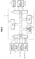
- Fig. 3 shows a hardware configuration of the control unit 9.
- the control unit 9 comprises an input section 91, a central processing unit (CPU) 92 constituted by a microcomputer, a read only memory (ROM) 93, a random access memory (RAM) 94, and an output section 95.
- the input section 91 receives operational signals from the control lever units 4a - 4f, instruction signals (setting signal and main switch signal) from the setting device 7, angle signals from the angle sensors 8a, 8b and 8c, and a laser beam input signal from the laser beam receiver 10b, and then executes A/D conversion of those signals.
- the ROM 93 is a storage medium in which a control program (described below) is stored.
- the CPU 92 executes predetermined processing of the signals taken in through the input section 91 in accordance with the control program stored in the ROM 93.
- the RAM 94 temporarily stores numerical values used in computation.
- the output section 95 produces output signals depending on processing results of the CPU 92, outputs the produced signals to the flow control valves 5a - 5f, and displays the body 1B, the laser reference surface R and the target excavating surface on the monitor 12.
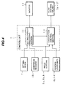
- Fig. 4 is a functional block diagram showing outline of the control program stored in the ROM 93 of the control unit 9.
- the control unit 9 comprises a setting/display processing section 11 for setting the target excavating surface and executing processing for display on the monitor 12, and an excavation control section 14 for carrying out area limiting excavation control.
- the setting/display processing section 11 receives the detection signals from the angle sensors 8a, 8b and 8c, the signal from the setting device 7 and the signal from the laser beam receiver 10b, and computes the target excavating surface and the laser reference surface based on the x-z coordinate system (described later) set for the body 1B of the hydraulic excavator, thereby setting the target excavating surface.
- the setting/display processing section 11 executes a combining process for executing coordinate transform of the target excavating surface and the laser reference surface into values on the x m -z m coordinate system (described later) that is fixedly set for an illustration of the hydraulic excavator displayed on the two-dimensional display monitor 12, and then displaying both the target excavating surface and the laser reference surface in a superimposed relation to the illustration of the hydraulic excavator. Further, the setting/display processing section 11 executes a combining process for displaying numerical values such as data representing the distance between the target excavating surface and the laser reference surface, the gradient thereof, and the distance from the laser reference surface to the bucket in the depth direction.
- the excavation control section 14 executes processing to create command signals for the flow control valves 5a - 5f so as to carry out known area limiting excavation control in accordance with the target excavating surface set by the setting/display processing section 11.
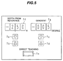
- the setting device 7 comprises, as shown in Fig. 5, operating means, e.g., switches disposed on a control panel or a grip, and indicators 7f, 7g, the switches including an up-key 7a and a down-key 7b for setting the depth from the laser reference surface R, an up-key 7c and a down-key 7d for setting the gradient, and a direct teaching button 7e.
- operating means e.g., switches disposed on a control panel or a grip
- indicators 7f, 7g the switches including an up-key 7a and a down-key 7b for setting the depth from the laser reference surface R, an up-key 7c and a down-key 7d for setting the gradient, and a direct teaching button 7e.
- the depth from the laser reference surface R can be set by operating the up-key 7a and the down-key 7b, and the setting result is indicated on the indicator 7f.
- the target excavating surface relative to the body 1B at that time is computed and set, and the bucket position relative to the laser reference surface R is computed and set as the depth from the laser reference surface.
- the gradient of the laser reference surface and the target excavating surface can be set by operating the up-key 7c or the down-key 7d, and the setting result is indicated on the indicator 7g.
- the setting device 7 outputs, to the setting/display processing section 11, a direct teaching signal, an excavating depth signal and a gradient signal, which are related to the excavating surface and entered by the operator.
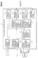
- Fig. 6 represents, in the form of a block diagram, the processing functions of the setting/display processing section 11.
- the setting/display processing section 11 includes various functions executed by a section 11a for computing bucket prong-end coordinates; a section 11b for computing the positional relationship between the body and the laser reference surface; a section 11c for storing the positional relationship (depth) between the laser reference surface and the target excavating surface; a section 11d for computing and storing the positional relationship between the body and the target excavating surface; a computing section 11e for transform of the positional relationship between the body and the laser reference surface into monitor coordinates; a computing section 11f for transform of the positional relationship between the body and the target excavating surface into monitor coordinates; a computing section 11g for producing a picture of the laser reference surface; a computing section 11h for producing a picture of the target excavating surface; a computing section 11i for display of the setting values; and a computing section 11j for producing a picture of the body.
- the section 11a for computing bucket prong-end coordinates computes, on the basis of the x-z coordinate system set for the body 1B and the dimensions of the respective components shown in Fig. 7, as well as of the detection signals from the angle sensors 8a, 8b and 8c, coordinate values (Pvx, Pvz) of the bucket prong end on the x-z coordinate system from the following formulae (1) and (2):
- Pvx LV ⁇ cos( ⁇ B + ⁇ A + ⁇ V) + LA ⁇ cos( ⁇ B + ⁇ A) + LB ⁇ cos ⁇ B + LF1
- Pvz - LV ⁇ sin( ⁇ B + ⁇ A + ⁇ V) - LA ⁇ sin( ⁇ B + ⁇ A) - LB ⁇ sin ⁇ B + LF2
- the x-z coordinate system is an orthogonal coordinate system with the origin set at a predetermined position of the body 1B of the hydraulic excavator, e.g., the center of a bottom surface of the body 1B.
- the target excavating surface is denoted by T in Fig. 7.
- the section 11b for computing the positional relationship between the body and the laser reference surface computes a linear equation of the laser reference surface R on the x-z coordinate system from both coordinate values (PLx, PLz) of the laser beam receiver 10b on the x-z coordinate system resulted when the laser beam receiver 10b receives the laser beam, and a gradient ⁇ set by the setting device 7.
- the coordinate values (PLx, PLz) of the laser beam receiver 10b on the x-z coordinate system resulted when the laser beam receiver 10b receives the laser beam is computed from the following formulae (1A) and (2A), as with the above formulae (1) and (2), based on the dimensions of the respective components and the detection signals from the angle sensors 8a, 8b:
- PLx LF ⁇ cos( ⁇ B + ⁇ A - ⁇ L) + LB ⁇ cos ⁇ B + LF1
- PLz - LF ⁇ sin( ⁇ B + ⁇ A - ⁇ L) - LB ⁇ sin ⁇ B + LF2
- the section 11c for storing the positional relationship (depth) between the laser reference surface and the target excavating surface stores a dept setting value Ld set by the setting device 7 relative to the laser reference surface R.
- the section 11d for computing and storing the positional relationship between the body and the target excavating surface computes a linear equation of the target excavating surface T on the x-z coordinate system from the following formula (4) based on both the positional relationship between the body and the laser reference surface computed by the computing section 11b and the depth setting value Ld stored in the storing section 11c.
- a coordinate plane of the x m -z m coordinate system is constituted by a two-dimensional dot matrix, and an area defined by coordinates (x m1 , z m1 ) and (x m2 , z m2 ) serves as a display region.
- an illustration 12c of the hydraulic excavator is fixedly displayed on the display section 20, and the origin Om of the x m -z m coordinate system is set at the center of the bottom surface of the hydraulic excavator represented by the illustration 12c in match with the origin O of the x-z coordinate system of the body 1B.
- the computing section 11f for transform of the positional relationship between the body and the target excavating surface into monitor coordinates transforms, as with the computing section 11e, the linear equation of the target excavating surface T, e.g., z tan ⁇ •x + (PLz - tan ⁇ •PLx) + Ld expressed by the above formula (4), into coordinate values on the x m -z m coordinate system of the display section 20 shown in Fig. 8.
- the computing section 11g for producing a picture of the laser reference surface executes processing to produce and output a picture signal for displaying the linear equation of the laser reference surface R obtained by the computing section 11e as a straight line on the x m -z m coordinate system of the display section 20.
- a straight line representing the laser reference surface R is then displayed on the display section 20 of the monitor 12 as indicated by a broken line 12a in Fig. 9.
- the computing section 11h for producing a picture of the target excavating surface executes processing to produce and output a picture signal for displaying a straight line representing the target excavating surface T obtained by the computing section 11f on the x m -z m coordinate plane of the display section 20.
- a straight line representing the target excavating surface T is then displayed on the display section 20 of the monitor 12 as indicated by a solid line 12b in Fig. 9.
- the computing section 11j for producing a picture of the hydraulic excavator body executes processing to produce a picture of the body 1B of the hydraulic excavator in the form of an illustration, and processing to produce and output a picture signal for displaying the produced illustration in a fixed position on the x m -z m coordinate plane of the display section 20 such that the center of the bottom surface of the hydraulic excavator is held in match with the origin Om.
- the illustration is then displayed on the display section 20 of the monitor 12 as indicated by 12c in Fig. 9.
- the computing section 11i for display of the setting values receives and computes data such as the gradient ⁇ of the target excavating surface T, the distance Ld between the laser reference surface R and the target excavating surface T in the depth direction, and the distance LPv from the laser reference surface R to the bucket prong end.
- the display computing section 11i executes processing to produce and output a picture signal for displaying the gradient (setting gradient) ⁇ of the target excavating surface T, the distance (setting depth) Ld between the laser reference surface R and the target excavating surface T in the depth direction, and the distance (prong end depth) LPv from the laser reference surface R to the bucket prong end as numerical values on the x m -z m coordinate plane of the display section 20.
- Those data are therefore displayed, for example, at the upper left corner in the display section 20 of the monitor 12 as indicated in Fig. 9.
- the positional relationships among the body 1B, the target excavating surface T and the laser reference surface R, and the associated numerical values are displayed on the display section 20 of the monitor 12 as indicated in Fig. 9.
- the operator operates the laser lighthouse 10a and sets the laser reference surface R parallel to the target excavating surface that is to be set.
- the operator enters and sets the depth (height) Ld from the laser reference surface R to the target excavating surface T by operating the keys 7a, 7b of the setting device 7 shown in Fig. 5.
- the storing section 11c stores the depth setting value Ld of the target excavating surface T relative to the laser reference surface R, which is set by the setting device 7.
- the operator sets the gradient ⁇ by employing the keys 7c, 7d of the setting device 7.
- the operator moves the front device 1A so that the laser beam receiver 10b attached to the arm 1b receives the laser beam.
- the computing section 11b computes, from the formula (3), the linear equation of the laser reference surface R on the x-z coordinate system of the body 1B based on both the coordinate values (PLx, PLz) of the laser beam receiver 10b on the x-z coordinate system resulted when the laser beam receiver 10b receives the laser beam, and the gradient ⁇ set by the setting device 7.
- the computing and storing section 11d computes and stores, from the formula (4), the linear equation of the target excavating surface T on the x-z coordinate system of the body 1B based on both the positional relationship between the body 1B and the laser reference surface R computed by the computing section 11b and the depth setting value Ld stored in the storing section 11c.
- the processing of the computing sections 11e - 11j is further executed.
- the body 1B, the laser reference surface R and the target excavating surface T are displayed by the illustration 12c, the broken line 12a and the solid line 12b on the display section 20 of the monitor 12, respectively.
- the gradient ⁇ of the target excavating surface T, the setting depth Ld of the target excavating surface T relative to the laser reference surface R, and the distance LPv from the laser reference surface R to the bucket prong end are displayed at the upper left corner of the display section 20.
- the operator can visually confirm and recognize the positional relationship between the body and the target excavating surface, and the positional relationship between the laser reference surface and the target excavating surface. As a result, the operator can ascertain whether the setting conditions are proper or not.
- the operator operates the front device 1A for carrying out automatic excavation along the target excavating surface T stored in the computing and storing section 11d under the area limiting excavation control.
- the body 1B is traveled as shown in Fig. 10.
- the operator moves the front device 1A so that the laser beam receiver 10b attached to the arm 1b receives the laser beam.
- the computing section 11b computes the positional relationship between the body 1B and the laser reference surface R, thereby compensating for change of the body position caused upon the travel of the body 1B.
- the computing and storing section 11d computes and stores for update, from the above formula (4), the linear equation of the target excavating surface T on the x-z coordinate system of the body 1B based on both the positional relationship between the body 1B and the laser reference surface R computed by the computing section 11b and the depth setting value Ld stored in the storing section 11c.
- the operator operates the front device 1A for carrying out automatic excavation along the target excavating surface T stored in the computing and storing section 11d under the area limiting excavation control.
- the automatic excavation is carried out along the surface having the predetermined depth and gradient relative to the laser reference surface R by employing the laser reference surface R as a reference, while the body 1B is traveled successively.
- the lines 12a, 12b representing the target excavating surface T and the laser reference surface R are displayed on the monitor 12 mounted within the cab in a superimposed relation to the illustration 12c of the body 1B. Therefore, the operator can visually recognize not only the positional relationship between the body 1B and the target excavating surface T, but also the positional relationship between the laser reference surface R and the target excavating surface T. Hence, when carrying out excavation continuously over a long distance until and along a surface at a predetermined depth, the target excavating surface T can be easily set without causing a setting error of the target excavating surface T.
- a setting/display processing section 11A according to a second embodiment of the present invention will be described below with reference to Figs. 11 and 12. These processing functions correspond to the method of inputting numerical values and to the case where transform into monitor coordinates is carried out on the basis of the target excavating surface. Note that, in Fig. 11, the same symbols as those in Fig. 6 denote the same components.
- the setting/display processing section 11A differs from the setting/display processing section 11 shown in Fig. 6 in that a computing section 11k for transform of the positional relationship between the laser reference surface and the target excavating surface into monitor coordinates; a computing section 11Af for transform of the positional relationship between the body and the target excavating surface into monitor coordinates; a computing section 11Ag for producing a picture of the laser reference surface; a computing section 11Ah for producing a picture of the target excavating surface; and a computing section 11Aj for producing a picture of the body are provided instead of the computing sections 11e - 11h and 11j in Fig. 6.
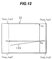
- the computing section 11k for transform of the positional relationship between the laser reference surface and the target excavating surface into monitor coordinates computes a linear equation of the laser reference surface R on an intermediate orthogonal coordinate system, in which the origin is set at a predetermined position (e.g., a cross point between an x-axis of the x-z coordinate system and the target excavating surface T) on the target excavating surface T, by using the depth setting value Ld of the target excavating surface T relative to the laser reference surface R, which has been stored in the storing section 11c. Then, the computing section 11k transforms the computed linear equation into coordinate values on the x m -z m coordinate system of the display section 20 of the monitor 12 shown in Fig. 12. In Fig.
- a line 12b representing the target excavating surface T is displayed on the display section 20, and the origin Om of the x m -z m coordinate system is fixedly set at a position on the line 12b corresponding to the above-mentioned predetermined position on the target excavating surface T.
- a manner of coordinate transform into the x m -z m coordinate system is similar to that described above in connection with the computing section 11e in the first embodiment.
- the computing section 11Af for transform of the positional relationship between the body and the target excavating surface into monitor coordinates computes a position of the body 1B on the intermediate coordinate system by using the linear equation of the target excavating surface T on the x-z coordinate system of the body 1B computed by the computing section 11d, and then transforms the computed values into coordinate values on the x m -z m coordinate system of the display section 20 shown in Fig. 12.
- the position of the body 1B is given by the position of the origin O of the x-z coordinate system.
- the computing section 11Ag for producing a picture of the laser reference surface executes processing to produce and output a picture signal for displaying the linear equation of the laser reference surface R obtained by the computing section 11k as a straight line on the x m -z m coordinate plane of the display section 20.
- the straight line representing the laser reference surface R is then displayed on the display section 20 of the monitor 12.
- the computing section 11Aj for producing a picture of the body executes processing to produce a picture of the body 1B of the hydraulic excavator in the form of an illustration, and processing to produce and output a picture signal for displaying the produced illustration in a coordinate position, which has been computed by the computing section 11Af, on the x m -z m coordinate plane of the display section 20.
- the illustration is then displayed on the display section 20 of the monitor 12
- the computing section 11Ah for producing a picture of the target excavating surface executes processing to produce and output, using the gradient ⁇ set by the setting device 7, a picture signal for a straight line having the gradient ⁇ and passing the origin Om of the x m -z m coordinate plane of the display section 20.
- the straight line representing the target excavating surface T is then displayed on the display section 20 of the monitor 12.
- This embodiment can also provide similar advantages as those in the first embodiment.
- a setting/display processing section 11B according to a third embodiment of the present invention will be described below with reference to Figs. 13 and 14. These processing functions correspond to the method of inputting numerical values and to the case where transform into monitor coordinates is carried out on the basis of the laser reference surface. Note that, in Fig. 13, the same symbols as those in Fig. 6 denote the same components.
- the setting/display processing section 11B differs from the setting/display processing section 11 shown in Fig. 6 in that a computing section 11Be for transform of the positional relationship between the body and the laser reference surface into monitor coordinates; a computing section 11Bk for transform of the positional relationship between the laser reference surface and the target excavating surface into monitor coordinates; a computing section 11Bj for producing a picture of the body; a computing section 11Bh for producing a picture of the target excavating surface; and a computing section 11Bg for producing a picture of the laser reference surface are provided instead of the computing sections 11e - 11h and 11j in Fig. 6.
- the computing section 11Be for transform of the positional relationship between the body and the laser reference surface into monitor coordinates computes a position of the body 1B on an intermediate orthogonal coordinate system, in which the origin is set at a predetermined position (e.g., a cross point between an x-axis of the x-z coordinate system and the laser reference surface R) on the laser reference surface R, by using the linear equation of the laser reference surface R on the x-z coordinate system of the body 1B computed by the computing section 11b, and then transforms the computed values into coordinate values on the x m -z m coordinate system of the display section 20 shown in Fig. 14.
- the position of the body 1B is given by the position of the origin O of the x-z coordinate system.
- a line 12a representing the laser reference surface R is displayed on the display section 20, and the origin Om of the x m -z m coordinate system is fixedly set at a position on the line 12a corresponding to the above-mentioned predetermined position on the laser reference surface R.
- a manner of coordinate transform into the x m -z m coordinate system is similar to that described above in connection with the computing section 11e in the first embodiment.
- the computing section 11Bk for transform of the positional relationship between the laser reference surface and the target excavating surface into monitor coordinates computes a linear equation of the target excavating surface T on the intermediate orthogonal coordinate system by using the depth setting value Ld of the target excavating surface T relative to the laser reference surface R, which has been stored in the storing section 11c. Then, the computing section 11Bk transforms the computed linear equation into coordinate values on the x m -z m coordinate system of the display section 20 of the monitor 12 shown in Fig. 14.
- the computing section Bj for producing a picture of the body executes processing to produce a picture of the body 1B of the hydraulic excavator in the form of an illustration, and processing to produce and output a picture signal for displaying the produced illustration in a coordinate position, which has been computed by the computing section 11Be, on the x m -z m coordinate plane of the display section 20.
- the illustration is then displayed on the display section 20 of the monitor 12
- the computing section 11Bh for producing a picture of the target excavating surface executes processing to produce and output a picture signal for displaying the linear equation of the target excavating surface T obtained by the computing section 11Bk as a straight line on the x m -z m coordinate plane of the display section 20.
- the straight line representing the target excavating surface T is then displayed on the display section 20 of the monitor 12.
- the computing section 11Bg for producing a picture of the laser reference surface executes processing to produce and output, using the gradient ⁇ set by the setting device 7, a picture signal for a straight line having the gradient ⁇ and passing the origin Om of the x m -z m coordinate plane of the display section 20.
- the straight line representing the laser reference surface R is then displayed in the display section 20 of the monitor 12.
- This embodiment can also provide similar advantages as those in the first embodiment.
- a setting/display processing section 11C according to a fourth embodiment of the present invention will be described below with reference to Figs. 7 and 15. These processing functions correspond to the direct teaching method. Note that, in Fig. 15, the same symbols as those in Fig. 6 denote the same components.
- the setting/display processing section 11C differs from the setting/display processing section 11 shown in Fig. 6 in that a section 11s for computing and storing the positional relationship between the body and the target excavating surface and a section 11t for computing and storing the positional relationship (depth) between the laser reference surface and the target excavating surface are provided instead of the section 11c for storing the positional relationship (depth) between the laser reference surface and the target excavating surface and the section 11d for computing and storing the positional relationship between the body and the target excavating surface.
- the section 11t for computing and storing the positional relationship (depth) between the laser reference surface and the target excavating surface computes and stores the distance Ld between the laser reference surface R and the target excavating surface T in the depth direction based on both the positional relationship between the body 1B and the laser reference surface R computed by the computing section 11b (i.e., the linear equation of the laser reference surface R on the x-z coordinate system, which is expressed by the above-mentioned formula (3) and has been computed from both the coordinate values (PLx, PLz) of the laser beam receiver 10b on the x-z coordinate system resulted when the laser beam receiver 10b receives the laser beam, and the gradient ⁇ set by the setting device 7), and the linear equation of the target excavating surface T, expressed by the above formula (9), on the x-z coordinate system of the body 1B, which has been stored in the computing and storing section 11s.
- the processing functions of the computing sections 11e - 11i are the same as those in the first embodiment shown in Fig. 6.
- the linear equation of the target excavating surface T is transformed into coordinate values on the x m -z m coordinate system of the monitor 12 by employing, as the linear equation of the target excavating surface T on the x-z coordinate system of the body 1B, the above-mentioned formula (9) at the initial excavating position before the travel of the body and the above-mentioned formula (4) after the travel of the body.
- the operator operates the laser lighthouse 10a and sets the laser reference surface R parallel to the target excavating surface that is to be set.
- the operator moves the front device 1A so that the prong end of the bucket 1c moves to a target point of the excavation, as indicated by two-dot-chain lines in Fig. 7, and then depresses the direct teaching key 7e shown in Fig. 5. Also, before or after this operation, the operator sets the gradient ⁇ by employing the keys 7c, 7d of the setting device 7.
- the computing section 11a computes, on the basis of the x-z coordinate system set for the body 1B and the dimensions of the respective components shown in Fig. 7, coordinate values (Pcx, Pcz) of the bucket prong end on the x-z coordinate system from the formulae (1) and (2). Further, the computing and storing section 11s computes and stores a linear equation of the target excavating surface T on the x-z coordinate system of the body 1B from the equation (9) based on both the computed coordinate values (Pcx, Pcz) of the bucket prong end on the x-z coordinate system and the gradient ⁇ of the laser reference surface.
- the operator moves the front device 1A so that the laser beam receiver 10b attached to the arm 1b receives the laser beam.
- the computing section 11b computes, from the formula (3), a linear equation of the laser reference surface R on the x-z coordinate system of the body 1B based on both the coordinate values (PLx, PLz) of the laser beam receiver 10b on the x-z coordinate system resulted when the laser beam receiver 10b receives the laser beam, and the gradient ⁇ set by the setting device 7.
- the computing and storing section 11t computes and stores, from the formula (10), the depth setting value Ld based on both the positional relationship between the body 1B and the laser reference surface R, which has been computed by the computing section 11b, and the linear equation of the target excavating surface T on the x-z coordinate system of the body 1B, which has been stored in the computing and storing section 11s.
- the processing of the computing sections 11e - 11j is further executed.
- the body 1B, the laser reference surface R and the target excavating surface T are displayed by an illustration 12c, a broken line 12a and a solid line 12b on the display section 20 of the monitor 12, respectively.
- the gradient ⁇ of the target excavating surface T, the setting depth Ld of the target excavating surface T relative to the laser reference surface R, and the distance LPv from the laser reference surface R to the bucket prong end are displayed at the upper left corner of the display section 20.
- the operator can visually confirm and recognize the positional relationship between the body and the target excavating surface, and the positional relationship between the laser reference surface and the target excavating surface. As a result, the operator can ascertain whether the setting conditions are proper or not.
- the operator operates the front device 1A for carrying out automatic excavation along the target excavating surface stored in the computing and storing section 11s under the area limiting excavation control.
- the body 1B is traveled as shown in Fig. 10.
- the operator moves the front device 1A so that the laser beam receiver 10b attached to the arm 1b receives the laser beam.
- the computing section 11b computes the positional relationship between the body 1B and the laser reference surface R, thereby compensating for change of the body position caused upon the travel of the body 1B.
- the computing and storing section 11s computes and stores for update, from the above formula (4), the linear equation of the target excavating surface T on the x-z coordinate system of the body 1B based on both the positional relationship between the body 1B and the laser reference surface R computed by the computing section 11b and the depth setting value Ld stored in the computing and storing section 11t.
- the operator operates the front device 1A for carrying out automatic excavation along the target excavating surface T stored in the computing and storing section 11s under the area limiting excavation control.
- the automatic excavation is carried out along the surface having the predetermined depth and gradient relative to the laser reference surface R by employing the laser reference surface R as a reference, while the body 1B is traveled successively.
- the processing to execute transform into monitor coordinates and then to produce and output picture signals after computing the positional relationships among the body 1B, the laser reference surface R and the target excavating surface T by the computing section 11b and the computing and storing sections 11s, 11t is assumed to be the same as the processing executed by the computing sections 11e - 11h and 11j in the first embodiment shown in Fig. 6.
- the computing sections 11e - 11h and 11j are employed in the case of transform into monitor coordinates on the basis of the body.
- transform into monitor coordinates may be executed on the basis of the target excavating surface or the laser reference surface as with the second and third embodiments.
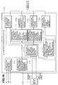
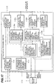
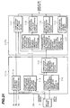
- Figs. 16 and 17 are block diagrams showing the processing functions executed by setting/display processing sections in such cases. More specifically, Fig. 16 shows, as a fifth embodiment of the present invention, the processing functions of a setting/display processing section 11D adapted for the case where transform into monitor coordinates is executed on the basis of the target excavating surface, and Fig. 17 shows, as a sixth embodiment of the present invention, the processing functions of a setting/display processing section 11E adapted for the case where transform into monitor coordinates is executed on the basis of the laser reference surface.
- the same symbols as those in Figs. 11 and 15 denote the same components.
- Fig. 17 the same symbols as those in Figs. 13 and 15 denote the same components.
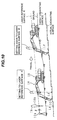
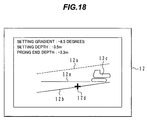
- the straight line 12a representing the laser reference surface R, the straight line 12b representing the target excavating surface T, and the illustration 12c of the body 1B of the hydraulic excavator are displayed on the display section 20 of the monitor 12.
- a current bucket end position 12d is displayed on a screen of the display section 20 in a superimposed manner for clearly indicating the positional relationship between the target excavating surface and the bucket end, and a line 12e extended along the lower travel structure of the body 1B and representing the ground is displayed as an auxiliary line on the screen of the display section 20.
- This second display example enables the operator to more precisely confirm current situations including a current position of the work implement and a relation relative to the ground.
- a third display example in the display device for the target excavating-surface setting system of the present invention will be described below with reference to Fig. 19.
- This third display example differs from the second display example of Fig. 18 in that a current position of the work implement, e.g., the bucket, is displayed in the form of an illustration 12d of the bucket. Also, by providing an inclinometer to detect a gradient of the body in the back-and-forth direction, a line 12e extended along the lower travel structure of the body 1B and representing the ground and the illustration 12a of the body 1B are displayed at an inclination depending on the detected gradient. Accordingly, this third display example enables the operator to more precisely confirm current situations including a current position of the work implement, an inclination of the body, and a ground condition.
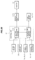
- a display processing section is separated from the setting/display processing section disposed in the control unit, and is provided as a display processing unit separate from the control unit.
- a display processing section is separated from the setting/display processing section disposed in the control unit, and is provided as a display processing unit separate from the control unit.
- members identical to those in Figs. 4 and 6 are denoted by the same symbols.
- a control unit 9F comprises a setting processing section 11Fa for setting the target excavating surface T and computing the positional relationships among the body 1B, the laser reference surface R and the target excavating surface T, and an excavation control section 14 for carrying out area limiting excavation control. Also, a display processing unit 11Fb is provided separately from the control unit 9F.
- the setting processing section 11Fa includes respective functions executed by a section 11a for computing bucket prong-end coordinates; a section 11b for computing the positional relationship between the body and the laser reference surface; a section 11c for storing the positional relationship (depth) between the laser reference surface and the target excavating surface; and a section 11d for computing and storing the positional relationship between the body and the target excavating surface.
- the display processing unit 11Fb comprises a computing section 11e for transform of the positional relationship between the body and the laser reference surface into monitor coordinates; a computing section 11f for transform of the positional relationship between the body and the target excavating surface into monitor coordinates; a computing section 11g for producing a picture of the laser reference surface; a computing section 11h for producing a picture of the target excavating surface; and a computing section 11i for display of the setting values; and a computing section 11j for producing a picture of the body.
- a monitor 12 is mounted within a cab at a corner obliquely in front of an operator seat.
- a control unit 9Fa is mounted within the cab at a position, for example, behind and below the operator seat, and the display processing unit 9b is mounted, for example, in a console box disposed laterally of the operator seat.
- This embodiment can also provide similar advantages as those in the first embodiment.
- the processing to produce and output a picture signal is executed by the dedicated processing unit 11Fb, it is easily possible for the display processing unit 11Fb to have an additional processing function to produce and output a picture signal for another information, such as information of maintenance and inspection transmitted through a communicating satellite.
- the display device is therefore adaptable for multiple purposes in use.
- the target excavating-surface setting system and the display device of the present invention are not limited in details to the embodiments described above, but may be modified in various ways.
- the laser reference surface defined by a laser beam is used as the external reference in the above-described embodiments
- any other suitable external reference e.g., a leveling string
- the positional relationship between the body and the laser reference surface may be computed by the computing section 11b by moving the front device such that the bucket prong end contacts the leveling string, depressing a trigger switch in that condition, and then employing detection values of the angle sensors 8a, 8b and 8c at that time.
- a front reference may be marked on the lateral surface of the arm by the use of a panel, painting or the like, instead of the laser beam receiver 10b.
- the positional relationship between the body and the laser reference surface can also be computed by the computing section 11b, as with the case of using a leveling string, by depressing the trigger switch at the time when a laser beam impinges upon the front reference mark.
- the excavation when carrying out excavation after setting the target excavating surface, the excavation is not limited to be performed under area limiting excavation control, but may be performed under any other suitable excavation control.
- the display example on the display device, shown in Fig. 9, 18 or 19, may be modified such that the target excavating surface and the external reference surface are drawn in different display colors and/or different line types, thus allowing the operator to more easily visually discern those surfaces.
- electrical levers are used as the control levers in the above-described embodiments, they may be replaced by hydraulic pilot levers.
- angle sensors for detecting rotational angles are employed as means for detecting the status variables relating to the position and the posture of the front device 1A, the stroke of each cylinder may be detected instead.
- a target excavating surface can be easily set using an external reference when excavation is carried out continuously over a long distance until and along a surface at a predetermined depth.
Landscapes
- Engineering & Computer Science (AREA)
- Mining & Mineral Resources (AREA)
- Civil Engineering (AREA)
- General Engineering & Computer Science (AREA)
- Structural Engineering (AREA)
- Mechanical Engineering (AREA)
- Life Sciences & Earth Sciences (AREA)
- General Life Sciences & Earth Sciences (AREA)
- Paleontology (AREA)
- Operation Control Of Excavators (AREA)
- Component Parts Of Construction Machinery (AREA)
Abstract
A setting/display processing section 11 of a control
unit 9 comprises means 11b, 11c and 11d for computing the
positional relationships among a machine body, an external
reference and a target excavating surface by using a signal
from a setting device 7 and signals supplied from angle
sensors 8a, 8b when a front device is in a predetermined
positional relationship relative to a laser reference
surface, and means 11e, 11f, llg, 11h and 11j for executing
picture processing by using the computed positional
relationships, and then producing and outputting picture
signals to display the positional relationships among the
body, the external reference and the target excavating
surface. A display device 12 displays an illustration of
the body and lines representing respectively the external
reference and the target excavating surface on a display
section 20 in accordance with the computed positional
relationships. As a result, when carrying out excavation
continuously over a long distance along a surface at a
predetermined depth, a target excavating surface can be
easily set using an external reference and a setting error
relative to the external reference is less apt to occur.
Description
The present invention relates to a target excavating-surface
setting system for an excavating machine, such as a
hydraulic excavator, which is employed to set work
conditions of the excavating machine, a storage medium
storing a target excavating-surface setting program for an
excavating machine, and a display device for use in the
target excavating-surface setting system.
In a hydraulic excavator, an operator operates front
members, such as a boom, by associated manual control
levers. There is however a difficulty for the operator to
judge whether or not excavation is carried out precisely
along a ditch at a predetermined depth or a slope at a
predetermined gradient, just by visually observing the front
operation. It is therefore known to set the depth of an
excavating surface or the gradient of a slope beforehand,
and to perform automatic excavation control so that the set
depth or gradient is achieved. A target excavating surface
must be set to perform the automatic excavation control. A
monitoring apparatus for an excavating machine disclosed in
JP,A 62-185932 and an excavating machine disclosed in JP,A
5-287782 are proposed as employing a two-dimensional display
device for setting a target excavating surface.
In the excavating machines disclosed in JP,A 62-185932
and JP,A 5-287782, a machine body and a target excavating
surface are displayed in the form of pictures on a monitor,
and a depth from the machine body to the target excavating
surface or a gradient of the target excavating surface is
also displayed on the monitor.
Further, an excavation area setting system for area
limiting excavation control in construction machines,
disclosed in, e.g., JP,A 9-53253, proposes a system in which
an external reference, such as a leveling string or a laser
reference surface formed by a laser lighthouse installed
outside a machine body, is used in combination with a
hydraulic excavator, and excavation is carried out
continuously over a long distance along a surface at a
certain depth or gradient relative to the external
reference.
In the excavation area setting system disclosed in JP,A
9-53253, a laser beam receiver is attached to a front
member, and a vertical shift upon travel of the machine body
is compensated for with the aid of a laser beam so that a
continuous linear excavating surface is obtained. Also, in
that excavation area setting system, the relationship
between the machine body and a target excavating surface is
set by setting the target excavating surface relative to the
laser reference surface.
In the excavating machines disclosed in JP,A 62-185932
and JP,A 5-287782, however, any external reference is not
used. This means that display of an external reference is
neither provided nor intended.
Also, the excavation area setting system disclosed in
JP,A 9-53253 has a problem that a setting error is apt to
occur because the depth, set by a setting device, from the
laser reference surface (external reference) to the target
excavating surface is displayed just in the form of a
numerical value on the monitor.
More specifically, in a system employing a laser
reference surface (external reference), excavation is
carried out continuously over a long distance along a
surface at a predetermined depth from the external reference
such as the laser reference surface and, to this end,
setting of a target excavating surface must be repeated
using the external reference. In order to realize precise
setting, therefore, it is required that the operator can
confirm and recognize not only the positional relationship
between a machine body and the target excavating surface,
but also the positional relationship between the laser
reference surface and the target excavating surface. In the
conventional system wherein only a numerical value or only
the positional relationship between the machine body and the
target excavating surface is displayed, it is difficult for
the operator to visually recognize the positional
relationship between the laser reference surface and the
target excavating surface, and hence a setting error is apt
to occur.
An object of the present invention is to provide a
target excavating-surface setting system for an excavating
machine, which can easily set a target excavating surface
using an external reference when excavation is carried out
continuously over a long distance along a surface at a
predetermined depth, and which is less apt to cause a
setting error relative to the external reference, as well as
to a storage medium and a display device for use in the
target excavating-surface setting system.
Embodiments of the present invention will be described
below with reference to the drawings.
Figs. 1 to 10 show a target excavating-surface setting
system for an excavating machine according to a first
embodiment of the present invention, including a display
device for use therein. This embodiment represents the case
where the present invention is applied to a hydraulic
excavator.
In Fig. 1, the hydraulic excavator comprises a
hydraulic pump 2; a plurality of hydraulic actuators
including a boom cylinder 3a, an arm cylinder 3b, a bucket
cylinder 3c, a swing motor 3d and left and right travel
motors 3e, 3f, which are driven by a hydraulic fluid from
the hydraulic pump 2; a plurality of control lever units 4a
- 4f provided respectively corresponding to the hydraulic
actuators 3a - 3f; a plurality of flow control valves 5a -
5f controlled by the plurality of control lever units 4a -
4f and controlling respective flow rates of the hydraulic
fluid supplied to the hydraulic actuators 3a - 3f; a relief
valve 6 which is opened when the delivery pressure of the
hydraulic pump 2 exceeds a preset value; and a control unit
9 for receiving operational signals from the control lever
units 4a - 4f and controlling the flow control valves 5a -
5f. These components constitute a hydraulic drive system
for driving driven members of the hydraulic excavator.
In this embodiment, the control lever units 4a - 4f are
electrical lever units for outputting electrical signals as
the operational signals, and the flow control valves 5a - 5f
are electro-hydraulic converting means for converting the
electrical signals into pilot pressures, e.g., electrically
or hydraulically operated valves each having proportional
solenoid valves provided at opposite ends. The control unit
9 receives the operational signals from the control lever
units 4a - 4f and produces flow-control-valve driving
signals corresponding to the received signals, thereby
driving and controlling the flow control valves 5a - 5f.
As shown in Fig. 2, the hydraulic excavator is made up
of a multi-articulated front device 1A comprising a boom 1a,
an arm 1b and a bucket (work implement) 1c which are each
rotatable in the vertical direction, and a machine body 1B
comprising an upper swing structure 1d and a lower travel
structure 1e. The boom 1a of the front device 1A is
supported at its base end to a front portion of the upper
swing structure 1d.
The boom 1a, the arm 1b, the bucket 1c, the upper swing
structure 1d, and the lower travel structure 1e, shown in
Fig. 2, are driven respectively by the boom cylinder 3a, the
arm cylinder 3b, the bucket cylinder 3c, the swing motor 3d,
and the left and right travel motors 3e, 3f shown in Fig. 1.
The operations of these members are instructed by the
control lever units 4a - 4f.
The target excavating-surface setting system according
to this embodiment is installed in the hydraulic excavator
constructed as described above. The target excavating-surface
setting system comprises a setting device 7 used for
setting a target excavating surface that should be linearly
finished; angle sensors 8a, 8b and 8c provided at pivots
about which the boom 1a, the arm 1b and the bucket 1c are
rotated, respectively, and detecting rotational angles of
the boom 1a, the arm 1b and the bucket 1c as status
variables relating to the position and the posture of the
front device 1A; a laser beam receiver 10b attached to a
lateral surface of the arm 1b and receiving a laser beam
formed by the laser lighthouse 10a installed outside the
body; a two-dimensional display monitor (display device) 12
mounted within a cab at a corner obliquely in front of an
operator seat; and later-described processing functions
incorporated in the control unit 9. The laser beam formed
by the laser lighthouse 10a provides a laser reference
surface (external reference) R.
Fig. 3 shows a hardware configuration of the control
unit 9. The control unit 9 comprises an input section 91, a
central processing unit (CPU) 92 constituted by a
microcomputer, a read only memory (ROM) 93, a random access
memory (RAM) 94, and an output section 95. The input
section 91 receives operational signals from the control
lever units 4a - 4f, instruction signals (setting signal and
main switch signal) from the setting device 7, angle signals
from the angle sensors 8a, 8b and 8c, and a laser beam input
signal from the laser beam receiver 10b, and then executes
A/D conversion of those signals. The ROM 93 is a storage
medium in which a control program (described below) is
stored. The CPU 92 executes predetermined processing of the
signals taken in through the input section 91 in accordance
with the control program stored in the ROM 93. The RAM 94
temporarily stores numerical values used in computation.
The output section 95 produces output signals depending on
processing results of the CPU 92, outputs the produced
signals to the flow control valves 5a - 5f, and displays the
body 1B, the laser reference surface R and the target
excavating surface on the monitor 12.
Fig. 4 is a functional block diagram showing outline of
the control program stored in the ROM 93 of the control unit
9. The control unit 9 comprises a setting/display
processing section 11 for setting the target excavating
surface and executing processing for display on the monitor
12, and an excavation control section 14 for carrying out
area limiting excavation control.
The setting/display processing section 11 receives the
detection signals from the angle sensors 8a, 8b and 8c, the
signal from the setting device 7 and the signal from the
laser beam receiver 10b, and computes the target excavating
surface and the laser reference surface based on the x-z
coordinate system (described later) set for the body 1B of
the hydraulic excavator, thereby setting the target
excavating surface. Also, the setting/display processing
section 11 executes a combining process for executing
coordinate transform of the target excavating surface and
the laser reference surface into values on the xm-zm
coordinate system (described later) that is fixedly set for
an illustration of the hydraulic excavator displayed on the
two-dimensional display monitor 12, and then displaying both
the target excavating surface and the laser reference
surface in a superimposed relation to the illustration of
the hydraulic excavator. Further, the setting/display
processing section 11 executes a combining process for
displaying numerical values such as data representing the
distance between the target excavating surface and the laser
reference surface, the gradient thereof, and the distance
from the laser reference surface to the bucket in the depth
direction.
The excavation control section 14 executes processing
to create command signals for the flow control valves 5a -
5f so as to carry out known area limiting excavation control
in accordance with the target excavating surface set by the
setting/display processing section 11.
The setting device 7 comprises, as shown in Fig. 5,
operating means, e.g., switches disposed on a control panel
or a grip, and indicators 7f, 7g, the switches including an
up-key 7a and a down-key 7b for setting the depth from the
laser reference surface R, an up-key 7c and a down-key 7d
for setting the gradient, and a direct teaching button 7e.
In the case of using a method of inputting numerical values,
the depth from the laser reference surface R can be set by
operating the up-key 7a and the down-key 7b, and the setting
result is indicated on the indicator 7f. In the case of
using a direct teaching method, when the direct teaching
button 7e is operated, the target excavating surface
relative to the body 1B at that time is computed and set,
and the bucket position relative to the laser reference
surface R is computed and set as the depth from the laser
reference surface. Also, in either case, the gradient of
the laser reference surface and the target excavating
surface can be set by operating the up-key 7c or the down-key
7d, and the setting result is indicated on the indicator
7g. The setting device 7 outputs, to the setting/display
processing section 11, a direct teaching signal, an
excavating depth signal and a gradient signal, which are
related to the excavating surface and entered by the
operator.
The processing functions of the setting/display
processing section 11 will now be described with reference
to Fig. 6. These processing functions correspond to the
method of inputting numerical values and to the case where
transform into monitor coordinates is carried out on the
basis of the body 1B of the hydraulic excavator.
Fig. 6 represents, in the form of a block diagram, the
processing functions of the setting/display processing
section 11. The setting/display processing section 11
includes various functions executed by a section 11a for
computing bucket prong-end coordinates; a section 11b for
computing the positional relationship between the body and
the laser reference surface; a section 11c for storing the
positional relationship (depth) between the laser reference
surface and the target excavating surface; a section 11d for
computing and storing the positional relationship between
the body and the target excavating surface; a computing
section 11e for transform of the positional relationship
between the body and the laser reference surface into
monitor coordinates; a computing section 11f for transform
of the positional relationship between the body and the
target excavating surface into monitor coordinates; a
computing section 11g for producing a picture of the laser
reference surface; a computing section 11h for producing a
picture of the target excavating surface; a computing
section 11i for display of the setting values; and a
computing section 11j for producing a picture of the body.
The section 11a for computing bucket prong-end
coordinates computes, on the basis of the x-z coordinate
system set for the body 1B and the dimensions of the
respective components shown in Fig. 7, as well as of the
detection signals from the angle sensors 8a, 8b and 8c,
coordinate values (Pvx, Pvz) of the bucket prong end on the
x-z coordinate system from the following formulae (1) and
(2):
Pvx = LV × cos(αB + αA + αV) + LA × cos(αB + αA)
+ LB × cosαB + LF1
Pvz = - LV × sin(αB + αA + αV) - LA × sin(αB + αA)
- LB × sinαB + LF2
- LV:
- bucket length (distance between bucket rotation center and bucket prong end)
- LA:
- arm length (distance between arm rotation center and bucket rotation center)
- LB:
- boom length (distance between boom rotation center and arm rotation center)
- LF1:
- x-coordinate value of boom rotation center on x-z coordinate system
- LF2:
- z-coordinate value of boom rotation center on x-z coordinate system
- αB:
- boom rotational angle
- αA:
- arm rotational angle
- αV:
- bucket rotational angle
Herein, the x-z coordinate system is an orthogonal
coordinate system with the origin set at a predetermined
position of the body 1B of the hydraulic excavator, e.g.,
the center of a bottom surface of the body 1B. Also, the
target excavating surface is denoted by T in Fig. 7.
The section 11b for computing the positional
relationship between the body and the laser reference
surface computes a linear equation of the laser reference
surface R on the x-z coordinate system from both coordinate
values (PLx, PLz) of the laser beam receiver 10b on the x-z
coordinate system resulted when the laser beam receiver 10b
receives the laser beam, and a gradient β set by the setting
device 7.
Herein, the coordinate values (PLx, PLz) of the laser
beam receiver 10b on the x-z coordinate system resulted when
the laser beam receiver 10b receives the laser beam is
computed from the following formulae (1A) and (2A), as with
the above formulae (1) and (2), based on the dimensions of
the respective components and the detection signals from the
angle sensors 8a, 8b:
PLx = LF × cos(αB + αA - αL) + LB × cosαB + LF1
PLz = - LF × sin(αB + αA - αL) - LB × sinαB + LF2
- LF:
- distance between arm rotation center and
laser beam receiver 10b - αL:
- attachment angle of laser beam receiver relative to straight line connecting arm rotation center and bucket rotation center
Also, since a linear equation of the laser reference
surface R on the x-z coordinate system is represented by a
straight line passing the coordinate values (PLx, PLz) and
having the gradient β, it is expressed by the following
formula (3):
z = tanβ•x + (PLz - tanβ•PLx)
The section 11c for storing the positional relationship
(depth) between the laser reference surface and the target
excavating surface stores a dept setting value Ld set by the
setting device 7 relative to the laser reference surface R.
The section 11d for computing and storing the
positional relationship between the body and the target
excavating surface computes a linear equation of the target
excavating surface T on the x-z coordinate system from the
following formula (4) based on both the positional
relationship between the body and the laser reference
surface computed by the computing section 11b and the depth
setting value Ld stored in the storing section 11c.
Assuming, for example, that the linear equation of the laser
reference surface R is expressed by z = tanβ•x + (PLz -
tanβ•PLx) and the depth setting value is Ld, the linear
equation of the target excavating surface T is expressed by:
z = tanβ•x + (PLz - tanβ•PLx) + Ld
The computing section 11e for transform of the
positional relationship between the body and the laser
reference surface into monitor coordinates transforms the
linear equation of the laser reference surface R, e.g., z =
tanβ•x + (PLz - tanβ•PLx), into coordinate values on the xm-zm
coordinate system set for a display section 20 of the
monitor 12 shown in Fig. 8. In Fig. 8, a coordinate plane
of the xm-zm coordinate system is constituted by a two-dimensional
dot matrix, and an area defined by coordinates
(xm1, zm1) and (xm2, zm2) serves as a display region. Also, an
illustration 12c of the hydraulic excavator is fixedly
displayed on the display section 20, and the origin Om of
the xm-zm coordinate system is set at the center of the
bottom surface of the hydraulic excavator represented by the
illustration 12c in match with the origin O of the x-z
coordinate system of the body 1B.
Assuming herein that xm1 corresponds to x1 on the x-z
coordinate system, a scale K is given by K = xm1/x1. The
linear equation z = tanβ•x + (PLz - tanβ•PLx) of the laser
reference surface is therefore expressed by the following
formula on the xm-zm coordinate system:
zm = tanβ•xm + (PLz - tanβ•PLx) × K
The computing section 11f for transform of the
positional relationship between the body and the target
excavating surface into monitor coordinates transforms, as
with the computing section 11e, the linear equation of the
target excavating surface T, e.g., z = tanβ•x + (PLz -
tanβ•PLx) + Ld expressed by the above formula (4), into
coordinate values on the xm-zm coordinate system of the
display section 20 shown in Fig. 8. Assuming a scale K =
xm1/x1 also in this case as with the computing section 11e,
the linear equation of the target excavating surface T is
expressed by the following formula on the xm-zm coordinate
system:
zm = tanβ•xm + {(PLz - tanβ•PLx) + Ld} × K
The computing section 11g for producing a picture of
the laser reference surface executes processing to produce
and output a picture signal for displaying the linear
equation of the laser reference surface R obtained by the
computing section 11e as a straight line on the xm-zm
coordinate system of the display section 20. A straight
line representing the laser reference surface R is then
displayed on the display section 20 of the monitor 12 as
indicated by a broken line 12a in Fig. 9.
The computing section 11h for producing a picture of
the target excavating surface executes processing to produce
and output a picture signal for displaying a straight line
representing the target excavating surface T obtained by the
computing section 11f on the xm-zm coordinate plane of the
display section 20. A straight line representing the target
excavating surface T is then displayed on the display
section 20 of the monitor 12 as indicated by a solid line
12b in Fig. 9.
The computing section 11j for producing a picture of
the hydraulic excavator body executes processing to produce
a picture of the body 1B of the hydraulic excavator in the
form of an illustration, and processing to produce and
output a picture signal for displaying the produced
illustration in a fixed position on the xm-zm coordinate
plane of the display section 20 such that the center of the
bottom surface of the hydraulic excavator is held in match
with the origin Om. The illustration is then displayed on
the display section 20 of the monitor 12 as indicated by 12c
in Fig. 9.
The computing section 11i for display of the setting
values receives and computes data such as the gradient β of
the target excavating surface T, the distance Ld between the
laser reference surface R and the target excavating surface
T in the depth direction, and the distance LPv from the
laser reference surface R to the bucket prong end. Herein,
the distance LPv is computed by the following formula (8):
LPv = Pvz - tanβ•Pvx - (PLz - tanβ•PLx)
Further, the display computing section 11i executes
processing to produce and output a picture signal for
displaying the gradient (setting gradient) β of the target
excavating surface T, the distance (setting depth) Ld
between the laser reference surface R and the target
excavating surface T in the depth direction, and the
distance (prong end depth) LPv from the laser reference
surface R to the bucket prong end as numerical values on the
xm-zm coordinate plane of the display section 20. Those data
are therefore displayed, for example, at the upper left
corner in the display section 20 of the monitor 12 as
indicated in Fig. 9.
As described above, the positional relationships among
the body 1B, the target excavating surface T and the laser
reference surface R, and the associated numerical values are
displayed on the display section 20 of the monitor 12 as
indicated in Fig. 9.
Procedures for setting the target excavating surface
based on the method of inputting numerical values according
to this embodiment and operating procedures for continuously
carrying out excavation along a surface at the predetermined
depth and gradient from the laser reference surface
(external reference) R in accordance with the set target
excavating surface will be described below with reference to
Figs. 6 and 10.
A description is first made of works for setting the
target excavating surface at an excavating start position
and carrying out excavation.
First, as shown in Fig. 10, the operator operates the
laser lighthouse 10a and sets the laser reference surface R
parallel to the target excavating surface that is to be set.
Then, the operator enters and sets the depth (height)
Ld from the laser reference surface R to the target
excavating surface T by operating the keys 7a, 7b of the
setting device 7 shown in Fig. 5. With this setting
operation, the storing section 11c stores the depth setting
value Ld of the target excavating surface T relative to the
laser reference surface R, which is set by the setting
device 7. Further, the operator sets the gradient β by
employing the keys 7c, 7d of the setting device 7.
Then, as shown in Fig. 10, the operator moves the front
device 1A so that the laser beam receiver 10b attached to
the arm 1b receives the laser beam. With this setting
operation, the computing section 11b computes, from the
formula (3), the linear equation of the laser reference
surface R on the x-z coordinate system of the body 1B based
on both the coordinate values (PLx, PLz) of the laser beam
receiver 10b on the x-z coordinate system resulted when the
laser beam receiver 10b receives the laser beam, and the
gradient β set by the setting device 7. Also, the computing
and storing section 11d computes and stores, from the
formula (4), the linear equation of the target excavating
surface T on the x-z coordinate system of the body 1B based
on both the positional relationship between the body 1B and
the laser reference surface R computed by the computing
section 11b and the depth setting value Ld stored in the
storing section 11c.
Incidentally, the operation of the procedure 2 and the
operation of the procedure 3 until computing the linear
equation of the laser reference surface R may be reversed
such that the procedure 2 follows the procedure 3.
Based on results of the operation setting in the
procedure 2 and the procedure 3, the processing of the
computing sections 11e - 11j is further executed. Thereby,
as shown in Fig. 9, the body 1B, the laser reference surface
R and the target excavating surface T are displayed by the
illustration 12c, the broken line 12a and the solid line 12b
on the display section 20 of the monitor 12, respectively.
At the same time, the gradient β of the target excavating
surface T, the setting depth Ld of the target excavating
surface T relative to the laser reference surface R, and the
distance LPv from the laser reference surface R to the
bucket prong end are displayed at the upper left corner of
the display section 20.
By looking at the display on the monitor 12, the
operator can visually confirm and recognize the positional
relationship between the body and the target excavating
surface, and the positional relationship between the laser
reference surface and the target excavating surface. As a
result, the operator can ascertain whether the setting
conditions are proper or not.
The operator operates the front device 1A for carrying
out automatic excavation along the target excavating surface
T stored in the computing and storing section 11d under the
area limiting excavation control.
After the excavation for the target excavating surface
over a predetermined region is completed, the body 1B is
traveled as shown in Fig. 10.
A description is next made of works for setting the
target excavating surface and carrying out excavation after
the travel of the body 1B.
After the travel of the body, as shown in Fig. 10, the
operator moves the front device 1A so that the laser beam
receiver 10b attached to the arm 1b receives the laser beam.
With this operation, the computing section 11b computes the
positional relationship between the body 1B and the laser
reference surface R, thereby compensating for change of the
body position caused upon the travel of the body 1B.
Herein, since the depth setting value Ld relative to
the laser reference surface, which has been set by the
setting device 7 at the initial setting and stored in the
storing section 11c, is not changed, the computing and
storing section 11d computes and stores for update, from the
above formula (4), the linear equation of the target
excavating surface T on the x-z coordinate system of the
body 1B based on both the positional relationship between
the body 1B and the laser reference surface R computed by
the computing section 11b and the depth setting value Ld
stored in the storing section 11c. With this processing,
also after the body 1B has traveled, change in position of
the body 1B relative to the laser reference surface R caused
upon the travel of the body 1B can be compensated for, and
the area limiting excavation control can be continuously
performed for the target excavating surface T that is in the
predetermined positional relationship relative to the laser
reference surface R.
The operator operates the front device 1A for carrying
out automatic excavation along the target excavating surface
T stored in the computing and storing section 11d under the
area limiting excavation control.
Subsequently, by repeating the procedures 6 to 8, the
automatic excavation is carried out along the surface having
the predetermined depth and gradient relative to the laser
reference surface R by employing the laser reference surface
R as a reference, while the body 1B is traveled
successively.
According to this embodiment having the above-described
construction, since the lines 12a, 12b representing the
target excavating surface T and the laser reference surface
R are displayed on the monitor 12 mounted within the cab in
a superimposed relation to the illustration 12c of the body
1B. Therefore, the operator can visually recognize not only
the positional relationship between the body 1B and the
target excavating surface T, but also the positional
relationship between the laser reference surface R and the
target excavating surface T. Hence, when carrying out
excavation continuously over a long distance until and along
a surface at a predetermined depth, the target excavating
surface T can be easily set without causing a setting error
of the target excavating surface T.
Furthermore, since data of the distance between the
external reference surface R and the target excavating
surface T and the gradient thereof, the distance between the
work implement and the laser reference surface R, etc. are
displayed in the form of numerical values, the positional
relationships among the body 1B, the target excavating
surface T and the laser reference surface R can be displayed
to the operator in an easily recognizable manner, and a
setting error of the target excavating surface T can be
avoided with higher certainty.
The processing functions of a setting/display
processing section 11A according to a second embodiment of
the present invention will be described below with reference
to Figs. 11 and 12. These processing functions correspond
to the method of inputting numerical values and to the case
where transform into monitor coordinates is carried out on
the basis of the target excavating surface. Note that, in
Fig. 11, the same symbols as those in Fig. 6 denote the same
components.
The construction of a hydraulic excavator according to
this embodiment is the same as that shown in Figs. 1 and 2,
and the hardware configuration of a control unit according
to this embodiment is the same as that shown in Fig. 3.
In Fig. 11, the setting/display processing section 11A
differs from the setting/display processing section 11 shown
in Fig. 6 in that a computing section 11k for transform of
the positional relationship between the laser reference
surface and the target excavating surface into monitor
coordinates; a computing section 11Af for transform of the
positional relationship between the body and the target
excavating surface into monitor coordinates; a computing
section 11Ag for producing a picture of the laser reference
surface; a computing section 11Ah for producing a picture of
the target excavating surface; and a computing section 11Aj
for producing a picture of the body are provided instead of
the computing sections 11e - 11h and 11j in Fig. 6.
The computing section 11k for transform of the
positional relationship between the laser reference surface
and the target excavating surface into monitor coordinates
computes a linear equation of the laser reference surface R
on an intermediate orthogonal coordinate system, in which
the origin is set at a predetermined position (e.g., a cross
point between an x-axis of the x-z coordinate system and the
target excavating surface T) on the target excavating
surface T, by using the depth setting value Ld of the target
excavating surface T relative to the laser reference surface
R, which has been stored in the storing section 11c. Then,
the computing section 11k transforms the computed linear
equation into coordinate values on the xm-zm coordinate
system of the display section 20 of the monitor 12 shown in
Fig. 12. In Fig. 12, a line 12b representing the target
excavating surface T is displayed on the display section 20,
and the origin Om of the xm-zm coordinate system is fixedly
set at a position on the line 12b corresponding to the
above-mentioned predetermined position on the target
excavating surface T. A manner of coordinate transform into
the xm-zm coordinate system is similar to that described
above in connection with the computing section 11e in the
first embodiment.
The computing section 11Af for transform of the
positional relationship between the body and the target
excavating surface into monitor coordinates computes a
position of the body 1B on the intermediate coordinate
system by using the linear equation of the target excavating
surface T on the x-z coordinate system of the body 1B
computed by the computing section 11d, and then transforms
the computed values into coordinate values on the xm-zm
coordinate system of the display section 20 shown in Fig.
12. The position of the body 1B is given by the position of
the origin O of the x-z coordinate system.
The computing section 11Ag for producing a picture of
the laser reference surface executes processing to produce
and output a picture signal for displaying the linear
equation of the laser reference surface R obtained by the
computing section 11k as a straight line on the xm-zm
coordinate plane of the display section 20. The straight
line representing the laser reference surface R is then
displayed on the display section 20 of the monitor 12.
The computing section 11Aj for producing a picture of
the body executes processing to produce a picture of the
body 1B of the hydraulic excavator in the form of an
illustration, and processing to produce and output a picture
signal for displaying the produced illustration in a
coordinate position, which has been computed by the
computing section 11Af, on the xm-zm coordinate plane of the
display section 20. The illustration is then displayed on
the display section 20 of the monitor 12
The computing section 11Ah for producing a picture of
the target excavating surface executes processing to produce
and output, using the gradient β set by the setting device
7, a picture signal for a straight line having the gradient
β and passing the origin Om of the xm-zm coordinate plane of
the display section 20. The straight line representing the
target excavating surface T is then displayed on the display
section 20 of the monitor 12.
As a result of the processing described above, the
positional relationships among the body 1B, the target
excavating surface T and the laser reference surface R are
displayed on the display section 20 of the monitor 12 as
shown in Fig. 9.
This embodiment can also provide similar advantages as
those in the first embodiment.
The processing functions of a setting/display
processing section 11B according to a third embodiment of
the present invention will be described below with reference
to Figs. 13 and 14. These processing functions correspond
to the method of inputting numerical values and to the case
where transform into monitor coordinates is carried out on
the basis of the laser reference surface. Note that, in
Fig. 13, the same symbols as those in Fig. 6 denote the same
components.
The construction of a hydraulic excavator according to
this embodiment is the same as that shown in Figs. 1 and 2,
and the hardware configuration of a control unit according
to this embodiment is the same as that shown in Fig. 3.
In Fig. 13, the setting/display processing section 11B
differs from the setting/display processing section 11 shown
in Fig. 6 in that a computing section 11Be for transform of
the positional relationship between the body and the laser
reference surface into monitor coordinates; a computing
section 11Bk for transform of the positional relationship
between the laser reference surface and the target
excavating surface into monitor coordinates; a computing
section 11Bj for producing a picture of the body; a
computing section 11Bh for producing a picture of the target
excavating surface; and a computing section 11Bg for
producing a picture of the laser reference surface are
provided instead of the computing sections 11e - 11h and 11j
in Fig. 6.
The computing section 11Be for transform of the
positional relationship between the body and the laser
reference surface into monitor coordinates computes a
position of the body 1B on an intermediate orthogonal
coordinate system, in which the origin is set at a
predetermined position (e.g., a cross point between an x-axis
of the x-z coordinate system and the laser reference
surface R) on the laser reference surface R, by using the
linear equation of the laser reference surface R on the x-z
coordinate system of the body 1B computed by the computing
section 11b, and then transforms the computed values into
coordinate values on the xm-zm coordinate system of the
display section 20 shown in Fig. 14. The position of the
body 1B is given by the position of the origin O of the x-z
coordinate system. Further, in Fig. 14, a line 12a
representing the laser reference surface R is displayed on
the display section 20, and the origin Om of the xm-zm
coordinate system is fixedly set at a position on the line
12a corresponding to the above-mentioned predetermined
position on the laser reference surface R. A manner of
coordinate transform into the xm-zm coordinate system is
similar to that described above in connection with the
computing section 11e in the first embodiment.
The computing section 11Bk for transform of the
positional relationship between the laser reference surface
and the target excavating surface into monitor coordinates
computes a linear equation of the target excavating surface
T on the intermediate orthogonal coordinate system by using
the depth setting value Ld of the target excavating surface
T relative to the laser reference surface R, which has been
stored in the storing section 11c. Then, the computing
section 11Bk transforms the computed linear equation into
coordinate values on the xm-zm coordinate system of the
display section 20 of the monitor 12 shown in Fig. 14.
The computing section Bj for producing a picture of the
body executes processing to produce a picture of the body 1B
of the hydraulic excavator in the form of an illustration,
and processing to produce and output a picture signal for
displaying the produced illustration in a coordinate
position, which has been computed by the computing section
11Be, on the xm-zm coordinate plane of the display section
20. The illustration is then displayed on the display
section 20 of the monitor 12
The computing section 11Bh for producing a picture of
the target excavating surface executes processing to produce
and output a picture signal for displaying the linear
equation of the target excavating surface T obtained by the
computing section 11Bk as a straight line on the xm-zm
coordinate plane of the display section 20. The straight
line representing the target excavating surface T is then
displayed on the display section 20 of the monitor 12.
The computing section 11Bg for producing a picture of
the laser reference surface executes processing to produce
and output, using the gradient β set by the setting device
7, a picture signal for a straight line having the gradient
β and passing the origin Om of the xm-zm coordinate plane of
the display section 20. The straight line representing the
laser reference surface R is then displayed in the display
section 20 of the monitor 12.
As a result of the processing described above, the
positional relationships among the body 1B, the target
excavating surface T and the laser reference surface R are
displayed on the display section 20 of the monitor 12. as
shown in Fig. 9.
This embodiment can also provide similar advantages as
those in the first embodiment.
The processing functions of a setting/display
processing section 11C according to a fourth embodiment of
the present invention will be described below with reference
to Figs. 7 and 15. These processing functions correspond to
the direct teaching method. Note that, in Fig. 15, the same
symbols as those in Fig. 6 denote the same components.
The construction of a hydraulic excavator according to
this embodiment is the same as that shown in Figs. 1 and 2,
and the hardware configuration of a control unit according
to this embodiment is the same as that shown in Fig. 3.
In Fig. 15, the setting/display processing section 11C
differs from the setting/display processing section 11 shown
in Fig. 6 in that a section 11s for computing and storing
the positional relationship between the body and the target
excavating surface and a section 11t for computing and
storing the positional relationship (depth) between the
laser reference surface and the target excavating surface
are provided instead of the section 11c for storing the
positional relationship (depth) between the laser reference
surface and the target excavating surface and the section
11d for computing and storing the positional relationship
between the body and the target excavating surface.
The section 11s for computing and storing the
positional relationship between and the target excavating
surface computes and stores a linear equation of the target
excavating surface T on the x-z coordinate system of the
body 1B from the following formula (9) based on both
coordinate values (Pcx, Pcz) of the bucket prong end on the
x-z coordinate system, which has been computed by the
section 11a for computing bucket prong-end coordinates upon
inputting of the direct teaching signal from the setting
device 7, and the gradient β set by the setting device 7:
z = tanβ•x + (Pcz - tanβ•Pcx)
The section 11t for computing and storing the
positional relationship (depth) between the laser reference
surface and the target excavating surface computes and
stores the distance Ld between the laser reference surface R
and the target excavating surface T in the depth direction
based on both the positional relationship between the body
1B and the laser reference surface R computed by the
computing section 11b (i.e., the linear equation of the
laser reference surface R on the x-z coordinate system,
which is expressed by the above-mentioned formula (3) and
has been computed from both the coordinate values (PLx, PLz)
of the laser beam receiver 10b on the x-z coordinate system
resulted when the laser beam receiver 10b receives the laser
beam, and the gradient β set by the setting device 7), and
the linear equation of the target excavating surface T,
expressed by the above formula (9), on the x-z coordinate
system of the body 1B, which has been stored in the
computing and storing section 11s. Herein, a formula for
computing the distance Ld in the depth direction is
expressed by the following one (10):
Ld = (segment of linear equation of target excavating
surface) - (segment of linear equation of laser
reference surface)
Further, broken lines in Fig. 15 represent a flow of
the processing after travel of the body. Specifically,
after the travel of the body, based on both the linear
equation (above-mentioned formula (3)) of the laser
reference surface R on the x-z coordinate system of the body
1B, which has been computed by the computing section 11b,
and the distance Ld between the laser reference surface R
and the target excavating surface T in the depth direction,
which has been stored in the computing and storing section
11t, the linear equation of the target excavating surface T
on the x-z coordinate system of the body 1B is computed from
the above-mentioned formula (4):
z = tanβ•x + (PLz - tanβ•PLx) + Ld
The processing functions of the computing sections 11e
- 11i are the same as those in the first embodiment shown in
Fig. 6. In the computing section 11f, however, the linear
equation of the target excavating surface T is transformed
into coordinate values on the xm-zm coordinate system of the
monitor 12 by employing, as the linear equation of the
target excavating surface T on the x-z coordinate system of
the body 1B, the above-mentioned formula (9) at the initial
excavating position before the travel of the body and the
above-mentioned formula (4) after the travel of the body.
As a result of the processing described above, the
positional relationships among the body, and the target
excavating surface and the laser reference surface, and the
associated numerical values are displayed on the monitor 12
as shown in Fig. 9.
Procedures for setting the target excavating surface
based on the direct teaching method according to this
embodiment and processing procedures for continuously
carrying out excavation along a surface at the predetermined
depth and gradient from the laser reference surface
(external reference) R in accordance with the set target
excavating surface will be described below with reference to
Figs. 15 and 10.
A description is first made of works for setting the
target excavating surface at an excavating start position
and carrying out excavation.
First, as shown in Fig. 10, the operator operates the
laser lighthouse 10a and sets the laser reference surface R
parallel to the target excavating surface that is to be set.
Then, the operator moves the front device 1A so that
the prong end of the bucket 1c moves to a target point of
the excavation, as indicated by two-dot-chain lines in Fig.
7, and then depresses the direct teaching key 7e shown in
Fig. 5. Also, before or after this operation, the operator
sets the gradient β by employing the keys 7c, 7d of the
setting device 7.
With the above setting operation, the computing section
11a computes, on the basis of the x-z coordinate system set
for the body 1B and the dimensions of the respective
components shown in Fig. 7, coordinate values (Pcx, Pcz) of
the bucket prong end on the x-z coordinate system from the
formulae (1) and (2). Further, the computing and storing
section 11s computes and stores a linear equation of the
target excavating surface T on the x-z coordinate system of
the body 1B from the equation (9) based on both the computed
coordinate values (Pcx, Pcz) of the bucket prong end on the
x-z coordinate system and the gradient β of the laser
reference surface.
Then, as shown in Fig. 10, the operator moves the front
device 1A so that the laser beam receiver 10b attached to
the arm 1b receives the laser beam. With this setting
operation, the computing section 11b computes, from the
formula (3), a linear equation of the laser reference
surface R on the x-z coordinate system of the body 1B based
on both the coordinate values (PLx, PLz) of the laser beam
receiver 10b on the x-z coordinate system resulted when the
laser beam receiver 10b receives the laser beam, and the
gradient β set by the setting device 7. Also, the computing
and storing section 11t computes and stores, from the
formula (10), the depth setting value Ld based on both the
positional relationship between the body 1B and the laser
reference surface R, which has been computed by the
computing section 11b, and the linear equation of the target
excavating surface T on the x-z coordinate system of the
body 1B, which has been stored in the computing and storing
section 11s.
Incidentally, the operation of the procedure 2 and the
operation of the procedure 3 until computing the linear
equation of the laser reference surface R may be reversed
such that the procedure 2 follows the procedure 3.
Based on results of the operation setting in the
procedure 2 and the procedure 3, the processing of the
computing sections 11e - 11j is further executed. Thereby,
as shown in Fig. 9, the body 1B, the laser reference surface
R and the target excavating surface T are displayed by an
illustration 12c, a broken line 12a and a solid line 12b on
the display section 20 of the monitor 12, respectively. At
the same time, the gradient β of the target excavating
surface T, the setting depth Ld of the target excavating
surface T relative to the laser reference surface R, and the
distance LPv from the laser reference surface R to the
bucket prong end are displayed at the upper left corner of
the display section 20.
By looking at the display on the monitor 12, the
operator can visually confirm and recognize the positional
relationship between the body and the target excavating
surface, and the positional relationship between the laser
reference surface and the target excavating surface. As a
result, the operator can ascertain whether the setting
conditions are proper or not.
The operator operates the front device 1A for carrying
out automatic excavation along the target excavating surface
stored in the computing and storing section 11s under the
area limiting excavation control.
After the excavation for the target excavating surface
over a predetermined region is completed, the body 1B is
traveled as shown in Fig. 10.
A description is next made of works for setting the
target excavating surface and carrying out excavation after
the travel of the body 1B.
After the travel of the body, as shown in Fig. 10, the
operator moves the front device 1A so that the laser beam
receiver 10b attached to the arm 1b receives the laser beam.
With this operation, the computing section 11b computes the
positional relationship between the body 1B and the laser
reference surface R, thereby compensating for change of the
body position caused upon the travel of the body 1B.
Herein, since the depth setting value Ld relative to
the laser reference surface R, which is stored in the
computing and storing section 11t, is not changed, the
computing and storing section 11s computes and stores for
update, from the above formula (4), the linear equation of
the target excavating surface T on the x-z coordinate system
of the body 1B based on both the positional relationship
between the body 1B and the laser reference surface R
computed by the computing section 11b and the depth setting
value Ld stored in the computing and storing section 11t.
With this processing, also after the body 1B has traveled,
change in position of the body 1B relative to the laser
reference surface R caused upon the travel of the body 1B
can be compensated for, and the area limiting excavation
control can be continuously performed for the target
excavating surface T that is in the predetermined positional
relationship relative to the laser reference surface R.
The operator operates the front device 1A for carrying
out automatic excavation along the target excavating surface
T stored in the computing and storing section 11s under the
area limiting excavation control.
Subsequently, by repeating the procedures 6 to 8, the
automatic excavation is carried out along the surface having
the predetermined depth and gradient relative to the laser
reference surface R by employing the laser reference surface
R as a reference, while the body 1B is traveled
successively.
According to this embodiment having the above-described
construction, similar advantages as those in the first
embodiment can also be obtained in the case of employing the
direct teaching method.
In the embodiment shown in Fig. 15, the processing to
execute transform into monitor coordinates and then to
produce and output picture signals after computing the
positional relationships among the body 1B, the laser
reference surface R and the target excavating surface T by
the computing section 11b and the computing and storing
sections 11s, 11t is assumed to be the same as the
processing executed by the computing sections 11e - 11h and
11j in the first embodiment shown in Fig. 6. The computing
sections 11e - 11h and 11j are employed in the case of
transform into monitor coordinates on the basis of the body.
However, transform into monitor coordinates may be executed
on the basis of the target excavating surface or the laser
reference surface as with the second and third embodiments.
Figs. 16 and 17 are block diagrams showing the
processing functions executed by setting/display processing
sections in such cases. More specifically, Fig. 16 shows,
as a fifth embodiment of the present invention, the
processing functions of a setting/display processing section
11D adapted for the case where transform into monitor
coordinates is executed on the basis of the target
excavating surface, and Fig. 17 shows, as a sixth embodiment
of the present invention, the processing functions of a
setting/display processing section 11E adapted for the case
where transform into monitor coordinates is executed on the
basis of the laser reference surface. In Fig. 16, the same
symbols as those in Figs. 11 and 15 denote the same
components. In Fig. 17, the same symbols as those in Figs.
13 and 15 denote the same components.
These embodiments can also provide similar advantages
as those in the first embodiment in the case of employing
the direct teaching method.
A second display example in the display device for the
target excavating-surface setting system of the present
invention will be described below with reference to Fig. 18.
As described above in connection with Fig. 9, the
straight line 12a representing the laser reference surface
R, the straight line 12b representing the target excavating
surface T, and the illustration 12c of the body 1B of the
hydraulic excavator are displayed on the display section 20
of the monitor 12. In addition, in this display example, a
current bucket end position 12d is displayed on a screen of
the display section 20 in a superimposed manner for clearly
indicating the positional relationship between the target
excavating surface and the bucket end, and a line 12e
extended along the lower travel structure of the body 1B and
representing the ground is displayed as an auxiliary line on
the screen of the display section 20. This second display
example enables the operator to more precisely confirm
current situations including a current position of the work
implement and a relation relative to the ground.
A third display example in the display device for the
target excavating-surface setting system of the present
invention will be described below with reference to Fig. 19.
This third display example differs from the second
display example of Fig. 18 in that a current position of the
work implement, e.g., the bucket, is displayed in the form
of an illustration 12d of the bucket. Also, by providing an
inclinometer to detect a gradient of the body in the back-and-forth
direction, a line 12e extended along the lower
travel structure of the body 1B and representing the ground
and the illustration 12a of the body 1B are displayed at an
inclination depending on the detected gradient.
Accordingly, this third display example enables the operator
to more precisely confirm current situations including a
current position of the work implement, an inclination of
the body, and a ground condition.
Still another embodiment of the present invention will
be described with reference to Figs. 20 and 21. In this
embodiment, a display processing section is separated from
the setting/display processing section disposed in the
control unit, and is provided as a display processing unit
separate from the control unit. In Figs. 20 and 21, members
identical to those in Figs. 4 and 6 are denoted by the same
symbols.
In Fig. 20, a control unit 9F comprises a setting
processing section 11Fa for setting the target excavating
surface T and computing the positional relationships among
the body 1B, the laser reference surface R and the target
excavating surface T, and an excavation control section 14
for carrying out area limiting excavation control. Also, a
display processing unit 11Fb is provided separately from the
control unit 9F.
In Fig. 21, the setting processing section 11Fa
includes respective functions executed by a section 11a for
computing bucket prong-end coordinates; a section 11b for
computing the positional relationship between the body and
the laser reference surface; a section 11c for storing the
positional relationship (depth) between the laser reference
surface and the target excavating surface; and a section 11d
for computing and storing the positional relationship
between the body and the target excavating surface. The
display processing unit 11Fb comprises a computing section
11e for transform of the positional relationship between the
body and the laser reference surface into monitor
coordinates; a computing section 11f for transform of the
positional relationship between the body and the target
excavating surface into monitor coordinates; a computing
section 11g for producing a picture of the laser reference
surface; a computing section 11h for producing a picture of
the target excavating surface; and a computing section 11i
for display of the setting values; and a computing section
11j for producing a picture of the body.
A monitor 12 is mounted within a cab at a corner
obliquely in front of an operator seat. A control unit 9Fa
is mounted within the cab at a position, for example, behind
and below the operator seat, and the display processing unit
9b is mounted, for example, in a console box disposed
laterally of the operator seat.
This embodiment can also provide similar advantages as
those in the first embodiment.
Further, with this embodiment, since the processing to
produce and output a picture signal is executed by the
dedicated processing unit 11Fb, it is easily possible for
the display processing unit 11Fb to have an additional
processing function to produce and output a picture signal
for another information, such as information of maintenance
and inspection transmitted through a communicating
satellite. The display device is therefore adaptable for
multiple purposes in use.
The target excavating-surface setting system and the
display device of the present invention are not limited in
details to the embodiments described above, but may be
modified in various ways. For example, while the laser
reference surface defined by a laser beam is used as the
external reference in the above-described embodiments, any
other suitable external reference, e.g., a leveling string,
may also be used. In the case of using a leveling string as
the external reference, the positional relationship between
the body and the laser reference surface may be computed by
the computing section 11b by moving the front device such
that the bucket prong end contacts the leveling string,
depressing a trigger switch in that condition, and then
employing detection values of the angle sensors 8a, 8b and
8c at that time. Also, while the laser beam receiver 10b is
attached to the lateral surface of the arm in the case of
using the laser reference surface, a front reference may be
marked on the lateral surface of the arm by the use of a
panel, painting or the like, instead of the laser beam
receiver 10b. In such a case, the positional relationship
between the body and the laser reference surface can also be
computed by the computing section 11b, as with the case of
using a leveling string, by depressing the trigger switch at
the time when a laser beam impinges upon the front reference
mark.
Further, in the present invention, when carrying out
excavation after setting the target excavating surface, the
excavation is not limited to be performed under area
limiting excavation control, but may be performed under any
other suitable excavation control. Moreover, the display
example on the display device, shown in Fig. 9, 18 or 19,
may be modified such that the target excavating surface and
the external reference surface are drawn in different
display colors and/or different line types, thus allowing
the operator to more easily visually discern those surfaces.
Additionally, while electrical levers are used as the
control levers in the above-described embodiments, they may
be replaced by hydraulic pilot levers. Also, while angle
sensors for detecting rotational angles are employed as
means for detecting the status variables relating to the
position and the posture of the front device 1A, the stroke
of each cylinder may be detected instead.
According to the present invention, a target excavating
surface can be easily set using an external reference when
excavation is carried out continuously over a long distance
until and along a surface at a predetermined depth.
Claims (11)
- A target excavating-surface setting system for an excavating machine, in which a target excavating surface (T) is set parallel to an external reference (R) installed outside a machine body (1B) and a front device (1A) is controlled for said target excavating surface, thereby carrying out excavation continuously along said target excavating surface, wherein said system comprises:input means (7) for setting said target excavating surface (T);detecting means (8a,8b) for detecting status variables relating to a position and a posture of said front device (1A);first computing means (11b,11c; 11b,11s,11t) for computing positional relationships among said body (1B), said external reference (R) and said target excavating surface (T) by using signals from said input means and said detecting means; andsecond computing means (11e-11h,11j) for executing picture processing by using the positional relationships computed by said first computing means, and producing and outputting picture signals to display the positional relationships among said body, said external reference and said target excavating surface.
- A target excavating-surface setting system for an excavating machine according to Claim 1, wherein said first computing means comprises:first means (11b) for computing the positional relationship of said body (1B) relative to said external reference (R) by using the signals from said detecting means (8a,8b); andsecond means (11c; 11s,11t) for computing the positional relationship between said external reference (R) and said target excavating surface (T) by using at least the signals from said input means (7).
- A target excavating-surface setting system for an excavating machine according to Claim 1, wherein:said input means (7) includes numerical value input means (7a,7b) for inputting a depth from said external reference (R) to said target excavating surface (T), andsaid first computing means comprises:third computing means (11b) for computing the positional relationship between said body (1B) and said external reference (R) by using the signals supplied from said detecting means (8a,8b) when said front device (1A) is in a predetermined positional relationship relative to said external reference; andfirst setting means (11c) for setting the positional relationship between said external reference and said target excavating surface by using the signals from said numerical value input means (7a,7b).
- A target excavating-surface setting system for an excavating machine according to Claim 3, wherein:said first computing means further comprises fourth computing means (11d) for computing the positional relationship between said body (1B) and said target excavating surface (T) by using values computed by said third computing means (11b) and a value set by said first setting means (11c), andsaid second computing means comprises:first transforming means (11e,11g) for executing processing to transform the values computed by said third computing means (11b) into values on a monitor coordinate system set for a display section (20) of a display device (12) on the basis of said body (1B), and to display the positional relationship between said body and said external reference (R) on said display section; andsecond transforming means (11f,11h) for executing processing to transform values computed by said fourth computing means (11d) into values on said monitor coordinate system on the basis of said body (1B), and to display the positional relationship between said body and said target excavating surface on said display section.
- A target excavating-surface setting system for an excavating machine according to Claim 1, wherein:said input means (7) includes direct-teaching instructing means (7e) operated when a work implement (1c) provided as said front device (1A) is at a predetermined depth, andsaid first computing means comprises:fourth computing means (11a,11s) for computing the positional relationship between said body (1B) and said target excavating surface (T) by using the signals supplied from said detecting means (8a,8b,8c) when said direct-teaching instructing means (7e) is operated;fifth computing means (11b) for computing the positional relationship between said body and said external reference (R) by using the signals supplied from said detecting means (8a,8b) when said front device is in a predetermined positional relationship relative to said external reference; andsixth computing means (11t) for computing the positional relationship between said external reference and said target excavating surface by using values computed by said fourth and fifth computing means.
- A target excavating-surface setting system for an excavating machine according to Claim 5, wherein:said first computing means further comprises seventh computing means (11s) for computing the positional relationship between said body (1B) and said target excavating surface (T) by using values computed by said fifth and sixth computing means (11b,11t), andsaid second computing means comprises:first transforming means (11e,11g) for executing processing to transform the values computed by said fifth computing means (11b) into values on a monitor coordinate system set for a display section (20) of a display device (12) on the basis of said body (1B), and to display the positional relationship between said body and said external reference (R) on said display section; andsecond transforming means (11f,11h) for executing processing to transform the values computed by said fourth computing means (11a,11s) or said seventh computing means (11s) into values on said monitor coordinate system on the basis of said body, and to display the positional relationship between said body (1B) and said target excavating surface on said display section.
- A target excavating-surface setting system for an excavating machine according to Claim 1, wherein:said input means (7) includes means (7c,7d) for setting a gradient of said external reference (R),said first computing means (11b,11c; 11b,11s,11t) computes the positional relationships among said body (1B), said external reference (R) and said target excavating surface (T), including a set value of said gradient, andsaid second computing means (11e-11h,11j) produces the picture signals for displaying said external reference and said target excavating surface depending on said gradient.
- A target excavating-surface setting system for an excavating machine according to Claim 1, further comprising a display device (12,20) for displaying, in accordance with the computed positional relationships, a picture (12c) representing said body (1B) and straight lines (12, 12b) representing respectively said external reference (R) and said target excavating surface (T) by using the picture signals outputted from said second computing means (11e-11h,11j).
- A target excavating-surface setting system for an excavating machine according to Claim 1, wherein:said first computing means (11b,11c; 11Fa) is disposed in a first control unit (9F), and said second computing means (11e-11h,11j) is disposed in a second control unit (11Fb) separate from said first control unit.
- A storage medium (93) storing a target excavating-surface setting program for an excavating machine, in which a target excavating surface (T) is set parallel to an external reference (R) installed outside a machine body (1B) and a front device (1A) is controlled for said target excavating surface, thereby carrying out excavation continuously along said target excavating surface, wherein said program operates a computer (92) to execute the steps of:computing positional relationships among said body (1B), said external reference (R) and said target excavating surface (T) by using a signal from input means (7) for setting said target excavating surface (T) and signals from detecting means (8a,8b) for detecting status variables relating to a position and a posture of said front device (1A); andexecuting picture processing by using the computed positional relationships for producing and outputting picture signals to display the positional relationships among said body, said external reference and said target excavating surface.
- A display device (12) for use in a target excavating-surface setting program for an excavating machine, in which a target excavating surface (T) is set parallel to an external reference (R) installed outside a machine body (1B) and a front device (1A) is controlled for said target excavating surface, thereby carrying out excavation continuously along said target excavating surface, wherein:said display device comprises a display section (20) for taking in picture signals representing previously computed positional relationships among said body (1B), said external reference (R) and said target excavating surface (T), and displaying a picture (12c) representing said body and straight lines (12a,12b) representing respectively said external reference and said target excavating surface in accordance with the previously computed positional relationships.
Applications Claiming Priority (3)
| Application Number | Priority Date | Filing Date | Title |
|---|---|---|---|
| JP28110499 | 1999-10-01 | ||
| JP28110499 | 1999-10-01 | ||
| PCT/JP2000/006763 WO2001025549A1 (en) | 1999-10-01 | 2000-09-29 | Target excavation surface setting device for excavation machine, recording medium therefor and display unit |
Publications (2)
| Publication Number | Publication Date |
|---|---|
| EP1186720A1 true EP1186720A1 (en) | 2002-03-13 |
| EP1186720A4 EP1186720A4 (en) | 2008-11-19 |
Family
ID=17634415
Family Applications (1)
| Application Number | Title | Priority Date | Filing Date |
|---|---|---|---|
| EP00962975A Withdrawn EP1186720A4 (en) | 1999-10-01 | 2000-09-29 | DEVICE FOR SETTING A TARGET TRUCK AREA FOR A EARTH MOVEMENT MACHINE, RECORDING CARRIER THEREFOR AND DISPLAY UNIT |
Country Status (6)
| Country | Link |
|---|---|
| US (1) | US6532409B1 (en) |
| EP (1) | EP1186720A4 (en) |
| JP (1) | JP4024042B2 (en) |
| KR (1) | KR100452101B1 (en) |
| CN (1) | CN1133782C (en) |
| WO (1) | WO2001025549A1 (en) |
Cited By (2)
| Publication number | Priority date | Publication date | Assignee | Title |
|---|---|---|---|---|
| IT201700027669A1 (en) * | 2017-03-13 | 2018-09-13 | Edilmag S R L | MONITORING DEVICE OF THE EXCAVATOR BUCKET DEPTH |
| IT201800006471A1 (en) * | 2018-06-19 | 2019-12-19 | METHOD AND DEVICE FOR CHECKING THE DIGGING DEPTH OF AN EXCAVATOR. |
Families Citing this family (39)
| Publication number | Priority date | Publication date | Assignee | Title |
|---|---|---|---|---|
| DE10060077A1 (en) * | 2000-12-01 | 2002-06-06 | Putzmeister Ag | Device for actuating the articulated mast of a large manipulator |
| US6735888B2 (en) * | 2001-05-18 | 2004-05-18 | Witten Technologies Inc. | Virtual camera on the bucket of an excavator displaying 3D images of buried pipes |
| US6782644B2 (en) | 2001-06-20 | 2004-08-31 | Hitachi Construction Machinery Co., Ltd. | Remote control system and remote setting system for construction machinery |
| US6882283B1 (en) * | 2002-05-29 | 2005-04-19 | At&T Corp. | Cable plow installation monitor method and apparatus |
| US6711838B2 (en) * | 2002-07-29 | 2004-03-30 | Caterpillar Inc | Method and apparatus for determining machine location |
| JP4233932B2 (en) * | 2003-06-19 | 2009-03-04 | 日立建機株式会社 | Work support / management system for work machines |
| GB2413314B (en) * | 2003-09-02 | 2006-07-26 | Komatsu Mfg Co Ltd | Construction target indicator device |
| JP4173121B2 (en) * | 2003-09-02 | 2008-10-29 | 株式会社小松製作所 | Construction machine operation system |
| US7640683B2 (en) * | 2005-04-15 | 2010-01-05 | Topcon Positioning Systems, Inc. | Method and apparatus for satellite positioning of earth-moving equipment |
| US9439416B2 (en) | 2005-11-30 | 2016-09-13 | Eden Research Plc | Compositions and methods comprising terpenes or terpene mixtures selected from thymol, eugenol, geraniol, citral, and l-carvone |
| US7849941B2 (en) * | 2006-10-10 | 2010-12-14 | Clark Equipment Company | Universal linkage assembly for a power machine |
| US7925439B2 (en) * | 2006-10-19 | 2011-04-12 | Topcon Positioning Systems, Inc. | Gimbaled satellite positioning system antenna |
| KR100916638B1 (en) * | 2007-08-02 | 2009-09-08 | 인하대학교 산학협력단 | Earthwork amount calculation device and method using structured light |
| US8135518B2 (en) * | 2007-09-28 | 2012-03-13 | Caterpillar Inc. | Linkage control system with position estimator backup |
| US7949449B2 (en) * | 2007-12-19 | 2011-05-24 | Caterpillar Inc. | Constant work tool angle control |
| JP5009269B2 (en) * | 2008-11-12 | 2012-08-22 | 日立建機株式会社 | Hydraulic excavator display |
| US8902251B2 (en) | 2009-02-10 | 2014-12-02 | Certusview Technologies, Llc | Methods, apparatus and systems for generating limited access files for searchable electronic records of underground facility locate and/or marking operations |
| US8572193B2 (en) * | 2009-02-10 | 2013-10-29 | Certusview Technologies, Llc | Methods, apparatus, and systems for providing an enhanced positive response in underground facility locate and marking operations |
| CA2759932C (en) * | 2009-02-10 | 2015-08-11 | Certusview Technologies, Llc | Methods, apparatus, and systems for generating limited access files for searchable electronic records of underground facility locate and/or marking operations |
| US20100265472A1 (en) * | 2009-02-11 | 2010-10-21 | Chris Campbell | Methods and Systems for Laying Out a Design |
| US8918898B2 (en) | 2010-07-30 | 2014-12-23 | Certusview Technologies, Llc | Methods, apparatus and systems for onsite linking to location-specific electronic records of locate operations |
| US8639393B2 (en) * | 2010-11-30 | 2014-01-28 | Caterpillar Inc. | System for automated excavation planning and control |
| JP5059953B2 (en) | 2011-02-22 | 2012-10-31 | 株式会社小松製作所 | Work range display device for hydraulic excavator and control method thereof |
| CL2012000933A1 (en) | 2011-04-14 | 2014-07-25 | Harnischfeger Tech Inc | A method and a cable shovel for the generation of an ideal path, comprises: an oscillation engine, a hoisting engine, a feed motor, a bucket for digging and emptying materials and, positioning the shovel by means of the operation of the lifting motor, feed motor and oscillation engine and; a controller that includes an ideal path generator module. |
| US8914794B2 (en) | 2011-06-30 | 2014-12-16 | Rockwell Automation Technologies, Inc. | Multiple deployment of applications with multiple configurations in an industrial automation environment |
| CN103649426B (en) * | 2012-01-27 | 2016-05-11 | 斗山英维高株式会社 | The processing safety of building machinery improves device |
| JP5409853B2 (en) * | 2012-08-02 | 2014-02-05 | 株式会社小松製作所 | Work range display device for hydraulic excavator and control method thereof |
| US9574326B2 (en) * | 2012-08-02 | 2017-02-21 | Harnischfeger Technologies, Inc. | Depth-related help functions for a shovel training simulator |
| JP5426743B1 (en) * | 2012-10-05 | 2014-02-26 | 株式会社小松製作所 | Excavator display system and excavator |
| JP5624101B2 (en) * | 2012-10-05 | 2014-11-12 | 株式会社小松製作所 | Excavator display system, excavator and computer program for excavator display |
| JP5938341B2 (en) * | 2012-12-18 | 2016-06-22 | 日立建機株式会社 | Electric construction machine |
| JP6883813B2 (en) * | 2014-10-27 | 2021-06-09 | ヤンマーパワーテクノロジー株式会社 | Tractor |
| US20160201298A1 (en) * | 2015-01-08 | 2016-07-14 | Caterpillar Inc. | Systems and Methods for Constrained Dozing |
| JP6591531B2 (en) * | 2015-03-27 | 2019-10-16 | 住友建機株式会社 | Excavator |
| CN106414860B (en) * | 2016-03-28 | 2019-04-26 | 株式会社小松制作所 | Evaluation device and evaluation method |
| JP6689763B2 (en) * | 2017-02-06 | 2020-04-28 | 住友建機株式会社 | Excavator |
| CN110168172B (en) * | 2017-03-30 | 2021-07-13 | 株式会社小松制作所 | Control system for work vehicle, trajectory setting method for work equipment, and work vehicle |
| US11136745B2 (en) * | 2017-06-30 | 2021-10-05 | Komatsu Ltd. | Image pick-up apparatus, earth-moving machine and image pick-up system |
| US12209384B2 (en) * | 2021-09-20 | 2025-01-28 | Deere &Company | Laser reference tracking and target corrections for work machines |
Family Cites Families (10)
| Publication number | Priority date | Publication date | Assignee | Title |
|---|---|---|---|---|
| JPS62185932A (en) | 1986-02-13 | 1987-08-14 | Komatsu Ltd | Excavation machine working condition monitoring device |
| JPH04106229A (en) | 1990-08-27 | 1992-04-08 | Hitachi Constr Mach Co Ltd | Excavator excavation depth detection device |
| JP2912495B2 (en) | 1992-04-13 | 1999-06-28 | 新キャタピラー三菱株式会社 | Multifunctional display monitor device and its operation method |
| JP2628004B2 (en) | 1993-03-22 | 1997-07-09 | 株式会社フジタ | Drilling rig remote control system |
| KR0173835B1 (en) | 1994-06-01 | 1999-02-18 | 오까다 하지모 | Area Limit Oyster Control System of Construction Machinery |
| EP0857687A4 (en) * | 1995-03-03 | 1999-12-29 | Komatsu Mfg Co Ltd | Device for indicating movable range of mobile crane vehicle |
| JP3497910B2 (en) * | 1995-03-13 | 2004-02-16 | 日立建機株式会社 | Excavation area setting device for area restriction excavation control of construction machinery |
| JP3112814B2 (en) | 1995-08-11 | 2000-11-27 | 日立建機株式会社 | Excavation control device for construction machinery |
| JP3609164B2 (en) | 1995-08-14 | 2005-01-12 | 日立建機株式会社 | Excavation area setting device for area limited excavation control of construction machinery |
| WO1998036131A1 (en) | 1997-02-13 | 1998-08-20 | Hitachi Construction Machinery Co., Ltd. | Slope excavation controller of hydraulic shovel, target slope setting device and slope excavation forming method |
-
2000
- 2000-09-29 CN CNB008021376A patent/CN1133782C/en not_active Expired - Fee Related
- 2000-09-29 US US09/857,066 patent/US6532409B1/en not_active Expired - Lifetime
- 2000-09-29 WO PCT/JP2000/006763 patent/WO2001025549A1/en not_active Ceased
- 2000-09-29 EP EP00962975A patent/EP1186720A4/en not_active Withdrawn
- 2000-09-29 KR KR10-2001-7006449A patent/KR100452101B1/en not_active Expired - Fee Related
- 2000-09-29 JP JP2001528272A patent/JP4024042B2/en not_active Expired - Fee Related
Cited By (3)
| Publication number | Priority date | Publication date | Assignee | Title |
|---|---|---|---|---|
| IT201700027669A1 (en) * | 2017-03-13 | 2018-09-13 | Edilmag S R L | MONITORING DEVICE OF THE EXCAVATOR BUCKET DEPTH |
| IT201800006471A1 (en) * | 2018-06-19 | 2019-12-19 | METHOD AND DEVICE FOR CHECKING THE DIGGING DEPTH OF AN EXCAVATOR. | |
| EP3591123A1 (en) | 2018-06-19 | 2020-01-08 | Edilmag S.r.l. | Method and device for controlling the excavation depth of an excavator |
Also Published As
| Publication number | Publication date |
|---|---|
| US6532409B1 (en) | 2003-03-11 |
| WO2001025549A1 (en) | 2001-04-12 |
| KR20010080537A (en) | 2001-08-22 |
| CN1327498A (en) | 2001-12-19 |
| KR100452101B1 (en) | 2004-10-08 |
| CN1133782C (en) | 2004-01-07 |
| EP1186720A4 (en) | 2008-11-19 |
| JP4024042B2 (en) | 2007-12-19 |
Similar Documents
| Publication | Publication Date | Title |
|---|---|---|
| US6532409B1 (en) | Target excavation surface setting device for excavation machine, recording medium therefor and display unit | |
| US11078647B2 (en) | Excavator and display device | |
| JPWO2001025549A1 (en) | Target excavation surface setting device for excavation machine, recording medium and display device thereof | |
| KR101713457B1 (en) | Construction management device for excavating equipment, construction management device for hydraulic shovel, excavating equipment, and construction management system | |
| EP3666979B1 (en) | Display device for a shovel, corresponding shovel and display method | |
| JP5426742B1 (en) | Excavator display system and excavator | |
| US6836982B1 (en) | Tactile feedback system for a remotely controlled work machine | |
| US10036141B2 (en) | Control system for work vehicle, control method and work vehicle | |
| CN107882080B (en) | Excavator fine work control method and system and excavator | |
| US10202742B2 (en) | Excavator | |
| CN104781478A (en) | Excavator display system and excavator | |
| EP3666980B1 (en) | Excavator and display method for an excavator | |
| JP2004068433A (en) | Display system and its program of excavator | |
| US11453997B2 (en) | Work machine and method for controlling the same | |
| US20240011251A1 (en) | Work machine | |
| KR20200089997A (en) | working tool collision preventing device of construction machine and method using the same | |
| JP2018003386A (en) | Working machine | |
| JP2002146846A (en) | Construction machine construction guidance device | |
| KR102378805B1 (en) | construction machinery | |
| JP3497910B2 (en) | Excavation area setting device for area restriction excavation control of construction machinery | |
| CN116234962B (en) | Virtual boundary system for work machine | |
| KR200397423Y1 (en) | Working display apparatus of excavator | |
| KR20250177316A (en) | Wheel loader remote control system | |
| WO2024202013A1 (en) | Work assistance system for work machine and work machine |
Legal Events
| Date | Code | Title | Description |
|---|---|---|---|
| PUAI | Public reference made under article 153(3) epc to a published international application that has entered the european phase |
Free format text: ORIGINAL CODE: 0009012 |
|
| 17P | Request for examination filed |
Effective date: 20011001 |
|
| AK | Designated contracting states |
Kind code of ref document: A1 Designated state(s): AT BE CH CY DE DK ES FI FR GB GR IE IT LI LU MC NL PT SE |
|
| AX | Request for extension of the european patent |
Free format text: AL;LT;LV;MK;RO;SI |
|
| RBV | Designated contracting states (corrected) |
Designated state(s): DE FR GB IT SE |
|
| A4 | Supplementary search report drawn up and despatched |
Effective date: 20081016 |
|
| STAA | Information on the status of an ep patent application or granted ep patent |
Free format text: STATUS: THE APPLICATION HAS BEEN WITHDRAWN |
|
| 18W | Application withdrawn |
Effective date: 20090114 |