EP1186687A2 - Method of and apparatus for growing ribbon of crystal - Google Patents
Method of and apparatus for growing ribbon of crystal Download PDFInfo
- Publication number
- EP1186687A2 EP1186687A2 EP01121606A EP01121606A EP1186687A2 EP 1186687 A2 EP1186687 A2 EP 1186687A2 EP 01121606 A EP01121606 A EP 01121606A EP 01121606 A EP01121606 A EP 01121606A EP 1186687 A2 EP1186687 A2 EP 1186687A2
- Authority
- EP
- European Patent Office
- Prior art keywords
- melt
- crystal
- seed crystal
- ribbon
- wingout
- Prior art date
- Legal status (The legal status is an assumption and is not a legal conclusion. Google has not performed a legal analysis and makes no representation as to the accuracy of the status listed.)
- Withdrawn
Links
Images


Classifications
-
- C—CHEMISTRY; METALLURGY
- C30—CRYSTAL GROWTH
- C30B—SINGLE-CRYSTAL GROWTH; UNIDIRECTIONAL SOLIDIFICATION OF EUTECTIC MATERIAL OR UNIDIRECTIONAL DEMIXING OF EUTECTOID MATERIAL; REFINING BY ZONE-MELTING OF MATERIAL; PRODUCTION OF A HOMOGENEOUS POLYCRYSTALLINE MATERIAL WITH DEFINED STRUCTURE; SINGLE CRYSTALS OR HOMOGENEOUS POLYCRYSTALLINE MATERIAL WITH DEFINED STRUCTURE; AFTER-TREATMENT OF SINGLE CRYSTALS OR A HOMOGENEOUS POLYCRYSTALLINE MATERIAL WITH DEFINED STRUCTURE; APPARATUS THEREFOR
- C30B29/00—Single crystals or homogeneous polycrystalline material with defined structure characterised by the material or by their shape
- C30B29/02—Elements
- C30B29/06—Silicon
-
- C—CHEMISTRY; METALLURGY
- C30—CRYSTAL GROWTH
- C30B—SINGLE-CRYSTAL GROWTH; UNIDIRECTIONAL SOLIDIFICATION OF EUTECTIC MATERIAL OR UNIDIRECTIONAL DEMIXING OF EUTECTOID MATERIAL; REFINING BY ZONE-MELTING OF MATERIAL; PRODUCTION OF A HOMOGENEOUS POLYCRYSTALLINE MATERIAL WITH DEFINED STRUCTURE; SINGLE CRYSTALS OR HOMOGENEOUS POLYCRYSTALLINE MATERIAL WITH DEFINED STRUCTURE; AFTER-TREATMENT OF SINGLE CRYSTALS OR A HOMOGENEOUS POLYCRYSTALLINE MATERIAL WITH DEFINED STRUCTURE; APPARATUS THEREFOR
- C30B15/00—Single-crystal growth by pulling from a melt, e.g. Czochralski method
- C30B15/20—Controlling or regulating
- C30B15/22—Stabilisation or shape controlling of the molten zone near the pulled crystal; Controlling the section of the crystal
- C30B15/26—Stabilisation or shape controlling of the molten zone near the pulled crystal; Controlling the section of the crystal using television detectors; using photo or X-ray detectors
-
- Y—GENERAL TAGGING OF NEW TECHNOLOGICAL DEVELOPMENTS; GENERAL TAGGING OF CROSS-SECTIONAL TECHNOLOGIES SPANNING OVER SEVERAL SECTIONS OF THE IPC; TECHNICAL SUBJECTS COVERED BY FORMER USPC CROSS-REFERENCE ART COLLECTIONS [XRACs] AND DIGESTS
- Y10—TECHNICAL SUBJECTS COVERED BY FORMER USPC
- Y10T—TECHNICAL SUBJECTS COVERED BY FORMER US CLASSIFICATION
- Y10T117/00—Single-crystal, oriented-crystal, and epitaxy growth processes; non-coating apparatus therefor
- Y10T117/10—Apparatus
- Y10T117/1024—Apparatus for crystallization from liquid or supercritical state
- Y10T117/1032—Seed pulling
- Y10T117/1036—Seed pulling including solid member shaping means other than seed or product [e.g., EDFG die]
- Y10T117/1044—Seed pulling including solid member shaping means other than seed or product [e.g., EDFG die] including means forming a flat shape [e.g., ribbon]
-
- Y—GENERAL TAGGING OF NEW TECHNOLOGICAL DEVELOPMENTS; GENERAL TAGGING OF CROSS-SECTIONAL TECHNOLOGIES SPANNING OVER SEVERAL SECTIONS OF THE IPC; TECHNICAL SUBJECTS COVERED BY FORMER USPC CROSS-REFERENCE ART COLLECTIONS [XRACs] AND DIGESTS
- Y10—TECHNICAL SUBJECTS COVERED BY FORMER USPC
- Y10T—TECHNICAL SUBJECTS COVERED BY FORMER US CLASSIFICATION
- Y10T117/00—Single-crystal, oriented-crystal, and epitaxy growth processes; non-coating apparatus therefor
- Y10T117/10—Apparatus
- Y10T117/1024—Apparatus for crystallization from liquid or supercritical state
- Y10T117/1032—Seed pulling
- Y10T117/1036—Seed pulling including solid member shaping means other than seed or product [e.g., EDFG die]
- Y10T117/1044—Seed pulling including solid member shaping means other than seed or product [e.g., EDFG die] including means forming a flat shape [e.g., ribbon]
- Y10T117/1048—Pulling includes a horizontal component
Definitions
- the present invention relates to a method of and an apparatus for growing a ribbon of crystalline silicon for use in solar cells or the like.
- melt is also called as "free melt", which is a state that high temperature liquid phases of semiconductor material is freely movable in the crucible.
- the operator manually stops a descent of the seed crystal by changing the speed of the actuator to a low speed when the seed crystal approaches the melt and then pressing the stop button when the operator judges that the seed crystal touches the melt. Since the movement of the seed crystal is manually controlled, the length of the tip end of the seed crystal which enters the melt has not been constant.
- the temperature of the melt is controlled by measuring the time in which the tip end of the seed crystal is melted off. However, because the time in which the tip end of the seed crystal is melted off depends on not only the temperature of the surface of the melt but also the distance that the tip end of the seed crystal enters the melt, the temperature of the melt cannot accurately be controlled. For this reason, the temperature of the melt when the crystal is lifted off the melt tends to become unstable, and the growth of quality crystals depends on the skill of the operator.
- the operator brings the seed crystal into contact with the melt at a temperature which allows the seed crystal to be kept in contact with the melt for a certain period of time. Then, the operator presses a button to lower the temperature, cooling the melt to a temperature capable of growing a silicon crystal.
- the silicon crystal grows laterally into a wingout.
- the seed crystal is held in contact with the melt in a particular crystal orientation, and a silicon crystal starts to grow linearly from the area where the seed crystal contacts the melt in a direction perpendicular to the direction in which the seed crystal is to be pulled up, due to growth anisotropy of the crystal.
- the wingout has grown to an appropriate length, it starts to be lifted from the melt, thus forming a ribbon of single crystalline silicon.
- the surface of the melt has conventionally been given a bathtub-shaped temperature distribution in the direction of wingout growth. Unless the length of the wingout is controlled at the time of starting to pull up the wingout, the temperature of the melt may be too low or high, making it difficult to achieve good crystal growth. If the tip end of the seed crystal is not at the symmetrical center of the wingout when the wingout starts to be lifted, then the growing crystal is brought out of balance and rotates off the surface of the melt, terminating the crystal growth. In order to prevent the above difficulties from occurring, it is necessary for the operator to observe the length and asymmetry of the wingout with an accuracy of 1 mm through a viewing window on the crystal growth furnace, and press a button to start lifting the wingout at a suitable time. However, the operator needs to be highly skilled to judge the time to start the button because the viewing window is generally spaced from the surface of the melt by several hundreds mm.
- the temperature of the melt particularly the temperature of the surface of the melt
- the crystal which is growing is liable to suffer defects that tend to impair the crystal growth.
- the crystal growth is impaired, it is necessary for the operator to take the crystal out of the furnace immediately and raise the temperature of the melt.
- the operator finds the crystal growth impaired it has been the conventional practice for the operator to press a button and remove the crystal from the furnace.
- a method of growing a ribbon of crystal comprising the steps of lowering a seed crystal toward a melt, detecting a contact between the seed crystal and the melt with an image captured by an imaging device, adjusting the temperature of the melt to keep a meniscus of the melt in contact with the seed crystal, lowering the temperature of the melt to create a wingout extending from the seed crystal, detecting the wingout with an image captured by the imaging device, and starting to lift a ribbon of crystal following the wingout from the melt.
- Solid/liquid phase interfaces of the melt in contact with the seed crystal and the wingout are detected with an image captured by the imaging device, and various actions can be performed while observing the captured image. Therefore, time instances for making those actions, which have heretofore depended on the skill of the operator, can reliably be determined based on the image information. Thus, even the operator who is not sufficiently skilled or even an apparatus which is not attended and operates almost fully automatically, allows a ribbon of crystal to grow accurately. As a result, a quality ribbon of crystal can continuously be lifted from the melt at a low cost.
- the method may further comprise the steps of lowering the seed crystal by a predetermined distance, stopping the seed crystal for a given period of time measured by a timer, attempting to detect a contact between the seed crystal and the melt while the seed crystal is stopped, and repeating the lowering, stopping, and attempting steps until a contact between the seed crystal and the melt is detected.
- These additional steps ensure that the seed crystal will reliably be brought into contact with the melt.
- the temperature of the melt can be adjusted accurately to an optimum value, allowing the ribbon of crystal to be pulled up stably.
- the method may further comprise the step of detecting coordinates of the seed crystal in a region of contact between the seed crystal and the melt, and a length and symmetry of the wingout extending from the coordinates. This step makes it possible to easily and reliably recognize the time to starting to lift the ribbon of crystal.
- the imaging device it is also preferable to detect the coordinates of the ribbon of crystal being lifted from the image captured by the imaging device, and adjust the relative position of a crystal lifter to lift the ribbon of crystal at a certain position.
- the operator is not required to attend the process to monitor the lifting of the ribbon of crystal, but the ribbon of crystal which is of stable quality can automatically be lifted.
- an apparatus for growing a ribbon of crystal comprising a container containing a melt of crystal, a crystal lifter for lifting a seed crystal away from the melt of crystal, an imaging device for capturing an image of a ribbon of crystal produced from the melt by the seed crystal, and a controller for controlling the shape of the ribbon of crystal, and the temperature of the melt based on the image captured by the imaging device.
- an apparatus for growing a ribbon of crystal has video cameras as an imaging device and an image processor which are combined with a crystal lifter, for producing desired measured data with a high accuracy in units of 0.1 mm, and optimizing a process of converting captured images into binary images and a process of recovering captured images from errors, thereby to detect the lifting of a ribbon of crystal highly accurately.
- Most of actions which have heretofore been performed by the skilled operator based on its experience can be automatized.
- the apparatus can be automatically controlled based on measured parameters obtained by image processing which are used as a reference for judgment, to grow a ribbon of crystal essentially in the absence of the operator's intervention. As a result, it is possible to grow ribbons of crystal having a stable quality at an increased yield and a reduced cost.
- FIGS. 1A and 1B show an apparatus for growing a ribbon of single crystalline silicon according to the present invention.
- the apparatus has a crucible 13 disposed in a housing 11 and containing a melt 3 of silicon at a high temperature.
- the crucible 13 is surrounded by heaters 15 which are supplied with currents from a power supply 16.
- the current from the power supply 16 to the heaters 15 controls the temperature of the heaters 15 to control the temperature of the melt 3.
- a thermocouple 18 is positioned near the crucible 3 for detecting the temperature of the crucible 13.
- the thermocouple 18 applies a signal representing the detected temperature to a controller 20.
- the controller 20 outputs a control signal to the power supply 16 to control its current to adjust the temperature of the melt 3 in units of 0.1°C.
- the crucible 13 has an upper end closed by a lid 17 which has a growth slot 19 defined substantially centrally therein as an opening for lifting a ribbon of crystal therethrough.
- the housing 11 has an opening defined centrally in an upper wall thereof for lifting a ribbon of crystal therethrough.
- a lifter 21 is disposed above the housing 11.
- the lifter 21 has a lifting/lowering device 22 for lowering or lifting a seed crystal 1, and a crystal ribbon lifting device 23 for continuously lifting a ribbon of crystal.
- the lifting/lowering device 22 has a motor 24 coupled to an upper end of a ball screw 29 over which there is threaded a holder 25 with the seed crystal 1 fixed thereto. When the motor 24 is energized, the ball screw 29 is rotated about its own axis to lift or lower the holder 25 for thereby lifting or lowering the seed crystal 1.
- the controller 20 controls the motor 24 to lift or lower the seed crystal 1 at a speed which may be 50 cm/min., 5 cm/min., 2 cm/min., or the like, selectively to positions that are spaced a pitch of 0.2 mm at minimum.
- a ribbon of crystal joined to the seed crystal 1 is lifted to a highest position by the lifting/lowering device 22, the ribbon of crystal is transferred to a crystal ribbon lifter 23.
- the crystal ribbon lifter 23 has two belts for gripping the ribbon of crystal and continuously lifting the ribbon of crystal with a motor 26 that is connected to a roll engaged by one of the belts.
- the lifting/lowering device 22 and the crystal ribbon lifter 23 can be moved highly accurately to a desired horizontal position by respective stage motors 28, 27.
- the housing 11 supports thereon three video cameras 31, 33, 35 for capturing images of the melt 3 in liquid and solid phases.
- the video camera 31 is disposed substantially directly above the crucible 13 for observing the growth of a ribbon of crystal in the melt 3 substantially from above, and the video cameras 33, 35 are disposed obliquely above the crucible 13 for observing the growth of a ribbon of crystal on its sides.
- the video cameras 31, 33, 35 are oriented to observe the ribbon of crystal through the growth slot 19.
- Output signals from the video cameras 31, 33, 35 are supplied via cables, not shown, to an image processor 37 which processes the signals for pattern matching, coordinate detection, etc. Processed data from the image processor 37 are outputted to the controller 20.
- the lifting/lowering device 22 lowers the seed crystal 1 slowly into the melt 3 in a free state.
- the temperature of the melt 3 is adjusted to a temperature suitable for crystal growth, starting to grow a wingout in symmetrical directions from the seed crystal 1.
- the wingout is then pulled upwardly by the lifting/lowering device 22, growing a ribbon 5 of crystal, which has a width ranging from 5 cm to 7 cm and a thickness of about 100 ⁇ m, continuously from the melt 3.
- the crucible 13 is associated with the video cameras or imaging devices 31, 33, 35 for observing solid/liquid phase interfaces upon crystal growth on the melt 3, and the image processor 37 for processing image signals captured by the video cameras 31, 33, 35 as representing the region where the ribbon 5 of crystal is pulled from the melt 3.
- the processed image signals are used to detect the molten state of the silicon material, the vertical position of the seed crystal before it is dipped in the melt, the contact of the seed crystal with the melt, the length and symmetry of the wingout, the positions of the growth slot and the transverse opposite ends of the crystal, and any impairment of the crystal growth. Based on the detected states, the temperature of the melt and the operation of the lifting/lowering device 22 and the crystal ribbon lifter 23 are controlled.
- the apparatus has a function to repeat a succession of actions to electrically control the lifting/lowering device 22 to lower the seed crystal 1 by a given distance, stop the descent of the seed crystal 1 for a certain period of time measured by a timer, and attempt to detect a contact between the seed crystal 1 and the melt 3, until a contact between the seed crystal 1 and the melt 3 is actually detected.
- the apparatus also has a function to measure, with a template matching means, a change in the brightness of captured images of a region of the melt 3 which is expected to contact the seed crystal 1, for thereby detecting whether the seed crystal 1 has been brought into or out of contact with the melt 3.
- the apparatus has a function to detect a contact between the seed crystal 1 and the melt 3 and a state in which the seed crystal 1 is in contact with the melt 3 while lowering the temperature of the crucible 13 in units of the minimum resolution of the apparatus, for thereby adjusting the temperature of the melt 3 to an optimum level.
- the temperature of the melt 3 For starting to grow a ribbon of crystal, it is highly important to keep the temperature of the melt 3 at an optimum level. If the temperature of the melt 3 is higher than the melting point of silicon, then the silicon is in a liquid phase and no crystal growth occurs. In order to initiate a crystal growth from the melt 3, it is necessary that the melt 3 be in a supercooled state whose temperature is several °C lower than the melting point of silicon. However, it is difficult to measure, with an optical pyrometer, the temperature of the melt 3 in such a supercooled state because the direction of light radiated from the melt 3 is not uniform due to vibrations of the surface of the melt 3. The temperature of the melt 3 cannot be measured directly by a thermocouple because the temperature of the melt 3 is changed when the thermocouple is dipped therein.
- the temperature of the melt 3 at the time the seed crystal 1 is brought into contact with the melt 3 is measured by dipping the seed crystal 1 in the melt 3 and determining how the tip end of the seed crystal 1 is melted, e.g., counting seconds in which the tip end of the seed crystal 1 is melted off.
- the temperature for crystal growth can be a temperature that is a given temperature lower than a desired temperature of the melt 3 at the tip end of the seed crystal 1.
- the manually achieved depth to which the tip end of the seed crystal enters the melt cannot easily be repeated over and over again and tends to vary from operator to operator, thus presenting an obstacle to the determination of the temperature at which the tip end of the seed crystal is dipped in the melt for the control of a precise crystal growth.
- the apparatus according to the present invention solves the above problems as it is capable of accurately controlling the temperature of the melt at the time of starting to grow a crystal from the melt.
- a contact between the seed crystal and the melt is detected based on a phenomenon that when the seed crystal contacts the melt, the melt is slightly raised around the tip end of the seed crystal due to the surface tension of the melt.
- the raised melt also referred to as a meniscus, looks white as it reflects a radiation from surrounding parts that are glowing, whereas the other melt looks black.
- Such a brightness change can be detected as indicating a contact between the seed crystal and the melt according to a template pattern matching process.
- a contact between the seed crystal and the melt is detected while automatically controlling the rate of a descent of the seed crystal with an electric signal, as follows:
- the seed crystal When the seed crystal is lowered at a high speed at a position which is about 10 mm above the melt, the seed crystal enters the respective fields of view of the video cameras 33, 35. Part of the seed crystal that enters the respective fields of view of the video cameras 33, 35b is detected according to a template pattern matching process. Then, while the seed crystal is being intermittently lowered by small distances, an image processing process is carried out to detect a contact between the seed crystal and the melt.
- the seed crystal When the tip end of the seed crystal reaches a position that is several mm from the surface of the melt, the seed crystal is lowered 0.2 mm and stopped, and a process is carried out to detect whether the captured image represents a contact between the seed crystal and the melt or not. Since such a process takes about 2 seconds to perform according to the present image processing technology, the seed crystal is lowered 0.2 mm and stopped for 2 seconds while the image processing process is being carried out. If no contact between the seed crystal and the melt is detected, then the above cycle is repeated.
- the temperature of the melt is detected and adjusted.
- the temperature of the melt which cannot directly be detected, is highly important in governing the quality of the crystal growth.
- the temperature of the melt is detected and confirmed based on the time for which the melt is slightly raised around the tip end of the seed crystal, i.e., the meniscus is retained. Specifically, if the temperature of the melt is too high, the meniscus disappears quickly at the same time that the seed crystal is brought into contact with the melt. When the tip end of the seed crystal is brought into contact with the melt and the meniscus is created, the time for which the meniscus is retains is measured.
- the temperature achieved by the heaters 15 is lowered to gradually lower the temperature of the melt to produce a temperature state where the meniscus is retained for about 15 seconds or more.
- the temperature state is represented by a highly critical temperature. For example, if the temperature of the melt is 0.1°C higher, then the meniscus disappears in several seconds. If the temperature of the melt is 0.1 °C lower than the higher temperature, then the meniscus can be retained for about 15 seconds or more.
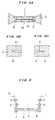
- FIG. 2A shows a captured image in which a meniscus 39 is detected.
- the meniscus 39 is indicated as a region of the melt 3 which is raised around the tip end of the seed crystal 1.
- FIG. 2B shows a captured image in which the seed crystal 1 is not held in contact with the melt, with no meniscus created.
- FIG. 2C shows a template pattern matching area A in the captured image shown in FIG. 2A.
- the temperature of the melt can be adjusted to an optimum temperature for the state in which the seed crystal 1 is held in contact with the melt.
- the temperature for crystal growth described below, can be determined highly accurately based on the optimum temperature of the melt. Accordingly, the probability of success of starting to grow a crystal and the stability of the crystal growth can greatly be increased.
- the tip end of the seed crystal may possibly be erroneously recognized as being dissolved.
- it is effective to stay in the control loop for 5 seconds after the interruption of the signal indicative of the contact between the seed crystal and the melt and to keep measuring the time with the timer when the signal indicative of the contact between the seed crystal and the melt appears again.
- the melt is cooled to a temperature capable of growing a crystal.
- the temperature is a predetermined temperature lower than the temperature of the melt which is determined based on the time in which the meniscus is retained. Specifically, if the crystal growth is anisotropic, then a crystal of silicon is linearly grown on the surface of the melt from the seed crystal.
- the solidified crystal of silicon looks white because it has an emissivity higher than the melt.
- the solidified crystal of silicon which looks white is referred to as a wingout. When the length of the wingout reaches a suitable length, the grown crystal of silicon starts being lifted.
- the surface of the melt is given a temperature distribution suitable for the crystal growth. Unless the length of the wingout is controlled at the time of starting to pull up the wingout, the temperature of the melt may be too low or high, lowering the probability of success of the starting of the crystal growth.
- the wingout starts being lifted, the seed crystal is vertically lifted to grow the crystal. If the tip end of the seed crystal is not positioned at the symmetrical center of the wingout, then the growing crystal is brought out of balance and rotates off the surface of the melt, terminating the crystal growth. In order to prevent the above difficulties from occurring, it is necessary to observe the wingout which has a length of at least 40 mm for length and asymmetry with an accuracy of at least 1 mm (2.5 %).
- the wingout has been visually observed by the operator through a viewing window.
- the operator needs to be highly skilled to observe the wingout because the viewing window is spaced from the surface of the melt by several hundreds mm and the viewing window has a limited field of view.
- the location where the seed crystal contacts the melt and the coordinates of the opposite ends of the wingout are detected from a captured image shown in FIG. 3A.
- pattern matching areas B, C are located at the transverse opposite ends of a wingout image 41 which extends from the center of the meniscus 39 and which looks white.
- the wingout 41 is detected according to a template matching process.
- the location where the seed crystal contacts the melt is determined by converting images of small regions obtained by the template matching process when the contact between the seed crystal and the melt is detected, into binary images using an average of integrated brightness values as a threshold, determining the shape of the meniscus from boundary coordinates of the binary images, and using the vertex of the shape as the coordinates of the location where the seed crystal contacts the melt.
- the positions of the tip ends of the wingout are determined in the accuracy of pixels by observing a wide area of the surface of the melt, obtaining small regions according to the template matching process, converting images of the small regions using an average of integrated brightness values as a threshold, determining the coordinates of tip ends of the wingout from the binary images, and determining maximum values of the coordinates in the direction of growth of the wingout.
- the length and asymmetry of the wingout can easily be calculated from the coordinates of the opposite ends of the wingout and the coordinates of the center of the location where the seed crystal contacts the melt.
- the measured length and asymmetry of the wingout are then compared with an expected length and an allowable value for asymmetry of the wingout. Only when the measured length and asymmetry of the wingout satisfy certain conditions, the apparatus automatically starts to pull up the grown crystal from the melt. If the measured asymmetry of the wingout exceeds the allowable value for asymmetry, then the grown crystal is not lifted, and a crystal is grown again. In this case, the asymmetric data can be fed back to effect optimization control for the temperature distribution to increase the possibility of success for a next crystal growth process.
- the position where the seed crystal contacts the melt may be automatically shifted to an optimum position to prevent the measured asymmetry of the wingout from exceeding the allowable value for asymmetry, and then a crystal may start being grown.
- the positions of the transverse opposite ends of the ribbon 5 of crystal which has been lifted over a large distance and the position of the growth slot 19 are detected according to an image processing process, and the position where the ribbon 5 of crystal is lifted is automatically controlled by the motor 27 such that the ribbon 5 of crystal is grown centrally in the growth slot 19 at all times.
- the above automatic positional control and the system for automatically optimizing the temperature distribution make it possible to allow a crystal to grow highly stably automatically.
- FIG. 4 shows a captured image showing the ribbon 5 of crystal that is pulled from the melt 3.
- the coordinates of the positions of the transverse opposite ends of the ribbon 5 of crystal are detected from the image shown in FIG. 4. Since the solid/liquid phase interfaces are bright as a whole and have a blurred profile due to a rise of the surface of the melt which is caused by the surface tension developed by the lifting of the crystal, they are not suitable for the detection of the coordinates of the transverse opposite ends of the ribbon 5 of crystal which is being grown.
- the coordinates of the transverse opposite ends of the ribbon 5 of crystal are determined at two points above the solid/liquid phase interfaces and statistically processed to draw approximate lines H, I, and the coordinates J, K of the transverse opposite ends of the ribbon 5 of crystal near the solid/liquid phase interfaces are determined by extending the approximate lines H, I.
- the accuracy of the approximate lines H, I increases if the region which is measured is wide and the number of data is large.
- the crystal which is being grown has a large brightness gradient in the vertical direction due to the temperature gradient, it is highly difficult to obtain a threshold for converting images of the ends of the crystal into binary images in a wide region with a sufficient resolution.
- small regions D, E, F, G near the ends of the crystal are established with respect to a plurality of vertical positions where the brightness can be regarded as constant, according to a template matching process, the brightness values of the images of the small regions D, E, F, G are differentiated to emphasize their edges, the brightness values are converted into binary levels with an average of integrated brightness values, and the coordinates of the transverse opposite ends of the ribbon of crystal are obtained from a distribution of coordinates of the binary levels.
- These coordinate data are approximated to straight lines by a statistically approximating means, obtaining the hypothetical straight lines H, I.
- an area near a central straight region thereof is detected by a template matching process, and a small region in the vicinity thereof is converted into a binary image with an average of integrated brightness values, determining the coordinates of the shape.
- the coordinates are then statistically approximated to a hypothetical straight line, which is translated to a desired position in the growth slot. Points of intersection between the translated straight line and the approximate straight lines at the left and right ends of the crystal are determined and used as the coordinates of the ends of the crystal.
- a small region in the vicinity of the left and right lower ends of the growth slot is established by template matching process, and converted into a binary image with an average of integrated brightness values.
- the coordinates of the left and right ends of the growth slot are determined from the binary image.
- a deformation of the crystal can easily be calculated by comparing the left and right ends of the growth slot with the left and right ends of the crystal.
- an average value over a certain period of time may be used, and the moving stage of the crystal lifter may be electrically actuated to correct a displacement difference for thereby keeping the crystal at the center of the growth slot in an unattended fashion.
- image information may also be read from the left and right video cameras, and three-dimensional image processing may be carried out, so that the crystal can positionally corrected three-dimensionally with an electrically actuated xy ⁇ stage.
- the apparatus is controlled in a sequence to immediately lower the temperature of the melt, quickly remove the crystal until the lower end thereof is brought out of the furnace, and issue some warning when the crystal is displaced completely out of the furnace. In this manner, the operation of the apparatus after the end of the crystal growth is automatized.
- any of various image processing processes may be employed depending on the relationship between the processing speed and the detecting accuracy.
Landscapes
- Chemical & Material Sciences (AREA)
- Engineering & Computer Science (AREA)
- Crystallography & Structural Chemistry (AREA)
- Materials Engineering (AREA)
- Metallurgy (AREA)
- Organic Chemistry (AREA)
- Crystals, And After-Treatments Of Crystals (AREA)
Abstract
Description
Claims (13)
- A method of growing a ribbon of crystal, comprising:lowering a seed crystal toward a melt;detecting a contact between the seed crystal and the melt with an image captured by an imaging device;adjusting the temperature of said melt to keep a meniscus of the melt in contact with the seed crystal;detecting a wingout with an image captured by said imaging device; andstarting to lift a ribbon of crystal following said wingout from said melt.
- A method according to claim 1, wherein said detecting a contact between the seed crystal and the melt comprises:lowering said seed crystal by a predetermined distance;stopping said seed crystal for a given period of time measured by a timer;attempting to detect a contact between the seed crystal and the melt while said seed crystal is stopped; andrepeating said lowering, stopping, and attempting steps until a contact between the seed crystal and the melt is detected.
- A method according to claim 1, wherein said detecting said wingout comprises:detecting coordinates of said seed crystal in a region of contact between said seed crystal and said melt, and a length and symmetry of said wingout extending from said coordinates.
- A method of growing a crystal, comprising:lowering a seed crystal toward a melt;detecting a contact between the seed crystal and the melt with an image by template matching process;adjusting the temperature of said melt; andstarting to lift a crystal.
- An apparatus for growing a ribbon of crystal, comprising:a container containing a melt in a crucible;a lifter/lowering device for lowering a seed crystal into said melt and lifting a seed crystal away from said melt;an imaging device for capturing images of said surface of said melt and a ribbon of crystal produced from said melt; anda controller for controlling conditions for growing the ribbon of crystal based on the images captured by said imaging device.
- An apparatus according to claim 5, wherein said imaging device captures an image of solid/liquid phase interfaces of said melt.
- An apparatus according to claim 5, wherein said imaging device captures an image of meniscus formed by contact between the seed crystal and the melt.
- An apparatus according to claim 7, wherein said controller adjusts a temperature of said melt so as to keep said meniscus on the melt over a predetermined time.
- An apparatus according to claim 8, wherein said controller lowers the temperature of said melt to create a wingout extending from said seed crystal.
- An apparatus according to claim 9, wherein said controller starts to lift a ribbon of crystal after detecting said wingout with an image captured by said imaging device.
- An apparatus according to claim 5, wherein said apparatus is provided with at least a video camera disposed substantially directly above the crucible for observing a surface of the melt and a growth of a ribbon crystal through a growth slot.
- An apparatus according to claim 5, wherein said apparatus is provided with measuring means of length and a symmetry of a wingout.
- An apparatus according to claim 5, wherein said apparatus is provided with measuring means of temperature of the melt by determining how long a meniscus is retained.
Applications Claiming Priority (2)
| Application Number | Priority Date | Filing Date | Title |
|---|---|---|---|
| JP2000275315A JP4056206B2 (en) | 2000-09-11 | 2000-09-11 | Ribbon crystal growth method and apparatus |
| JP2000275315 | 2000-09-11 |
Publications (2)
| Publication Number | Publication Date |
|---|---|
| EP1186687A2 true EP1186687A2 (en) | 2002-03-13 |
| EP1186687A3 EP1186687A3 (en) | 2003-11-19 |
Family
ID=18760960
Family Applications (1)
| Application Number | Title | Priority Date | Filing Date |
|---|---|---|---|
| EP01121606A Withdrawn EP1186687A3 (en) | 2000-09-11 | 2001-09-11 | Method of and apparatus for growing ribbon of crystal |
Country Status (4)
| Country | Link |
|---|---|
| US (1) | US6471768B2 (en) |
| EP (1) | EP1186687A3 (en) |
| JP (1) | JP4056206B2 (en) |
| AU (1) | AU775147B2 (en) |
Cited By (2)
| Publication number | Priority date | Publication date | Assignee | Title |
|---|---|---|---|---|
| WO2012044909A1 (en) * | 2010-10-01 | 2012-04-05 | Evergreen Solar, Inc. | Sheet wafer defect mitigation |
| CN108344742A (en) * | 2018-04-13 | 2018-07-31 | 太原理工大学 | A kind of sapphire inoculation detection device and method based on multiple image movable information |
Families Citing this family (6)
| Publication number | Priority date | Publication date | Assignee | Title |
|---|---|---|---|---|
| JP4059639B2 (en) * | 2001-03-14 | 2008-03-12 | 株式会社荏原製作所 | Crystal pulling device |
| JP4561513B2 (en) | 2005-07-22 | 2010-10-13 | 株式会社Sumco | Liquid surface position adjusting mechanism and liquid surface position adjusting method of single crystal pulling apparatus, liquid surface position adjusting mechanism and liquid surface aligning method of single crystal pulling apparatus |
| WO2015047816A1 (en) * | 2013-09-30 | 2015-04-02 | Gt Crystal Systems, Llc | Method of automatically measuring seed melt back of crystalline material |
| US9574285B2 (en) * | 2014-12-10 | 2017-02-21 | Varian Semiconductor Equipment Associates, Inc. | Apparatus and method for monitoring and controlling thickness of a crystalline layer |
| WO2026039948A1 (en) * | 2024-08-19 | 2026-02-26 | 眉山博雅新材料股份有限公司 | Device for crystal growth and crystal growth method |
| CN119413291B (en) * | 2025-01-06 | 2026-02-17 | 苏州南智芯材科技有限公司 | Temperature calibration method, measurement method and measuring device for crystal growth furnace |
Family Cites Families (8)
| Publication number | Priority date | Publication date | Assignee | Title |
|---|---|---|---|---|
| US4217165A (en) * | 1978-04-28 | 1980-08-12 | Ciszek Theodore F | Method of growing a ribbon crystal particularly suited for facilitating automated control of ribbon width |
| US4318769A (en) * | 1979-01-15 | 1982-03-09 | Mobil Tyco Solar Energy Corporation | Method of monitoring crystal growth |
| US4239583A (en) * | 1979-06-07 | 1980-12-16 | Mobil Tyco Solar Energy Corporation | Method and apparatus for crystal growth control |
| JPS5637295A (en) * | 1979-08-29 | 1981-04-10 | Japan Solar Energ Kk | Ribbonlike crystal producing apparatus |
| US6093244A (en) * | 1997-04-10 | 2000-07-25 | Ebara Solar, Inc. | Silicon ribbon growth dendrite thickness control system |
| JPH10279383A (en) | 1997-03-31 | 1998-10-20 | Super Silicon Kenkyusho:Kk | Safety monitor device for apparatus for growing single crystal |
| JP4151863B2 (en) | 1999-02-19 | 2008-09-17 | コバレントマテリアル株式会社 | Method and apparatus for detecting vibration of single crystal ingot in semiconductor single crystal pulling apparatus |
| JP4079548B2 (en) | 1999-04-30 | 2008-04-23 | 株式会社荏原製作所 | Crystal continuous pulling device |
-
2000
- 2000-09-11 JP JP2000275315A patent/JP4056206B2/en not_active Expired - Fee Related
-
2001
- 2001-09-06 US US09/946,518 patent/US6471768B2/en not_active Expired - Fee Related
- 2001-09-07 AU AU68806/01A patent/AU775147B2/en not_active Ceased
- 2001-09-11 EP EP01121606A patent/EP1186687A3/en not_active Withdrawn
Cited By (2)
| Publication number | Priority date | Publication date | Assignee | Title |
|---|---|---|---|---|
| WO2012044909A1 (en) * | 2010-10-01 | 2012-04-05 | Evergreen Solar, Inc. | Sheet wafer defect mitigation |
| CN108344742A (en) * | 2018-04-13 | 2018-07-31 | 太原理工大学 | A kind of sapphire inoculation detection device and method based on multiple image movable information |
Also Published As
| Publication number | Publication date |
|---|---|
| US6471768B2 (en) | 2002-10-29 |
| EP1186687A3 (en) | 2003-11-19 |
| AU775147B2 (en) | 2004-07-22 |
| AU6880601A (en) | 2002-03-14 |
| JP2002087899A (en) | 2002-03-27 |
| JP4056206B2 (en) | 2008-03-05 |
| US20020029735A1 (en) | 2002-03-14 |
Similar Documents
| Publication | Publication Date | Title |
|---|---|---|
| KR101028684B1 (en) | Silicon single crystal pulling method | |
| US5846318A (en) | Method and system for controlling growth of a silicon crystal | |
| US5653799A (en) | Method for controlling growth of a silicon crystal | |
| US6171391B1 (en) | Method and system for controlling growth of a silicon crystal | |
| US6471768B2 (en) | Method of and apparatus for growing ribbon of crystal | |
| US10233565B2 (en) | Single-crystal manufacturing apparatus and method for controlling melt surface position | |
| JP5924090B2 (en) | Single crystal pulling method | |
| KR102816158B1 (en) | Method for producing single crystals | |
| JP2007031175A (en) | Liquid surface position adjusting mechanism and liquid surface position adjusting method of single crystal pulling apparatus, liquid surface position adjusting mechanism and liquid surface aligning method of single crystal pulling apparatus | |
| CN114399488A (en) | Liquid gap monitoring method, storage medium, terminal and crystal pulling equipment | |
| JP6642234B2 (en) | Method and apparatus for producing single crystal | |
| KR200396732Y1 (en) | Silicon crystal growth controllar using image binarization | |
| JP7571618B2 (en) | Method for detecting surface condition of raw material melt, method for producing single crystal, and CZ single crystal production apparatus | |
| CN117187942B (en) | A method and device for controlling the position of the crucible during crystal pulling | |
| JP2004099346A (en) | Single crystal pulling apparatus and single crystal pulling method | |
| KR20240155336A (en) | Method and device for manufacturing silicon single crystal and method for manufacturing silicon wafer | |
| JP6090501B2 (en) | Single crystal pulling method | |
| JP2000026197A (en) | Production of silicon single crystal and equipment therefor |
Legal Events
| Date | Code | Title | Description |
|---|---|---|---|
| PUAI | Public reference made under article 153(3) epc to a published international application that has entered the european phase |
Free format text: ORIGINAL CODE: 0009012 |
|
| AK | Designated contracting states |
Kind code of ref document: A2 Designated state(s): AT BE CH CY DE DK ES FI FR GB GR IE IT LI LU MC NL PT SE TR |
|
| AX | Request for extension of the european patent |
Free format text: AL;LT;LV;MK;RO;SI |
|
| PUAL | Search report despatched |
Free format text: ORIGINAL CODE: 0009013 |
|
| AK | Designated contracting states |
Kind code of ref document: A3 Designated state(s): AT BE CH CY DE DK ES FI FR GB GR IE IT LI LU MC NL PT SE TR |
|
| AX | Request for extension of the european patent |
Extension state: AL LT LV MK RO SI |
|
| 17P | Request for examination filed |
Effective date: 20040428 |
|
| 17Q | First examination report despatched |
Effective date: 20040608 |
|
| AKX | Designation fees paid |
Designated state(s): DE ES FR GB IT NL |
|
| STAA | Information on the status of an ep patent application or granted ep patent |
Free format text: STATUS: THE APPLICATION IS DEEMED TO BE WITHDRAWN |
|
| 18D | Application deemed to be withdrawn |
Effective date: 20081022 |