EP1186540A1 - Carton with wedge-shaped compartments - Google Patents
Carton with wedge-shaped compartments Download PDFInfo
- Publication number
- EP1186540A1 EP1186540A1 EP01420189A EP01420189A EP1186540A1 EP 1186540 A1 EP1186540 A1 EP 1186540A1 EP 01420189 A EP01420189 A EP 01420189A EP 01420189 A EP01420189 A EP 01420189A EP 1186540 A1 EP1186540 A1 EP 1186540A1
- Authority
- EP
- European Patent Office
- Prior art keywords
- panel
- articulated
- fold line
- case according
- counter
- Prior art date
- Legal status (The legal status is an assumption and is not a legal conclusion. Google has not performed a legal analysis and makes no representation as to the accuracy of the status listed.)
- Granted
Links
Images


Classifications
-
- B—PERFORMING OPERATIONS; TRANSPORTING
- B65—CONVEYING; PACKING; STORING; HANDLING THIN OR FILAMENTARY MATERIAL
- B65D—CONTAINERS FOR STORAGE OR TRANSPORT OF ARTICLES OR MATERIALS, e.g. BAGS, BARRELS, BOTTLES, BOXES, CANS, CARTONS, CRATES, DRUMS, JARS, TANKS, HOPPERS, FORWARDING CONTAINERS; ACCESSORIES, CLOSURES, OR FITTINGS THEREFOR; PACKAGING ELEMENTS; PACKAGES
- B65D5/00—Rigid or semi-rigid containers of polygonal cross-section, e.g. boxes, cartons or trays, formed by folding or erecting one or more blanks made of paper
- B65D5/42—Details of containers or of foldable or erectable container blanks
- B65D5/44—Integral, inserted or attached portions forming internal or external fittings
- B65D5/50—Internal supporting or protecting elements for contents
- B65D5/5002—Integral elements for containers having tubular body walls
- B65D5/5016—Integral elements for containers having tubular body walls formed by folding inwardly of extensions hinged to the side edges of the body
-
- B—PERFORMING OPERATIONS; TRANSPORTING
- B65—CONVEYING; PACKING; STORING; HANDLING THIN OR FILAMENTARY MATERIAL
- B65D—CONTAINERS FOR STORAGE OR TRANSPORT OF ARTICLES OR MATERIALS, e.g. BAGS, BARRELS, BOTTLES, BOXES, CANS, CARTONS, CRATES, DRUMS, JARS, TANKS, HOPPERS, FORWARDING CONTAINERS; ACCESSORIES, CLOSURES, OR FITTINGS THEREFOR; PACKAGING ELEMENTS; PACKAGES
- B65D5/00—Rigid or semi-rigid containers of polygonal cross-section, e.g. boxes, cartons or trays, formed by folding or erecting one or more blanks made of paper
- B65D5/42—Details of containers or of foldable or erectable container blanks
- B65D5/44—Integral, inserted or attached portions forming internal or external fittings
- B65D5/48—Partitions
- B65D5/48002—Partitions integral
- B65D5/48014—Partitions integral formed by folding extensions hinged to the side edges of a tubular body
Definitions
- the present invention relates to the technical field of packaging and packaging of various products in a case formed by folding a blank pre-cut from cardboard or the like.
- the cases used generally have a substantially shaped parallelepipedic which, if it is able to contain the product to be packaged, is not not always likely to provide the latter with sufficient timing to preserve integrity.
- corner housing can also be useful for the packaging, for example, of products in sachets which have one end thicker than the other.
- US Patent 3,370,776 and the model DE 29 902 027 have both proposed a packaging case made to from a pre-cut blank of compact cardboard.
- This packaging case is assembled by folding to include a peripheral envelope with hinged panels intended to form a substantially parallelepipedic case body, flaps and closing flaps of the transverse ends of the body.
- the case includes, also, an internal wedging structure forming a folding extension and counter-fixed to an articulated panel and comprising a connecting strip, a panel median and a counter-panel, delimited and articulated together by fold lines oriented so that the middle panel extends diagonally in the body case and delimits two compartments substantially in the form of wedges.
- the connecting strip and the counter-panel are articulated on two diametrically opposite parts of the middle panel, so that the connecting strip and the counter-panel are folded in two directions opposite to be arranged each in a compartment, wedge-shaped, separate.
- the manner of producing the packaging case according to the prior art does not not allow to obtain a median panel of exactly rectangular plan shape and one of the corners of the middle panel is truncated so that the two corner compartments communicate through an opening not occupied by the panel median.
- this case is characterized in that the middle panel is connected to the connecting strip by a hinge strip intended to be counter-folded against the connecting strip.
- the middle panel has an exactly rectangular shape.
- Fig. 1 is a flat view of a precut blank for producing a case according to documents US Pat. No. 3,370,776 and DE 29 9 02 027.
- Fig . 2 is a perspective of the case according to the prior art produced by folding the blank illustrated in FIG. 1 showing, more particularly, the internal structure of the shimming of the case.
- Fig. 3 is a section along the plane III-III of FIG. 2 of this case according to the prior art.
- Fig. 4 is a plan view of a blank precut for the constitution of a case according to the invention.
- Fig. 5 is a perspective of a case according to the invention, formed from the blank illustrated in FIG. 4.
- Fig. 6 is a longitudinal section along the plane VI-VI of FIG. 5.
- Fig. 7 is a cross section along the plane VII-VII of FIG. 5.
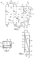
- Fig. 8 is a plan view of a precut blank for forming a variant of the case according to the invention.
- Fig. 9 is a longitudinal section, similar to FIG. 6, of the case obtained from the blank according to FIG. 8.
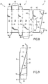
- Fig. 10 is a plan view of a pre-cut blank for the formation of a case according to the invention, comprising an internal reinforcement structure of the bottom of one of the corner compartments.
- Fig. 11 is a longitudinal section similar to that of FIG. 6 of a case made from a precut blank illustrated in FIG. 10.
- Fig. 12 is a cross section along the line XII-XII of FIG. 11.
- Fig. 13 is a plan view of a pre-cut blank for forming a case, substantially similar to that of FIGS. 10 to 12 but having another embodiment of the internal reinforcement structure of the bottom of one of the compartments.
- Fig. 14 is a longitudinal section of a case obtained from the blank illustrated in FIG. 13.
- Fig. 15 is a cross section along the line XV-XV of FIG. 14.
- FIGS . 1 to 3 recall, in detail, the teaching of documents US 3,370,776 and DE 29,902,027.
- the precut blank for producing by folding a case according to the prior art, comprises a first part A , called the peripheral envelope, which comprises four panels 1, 2, 3, 4 articulated one after the other others by parallel fold lines 5, 6, 7 . Some panels, 1 and 3 , are extended at the end by folding flaps 8 , while the other two panels, 2 and 4 , are each provided with a shutter for closing the transverse ends of the case body 10 and 11 , respectively. high and low.
- the pre-cut blank also includes a second part B , called internal wedging, constituted in particular by a connecting strip 12 connected to the last articulated panel 4 by a fold line 13 parallel to that 7 separating the last panel 4 from the adjacent panel 3.
- This connecting strip is intended to provide a fixing surface for the first panel 1 , in order to form the case body, as illustrated in FIG. 2.
- the internal wedging part B also includes a middle panel 15 and a counter panel 16 which extend from the connecting strip, being delimited by two fold lines 17 and 18, parallel to each other and forming an angle with the fold line 13.
- the counter panel 16 has a bearing edge 19 intended to be placed in the angle defined by the fold line 6.
- the angle of the middle panel 15 located on the side of the connecting strip 12 is truncated so that the middle panel 15 does not does not have an exactly rectangular shape.
- the fold lines 17 and 18 are diametrically opposite with respect to the middle panel 15, so that the counter-panel 16 and the connecting strip 12 are connected to opposite portions, respectively low and high, of the middle panel 15 .
- the fold lines 13 and 17 converge downwardly, while the edge 19 and line 18 converge upwardly from the case.
- the middle panel 15 extends, when the case is mounted, as illustrated in FIG. 2, diagonally in the case body E formed from part A of the precut blank.
- the middle panel 15 then delimits two compartments 20, 21 substantially in the form of a wedge or prism.
- the corner C of one of the compartments is open to the other compartment so that the two compartments communicate.
- this opening C is unsightly when the case E is opened.
- the invention therefore aims to remedy these drawbacks by proposing, in particular, to arrange, inside the case, two corner compartments perfectly partitioned.
- the case according to the invention is produced from a precut blank, generally designated by the reference 30 and illustrated in FIG. 4 on which the edges and cutting lines are shown in solid line, while the fold lines are shown in phantom.
- the blank 30 can be made of any suitable material and preferably, but not exclusively, of compact cardboard.
- the precut blank 30 comprises a first part I , called the peripheral envelope, intended to form, by folding, the body of the case.
- This first part I comprises, in particular, four panels 31, 32, 33, 34 articulated, one after the other, by parallel fold lines 35, 36, 37. Some panels, 31 and 33, are extended at the end by folding flaps 38, while the other two panels, 32 and 34, are each provided with a closing flap 40 and 41 of the ends of the case body, respectively high and low.
- the blank 30 also comprises a second part II, known as an internal wedging structure, which is made up, in particular, of a connecting strip 42 extending in the extension of the last articulated panel 34.
- the connecting strip 42 is connected to the last panel 34 by a fold line 43 parallel to that 37 separating the last panel 34 from the adjacent panel 33.
- the internal structural part II also includes a hinge band 44 connecting the connecting band 42 to a middle panel 45.
- the hinge band 44 is separated from the connecting band 42 by a fold line 46 which forms with the fold line 43 an angle ⁇ while converging towards a so-called lower end of the case or of the blank 30.
- the articulation band 44 is separated from the middle panel 45 by a fold line 47. According to the example illustrated , the articulation band 44 extends only over a part of the height of the connecting band 42 and of the median panel 45, in the lower part of the latter which are then separated in the upper part by a notch in "U " 48.
- the median panel has, opposite the articulation band 44, a counter panel 49 which is separated from the median panel 45 by a fold line 50, parallel to the fold line 47 separating the median panel 45 from the hinge band.
- the fold line 47 is parallel to the fold line 43 .
- the middle panel 45 has a rectangular shape and that none of its angles is truncated. This difference between the invention and the prior art is clear from the comparative analysis of FIGS . 1 and 4.
- the shaping of the case according to the invention, from the blank 30, is carried out for example, by successive and alternating folding, along lines 46, 47 and 50, of part II of the blank in, respectively , the direction of the arrows F 1 , F 2 and F 3 .
- the articulation band 44 is folded against the internal face of the connecting band 42.
- the articulation band 44 is then fixed on the connecting band 42 by any means suitable and preferably by gluing.
- the mounting of the case continues by a successive folding along the lines 35, 36, 37 and 43 of the part I of peripheral envelope, so as to come fix the first articulated panel 31 against the connecting strip 42 by all suitable means, such as, for example, by bonding.
- a bearing edge 51 which is placed at the angle defined by the fold line 37.
- the edge 51 defines with the line folding 50 an angle ⁇ which corresponds to the inclination of the middle panel 45 inside the case body defined by the articulated panels 31 to 34.
- the folding line 50 and the bearing edge 51 converge towards the so-called lower part of the case.
- the connecting strip 42 is located against the first panel 31, while the counter panel 49 is located against the third panel 33.
- the case thus formed is illustrated in perspective in FIG. 5 and in section in FIGS. 6 and 7. It appears from FIG. 5 that the middle panel 45 extends diagonally in the case body. The position of the middle panel 45 is shown clearly in FIG. 6 and it appears that the inclination of the panel 45 defines, in the case body, two compartments 52 and 53 of substantially prismatic or corner shape.
- the exactly rectangular shape of the middle panel makes it possible to perfectly partition and separate the two compartments 52 and 53. It should be noted that preferably the middle panel 45 has a length sufficient to extend into the case from the lower edge 54 of the last articulated panel 34 to the upper edge 55 of the second articulated panel 32.
- the middle panel 45 When the object intended to be packaged in one of the compartments 52, 53 of the case is curved, the middle panel 45 preferably has two slots 56 arranged in a cross to allow the adaptation of the middle panel 45 and of the compartment 52 to the shape of the object. According to the invention one or more cutouts could also be made in the middle panel to define one or more wedging cells for packaged products.
- the middle panel 45 has, at its lower end, an articulated retaining lug 57 intended to bear on the internal face of the articulated panel 32 located opposite the lower end of the middle panel 45 .
- the retaining tab 57 extends from a fold line 58 perpendicular to the fold lines 47 and 50 and has, opposite the line 58 a bearing edge 59 parallel to the latter. .
- the retaining tab 57 is folded towards the inside of the case so as to place the edge 59 in abutment against the internal face of the second hinged panel 32.
- the use of the retaining tab 57 advantageously makes it possible to reinforce the point of the compartment 52 by preventing the lower end of the middle panel 45 from moving away from the hinged panel 34 during the introduction of an object in compartment 52.
- Figs. 8 and 9 illustrate another embodiment of the case according to the invention, according to which the blank 30, constituting the case, has the same elements as those described in relation to FIG. 4, the middle panel 45 does not, however, have a holding tab in the lower part.
- This other embodiment differs from that illustrated in FIG. 4 in that the counter panel 49 has, opposite the middle panel 45, a reinforcement lug 70 which is separated from the counter panel 49 by a fold line 71 parallel to the support edge 51 and located in continuation of the latter.
- the fold line 71 then achieves, with the fold line 50, an angle ⁇ .
- the reinforcement lug 70 is preferably connected to the counter panel 49 in the lower part of the latter, towards the point of convergence of the fold lines 50 and 71.
- the reinforcement lug 70 defines the opposite from line 71 a bearing edge 72.
- the precut blank, thus formed, is shaped substantially in the same way as that has been described in relation to FIG . 4 , so as to constitute the case according to the invention.
- the reinforcing lug 70 is folded against the panel 49 by the formation of the fold line 71. This last fold is carried out so that, after the shaping of the case, as illustrated in fig . 12 , the reinforcing lug 70 is pressed against the articulated panel 33 and its edge 72 is in abutment against the panel 32 in the angle formed by the fold line 36.
- the lug 70 reinforces the lower part of the compartment 52 and the triangular faces corresponding to the panels 33 of the compartment 53. In addition, the lug 70 thus ensures immobilization and wedging of the counter panel 49 contributing to the correct positioning of the middle panel 45.
- Figs. 10 to 12 illustrate another embodiment of the case according to the invention according to which the blank 30 constituting the case has the same elements as those described in relation to FIG. 4 the middle panel, however, does not have a retaining tab at the bottom.
- the blank 30 also has a folding extension III intended to constitute an internal reinforcement structure.
- the reinforcement extension III extends in the lower part of the third articulated panel 33 from a fold line 80 perpendicular to the fold lines 36 and 37.
- the reinforcement extension III then comprises two flaps 81 and 82 separated by a fold line 83 parallel to the fold line 80. It should be noted that the fold line 80 contributes to delimiting the lower edge of the third articulated panel 33.
- the shaping of the case from the blank 30, thus formed, is carried out in a manner substantially similar to that described in relation to FIG . 4 .
- the folding extension III is brought towards the inside of the case so as to interpose the second flap 82 between the middle panel 45 and the internal face of the second articulated panel 32 as shown. of figs . 11 and 12.
- the second flap 82 then has a width sufficient to be in permanent support on the median panel 45 and the articulated panel 32, so as to wedge the median panel 45.
- This advantageous arrangement of the invention thus makes it possible to strengthen the lower corner of the first compartment 52 so as to prevent the bottom of the middle panel 45 from being separated from the fourth articulated panel 34 when an object is introduced into the compartment 52.
- Figs. 13 to 15 illustrate an alternative embodiment of the case according to the invention as described in relation to FIGS . 10 to 12.
- the folding extension III extends from the fold line 80, delimiting the edge of the third articulated panel 33, and comprises three articulated bands 85, 86 and 87 delimited by fold lines 88 and 89 parallel to the first fold line 80.
- the extreme articulated band 87 also has, opposite the articulated panel 33, a counter-fixing band 90 separated from the extreme articulated band 87 by a fold line 91 parallel to the lines folding 80, 88 and 89.
- the shaping of the case from the precut blank thus formed is carried out as follows.
- the reinforcement extension III is folded down on the internal face of the third articulated panel 33, the counter-fixing strip 90 then being fixed against the latter by any suitable means and, preferably by gluing. During this operation, the different fold lines 88, 89 and 91 are marked to allow subsequent shaping of the reinforcement III, as will appear later.
- the extension III is folded back inside the case, so as to interpose said extension III between the middle panel 45 and the internal face of the second articulated panel 32, as shown in FIG . 14 .
- the articulated bands 85 and 87 extend substantially parallel to the bottom of the case and perpendicular to the articulated panels 31 to 34 and the intermediate articulated band 86 extends substantially vertically, as shown in FIG. 4.
- the flap 41 can be closed. It should be noted that, to ensure good wedging of the lower part of the middle panel 45 , the extreme articulated band 87 then has a width substantially equal to the distance separating the internal face of the second articulated panel 32 from the face opposite the panel. median 45.
- the reinforcing structure 45 prevents the lower part of the middle panel 45 from moving away from the last articulated panel 34 when an object is introduced into the first corner compartment 52.
Abstract
Description
La présente invention concerne le domaine technique de l'emballage et du conditionnement de produits divers dans un étui formé par pliage d'un flan prédécoupé de carton ou analogue.The present invention relates to the technical field of packaging and packaging of various products in a case formed by folding a blank pre-cut from cardboard or the like.
Les étuis utilisés présentent, généralement, une forme sensiblement parallélépipèdique qui, si elle est à même de contenir le produit à conditionner, n'est pas toujours susceptible de procurer à ce dernier un calage suffisant pour en préserver l'intégrité.The cases used generally have a substantially shaped parallelepipedic which, if it is able to contain the product to be packaged, is not not always likely to provide the latter with sufficient timing to preserve integrity.
Afin de tenir compte de la forme particulière du contenu, l'étui doit donc comprendre une structure interne de calage qui définit alors un logement d'accueil pour le produit à conditionner.In order to take into account the particular form of the content, the case must therefore understand an internal wedging structure which then defines a reception accommodation for the product to be packaged.
Tel est, par exemple, le cas pour le conditionnement d'un tube réalisé à partir d'une gaine en matière déformable et fermé par le fond, de sorte que le tube présente, au niveau de son embouchure, une forme sensiblement cylindrique qui va en s'aplatissant pour présenter une forme à l'extrémité opposée sensiblement prismatique. En effet, pour assurer un calage efficace d'un tel tube, il est nécessaire de disposer d'un logement d'accueil, en forme de coin ou de prisme.This is, for example, the case for the packaging of a tube produced at from a sheath of deformable material and closed at the bottom, so that the tube has, at its mouth, a substantially cylindrical shape which goes flattening to present a shape at the opposite end substantially prismatic. Indeed, to ensure an efficient wedging of such a tube, it is necessary to have a reception accommodation, in the form of a wedge or a prism.
La présence de logements en coin peut également s'avérer utile pour le conditionnement, par exemple, de produits en sachets qui présentent une extrémité plus épaisse que l'autre.The presence of corner housing can also be useful for the packaging, for example, of products in sachets which have one end thicker than the other.
Afin de répondre à ce besoin, le brevet US 3 370 776 et le modèle d'utilité DE 29 902 027 ont tous deux proposé un étui de conditionnement réalisé à partir d'un flan prédécoupé de carton compact. Cet étui de conditionnement est monté par pliage pour comporter une enveloppe périphérique à panneaux articulés destinés à former un corps d'étui sensiblement parallélépipèdique, des volets et des rabats de fermeture des extrémités transversales du corps. L'étui comprend, également, une structure interne de calage formant un prolongement rabattable et contre-fixable d'un panneau articulé et comportant une bande de liaison, un panneau médian et un contre-panneau, délimités et articulés entre eux par des lignes de pliage orientées de manière que le panneau médian s'étende en diagonale dans le corps d'étui et délimite deux compartiments sensiblement en forme de coins.In order to meet this need, US Patent 3,370,776 and the model DE 29 902 027 have both proposed a packaging case made to from a pre-cut blank of compact cardboard. This packaging case is assembled by folding to include a peripheral envelope with hinged panels intended to form a substantially parallelepipedic case body, flaps and closing flaps of the transverse ends of the body. The case includes, also, an internal wedging structure forming a folding extension and counter-fixed to an articulated panel and comprising a connecting strip, a panel median and a counter-panel, delimited and articulated together by fold lines oriented so that the middle panel extends diagonally in the body case and delimits two compartments substantially in the form of wedges.
Selon ces deux documents, la bande de liaison et le contre-panneau sont articulés sur deux parties diamétralement opposées du panneau médian, de sorte que la bande de liaison et le contre-panneau se trouvent repliés selon deux directions opposées pour être disposés chacun dans un compartiment, en forme de coin, distinct.According to these two documents, the connecting strip and the counter-panel are articulated on two diametrically opposite parts of the middle panel, so that the connecting strip and the counter-panel are folded in two directions opposite to be arranged each in a compartment, wedge-shaped, separate.
La façon de réaliser l'étui de conditionnement selon l'art antérieur ne permet pas d'obtenir un panneau médian de forme en plan exactement rectangulaire et l'un des angles du panneau médian est tronqué de sorte que les deux compartiments en coin communiquent par une ouverture non occupée par le panneau médian.The manner of producing the packaging case according to the prior art does not not allow to obtain a median panel of exactly rectangular plan shape and one of the corners of the middle panel is truncated so that the two corner compartments communicate through an opening not occupied by the panel median.
Or, la présence de cette ouverture est inesthétique et préjudiciable à la fonction de cloisonnement du panneau médian.However, the presence of this opening is unsightly and detrimental to the partitioning function of the middle panel.
Afin de remédier à cet inconvénient, il est donc apparu le besoin de disposer d'un étui de conditionnement dont la structure permet d'obtenir un panneau médian de forme exactement rectangulaire de manière à cloisonner l'étui en deux compartiments en coin qui ne communiquent pas entre eux.In order to remedy this drawback, it therefore appeared the need to have a packaging case whose structure makes it possible to obtain a panel median of exactly rectangular shape so as to partition the case in two corner compartments which do not communicate with each other.
Pour atteindre cet objectif, l'invention concerne un étui de conditionnement, du type réalisé à partir d'un flan prédécoupé et monté par pliage pour comporter
- une enveloppe périphérique à panneaux articulés destinée à former un corps d'étui, des volets et des rabats de fermeture des extrémités transversales du corps d'étui,
- et une structure interne de calage formant un prolongement rabattable et contre-fixable d'un panneau articulé et comprenant une bande de liaison, un panneau médian et un contre-panneau délimités et articulés entre eux par des lignes de pliage orientées de manière que le panneau médian s'étende en diagonale dans le corps d'étui et délimite deux compartiments sensiblement en forme de coins.
- a peripheral envelope with articulated panels intended to form a case body, shutters and flaps for closing the transverse ends of the case body,
- and an internal wedging structure forming a folding and counter-fixed extension of an articulated panel and comprising a connecting strip, a median panel and a counter-panel delimited and articulated together by fold lines oriented so that the panel median extends diagonally in the case body and delimits two compartments substantially in the form of wedges.
Selon l'invention, cet étui est caractérisé en ce que le panneau médian est relié à la bande de liaison par une bande d'articulation destinée à être contrepliée contre la bande de liaison.According to the invention, this case is characterized in that the middle panel is connected to the connecting strip by a hinge strip intended to be counter-folded against the connecting strip.
L'invention vise, également, pour la réalisation de l'étui, un flan prédécoupé comprenant, d'une part, une première partie, dite d'enveloppe, composée de quatre panneaux articulés les uns à la suite des autres par des lignes de pliage parallèles, certains desdits panneaux étant prolongés en bout par des rabats repliables, alors que d'autres sont pourvus de volets de fermeture du corps d'étui formé par lesdits panneaux et, d'autre part, une seconde partie, dite de calage interne, qui comprend :
- une bande de liaison reliée au dernier panneau articulé, par une ligne de pliage parallèle à celle séparant le dernier panneau articulé du panneau adjacent, et destinée à offrir une surface de fixation pour le premier panneau, afin de former le corps d'étui,
- une bande d'articulation reliée à la bande de liaison par une ligne de pliage formant un angle α avec la ligne de pliage séparant la bande de liaison du panneau articulé,
- un panneau médian et un contre-panneau qui s'étendent à partir de la bande d'articulation en étant délimité par deux lignes de pliage, parallèles entre elles, le contre-panneau présentant, à l'opposé de la ligne de pliage, un bord d'appui convergeant sensiblement avec la ligne de pliage séparant le contre-panneau du panneau médian dans la même direction que celle dans laquelle convergent les lignes de pliage entre, d'une part, le dernier panneau articulé et la bande de liaison et, d'autre part, la bande de liaison et la bande d'articulation.
- a connecting strip connected to the last articulated panel, by a fold line parallel to that separating the last articulated panel from the adjacent panel, and intended to provide a fixing surface for the first panel, in order to form the case body,
- an articulation band connected to the connecting band by a fold line forming an angle α with the fold line separating the link band from the articulated panel,
- a middle panel and a counter panel which extend from the articulation band being delimited by two fold lines, mutually parallel, the counter panel having, opposite the fold line, a bearing edge converging substantially with the fold line separating the counter-panel from the middle panel in the same direction as that in which the fold lines converge between, on the one hand, the last articulated panel and the connecting strip and, on the other hand, the connecting band and the articulation band.
Selon une autre caractéristique de l'invention, le panneau médian présente une forme exactement rectangulaire.According to another characteristic of the invention, the middle panel has an exactly rectangular shape.
Diverses autres caractéristiques ressortent de la description faite ci-dessous en référence aux dessins annexés qui montrent, à titre d'exemples non limitatifs, des formes de réalisation de l'objet de l'invention.Various other characteristics will emerge from the description given below with reference to the accompanying drawings which show, by way of examples not limiting, embodiments of the subject of the invention.
La fig. 1 est une vue à plat d'un flan prédécoupé pour la réalisation d'un étui selon les documents US 3 370 776 et DE 29 9 02 027. Fig. 1 is a flat view of a precut blank for producing a case according to documents US Pat. No. 3,370,776 and DE 29 9 02 027.
La fig. 2 est une perspective de l'étui selon l'art antérieur réalisé par pliage du flan illustré à la fig. 1 montrant, plus particulièrement, la structure interne de calage de l'étui. Fig . 2 is a perspective of the case according to the prior art produced by folding the blank illustrated in FIG. 1 showing, more particularly, the internal structure of the shimming of the case.
La fig. 3 est une coupe selon le plan III-III de la fig. 2 de cet étui selon l'art antérieur. Fig. 3 is a section along the plane III-III of FIG. 2 of this case according to the prior art.
La fig. 4 est une vue en plan d'un flan prédécoupé pour la constitution d'un étui conforme à l'invention. Fig. 4 is a plan view of a blank precut for the constitution of a case according to the invention.
La fig. 5 est une perspective d'un étui selon l'invention, formé à partir du flan illustré à la fig. 4. Fig. 5 is a perspective of a case according to the invention, formed from the blank illustrated in FIG. 4.
La fig. 6 est une coupe longitudinale selon le plan VI-VI de la fig. 5. Fig. 6 is a longitudinal section along the plane VI-VI of FIG. 5.
La fig. 7 est une coupe transversale selon le plan VII-VII de la fig. 5. Fig. 7 is a cross section along the plane VII-VII of FIG. 5.
La fig. 8 est une vue en plan d'un flan prédécoupé pour la formation d'une variante de l'étui selon l'invention. Fig. 8 is a plan view of a precut blank for forming a variant of the case according to the invention.
La fig. 9 est une coupe longitudinale, analogue à la fig. 6, de l'étui obtenu à partir du flan selon la fig. 8. Fig. 9 is a longitudinal section, similar to FIG. 6, of the case obtained from the blank according to FIG. 8.
La fig. 10 est une vue en plan d'un flan prédécoupé pour la formation d'un étui selon l'invention, comprenant une structure interne de renfort du fond d'un des compartiments en coin. Fig. 10 is a plan view of a pre-cut blank for the formation of a case according to the invention, comprising an internal reinforcement structure of the bottom of one of the corner compartments.
La fig. 11 est une coupe longitudinale analogue à celle de la fig. 6 d'un étui réalisé à partir d'un flan prédécoupé illustré à la fig. 10. Fig. 11 is a longitudinal section similar to that of FIG. 6 of a case made from a precut blank illustrated in FIG. 10.
La fig. 12 est une coupe transversale selon la ligne XII-XII de la fig. 11. Fig. 12 is a cross section along the line XII-XII of FIG. 11.
La fig. 13 est une vue en plan d'un flan prédécoupé pour la formation d'un étui, sensiblement analogue à celui des fig. 10 à 12 mais présentant une autre forme de réalisation de la structure interne de renfort du fond d'un des compartiments. Fig. 13 is a plan view of a pre-cut blank for forming a case, substantially similar to that of FIGS. 10 to 12 but having another embodiment of the internal reinforcement structure of the bottom of one of the compartments.
La fig. 14 est une coupe longitudinale d'un étui obtenu à partir du flan illustré à la fig. 13. Fig. 14 is a longitudinal section of a case obtained from the blank illustrated in FIG. 13.
La fig. 15 est une coupe transversale, selon la ligne XV-XV de la fig. 14. Fig. 15 is a cross section along the line XV-XV of FIG. 14.
Afin de mieux comprendre la contribution de l'invention par rapport à l'art antérieur, les fig. 1 à 3 rappellent, de manière détaillée, l'enseignement des documents US 3 370 776 et DE 29 902 027.In order to better understand the contribution of the invention compared to the prior art, FIGS . 1 to 3 recall, in detail, the teaching of documents US 3,370,776 and DE 29,902,027.
Comme cela ressort de la fig. 1, le flan prédécoupé, pour la réalisation
par pliage d'un étui selon l'art antérieur, comprend une première partie A, dite
d'enveloppe périphérique, qui comporte quatre panneaux 1, 2, 3, 4 articulés les uns à
la suite des autres par des lignes de pliage parallèles 5, 6, 7. Certains panneaux, 1 et
3, sont prolongés en bout par des rabats repliables 8, tandis que les deux autres
panneaux, 2 et 4, sont pourvus chacun d'un volet de fermeture des extrémités
transversales du corps d'étui 10 et 11, respectivement haute et basse. As shown in fig. 1, the precut blank, for producing by folding a case according to the prior art, comprises a first part A , called the peripheral envelope, which comprises four
Le flan prédécoupé comprend, également, une seconde partie B, dite de
calage interne, constituée notamment d'une bande de liaison 12 reliée au dernier
panneau articulé 4 par une ligne de pliage 13 parallèle à celle 7 séparant le dernier
panneau 4 du panneau adjacent 3. Cette bande de liaison est destinée à offrir une
surface de fixation pour le premier panneau 1, afin de former le corps d'étui, comme
cela est illustré à la fig. 2. La partie B de calage interne comprend, également, un
panneau médian 15 et un contre-panneau 16 qui s'étendent, à partir de la bande de
liaison, en étant délimités par deux lignes de pliage 17 et 18, parallèles entre elles et
formant un angle avec la ligne de pliage 13. Le contre-panneau 16 présente un bord
d'appui 19 destiné à venir se placer dans l'angle défini par la ligne de pliage 6. The pre-cut blank also includes a second part B , called internal wedging, constituted in particular by a connecting
Il doit être remarqué que, compte tenu de la disposition relative du
panneau médian 15 et de la bande de liaison 12, l'angle du panneau médian 15 situé
du côté de la bande de liaison 12 est tronqué de sorte que le panneau médian 15 ne
présente pas une forme exactement rectangulaire.It should be noted that, given the relative arrangement of the
Il ressort, plus particulièrement de la fig. 1, que les lignes de pliage 17 et
18 sont diamétralement opposées par rapport au panneau médian 15, de sorte que le
contre-panneau 16 et la bande de liaison 12 sont liés à des parties opposées,
respectivement basse et haute, du panneau médian 15. De même, il apparaít que les
lignes de pliage 13 et 17 convergent vers le bas, tandis que le bord 19 et la ligne 18
convergent vers le haut de l'étui.It appears, more particularly from FIG. 1, that the
Compte tenu de l'orientation des lignes de pliage 17 et 18, le panneau
médian 15 s'étend, lorsque l'étui est monté, comme illustré à la fig. 2, en diagonale
dans le corps d'étui E formé à partir de la partie A du flan prédécoupé. Le panneau
médian 15 délimite alors deux compartiments 20, 21 sensiblement en forme de coin
ou de prisme.Given the orientation of the
Cependant, compte tenu de la forme du panneau médian 15, le coin C de
l'un des compartiments est ouvert sur l'autre compartiment de sorte que les deux
compartiments communiquent. De plus, cette ouverture C est inesthétique lors de
l'ouverture de l'étui E.However, given the shape of the
L'invention vise donc à remédier à ces inconvénients en proposant, notamment, d'aménager, à l'intérieur de l'étui, deux compartiments en coin parfaitement cloisonnés. The invention therefore aims to remedy these drawbacks by proposing, in particular, to arrange, inside the case, two corner compartments perfectly partitioned.
A cette fin, selon une première forme de réalisation, l'étui conforme à
l'invention est réalisé à partir d'un flan prédécoupé, désigné dans son ensemble par la
référence 30 et illustré à la fig. 4 sur laquelle les bords et lignes de coupe sont
représentées en trait plein, tandis que les lignes de pliage sont illustrées en trait
mixte. Le flan 30 peut être réalisé en tout matériau approprié et, de préférence mais
non exclusivement, en carton compact.To this end, according to a first embodiment, the case according to the invention is produced from a precut blank, generally designated by the
Le flan prédécoupé 30 comprend une première partie I, dite d'enveloppe
périphérique, destinée à former, par pliage, le corps de l'étui. Cette première partie I
comporte, notamment, quatre panneaux 31, 32, 33, 34 articulés, les uns à la suite des
autres, par des lignes de pliage parallèles 35, 36, 37. Certains panneaux, 31 et 33,
sont prolongés en bout par des rabats repliables 38, tandis que les deux autres
panneaux, 32 et 34, sont pourvus chacun d'un volet de fermeture 40 et 41 des
extrémités du corps d'étui, respectivement haute et basse.The precut blank 30 comprises a first part I , called the peripheral envelope, intended to form, by folding, the body of the case. This first part I comprises, in particular, four
Le flan 30 comprend, également, une seconde partie II, dite de structure
interne de calage, qui est constituée, notamment, d'une bande de liaison 42 s'étendant
dans le prolongement du dernier panneau articulé 34. La bande de liaison 42 est
reliée au dernier panneau 34 par une ligne de pliage 43 parallèle à celle 37 séparant
le dernier panneau 34 du panneau adjacent 33. The blank 30 also comprises a second part II, known as an internal wedging structure, which is made up, in particular, of a connecting
La partie de structure interne II comprend aussi une bande d'articulation
44 reliant la bande de liaison 42 à un panneau médian 45. La bande d'articulation 44
est séparée de la bande de liaison 42 par une ligne de pliage 46 qui forme avec la
ligne de pliage 43 un angle α en convergeant vers une extrémité dite basse de l'étui
ou du flan 30. Par ailleurs, la bande d'articulation 44 est séparée du panneau médian
45 par une ligne de pliage 47. Selon l'exemple illustré, la bande d'articulation 44 ne
s'étend que sur une partie de la hauteur de la bande de liaison 42 et du panneau
médian 45, en partie basse de ces derniers qui se trouvent alors séparés en partie
haute par une encoche en "U" 48. The internal structural part II also includes a
Le panneau médian présente, à l'opposé de la bande d'articulation 44, un
contre-panneau 49 qui est séparé du panneau médian 45 par une ligne de pliage 50,
parallèle à la ligne de pliage 47 séparant le panneau médian 45 de la bande
d'articulation. De manière préférée, mais non strictement nécessaire, la ligne de
pliage 47 est parallèle à la ligne de pliage 43. De plus, il doit être souligné que,
conformément à une caractéristique de l'invention, le panneau médian 45 présente
une forme rectangulaire et qu'aucun de ses angles n'est tronqué. Cette différence
entre l'invention et l'art antérieur, ressort clairement de l'analyse comparative des fig.
1 et 4. The median panel has, opposite the
La mise en forme de l'étui selon l'invention, à partir du flan 30, s'effectue
par exemple, par pliage successif et alterné, le long des lignes 46, 47 et 50, de la
partie II du flan dans, respectivement, le sens des flèches F1 , F2 et F3 . Lors de ce
pliage, la bande d'articulation 44 est rabattue contre la face interne de la bande de
liaison 42. De manière préférée mais non strictement nécessaire, la bande
d'articulation 44 est alors contrefixée sur la bande de liaison 42 par tout moyen
approprié et de préférence par collage. Le montage de l'étui se poursuit par un pliage
successif le long des lignes 35, 36, 37 et 43 de la partie I d'enveloppe périphérique,
de manière à venir fixer le premier panneau articulé 31 contre la bande de liaison 42
par tout moyen approprié, tel que, par exemple, par collage.The shaping of the case according to the invention, from the blank 30, is carried out for example, by successive and alternating folding, along
Le contre-panneau 49 présente, à l'opposé de la ligne 50, un bord d'appui
51 qui vient se placer dans l'angle défini par la ligne de pliage 37. Il doit être noté
que le bord 51 définit avec la ligne de pliage 50 un angle β qui correspond à
l'inclinaison du panneau médian 45 à l'intérieur du corps d'étui défini par les
panneaux articulés 31 à 34. De plus, la ligne de pliage 50 et le bord d'appui 51
convergent vers la partie dite basse de l'étui.Against the
Après montage, la bande de liaison 42 se trouve contre le premier
panneau 31, tandis que le contre-panneau 49 se trouve contre le troisième
panneau 33. After assembly, the connecting
L'étui ainsi formé est illustré en perspective à la fig. 5 et en coupe aux
fig. 6 et 7. Il ressort de la fig. 5 que le panneau médian 45 s'étend en diagonale dans
le corps d'étui. La position du panneau médian 45 est montrée clairement sur la fig. 6
et il apparaít que l'inclinaison du panneau 45 définit, dans le corps d'étui, deux
compartiments 52 et 53 de forme sensiblement prismatique ou en coin.The case thus formed is illustrated in perspective in FIG. 5 and in section in FIGS. 6 and 7. It appears from FIG. 5 that the
De plus, la forme exactement rectangulaire du panneau médian permet de
parfaitement cloisonner et séparer les deux compartiments 52 et 53. Il doit être noté
que de manière préférée le panneau médian 45 présente une longueur suffisante pour
s'étendre dans l'étui à partir du bord inférieur 54 du dernier panneau articulé 34
jusqu'au bord supérieur 55 du deuxième panneau articulé 32. In addition, the exactly rectangular shape of the middle panel makes it possible to perfectly partition and separate the two
Lorsque l'objet destiné à être conditionné dans l'un des compartiments
52, 53 de l'étui est bombé, le panneau médian 45 présente de préférence deux fentes
56 disposées en croix pour permettre l'adaptation du panneau médian 45 et du
compartiment 52 à la forme de l'objet. Selon l'invention une ou plusieurs découpes
pourraient également être réalisées dans le panneau médian pour définir un ou
plusieurs alvéoles de calage de produits conditionnés.When the object intended to be packaged in one of the
Selon une caractéristique préférée mais non strictement nécessaire de
l'invention, le panneau médian 45 présente, au niveau de son extrémité basse, une
patte articulée de maintien 57 destinée à prendre appui sur la face interne du panneau
articulé 32 situé à l'opposé de l'extrémité basse du panneau médian 45.. According to a preferred but not strictly necessary feature of the invention, the
A cette fin, la patte de maintien 57 s'étend à partir d'une ligne de pliage
58 perpendiculaire aux lignes de pliage 47 et 50 et présente, à l'opposé de la ligne 58
un bord d'appui 59 parallèle à cette dernière.To this end, the retaining
Lors de la mise en forme de l'étui, et avant fermeture du fond de ce
dernier, la patte de maintien 57 est rabattue vers l'intérieur de l'étui de manière à
placer le bord 59 en appui contre la face interne du deuxième panneau articulé 32. La
mise en oeuvre de la patte de maintien 57 permet de manière avantageuse de
renforcer la pointe du compartiment 52 en empêchant l'extrémité basse du panneau
médian 45 de s'éloigner du panneau articulé 34 lors de l'introduction d'un objet dans
le compartiment 52. During the shaping of the case, and before closing the bottom of the latter, the retaining
Les fig. 8 et 9 illustrent une autre forme de réalisation de l'étui conforme
à l'invention, selon laquelle, le flan 30, constitutif de l'étui, présente les mêmes
éléments que ceux décrits en relation avec la fig. 4, le panneau médian 45 ne
présentant toutefois pas de patte de maintien en partie basse.Figs. 8 and 9 illustrate another embodiment of the case according to the invention, according to which the blank 30, constituting the case, has the same elements as those described in relation to FIG. 4, the
Cette autre forme de réalisation diffère de celle illustrée à la fig. 4 en ce
que le contre-panneau 49 présente, à l'opposé du panneau médian 45, une contre-patte
de renfort 70 qui est séparée du contre-panneau 49 par une ligne de pliage 71
parallèle au bord d'appui 51 et située dans le prolongement de ce dernier. La ligne de
pliage 71 réalise alors, avec la ligne de pliage 50, un angle β. La contre-patte de
renfort 70 est, de préférence, reliée au contre-panneau 49 en partie basse de ce
dernier, vers le point de convergence des lignes de pliage 50 et 71. La contre-patte de
renfort 70 définit à l'opposé de la ligne 71 un bord d'appui 72. This other embodiment differs from that illustrated in FIG. 4 in that the
Le flan prédécoupé, ainsi constitué, est mis en forme sensiblement de la
même façon que cela a été décrit en relation avec la fig. 4, de manière à constituer
l'étui conforme à l'invention. Lors de cette mise en forme, la contre-patte de renfort
70 est rabattue contre le panneau 49 par la formation de la ligne de pliage 71. Ce
dernier pliage est effectué de manière que, après la mise en forme de l'étui, comme
illustré à la fig. 12, la contre-patte de renfort 70 soit plaquée contre le panneau
articulé 33 et que son bord 72 soit en appui contre le panneau 32 dans l'angle formé
par la ligne de pliage 36. The precut blank, thus formed, is shaped substantially in the same way as that has been described in relation to FIG . 4 , so as to constitute the case according to the invention. During this shaping, the reinforcing
Ainsi, la contre-patte 70 renforce la partie basse du compartiment 52 et
les faces triangulaires correspondant aux panneaux 33 du compartiment 53. De plus,
la contre-patte 70 assure ainsi une immobilisation et un calage du contre-panneau 49
contribuant au bon positionnement du panneau médian 45. Thus, the
Les fig. 10 à 12 illustrent une autre forme de réalisation de l'étui conforme à l'invention selon laquelle le flan 30 constitutif de l'étui présente les mêmes éléments que ceux décrits en relation avec la fig. 4 le panneau médian ne présentant toutefois pas de patte de maintien en partie basse. Figs. 10 to 12 illustrate another embodiment of the case according to the invention according to which the blank 30 constituting the case has the same elements as those described in relation to FIG. 4 the middle panel, however, does not have a retaining tab at the bottom.
Afin d'assurer un renfort de la pointe du coin correspondant au fond du
compartiment 52, le flan 30 présente en outre, un prolongement rabattable III destiné
à constituer une structure interne de renfort. Selon l'exemple illustré à la fig. 10, le
prolongement de renfort III s'étend en partie basse du troisième panneau articulé 33
à partir d'une ligne de pliage 80 perpendiculaire aux lignes de pliage 36 et 37. Le
prolongement de renfort III comprend alors deux volets 81 et 82 séparés par une
ligne de pliage 83 parallèle à la ligne de pliage 80. Il doit être remarqué que la ligne
de pliage 80 contribue à délimiter le bord inférieur du troisième panneau articulé 33. In order to provide reinforcement for the corner tip corresponding to the bottom of the
La mise en forme de l'étui à partir du flan 30, ainsi constitué, s'effectue
de manière sensiblement analogue à celle décrite en relation avec la fig. 4. Lors de la
fermeture du fond de l'étui, le prolongement rabattable III est ramené vers l'intérieur
de l'étui de manière à interposer le deuxième volet 82 entre le panneau médian 45 et
la face interne du deuxième panneau articulé 32 comme cela ressort des fig. 11 et 12.
Le deuxième volet 82 présente alors une largeur suffisante pour être en appui
permanent sur le panneau médian 45 et le panneau articulé 32, de manière à caler le
panneau médian 45. Cette disposition avantageuse de l'invention permet ainsi de
renforcer le coin inférieur du premier compartiment 52 de manière à empêcher
l'écartement du bas du panneau médian 45 par rapport au quatrième panneau articulé
34 lors de l'introduction d'un objet dans le compartiment 52. The shaping of the case from the blank 30, thus formed, is carried out in a manner substantially similar to that described in relation to FIG . 4 . When the bottom of the case is closed, the folding extension III is brought towards the inside of the case so as to interpose the
Les fig. 13 à 15 illustrent une variante de réalisation de l'étui selon l'invention tel que décrit en relation avec les fig. 10 à 12. Figs. 13 to 15 illustrate an alternative embodiment of the case according to the invention as described in relation to FIGS . 10 to 12.
Selon cette variante de réalisation, le prolongement rabattable III s'étend
à partir de la ligne de pliage 80, délimitant le bord du troisième panneau articulé 33,
et comprend trois bandes articulées 85, 86 et 87 délimitées par des lignes de pliage
88 et 89 parallèles à la première ligne de pliage 80. La bande articulée extrême 87
présente en outre, à l'opposé du panneau articulé 33, une bande de contre-fixation 90
séparée de la bande articulée extrême 87 par une ligne de pliage 91 parallèle aux
lignes de pliage 80, 88 et 89. La mise en forme de l'étui à partir du flan prédécoupé
ainsi constitué s'effectue de la manière suivante.According to this alternative embodiment, the folding extension III extends from the
Avant pliage des parties I et II du flan, comme décrit précédemment, le
prolongement de renfort III est rabattu sur la face interne du troisième panneau
articulé 33, la bande de contre-fixation 90 étant alors fixée contre ce dernier par tout
moyen approprié et, de préférence, par collage. Lors de cette opération, les
différentes lignes de pliage 88, 89 et 91 sont marquées pour permettre une mise en
forme ultérieure du renfort III, comme cela apparaítra par la suite. Après mise en
forme complète du corps d'étui et lorsqu'il est souhaité de procéder à la fermeture du
fond de ce dernier, le prolongement III est rabattu à l'intérieur de l'étui, de manière à
venir intercaler ledit prolongement III entre le panneau médian 45 et la face interne
du deuxième panneau articulé 32, comme le montre la fig. 14. Lors de cette mise en
place, les bandes articulées 85 et 87 s'étendent sensiblement parallèlement au fond de
l'étui et perpendiculairement aux panneaux articulés 31 à 34 et la bande articulée
intermédiaire 86 s'étend sensiblement verticalement, comme le montre la fig. 4.
Après mise en place de la structure de renfort III et repliement du rabat 38, le volet
41 peut être fermé. Il doit être remarqué que, pour assurer un bon calage de la partie
inférieure du panneau médian 45, la bande articulée extrême 87 présente alors une
largeur sensiblement égale à la distance séparant la face interne du deuxième
panneau articulé 32 de la face en regard du panneau médian 45. Before folding of the parts I and II of the blank, as described above, the reinforcement extension III is folded down on the internal face of the third articulated
Ainsi, la structure de renfort 45 empêche la partie basse du panneau
médian 45 de s'éloigner du dernier panneau articulé 34 lors de l'introduction d'un
objet dans le premier compartiment en coin 52. Thus, the reinforcing
L'invention n'est pas limitée aux exemples décrits et représentés, car diverses modifications peuvent y être apportées sans sortir de son cadre.The invention is not limited to the examples described and shown, because various modifications can be made without departing from its scope.
Claims (18)
Applications Claiming Priority (2)
| Application Number | Priority Date | Filing Date | Title |
|---|---|---|---|
| FR0011539A FR2813856B1 (en) | 2000-09-11 | 2000-09-11 | CORNER-SHAPED CASE |
| FR0011539 | 2000-09-11 |
Publications (2)
| Publication Number | Publication Date |
|---|---|
| EP1186540A1 true EP1186540A1 (en) | 2002-03-13 |
| EP1186540B1 EP1186540B1 (en) | 2004-03-31 |
Family
ID=8854156
Family Applications (1)
| Application Number | Title | Priority Date | Filing Date |
|---|---|---|---|
| EP01420189A Expired - Lifetime EP1186540B1 (en) | 2000-09-11 | 2001-09-07 | Carton with wedge-shaped compartments |
Country Status (5)
| Country | Link |
|---|---|
| EP (1) | EP1186540B1 (en) |
| AT (1) | ATE263065T1 (en) |
| DE (1) | DE60102529T2 (en) |
| ES (1) | ES2218356T3 (en) |
| FR (1) | FR2813856B1 (en) |
Cited By (2)
| Publication number | Priority date | Publication date | Assignee | Title |
|---|---|---|---|---|
| FR2856033A1 (en) * | 2003-06-16 | 2004-12-17 | Litografia Jose Lopez Sa | Cosmetic product tube package, has stamped sheet with several zones forming main sides of package and internal walls converging towards edge directed towards bottom of package |
| GB2454539A (en) * | 2007-11-12 | 2009-05-13 | David Ellis Read | Storage box for footwear with internal divider |
Families Citing this family (2)
| Publication number | Priority date | Publication date | Assignee | Title |
|---|---|---|---|---|
| IT201800002825A1 (en) * | 2018-02-19 | 2019-08-19 | Giuseppe Leone | "CARDBOARD BOX FOR MAKING A SPACE-SAVING SHOE RACK" |
| CA3229878A1 (en) * | 2021-08-23 | 2023-03-02 | Michael GOMPF | Product containers, packaging systems, packaging methods, and blanks and methods for making product containers |
Citations (5)
| Publication number | Priority date | Publication date | Assignee | Title |
|---|---|---|---|---|
| US2846131A (en) * | 1955-08-10 | 1958-08-05 | Diamond Gardner Corp | Tubular carton having automatically erectible diagonal partition |
| US3050231A (en) * | 1959-08-18 | 1962-08-21 | Standard Packaging Corp | Protective carton |
| US3370776A (en) | 1966-06-15 | 1968-02-27 | Milprint Inc | Dispenser package |
| EP0129114A1 (en) * | 1983-06-17 | 1984-12-27 | Laboratoires Sauter S.A. | Folding carton |
| DE29902027U1 (en) | 1999-02-05 | 1999-06-10 | Landerer Gmbh & Co Kg A | Folding box with funnel-shaped inner chamber |
-
2000
- 2000-09-11 FR FR0011539A patent/FR2813856B1/en not_active Expired - Fee Related
-
2001
- 2001-09-07 EP EP01420189A patent/EP1186540B1/en not_active Expired - Lifetime
- 2001-09-07 ES ES01420189T patent/ES2218356T3/en not_active Expired - Lifetime
- 2001-09-07 DE DE60102529T patent/DE60102529T2/en not_active Expired - Lifetime
- 2001-09-07 AT AT01420189T patent/ATE263065T1/en not_active IP Right Cessation
Patent Citations (5)
| Publication number | Priority date | Publication date | Assignee | Title |
|---|---|---|---|---|
| US2846131A (en) * | 1955-08-10 | 1958-08-05 | Diamond Gardner Corp | Tubular carton having automatically erectible diagonal partition |
| US3050231A (en) * | 1959-08-18 | 1962-08-21 | Standard Packaging Corp | Protective carton |
| US3370776A (en) | 1966-06-15 | 1968-02-27 | Milprint Inc | Dispenser package |
| EP0129114A1 (en) * | 1983-06-17 | 1984-12-27 | Laboratoires Sauter S.A. | Folding carton |
| DE29902027U1 (en) | 1999-02-05 | 1999-06-10 | Landerer Gmbh & Co Kg A | Folding box with funnel-shaped inner chamber |
Cited By (2)
| Publication number | Priority date | Publication date | Assignee | Title |
|---|---|---|---|---|
| FR2856033A1 (en) * | 2003-06-16 | 2004-12-17 | Litografia Jose Lopez Sa | Cosmetic product tube package, has stamped sheet with several zones forming main sides of package and internal walls converging towards edge directed towards bottom of package |
| GB2454539A (en) * | 2007-11-12 | 2009-05-13 | David Ellis Read | Storage box for footwear with internal divider |
Also Published As
| Publication number | Publication date |
|---|---|
| FR2813856A1 (en) | 2002-03-15 |
| DE60102529D1 (en) | 2004-05-06 |
| FR2813856B1 (en) | 2002-12-06 |
| DE60102529T2 (en) | 2004-08-05 |
| ES2218356T3 (en) | 2004-11-16 |
| EP1186540B1 (en) | 2004-03-31 |
| ATE263065T1 (en) | 2004-04-15 |
Similar Documents
| Publication | Publication Date | Title |
|---|---|---|
| CH394033A (en) | Carton packing | |
| CA2353317C (en) | Box made of cardboard or similar material with improved closure device | |
| EP1186540B1 (en) | Carton with wedge-shaped compartments | |
| FR2915181A1 (en) | Packaging case for e.g. tube, has adjusting internal structure with connecting strip folded back against panel, and adjusting panel conformed for extending freely in projection with respect to panel | |
| EP1095866B1 (en) | Box provided with wedge-like compartments | |
| FR2662141A1 (en) | Package made of cardboard, corrugated cardboard or other sheet material suitably cut out and folded, with a re-closable lid, and corresponding blank or blanks | |
| FR2915961A1 (en) | Package for transporting e.g. bottle, has partition stub formed within partition wall, and three of four lateral walls and one of two sub-wall respectively formed by six panels of same blank articulated two by two | |
| FR2715374A1 (en) | Box comprising an outer casing and an internal shimcase. | |
| CH693591A5 (en) | Folding box for bakery or pastry products. | |
| EP1291285B1 (en) | Packaging case and blank for forming the same | |
| FR2800355A1 (en) | Package for products in tubes or sachets is produced by folding blank with side panels, closure flaps, tabs and internal locking structure which divides the package diagonally into two compartments and has reinforcing components at bottom | |
| FR2615823A1 (en) | Cardboard packaging box | |
| FR2814719A1 (en) | Lid for food tray is attached by flexible strips to collar which fits into groove around lip of tray and covers no more than half of its perimeter, collar having inverted U profile which allows its position in groove to be adjusted | |
| FR2864825A1 (en) | Packaging case for unitary product e.g. cosmetic tube, has one main panel with window for display of contents of case, and internal wedging structure to define cell having U shaped transversal cross-section and opening towards window | |
| FR2853884A1 (en) | Luxury product e.g. perfume, packaging container, has foldable internal structure including reverse foldable shutter to close cell, so as to be interposed between cell contents and closing panel, once container is closed | |
| FR2800354A1 (en) | Package for products in tubes or sachets is produced by folding blank with side panels, closure flaps, tabs and internal locking structure which divides the package diagonally into two compartments and has reinforcing components at bottom | |
| FR2740112A1 (en) | Box with integral wedge formed from folded sheet | |
| BE1011772A3 (en) | Holder | |
| EP0121485B1 (en) | Corrugated board packaging comprising a tray having two opposed side walls of a height greater than that of the two other walls | |
| BE1012239A6 (en) | Holder | |
| FR3113400A3 (en) | "Opening pyramid-shaped box-envelope" | |
| BE572120A (en) | ||
| FR2752226A1 (en) | PACKAGE PROVIDED WITH AN INTERNAL FLEXIBLE ENCLOSURE AND METHOD FOR THE PRODUCTION THEREOF | |
| FR3005037A1 (en) | FLAN PREDECOUPE AND PACKAGING CASE THUS OBTAINED, ESPECIALLY FOR SYRINGE | |
| FR2681579A1 (en) | Package for an individual bottle lying down |
Legal Events
| Date | Code | Title | Description |
|---|---|---|---|
| PUAI | Public reference made under article 153(3) epc to a published international application that has entered the european phase |
Free format text: ORIGINAL CODE: 0009012 |
|
| AK | Designated contracting states |
Kind code of ref document: A1 Designated state(s): AT BE CH CY DE DK ES FI FR GB GR IE IT LI LU MC NL PT SE TR |
|
| AX | Request for extension of the european patent |
Free format text: AL;LT;LV;MK;RO;SI |
|
| 17P | Request for examination filed |
Effective date: 20020701 |
|
| AKX | Designation fees paid |
Free format text: AT BE CH CY DE DK ES FI FR GB GR IE IT LI LU MC NL PT SE TR |
|
| GRAP | Despatch of communication of intention to grant a patent |
Free format text: ORIGINAL CODE: EPIDOSNIGR1 |
|
| GRAS | Grant fee paid |
Free format text: ORIGINAL CODE: EPIDOSNIGR3 |
|
| GRAA | (expected) grant |
Free format text: ORIGINAL CODE: 0009210 |
|
| AK | Designated contracting states |
Kind code of ref document: B1 Designated state(s): AT BE CH CY DE DK ES FI FR GB GR IE IT LI LU MC NL PT SE TR |
|
| PG25 | Lapsed in a contracting state [announced via postgrant information from national office to epo] |
Ref country code: TR Free format text: LAPSE BECAUSE OF FAILURE TO SUBMIT A TRANSLATION OF THE DESCRIPTION OR TO PAY THE FEE WITHIN THE PRESCRIBED TIME-LIMIT Effective date: 20040331 Ref country code: NL Free format text: LAPSE BECAUSE OF FAILURE TO SUBMIT A TRANSLATION OF THE DESCRIPTION OR TO PAY THE FEE WITHIN THE PRESCRIBED TIME-LIMIT Effective date: 20040331 Ref country code: IE Free format text: LAPSE BECAUSE OF FAILURE TO SUBMIT A TRANSLATION OF THE DESCRIPTION OR TO PAY THE FEE WITHIN THE PRESCRIBED TIME-LIMIT Effective date: 20040331 Ref country code: FI Free format text: LAPSE BECAUSE OF FAILURE TO SUBMIT A TRANSLATION OF THE DESCRIPTION OR TO PAY THE FEE WITHIN THE PRESCRIBED TIME-LIMIT Effective date: 20040331 Ref country code: CY Free format text: LAPSE BECAUSE OF FAILURE TO SUBMIT A TRANSLATION OF THE DESCRIPTION OR TO PAY THE FEE WITHIN THE PRESCRIBED TIME-LIMIT Effective date: 20040331 Ref country code: AT Free format text: LAPSE BECAUSE OF FAILURE TO SUBMIT A TRANSLATION OF THE DESCRIPTION OR TO PAY THE FEE WITHIN THE PRESCRIBED TIME-LIMIT Effective date: 20040331 |
|
| REG | Reference to a national code |
Ref country code: CH Ref legal event code: NV Representative=s name: BOVARD AG PATENTANWAELTE Ref country code: GB Ref legal event code: FG4D Free format text: NOT ENGLISH Ref country code: CH Ref legal event code: EP |
|
| REG | Reference to a national code |
Ref country code: IE Ref legal event code: FG4D Free format text: FRENCH |
|
| REF | Corresponds to: |
Ref document number: 60102529 Country of ref document: DE Date of ref document: 20040506 Kind code of ref document: P |
|
| PG25 | Lapsed in a contracting state [announced via postgrant information from national office to epo] |
Ref country code: SE Free format text: LAPSE BECAUSE OF FAILURE TO SUBMIT A TRANSLATION OF THE DESCRIPTION OR TO PAY THE FEE WITHIN THE PRESCRIBED TIME-LIMIT Effective date: 20040630 Ref country code: GR Free format text: LAPSE BECAUSE OF FAILURE TO SUBMIT A TRANSLATION OF THE DESCRIPTION OR TO PAY THE FEE WITHIN THE PRESCRIBED TIME-LIMIT Effective date: 20040630 Ref country code: DK Free format text: LAPSE BECAUSE OF FAILURE TO SUBMIT A TRANSLATION OF THE DESCRIPTION OR TO PAY THE FEE WITHIN THE PRESCRIBED TIME-LIMIT Effective date: 20040630 |
|
| GBT | Gb: translation of ep patent filed (gb section 77(6)(a)/1977) |
Effective date: 20040610 |
|
| PG25 | Lapsed in a contracting state [announced via postgrant information from national office to epo] |
Ref country code: LU Free format text: LAPSE BECAUSE OF NON-PAYMENT OF DUE FEES Effective date: 20040907 |
|
| PG25 | Lapsed in a contracting state [announced via postgrant information from national office to epo] |
Ref country code: MC Free format text: LAPSE BECAUSE OF NON-PAYMENT OF DUE FEES Effective date: 20040930 |
|
| NLV1 | Nl: lapsed or annulled due to failure to fulfill the requirements of art. 29p and 29m of the patents act | ||
| REG | Reference to a national code |
Ref country code: ES Ref legal event code: FG2A Ref document number: 2218356 Country of ref document: ES Kind code of ref document: T3 |
|
| REG | Reference to a national code |
Ref country code: IE Ref legal event code: FD4D |
|
| PLBE | No opposition filed within time limit |
Free format text: ORIGINAL CODE: 0009261 |
|
| STAA | Information on the status of an ep patent application or granted ep patent |
Free format text: STATUS: NO OPPOSITION FILED WITHIN TIME LIMIT |
|
| 26N | No opposition filed |
Effective date: 20050104 |
|
| PG25 | Lapsed in a contracting state [announced via postgrant information from national office to epo] |
Ref country code: PT Free format text: LAPSE BECAUSE OF NON-PAYMENT OF DUE FEES Effective date: 20040831 |
|
| REG | Reference to a national code |
Ref country code: CH Ref legal event code: PFA Owner name: FINEGA Free format text: FINEGA#ZONE INDUSTRIELLE DE GOURNIER, ROUTE DE CHATEAUNEUF#26200 MONTELIMAR (FR) -TRANSFER TO- FINEGA#ZONE INDUSTRIELLE DE GOURNIER, ROUTE DE CHATEAUNEUF#26200 MONTELIMAR (FR) |
|
| REG | Reference to a national code |
Ref country code: FR Ref legal event code: PLFP Year of fee payment: 16 |
|
| REG | Reference to a national code |
Ref country code: FR Ref legal event code: PLFP Year of fee payment: 17 |
|
| REG | Reference to a national code |
Ref country code: FR Ref legal event code: PLFP Year of fee payment: 18 |
|
| PGFP | Annual fee paid to national office [announced via postgrant information from national office to epo] |
Ref country code: DE Payment date: 20200910 Year of fee payment: 20 Ref country code: GB Payment date: 20200921 Year of fee payment: 20 Ref country code: FR Payment date: 20200820 Year of fee payment: 20 |
|
| PGFP | Annual fee paid to national office [announced via postgrant information from national office to epo] |
Ref country code: CH Payment date: 20200923 Year of fee payment: 20 Ref country code: IT Payment date: 20200910 Year of fee payment: 20 Ref country code: BE Payment date: 20200921 Year of fee payment: 20 |
|
| PGFP | Annual fee paid to national office [announced via postgrant information from national office to epo] |
Ref country code: ES Payment date: 20201009 Year of fee payment: 20 |
|
| REG | Reference to a national code |
Ref country code: DE Ref legal event code: R071 Ref document number: 60102529 Country of ref document: DE |
|
| REG | Reference to a national code |
Ref country code: CH Ref legal event code: PL |
|
| REG | Reference to a national code |
Ref country code: GB Ref legal event code: PE20 Expiry date: 20210906 |
|
| REG | Reference to a national code |
Ref country code: BE Ref legal event code: MK Effective date: 20210907 |
|
| PG25 | Lapsed in a contracting state [announced via postgrant information from national office to epo] |
Ref country code: GB Free format text: LAPSE BECAUSE OF EXPIRATION OF PROTECTION Effective date: 20210906 |
|
| REG | Reference to a national code |
Ref country code: ES Ref legal event code: FD2A Effective date: 20211227 |
|
| PG25 | Lapsed in a contracting state [announced via postgrant information from national office to epo] |
Ref country code: ES Free format text: LAPSE BECAUSE OF EXPIRATION OF PROTECTION Effective date: 20210908 |