EP1186423A2 - Ink container - Google Patents
Ink container Download PDFInfo
- Publication number
- EP1186423A2 EP1186423A2 EP01121861A EP01121861A EP1186423A2 EP 1186423 A2 EP1186423 A2 EP 1186423A2 EP 01121861 A EP01121861 A EP 01121861A EP 01121861 A EP01121861 A EP 01121861A EP 1186423 A2 EP1186423 A2 EP 1186423A2
- Authority
- EP
- European Patent Office
- Prior art keywords
- ink
- cylinder
- piston
- ink container
- photodetector
- Prior art date
- Legal status (The legal status is an assumption and is not a legal conclusion. Google has not performed a legal analysis and makes no representation as to the accuracy of the status listed.)
- Granted
Links
Images

Classifications
-
- B—PERFORMING OPERATIONS; TRANSPORTING
- B41—PRINTING; LINING MACHINES; TYPEWRITERS; STAMPS
- B41J—TYPEWRITERS; SELECTIVE PRINTING MECHANISMS, i.e. MECHANISMS PRINTING OTHERWISE THAN FROM A FORME; CORRECTION OF TYPOGRAPHICAL ERRORS
- B41J2/00—Typewriters or selective printing mechanisms characterised by the printing or marking process for which they are designed
- B41J2/005—Typewriters or selective printing mechanisms characterised by the printing or marking process for which they are designed characterised by bringing liquid or particles selectively into contact with a printing material
- B41J2/01—Ink jet
- B41J2/17—Ink jet characterised by ink handling
- B41J2/175—Ink supply systems ; Circuit parts therefor
- B41J2/17503—Ink cartridges
- B41J2/17556—Means for regulating the pressure in the cartridge
-
- B—PERFORMING OPERATIONS; TRANSPORTING
- B41—PRINTING; LINING MACHINES; TYPEWRITERS; STAMPS
- B41J—TYPEWRITERS; SELECTIVE PRINTING MECHANISMS, i.e. MECHANISMS PRINTING OTHERWISE THAN FROM A FORME; CORRECTION OF TYPOGRAPHICAL ERRORS
- B41J2/00—Typewriters or selective printing mechanisms characterised by the printing or marking process for which they are designed
-
- B—PERFORMING OPERATIONS; TRANSPORTING
- B41—PRINTING; LINING MACHINES; TYPEWRITERS; STAMPS
- B41J—TYPEWRITERS; SELECTIVE PRINTING MECHANISMS, i.e. MECHANISMS PRINTING OTHERWISE THAN FROM A FORME; CORRECTION OF TYPOGRAPHICAL ERRORS
- B41J2/00—Typewriters or selective printing mechanisms characterised by the printing or marking process for which they are designed
- B41J2/005—Typewriters or selective printing mechanisms characterised by the printing or marking process for which they are designed characterised by bringing liquid or particles selectively into contact with a printing material
- B41J2/01—Ink jet
- B41J2/17—Ink jet characterised by ink handling
- B41J2/175—Ink supply systems ; Circuit parts therefor
- B41J2/17503—Ink cartridges
- B41J2/17513—Inner structure
-
- B—PERFORMING OPERATIONS; TRANSPORTING
- B41—PRINTING; LINING MACHINES; TYPEWRITERS; STAMPS
- B41J—TYPEWRITERS; SELECTIVE PRINTING MECHANISMS, i.e. MECHANISMS PRINTING OTHERWISE THAN FROM A FORME; CORRECTION OF TYPOGRAPHICAL ERRORS
- B41J2/00—Typewriters or selective printing mechanisms characterised by the printing or marking process for which they are designed
- B41J2/005—Typewriters or selective printing mechanisms characterised by the printing or marking process for which they are designed characterised by bringing liquid or particles selectively into contact with a printing material
- B41J2/01—Ink jet
- B41J2/17—Ink jet characterised by ink handling
- B41J2/175—Ink supply systems ; Circuit parts therefor
- B41J2/17566—Ink level or ink residue control
-
- B—PERFORMING OPERATIONS; TRANSPORTING
- B41—PRINTING; LINING MACHINES; TYPEWRITERS; STAMPS
- B41J—TYPEWRITERS; SELECTIVE PRINTING MECHANISMS, i.e. MECHANISMS PRINTING OTHERWISE THAN FROM A FORME; CORRECTION OF TYPOGRAPHICAL ERRORS
- B41J2/00—Typewriters or selective printing mechanisms characterised by the printing or marking process for which they are designed
- B41J2/005—Typewriters or selective printing mechanisms characterised by the printing or marking process for which they are designed characterised by bringing liquid or particles selectively into contact with a printing material
- B41J2/01—Ink jet
- B41J2/17—Ink jet characterised by ink handling
- B41J2/175—Ink supply systems ; Circuit parts therefor
- B41J2/17566—Ink level or ink residue control
- B41J2002/17573—Ink level or ink residue control using optical means for ink level indication
Definitions
- This invention relates to a printing ink container comprising a cylinder provided with an ink discharge port at its leading end and a piston received in the cylinder to be slidable along the inner surface of the cylinder, ink being filled into the space defined by the cylinder and the piston.
- a printing ink container comprising a cylinder provided with an ink discharge port at its leading end and a piston received in the cylinder to be slidable along the inner surface of the cylinder.
- Ink is filled into the space defined by the cylinder and the piston.
- An elastic ink scraper portion is mounted along the rim of the piston. As the ink in the container is consumed, the piston slides toward the ink discharge port under the atmospheric pressure. When the piston slides toward the ink discharge port, the ink scraper portion scrapes ink off the inner surface of the cylinder.
- such an ink container is generally mounted to be removable from the printer body, and when the ink in the ink container is consumed, the ink container is replaced with a new refill (a disposable type) or the ink container is removed from the printer body, refilled with ink and then returned to the printer body (a reusable type).
- a new refill a disposable type
- the ink container is removed from the printer body, refilled with ink and then returned to the printer body (a reusable type).
- empty containers may be recycled to make material for other plastic products.
- a light emitter is positioned on one side of a semitransparent ink container with a plurality of light receivers positioned on the opposite side of the ink container so that when ink exists between a combination of the light emitter and the light receiver, light emitted from the light emitter cannot be received by the light receiver.
- the remainder of ink in the ink container can be detected on the basis of which light receiver receives light.
- the remainder of ink can be detected in a plurality of stages, e.g., the ink container is full, the remainder of ink is not smaller than a predetermined amount, or the remainder of ink is smaller than the predetermined amount.
- the ink container is generally provided with an elastic ink scraper portion mounted along the rim of the piston to better scrape the ink off the inner surface of the cylinder.
- an elastic ink scraper portion mounted along the rim of the piston to better scrape the ink off the inner surface of the cylinder.
- the ink left on the inner surface of the empty container which can have undergone change with time, mixes with ink newly filled into the container.
- the ink left on the inner surface of the empty container mixes in the product.
- the primary object of the present invention is to provide a printing ink container which can suppress generation of unsatisfactory ink scraping.
- Another object of the present invention is to provide a printing ink container which can ensure a high light transmission of the cylinder, thereby facilitating detection of the remainder of ink in the ink container.
- an ink container comprising a cylinder provided with an ink discharge port at its leading end and a piston fitted in the cylinder to be slidable along the inner surface of the side wall of the cylinder so that ink is filled into the space defined by the cylinder and the piston, wherein the improvement comprises that resistance generated by friction between the cylinder and the piston when the piston is slid toward the ink discharge port with the ink container held empty is not lower than 1.0N.
- the resistance be not lower than 2.5N.
- At least one annular ink scraper portion be provided on the piston to extend radially outward so that its surface facing toward the ink discharge port makes an angle not smaller than 90° to the inner surface of the side wall of the cylinder as measured toward the ink discharge port from the surface facing toward the ink discharge port.
- a plurality of the pistons are fitted in the cylinder.
- the ink container of the present invention may be incorporated in a printing device comprising a photodetector which outputs an electric signal according to the amount of light the photodetector receives, a light projecting means which projects detecting light toward the photodetector through the side wall of the cylinder, and an ink remainder detecting means which detects the remainder of ink in the ink container on the basis of the electric signal output from the photodetector.
- the photodetector be disposed near the trailing end of the cylinder, a plurality of the light projecting means are provided in a plurality of different positions in the longitudinal direction of the cylinder and are turned on in different manners by position, and the ink remainder detecting means detects the remainder of ink in the ink container on the basis of change in the electric signal output from the photodetector.
- the resistance generated by friction between the cylinder and the piston when the piston is slid toward the ink discharge port with the ink container held empty is at least 2.5N at the portion where the light projecting means projects the detecting light.
- the piston can satisfactorily scrape ink off the inner surface of the side wall of the cylinder, whereby the events that the residual ink on the inner surface of the cylinder deteriorates the light transmission of the cylinder and adversely affects detection of the remainder of ink in the ink container, or the ink left on the inner surface of the empty container mixes in the product when the ink containers are recycled to reuse them to another plastic product can be avoided. Further, ink in the ink container can be fully used without running to waste.
- annular ink scraper portion is provided on the piston to extend radially outward so that its surface facing toward the ink discharge port makes an angle not smaller than 90° to the inner surface of the side wall of the cylinder as measured toward the ink discharge port from the surface facing toward the ink discharge port, ink is better scraped off the inner surface of the side wall of the cylinder, whereby generation of unsatisfactory ink scraping can be more surely avoided.
- the "gross" transmittance to light at 900nm of the side wall of the cylinder is defined to be the overall transmittance to light at 900nm of the side wall of the cylinder and the ink left on the inner surface of the side wall, if any, and the "net” transmittance to light at 900nm of the side wall of the cylinder is defined to be the transmittance to light at 900nm of the side wall of the cylinder free from any stain.
- the coefficient a is empirically obtained on the basis of the relation between the output voltage of the photodetector and the gross transmittance of the side wall of the cylinder. For example, light is received by a photodetector through side walls of the cylinder having different transmittances and the output voltages of the photodetector are detected and plotted against transmittances of the side wall of the cylinder. Then the inclination of a straight line representing the plot is taken as the coefficient a .
- the term "minimum output voltage of the photodetector" should be interpreted to be the minimum voltage that a detecting means for detecting the output voltage of the photodetector can detect.
- the coefficient a be not smaller than 36.
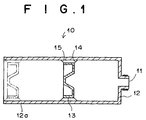
- an ink container 10 in accordance with an embodiment of the present invention comprises a cylinder 12 which is substantially cylindrical in shape and has an ink discharge port 11 in the front end face thereof, and a piston 13 which is fitted in the cylinder 12 to be slidable along the inner side surface 12a of the cylinder 12 toward the ink discharge port 11.
- Ink is contained in the space in the cylinder 12 between the front end face and the piston 13.
- the piston 13 is provided with an annular ink scraper portion 14 and an annular piston support portion 15 which extend radially outward from the rim of the piston 13 at the leading end and the trailing end thereof.
- the ink scraper portion 14 is in a close contact with the inner surface of the side wall of the cylinder 12 to form a tightly closed space between the cylinder 12 and the piston 13.
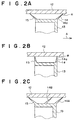
- the surface 14a of the ink scraper portion 14 in contact with the ink makes an angle R not smaller than 90° to the inner surface of the side wall of the cylinder 12 as measured toward the ink discharge port 11 from the surface 14a toward the ink discharge port 11.
- arrow A indicates the direction in which the piston 13 is moved (toward the ink discharge port 11).
- the piston 13 is moved toward the ink discharge port 11 under the atmospheric pressure as the ink is discharged through the ink discharge port 11 and the remainder of the ink in the ink container 10 becomes smaller while the ink scraper portion 14 scrapes ink off the inner surface of the side wall of the cylinder 12.
- the angle R between the surface 14a of the ink scraper portion 14 and inner surface of the cylinder 12 may be any angle not smaller than 90° and may be just 90° as shown in Figure 2B. Further, if desired, a pair of ink scraper portions 14A and 14B may be provided on the piston 13 as shown in Figure 2C.
- the cylinder 12 and the piston 13 may be formed of any material though it should be selected taking into account chemical resistance to the components of the ink, change in size of the cylinder 12 and the piston 13 due to swelling by the components of the ink, preservation of the ink, sliding friction between the cylinder 12 and the piston 13, flexibility of the ink scraper portion 14, and the like.
- the cylinder 12 and the piston 13 may be formed by injection molding of plastic material such as polypropylene (pp), high-density polyethylene (HDPE), polyvinyl chloride (PVC), polyethylene terephthalate (PET), polycarbonate (PC), polyoxymethylene (POM), polysulfone (PSF), polyether sulfone (PES), polyacrylate (PAR), polyamide (PA) and the like.
- plastic material such as polypropylene (pp), high-density polyethylene (HDPE), polyvinyl chloride (PVC), polyethylene terephthalate (PET), polycarbonate (PC), polyoxymethylene (POM), polysulfone (PSF), polyether sulfone (PES), polyacrylate (PAR), polyamide (PA) and the like.
- plastic material such as polypropylene (pp), high-density polyethylene (HDPE), polyvinyl chloride (PVC), polyethylene terephthalate (PET), polycarbonate (PC),
- the ink scraper portion 14 and the piston support portion 15 be formed of polypropylene (pp) or high-density polyethylene (HDPE) since they are preferably formed of flexible material. It is preferred that the ink scraper portion 14 and the piston support portion 15 be formed larger in the outer diameter than the inner diameter of the cylinder 12 so that they are pressed against the inner surface of the cylinder 12 under their own resiliency.
- the cylinder 12 and the piston 13 need not be formed of plastic but may be formed of other materials such as paper permeable to light.
- the cylinder 12 and the piston 13 are sized so that resistance generated by friction between the cylinder 12 and the piston 13 when the piston 13 is slid toward the ink discharge port 11 with the ink container 10 held empty is not lower than 1.0N (more preferably not lower than 2.5N. With this arrangement, generation of unsatisfactory ink scraping can be avoided.
- the resistance can be not smaller than 1.0N by setting the inner diameter of the cylinder 12 to 76.3 ⁇ 0.05mm (76.3mm in average) and setting the outer diameter of the piston 13 (including the ink scraper portion 14 and the piston support portion 15) as measured before the piston 13 is inserted into the cylinder 12 to at least 76.6mm.
- the resistance can be not smaller than 2.5N by setting the inner diameter of the cylinder 12 to 76.3mm and setting the outer diameter of the piston 13 as measured before the piston 13 is inserted into the cylinder 12 to at least 76.9mm.
- ink adhering to the inner surface of the side wall of the cylinder 12 can be well scraped off by the piston 13, whereby the events that the residual ink on the inner surface of the cylinder 12 deteriorates the light transmission of the cylinder 12 and adversely affects detection of the remainder of ink in the ink container 10, or the ink left on the inner surface of the empty container 10 mixes in the product when the ink containers are recycled to reuse them to another plastic product can be avoided. Further, ink in the ink container 10 can be fully used without running to waste.
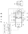
- FIG. 3 shows a stencil printer employing the ink container 10.
- the stencil printer comprises a printing mechanism 30 which prints on printing media (not shown) such as printing paper, transparent sheets for an OHP and the like and of a known structure including a printing drum, a sheet conveyance mechanism and the like; the ink container 10; an ink remainder detection control board 21 which concerns with detection of the remainder of the ink; and a general control board 22 for controlling the overall stencil printer.
- printing media such as printing paper, transparent sheets for an OHP and the like and of a known structure including a printing drum, a sheet conveyance mechanism and the like
- the ink container 10 an ink remainder detection control board 21 which concerns with detection of the remainder of the ink
- a general control board 22 for controlling the overall stencil printer.
- the printing mechanism 30 is of a known structure, the printing mechanism 30 will not be described here.
- the ink container 10 is filled with ink 16.
- a photodetector 20 is held by a board 23 in the rear end portion of the cylinder 12.
- the photodetector 20 is preferably a photoelectric convertor such as a phototransistor or a photodiode which outputs an electric signal upon receipt of light.
- the photodetector 20 is a phototransistor.
- first to third LEDs 1 to 3 are disposed.
- the position P1 is a position where the piston 13 is positioned when the remainder of the ink 16 in the ink container 12 is 10%, and in this particular embodiment, three first LEDs 1 (1-1, 1-2, 1-3) are disposed in the position P1 at regular intervals (at 120° ) in the circumferential direction of the cylinder 12.
- the position P2 is a position where the piston 13 is positioned when the remainder of the ink 16 in the ink container 12 is 30%, and in this particular embodiment, only one second LED 2 is disposed in the position P2.
- the position P3 is a position where the piston 13 is positioned when the remainder of the ink 16 in the ink container 12 is 50%, and in this particular embodiment, a pair of third LEDs 3 (3-1, 3-2) are disposed in the position P3 at regular intervals (at 180°) in the circumferential direction of the cylinder 12.
- each of the LEDs 1, 2 and 3 Light emitted from each of the LEDs 1, 2 and 3 is received by the photodetector 20 after once passing through the side wall of the cylinder 12 so long as no ink exists in the part of the ink container 12 opposed to the LED. Whereas when there remains ink 16 in the part of the ink container 12 opposed to the LED, light emitted from the LED is cut by the ink 16 and cannot impinge upon the photodetector 20. At this time, output of the photodetector 20 is 0 or very small.
- the ink 16 can be sometimes left on the inner side surface 12a of the cylinder 12 in a stripe pattern, which can cut the light emitted from the LED even there remains no ink 16 in part of the ink container 12 opposed to the LED.
- the positions P1 and P3 since there are disposed a plurality of LEDS, the light emitted from all the LEDs will not be cut by the stain of ink.
- the LEDs are turned on and off under the control of the ink remainder detection control board 21.
- the three first LEDs 1 (1-1, 1-2 and 1-3) in the position P1 are turned on simultaneously and the pair of third LEDs 3 (3-1 and 3-2) in the position P3 are turned on simultaneously.
- the remainder of the ink is detected in the following manner. All the first LEDs 1 (1-1, 1-2, 1-3) are first turned on, and the output signal of the photodetector 20 is detected. That is, whether the remainder of the ink in the container 10 is not larger than 10% is detected.
- the first LEDs 1 (1-1, 1-2, 1-3) are turned off and the second LED 2 is turned on, and the output signal of the photodetector 20 is detected. That is, whether the remainder of the ink in the container 10 is not larger than 30% is detected.
- the second LED 2 is turned off and the third LEDs 3-1 and 3-2 are turned on, and the output signal of the photodetector 20 is detected. That is, whether the remainder of the ink in the container 10 is not larger than 50% is detected.
- the remainder of the ink 16 in the ink container 10 is logically determined on the basis of the results of the three detections of the output signal of the photodetector 20. That is, when the output signal of the photodetector 20 is detected in all the three detections, i.e., when the photodetector 20 receives light from all the first to third LEDs, it is determined that the remainder of the ink 16 is not larger than 10%.
- the output signal of the photodetector 20 is detected in only the second and third detections, i.e., when the photodetector 20 receives light from only the second and third LEDS, it is determined that the remainder of the ink 16 is not smaller 10% and not larger than 30%.
- the output signal of the photodetector 20 is detected in only the third detection, i.e., when the photodetector 20 receives light from only the third LEDs, it is determined that that the remainder of the ink 16 is not smaller 30% and not larger than 50%.
- the output signal of the photodetector 20 is detected in none of the first to third detections, i.e., when the phototransistor 20 receives light from none of the first to third LEDs, it is determined that the remainder of the ink 16 is larger than 50%.
- the remainder of the ink 16 thus determined is temporarily stored in a memory (not shown).
- the ink remainder can be detected in this manner, it can be judged on the basis of the remainder of ink whether the ink container 12 is to be replaced by a new refill or whether the ink container 12 is to be replenished with ink. For example, when it has been known that a number of copies are to be printed in the next printing, it can be judged that one or more refills should be prepared even though more than 50% of ink remains in the ink container 12.
- ink container 10 of this embodiment generation of unsatisfactory ink scraping is prevented, and accordingly, light projected from the LEDs can be surely received by the photodetector 20 without blocked by ink left on the inner surface of the cylinder 12, whereby the ink remainder can be accurately detected.
- the color of ink, the wavelength of the emitted from the light projecting means, and the like need not be limited to a particular range. Further, it is possible to improve accuracy in detecting the ink remainder by increasing light collecting efficiency, for instance, by disposing a light condenser means such as a condenser lens in front of the photodetector or by using a photodetector having a larger light receiving face.
- a light condenser means such as a condenser lens
- the coefficient a is empirically obtained on the basis of the relation between the output voltage of the photodetector 20 and the gross transmittance of the side wall of the cylinder 12. For example, light is received by the photodetector 20 through side walls of the cylinder having different degrees of stain and the output voltages of the photodetector 20 are detected and plotted against transmittances of the side wall of the cylinder 12. Then the inclination of a straight line representing the plot is taken as the coefficient a . This will be described in more detail later.
- the term "minimum output voltage of the photodetector" should be interpreted to be the minimum voltage that a detecting means for detecting the output voltage of the photodetector 20, e.g., an ink remainder detecting circuit in the ink remainder detection control board 21 shown in Figure 2, can detect.
- the detecting means can detect the ink remainder when the voltage output from the photodetector 20 reaches a predetermined value, which varies depending upon the performance of the detecting means 20.
- Cylinder samples SP of different transmittances were prepared.
- the cylinder samples SP were 0%, 4%, 6%, 12% and 21%, respectively, in net transmittance to light at 900nm as measured by the use of Spectrophotometer V-570:Integrating Sphere Unit (manufactured by JASCO corporation).
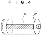
- black paper strips 40 Figure 4 which were 25%, 50%, 75% and 100% of the side surface of the cylinder 12 in area were prepared. All the paper strips 40 were of the same length as the cylinder 12 taking into account the fact that the ink can drag along the longitudinal axis of the cylinder to adhere to the inner surface of the side wall of the cylinder 12.
- One of the cylinders of each transmittance was attached with no paper strip and the other cylinders of each transmittance was attached with the black paper strips 40 of 25%, 50%, 75% and 100% of the side surface of the cylinder 12 (corresponding to 25%, 50%, 75% and 100% inner surface stain degrees) with their longitudinal axes extending in parallel to the side rib of the cylinder sample SP, along which ink was apt to be left.
- the cylinder samples SP in this state were set to the printer shown in Figure 3, and the output voltage of the photodetector 20 was measured.
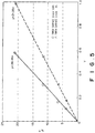
- Figure 5 shows the relation between the output voltage (V) of the photodetector 20 (x-axis) and the gross transmittance of the cylinder samples SP (y-axis) for 0% inner surface stain and 100% inner surface stain.
- V output voltage
- x-axis the output voltage of the photodetector 20
- SP gross transmittance of the cylinder samples SP
- the gross transmittance of the side wall of the cylinder is 5.4%T.
- V output voltage
- the color of ink, the wavelength of the emitted from the light projecting means, and the like need not be limited to a particular range. Further, it is possible to improve accuracy in detecting the ink remainder by increasing light collecting efficiency, for instance, by disposing a light condenser means such as a condenser lens in front of the photodetector or by using a photodetector having a larger light receiving face.
- a light condenser means such as a condenser lens
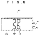
- the piston support portion 15 is annular in shape. However, when the piston support portion 15 is annular, the ink accidentally entering the space between the ink scraper portion 14 and the piston support portion 15 can be dragged along the longitudinal axis of the cylinder by the piston support portion 15 to stain the inner surface of the side wall of the cylinder 12 in a strip-like or stripe pattern.
- the piston support portion 15 be discontinuous as shown in Figures 7A to 7D.
- the piston support portion 15 may be in the form of a plurality of projections extending in a direction parallel to the longitudinal axis of the cylinder 12 as shown in Figure 7A.
- a plurality of notches 52 may be formed on an annular piston support portion 15 as shown in Figures 7B and 7C.
- the notches 52 shown in Figure 7B are shallow and partly cut the support portion 15, whereas the notches 52 shown in Figure 7C are deep and cut the support portion 15 to the root thereof.
- the annular piston support portion 15 may be cut to form a plurality of slits 53 as shown in Figure 7D.
- the ink container of the present invention may be incorporated in a printer where the ink remainder is detected by projecting light onto the cylinder from one side thereof and receiving light passing through the cylinder on the other side thereof.
Landscapes
- Ink Jet (AREA)
- Inking, Control Or Cleaning Of Printing Machines (AREA)
- Containers And Packaging Bodies Having A Special Means To Remove Contents (AREA)
- Pens And Brushes (AREA)
Abstract
Description
resistance generated by friction between the cylinder and the piston when the piston is slid toward the ink discharge port with the ink container held empty is not lower than 1.0N.
| No. | N | evaluation |
| #1 | 5.1 | □ |
| #2 | 5.7 | □ |
| #3 | 6.1 | □ |
| #4 | 5.4 | □ |
| #5 | 3.4 | □ |
| #6 | 3.1 | □ |
| #7 | 3.8 | ○ |
| #8 | 4.0 | ○ |
| #9 | 2.2 | ▵ |
| #10 | 2.1 | □ |
| #11 | 2.5 | ○ |
| #12 | 2.0 | □ |
| #13 | 0.4 | × |
| #14 | 0.3 | × |
| #15 | 1.0 | □ |
| #16 | 0.8 | × |
| net transmit. (%T) | output voltage (V) | |||||
| stain 0 | stain | 25% | stain 50% | stain 75% | stain 100% | |
| 21 | 0.994 | 0.800 | 0.713 | 0.710 | 0.586 | |
| 12 | 0.546 | 0.447 | 0.397 | 0.392 | 0.304 | |
| 6 | 0.301 | 0.250 | 0.219 | 0.217 | 0.162 | |
| 4 | 0.195 | 0.163 | 0.142 | 0.136 | 0.107 | |
| 0 | 0 | 0 | 0 | 0 | 0 |
Claims (15)
- An ink container comprising a cylinder provided with an ink discharge port at its leading end and a piston fitted in the cylinder to be slidable along the inner surface of the side wall of the cylinder so that ink is filled into the space defined by the cylinder and the piston, wherein the improvement comprises that
resistance generated by friction between the cylinder and the piston when the piston is slid toward the ink discharge port with the ink container held empty is not lower than 1.0N. - An ink container as defined in Claim 1 in which the resistance is not lower than 2.5N.
- An ink container as defined in Claim 1 in which at least one annular ink scraper portion is provided on the piston to extend radially outward so that its surface facing toward the ink discharge port makes an angle not smaller than 90° to the inner surface of the side wall of the cylinder as measured toward the ink discharge port from the surface facing toward the ink discharge port.
- An ink container as defined in Claim 1 in which a plurality of the pistons are fitted in the cylinder.
- An ink container as defined in Claim 1 incorporated in a printing device comprisinga photodetector which outputs an electric signal according to the amount of light the photodetector receives,a light projecting means which projects detecting light toward the photodetector through the side wall of the cylinder,and an ink remainder detecting means which detects the remainder of ink in the ink container on the basis of the electric signal output from the photodetector.
- An ink container as defined in Claim 5 in which the photodetector is disposed near the trailing end of the cylinder, a plurality of the light projecting means are provided in a plurality of different positions in the longitudinal direction of the cylinder and are turned on in different manners by position, and the ink remainder detecting means detects the remainder of ink in the ink container on the basis of change in the electric signal output from the photodetector.
- An ink container as defined in Claim 5 in which the resistance generated by friction between the cylinder and the piston when the piston is slid toward the ink discharge port with the ink container held empty is at least 2.5N at the portion where the light projecting means projects the detecting light.
- An ink container as defined in Claim 1 in which the gross transmittance y [%t] to light at 900nm of the side wall of the cylinder after ink is scraped off the inner surface of the side wall of the cylinder satisfies formula y=ax, wherein a is a coefficient not smaller than 21 and x represents a minimum output voltage of the photodetector.
- An ink container as defined in Claim 8 in which the coefficient a is not smaller than 36.
- An ink container as defined in Claim 8 in which a plurality of the pistons are fitted in the cylinder.
- An ink container as defined in Claim 8 in which the piston is provided with at least one annular ink scraper portion which extends radially outward from the piston and a piston support portion which extends radially outward from the piston to contact with the cylinder and support the piston in the cylinder.
- An ink container as defined in Claim 11 in which the piston support portion is in the form of at least one projection.
- An ink container as defined in Claim 11 in which the piston support portion is in the form of an annular member provided with a plurality of cutaway portions.
- An ink container as defined in Claim 8 incorporated in a printing device comprisinga photodetector which outputs an electric signal according to the amount of light the photodetector receives,a light projecting means which projects detecting light toward the photodetector through the side wall of the cylinder,and an ink remainder detecting means which detects the remainder of ink in the ink container on the basis of the electric signal output from the photodetector.
- An ink container as defined in Claim 14 in which the photodetector is disposed near the trailing end of the cylinder, a plurality of the light projecting means are provided in a plurality of different positions in the longitudinal direction of the cylinder and are turned on in different manners by position, and the ink remainder detecting means detects the remainder of ink in the ink container on the basis of change in the electric signal output from the photodetector.
Applications Claiming Priority (4)
| Application Number | Priority Date | Filing Date | Title |
|---|---|---|---|
| JP2000277238 | 2000-09-12 | ||
| JP2000277237A JP2002086678A (en) | 2000-09-12 | 2000-09-12 | Ink container |
| JP2000277237 | 2000-09-12 | ||
| JP2000277238A JP2002086679A (en) | 2000-09-12 | 2000-09-12 | Ink container |
Publications (3)
| Publication Number | Publication Date |
|---|---|
| EP1186423A2 true EP1186423A2 (en) | 2002-03-13 |
| EP1186423A3 EP1186423A3 (en) | 2002-12-18 |
| EP1186423B1 EP1186423B1 (en) | 2004-08-11 |
Family
ID=26599801
Family Applications (1)
| Application Number | Title | Priority Date | Filing Date |
|---|---|---|---|
| EP01121861A Expired - Lifetime EP1186423B1 (en) | 2000-09-12 | 2001-09-11 | Ink container |
Country Status (5)
| Country | Link |
|---|---|
| US (1) | US6572224B2 (en) |
| EP (1) | EP1186423B1 (en) |
| KR (1) | KR20020021043A (en) |
| CN (1) | CN1246153C (en) |
| DE (1) | DE60104785T2 (en) |
Families Citing this family (7)
| Publication number | Priority date | Publication date | Assignee | Title |
|---|---|---|---|---|
| US7861482B2 (en) * | 2006-07-14 | 2011-01-04 | Valinge Innovation Ab | Locking system comprising a combination lock for panels |
| CN101468542B (en) * | 2008-03-07 | 2011-04-13 | 谭慈源 | Papery environmental-protecting type vacuum printing ink container and printing ink-feeding device thereof |
| CN102490472B (en) * | 2011-12-14 | 2014-09-24 | 赫迎秋 | Automatic ink supply device, printing machine and printer |
| CN103707630B (en) * | 2014-01-15 | 2015-10-28 | 张彦粉 | A kind of container for draining ink and method |
| KR20200143115A (en) | 2019-06-14 | 2020-12-23 | 휴렛-팩커드 디벨롭먼트 컴퍼니, 엘.피. | Detecting toner injection amount of toner refill cartridge |
| US11298945B2 (en) * | 2019-08-27 | 2022-04-12 | Canon Kabushiki Kaisha | Liquid replenishing system |
| CN112406314B (en) * | 2020-09-18 | 2022-01-04 | 季华实验室 | Pressure accurate correction system and method and ink-jet printer |
Family Cites Families (5)
| Publication number | Priority date | Publication date | Assignee | Title |
|---|---|---|---|---|
| JPS60204355A (en) * | 1984-03-30 | 1985-10-15 | Canon Inc | Ink container |
| JP3015165B2 (en) * | 1991-08-30 | 2000-03-06 | キヤノン株式会社 | INK CONTAINER, PRINT HEAD UNIT USING THE SAME, AND PRINTING APPARATUS MOUNTING THE SAME |
| JPH05318756A (en) * | 1992-05-22 | 1993-12-03 | Canon Inc | Ink container |
| JP3185849B2 (en) * | 1995-08-23 | 2001-07-11 | セイコーエプソン株式会社 | Ink tank |
| JP3385593B2 (en) * | 2000-05-22 | 2003-03-10 | 理想科学工業株式会社 | Printing equipment |
-
2001
- 2001-09-11 DE DE60104785T patent/DE60104785T2/en not_active Expired - Lifetime
- 2001-09-11 EP EP01121861A patent/EP1186423B1/en not_active Expired - Lifetime
- 2001-09-12 US US09/949,620 patent/US6572224B2/en not_active Expired - Lifetime
- 2001-09-12 CN CNB011384387A patent/CN1246153C/en not_active Expired - Lifetime
- 2001-09-12 KR KR1020010056061A patent/KR20020021043A/en not_active Withdrawn
Also Published As
| Publication number | Publication date |
|---|---|
| EP1186423B1 (en) | 2004-08-11 |
| US20020054193A1 (en) | 2002-05-09 |
| DE60104785T2 (en) | 2004-12-30 |
| CN1246153C (en) | 2006-03-22 |
| KR20020021043A (en) | 2002-03-18 |
| US6572224B2 (en) | 2003-06-03 |
| CN1343566A (en) | 2002-04-10 |
| EP1186423A3 (en) | 2002-12-18 |
| DE60104785D1 (en) | 2004-09-16 |
Similar Documents
| Publication | Publication Date | Title |
|---|---|---|
| EP1157843B1 (en) | Printer | |
| EP1186423B1 (en) | Ink container | |
| US20090322836A1 (en) | Ink cartridges | |
| US20110310198A1 (en) | Image printing apparatus | |
| US20240198686A1 (en) | Liquid cartridge capable of reducing leakage of liquid from liquid storage chamber | |
| EP2397333B1 (en) | Ink cartridge and recording apparatus | |
| US20100085398A1 (en) | Ink surface detecting systems and ink cartridge | |
| EP2397330A1 (en) | Recording apparatus and ink cartridge | |
| JP2002370350A (en) | Environmental factor detection system for ink jet printing | |
| EP3659809B1 (en) | Recording apparatus comprising means to detect ink accumulation on an ink absorber and method thereof | |
| US10493749B2 (en) | Inkjet printing apparatus | |
| EP2397329B1 (en) | Recording apparatus and ink cartridge | |
| KR20030097712A (en) | Ink cartridge | |
| EP2397332B1 (en) | Ink cartridge and recording apparatus | |
| EP2147792A1 (en) | Container arrangement | |
| JP2002086678A (en) | Ink container | |
| EP2335928B1 (en) | Adapter for ink cartridge | |
| US5978104A (en) | Sheet discharge mechanism and apparatus incorporating the same | |
| EP2147794A1 (en) | Adapter for ink cartridge | |
| JP7534712B2 (en) | Image forming device | |
| US9884496B1 (en) | System for detecting contamination on decurler rollers in aqueous ink printers | |
| US11209303B2 (en) | Filling level detection in a printing fluid waste container | |
| JP2024158696A (en) | Image forming system | |
| JP2008207430A (en) | Fluid ejecting apparatus and operation method in fluid ejecting apparatus | |
| JP2004188630A (en) | Liquid ejection cartridge |
Legal Events
| Date | Code | Title | Description |
|---|---|---|---|
| PUAI | Public reference made under article 153(3) epc to a published international application that has entered the european phase |
Free format text: ORIGINAL CODE: 0009012 |
|
| 17P | Request for examination filed |
Effective date: 20010921 |
|
| AK | Designated contracting states |
Kind code of ref document: A2 Designated state(s): AT BE CH CY DE DK ES FI FR GB GR IE IT LI LU MC NL PT SE TR |
|
| AX | Request for extension of the european patent |
Free format text: AL;LT;LV;MK;RO;SI |
|
| PUAL | Search report despatched |
Free format text: ORIGINAL CODE: 0009013 |
|
| AK | Designated contracting states |
Kind code of ref document: A3 Designated state(s): AT BE CH CY DE DK ES FI FR GB GR IE IT LI LU MC NL PT SE TR |
|
| AX | Request for extension of the european patent |
Free format text: AL;LT;LV;MK;RO;SI |
|
| 17Q | First examination report despatched |
Effective date: 20030516 |
|
| AKX | Designation fees paid |
Designated state(s): DE GB |
|
| GRAP | Despatch of communication of intention to grant a patent |
Free format text: ORIGINAL CODE: EPIDOSNIGR1 |
|
| GRAS | Grant fee paid |
Free format text: ORIGINAL CODE: EPIDOSNIGR3 |
|
| GRAA | (expected) grant |
Free format text: ORIGINAL CODE: 0009210 |
|
| AK | Designated contracting states |
Kind code of ref document: B1 Designated state(s): DE GB |
|
| REG | Reference to a national code |
Ref country code: GB Ref legal event code: FG4D |
|
| REG | Reference to a national code |
Ref country code: IE Ref legal event code: FG4D |
|
| REF | Corresponds to: |
Ref document number: 60104785 Country of ref document: DE Date of ref document: 20040916 Kind code of ref document: P |
|
| PLBE | No opposition filed within time limit |
Free format text: ORIGINAL CODE: 0009261 |
|
| STAA | Information on the status of an ep patent application or granted ep patent |
Free format text: STATUS: NO OPPOSITION FILED WITHIN TIME LIMIT |
|
| REG | Reference to a national code |
Ref country code: IE Ref legal event code: MM4A |
|
| 26N | No opposition filed |
Effective date: 20050512 |
|
| REG | Reference to a national code |
Ref country code: DE Ref legal event code: R082 Ref document number: 60104785 Country of ref document: DE Representative=s name: KLUNKER IP PATENTANWAELTE PARTG MBB, DE |
|
| PGFP | Annual fee paid to national office [announced via postgrant information from national office to epo] |
Ref country code: DE Payment date: 20200924 Year of fee payment: 20 Ref country code: GB Payment date: 20200929 Year of fee payment: 20 |
|
| REG | Reference to a national code |
Ref country code: DE Ref legal event code: R071 Ref document number: 60104785 Country of ref document: DE |
|
| REG | Reference to a national code |
Ref country code: GB Ref legal event code: PE20 Expiry date: 20210910 |
|
| PG25 | Lapsed in a contracting state [announced via postgrant information from national office to epo] |
Ref country code: GB Free format text: LAPSE BECAUSE OF EXPIRATION OF PROTECTION Effective date: 20210910 |