EP1186394A2 - Lattice gate for drop injection molding - Google Patents
Lattice gate for drop injection molding Download PDFInfo
- Publication number
- EP1186394A2 EP1186394A2 EP01120607A EP01120607A EP1186394A2 EP 1186394 A2 EP1186394 A2 EP 1186394A2 EP 01120607 A EP01120607 A EP 01120607A EP 01120607 A EP01120607 A EP 01120607A EP 1186394 A2 EP1186394 A2 EP 1186394A2
- Authority
- EP
- European Patent Office
- Prior art keywords
- gate
- drop
- rubber
- lattice
- flow channels
- Prior art date
- Legal status (The legal status is an assumption and is not a legal conclusion. Google has not performed a legal analysis and makes no representation as to the accuracy of the status listed.)
- Granted
Links
Images




Classifications
-
- B—PERFORMING OPERATIONS; TRANSPORTING
- B29—WORKING OF PLASTICS; WORKING OF SUBSTANCES IN A PLASTIC STATE IN GENERAL
- B29C—SHAPING OR JOINING OF PLASTICS; SHAPING OF MATERIAL IN A PLASTIC STATE, NOT OTHERWISE PROVIDED FOR; AFTER-TREATMENT OF THE SHAPED PRODUCTS, e.g. REPAIRING
- B29C45/00—Injection moulding, i.e. forcing the required volume of moulding material through a nozzle into a closed mould; Apparatus therefor
- B29C45/17—Component parts, details or accessories; Auxiliary operations
- B29C45/26—Moulds
- B29C45/27—Sprue channels ; Runner channels or runner nozzles
- B29C45/2701—Details not specific to hot or cold runner channels
-
- B—PERFORMING OPERATIONS; TRANSPORTING
- B29—WORKING OF PLASTICS; WORKING OF SUBSTANCES IN A PLASTIC STATE IN GENERAL
- B29C—SHAPING OR JOINING OF PLASTICS; SHAPING OF MATERIAL IN A PLASTIC STATE, NOT OTHERWISE PROVIDED FOR; AFTER-TREATMENT OF THE SHAPED PRODUCTS, e.g. REPAIRING
- B29C45/00—Injection moulding, i.e. forcing the required volume of moulding material through a nozzle into a closed mould; Apparatus therefor
- B29C45/17—Component parts, details or accessories; Auxiliary operations
- B29C45/26—Moulds
- B29C45/27—Sprue channels ; Runner channels or runner nozzles
- B29C45/2701—Details not specific to hot or cold runner channels
- B29C45/2708—Gates
-
- B—PERFORMING OPERATIONS; TRANSPORTING
- B29—WORKING OF PLASTICS; WORKING OF SUBSTANCES IN A PLASTIC STATE IN GENERAL
- B29K—INDEXING SCHEME ASSOCIATED WITH SUBCLASSES B29B, B29C OR B29D, RELATING TO MOULDING MATERIALS OR TO MATERIALS FOR MOULDS, REINFORCEMENTS, FILLERS OR PREFORMED PARTS, e.g. INSERTS
- B29K2021/00—Use of unspecified rubbers as moulding material
Definitions
- the present invention relates to an improved gate design for drop gate injection molding of rubber compounds to form rubber articles. More particularly, the present invention relates to the unexpected combination of a drop gate with a lattice gate for increased gate heating efficiency and reduced cycle time while the rubber part is being injection molded.
- uncured viscous elastomeric compound is introduced into an elongated barrel of an injection molding machine at ambient temperatures.
- the compound is advanced through the barrel towards a mold connected to the downstream end of the barrel, usually by either a rotating screw conveyor or a reciprocating ram or piston disposed in the barrel.
- a mold connected to the downstream end of the barrel, usually by either a rotating screw conveyor or a reciprocating ram or piston disposed in the barrel.
- the elastomeric compound advances, it is heated by heat conduction and mechanical shear heating in the barrel to reduce its viscosity and render the elastomer more flowable and amenable to subsequent injection into the mold.
- the less viscous the compound the more easily it flows through a conventional gate system and the more easily it fills a mold cavity to produce a satisfactorily molded object.
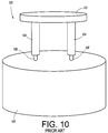
- FIG 10 is a schematic drawing of a drop gate design 100 used to mold an article.
- a sprue pad 102 feeds elastomer to drop gate runners 104. From the runners 104, the elastomer flows through the drop gate orifices 106, which have a smaller diameter than the drop gate runners 104, and fills the mold cavity 108.
- WO-A- 98/56559 discloses another gate design for injection molding rubber compounds.
- the gate design is a lattice gate.
- the lattice gate minimizes differences in temperature and pressure that result in a parabolic rubber flow through the gate. This is achieved by a series of crossed flow channels.
- WO-A- 98/56559 teaches replacement of the conventional flat gate of the prior art with the inventive lattice gate.
- the present invention is directed to an improved method and apparatus for a drop injection gate for molding rubber.
- the inventive method reduces curing time and improves the heat characteristics of the rubber as it is injected.
- One aspect of the invention is an improved method of drop gate injection molding rubber.
- the method comprising injecting a rubber into a drop gate and through drop gate runners and into a mold cavity. The rubber flows at cross angles after the rubber is injected into the gate and before the rubber enters into the drop gate runners.
- Another aspect of the invention is an improved drop injection gate for injection molding rubber into a mold cavity.
- the gate is comprised of drop gate runners.
- the gate has a region adjacent to the drop gate runners comprising a first and a second plurality of spaced flow channels disposed at intersecting angles to each other to create cross direction flow of the rubber before the rubber enters into the drop gate runners.
- the drop injection gate has more than one separate region adjacent to drop gate runners comprising the first and second plurality of spaced flow channels disposed at intersecting angles to each other.
- FIG. 1 is a schematic representation of the inventive hybrid gate system 2.
- the hybrid gate system 2 incorporates a lattice gate 4 after the sprue inlet 6. Elastomeric material flows into the hybrid gate 2 through the sprue inlet 6, and then flows through the lattice gate 4.
- An outlet distribution channel 8 from the lattice gate 4 feeds the elastomer from the lattice gate 4 to the drop gate runners 10. From the runners 10, the elastomer flows through the drop gate orifices 12 and fills the mold cavity 14.
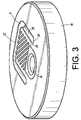
- FIGS 2 and 3 illustrate the bottom plate 16, also known as the gate plate. Offset from the center of the plate 16 is a distribution area 18. Adjacent to the distribution area 18 is a plurality of flow channels 20. At the opposing end of the flow channels 20 is a U-shaped outlet distribution channel 8. The U-shaped outlet distribution channel 8 has a central portion 22 coincident with the ends of the flow channels 20. At the terminal ends 24 of the side portions 26 of the outlet distribution channel 8 are ports 28 to the drop gate runners 10.
- the inclination direction of the channels 20, 34 is identical.
- the plurality of flow channels 20, 34 formed in the plates 16, 30 are parallel to each other and inclined at angles ⁇ of about 30° to about 70°, preferably at angles of about 45° to about 60°, with respect to a centerline 36.
- the angle ⁇ of the parallel flow channels 16, 30 increases with respect to the centerline 36 of each plate 16, 30, the time required for any elastomeric compound to flow through the channels 20, 34 also increases, and vice versa.
- the flow channels 20, 34 are illustrated with a semi-circular cross-section; however, it is within this invention to form the flow channels 20, 34 with other cross-sections, such as elliptical, triangular, or square as desired.
- FIGS. 5, 6, and 7 illustrate the lattice gate 4 after the top and bottom plates 16, 30 have been assembled.
- the sprue inlet bore 32 of the top plate 30 is aligned along a same axis with the drop gate ports 28, while being offset from the center of the distribution area 18 of the bottom plate 16.
- the plurality of flow channels 20, 34 are coincident with the edge of the distribution area 18 at one end, while the opposing end of the flow channels 20, 34 are coincident with the central portion 22 of the outlet distribution channel 8.
- the elastomeric compound flows into the lattice gate 4 through the sprue bore 32, the compound fills the distribution area 18 due to the injection pressure.
- the compound then flows into the cross directional flow channels 20, 34, exiting the flow channels 20, 34 into the central portion 22 of the outlet distribution channel 8.
- the injection pressure of the elastomer forces the compound to then flow through the side portions 26 of the outlet distribution channel 8 and through the drop gate runner ports 28.
- spacing must be maintained between the flow channels 20, 34 and the side portions 26 of the outlet distribution channel 8. If this spacing is insufficient, the elastomeric compound may not travel completely through the lattice gate 4, but it may enter the distribution channel 8 prior to complete mixing of the compound through the flow channels 20, 34. This spacing can be seen in FIG. 6.
- the distribution area 18 has a predominantly circular configuration and depth greater than the flow channels 20, 34 so that the injection pressure may be used to exert pressure on an essential component about which the elastomeric compound is to be molded; e.g. a central steel tube in a molded motor mount.
- the illustrated distribution area 18 is specific to a particular application.
- the shape of the distribution area 18 is designed to meet the needs of each specific molding application.
- the distribution area 18 of a bottom plate 38 may be configured as a single portion flow channel 18' connecting the sprue bore of the top plate to the flow channels 20, 34; such a variation is illustrated in FIG. 8.
- the outlet distribution channel 8 may have a configuration other than a U-shape.
- a U-shape outlet distribution channel addresses the need to have two spaced drop gate ports 28 feeding two drop gate runners 10. If the specific molding application or injection machine permits, the outlet distribution channel 8 may have another configuration, such as a straight line flow channel 8' with a central drop gate port 40, as illustrated in FIG. 8.
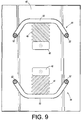
- FIG. 9 illustrates a configuration that may be employed for the bottom plate 42.
- the hybrid injection gate 2 has two separate lattice gates 44. Each lattice gate has a distribution area 46, flow channels 48, a distribution channel 50, and drop gate ports 52. Such a hybrid gate 2 permits the use of four drop gate runners 10 to feed to mold cavity 14.
- a 40-ton vertical injection molder was used for the test.
- the mold employed was a production engine mount mold with exchangeable top plates.
- the first set of top plates had a drop gate design delivery system only (schematically illustrated in FIG. 10).
- the second set of top plates had the lattice gate followed by an identical drop gate delivery system (schematically illustrated in FIG. 1).
- the drop gate design delivery system had a 0.229 cm (0.090") injection orifice.
- the lattice gate had a structure of 45/5/0.099cm/3.175cm (channel angle/number of channels/channel radius/length) (45/5/ 0.039"/1.25"), and had a construction similar to the lattice gate 4 illustrated in FIG. 5.
- the mold temperature was 154° to 163° C (310° to 325° F), depending upon the location within the mold.
- the rubber temperature at the time of injection was 127° to 130° C (260° to 265° F).
- the top plates with the lattice gate design were not treated with any release coatings.
- Engine mount bushings were injected on the 40-ton injector using bushing metals without adhesive to permit easy removal of the metal insert from the molded rubber.
- the rubber was cut open at the point of least cure.
- the size of the uncured region at the point of least cure gives a relative state of cure.
- the bushing was considered sufficiently cured if there was no sign of uncured or doughy rubber. While many of the parts that had uncured rubber inside immediately after injection would eventually have cured completely from the latent heat within the bushing, the intent of the comparative tests was to establish a baseline for comparison of the two gate designs. Thus, all comparisons were done by cutting the part open immediately after removal from the mold.
- Part No. 5 the bushing was almost completely cured at 60 seconds, but rubber porosity occurred at the interface between the smaller metal insert and the rubber.
- the metal insert acted as a heat sink, cooling the rubber at its surface and slowing the cure rate.
- a conservative estimate for Part No. 5's minimum cure time can be estimated at 90 seconds, this being extrapolated from the 60 second and 120 second cure times although the actual minimum cure time could be closer to 60 seconds.
- Part Nos 1 to 5 the injection time may be reduced by the use of release coatings on the lattice gate plates.
- the use of the lattice gate in combination with the drop gate reduced the part cure time from 360 seconds to 90 seconds (see above discussion), the total cycle time for the part from 365 to 108 seconds. This is a 75% reduction in cure time and a reduction of over 70% in the total cycle time. Even if the minimum cure time for Part No. 5 is not extrapolated out to 90 seconds and the cure time of Part No. 4 is used instead to determine the cure time improvement, the cure time for Part No. 4 is reduced by 66%, and total cycle time is reduced by over 60%.
- the hybrid injection gate is more efficient in heating the rubber prior to the rubber entering the mold cavity. This can be clearly seen by the substantially reduced cure times of the trial runs.
- Using the hybrid concept permits the incorporation of the lattice gate into the gate design where the known plane of entry lattice gate design alone could not be used.
- the flow from the lattice gate is instead channeled through outlet distribution channels acting as mold runners to move the rubber to the drop gate and into the mold cavity.
- the present invention of incorporation of a lattice gate with a drop gate is capable of reducing cure times required to mold parts. Such reduced cure times are especially beneficial for molded parts with very thick cross-sections.
- the mixing of the molding compound as it flows through the channeled entry lattice gate also improves the mixing and temperature uniformity of the molding compound prior to entry of the compound into the mold.
Landscapes
- Engineering & Computer Science (AREA)
- Manufacturing & Machinery (AREA)
- Mechanical Engineering (AREA)
- Moulds For Moulding Plastics Or The Like (AREA)
- Injection Moulding Of Plastics Or The Like (AREA)
- Heating, Cooling, Or Curing Plastics Or The Like In General (AREA)
Abstract
Description
| Comparison Cure Times | ||||||
| Part No. | Gate Type | Injection time (seconds) | Cure Time (seconds) | Total Cycle time | Completely Cured? | Comments |
| 1 | | 18 | 270 | 298 | Yes | Fully cured |
| 2 | | 18 | 240 | 258 | Yes | Fully cured |
| 3 | | 18 | 180 | 198 | Yes | Fully cured |
| 4 | | 18 | 120 | 138 | Yes | Fully cured |
| 5 | | 18 | 60 | 78 | No | Part looks fully cured, point of least cure occurring at |
| 6 | drop | 5 | 360 | 365 | Yes | ~1/2"- 3/4"D glossy spot but no dough |
| 7 | | 6 | 300 | 306 | No | Process conditioning part, but had ~1" x 3/4" uncured area |
Claims (3)
- A method of drop gate injection molding rubber, the method comprising injecting a rubber into a drop gate (12), through drop gate runners (10) and into a mold cavity (14), the method being characterized by the rubber flowing at cross angles after the rubber is injected into the gate and before the rubber enters into the drop gate runners (10).
- A drop injection gate (2) for injection molding rubber into a mold cavity (14), the gate comprising drop gate runners (10), the gate being characterized by the gate having a region adjacent to the drop gate runners (10) comprising a first and a second plurality of spaced flow channels (20, 34) disposed at intersecting angles to each other to create cross direction flow of the rubber before the rubber enters into the drop gate runners.
- The drop injection gate (2) in accordance with claim 2 wherein more than one separate regions adjacent to drop gate runners (10) comprise the first and second plurality of spaced flow channels (20, 34) disposed at intersecting angles to each other.
Applications Claiming Priority (2)
| Application Number | Priority Date | Filing Date | Title |
|---|---|---|---|
| US09/658,087 US6607688B1 (en) | 2000-09-08 | 2000-09-08 | Lattice gate for drop gate injection molding |
| US658087 | 2000-09-08 |
Publications (3)
| Publication Number | Publication Date |
|---|---|
| EP1186394A2 true EP1186394A2 (en) | 2002-03-13 |
| EP1186394A3 EP1186394A3 (en) | 2003-10-08 |
| EP1186394B1 EP1186394B1 (en) | 2005-02-09 |
Family
ID=24639843
Family Applications (1)
| Application Number | Title | Priority Date | Filing Date |
|---|---|---|---|
| EP01120607A Expired - Lifetime EP1186394B1 (en) | 2000-09-08 | 2001-08-29 | Lattice gate for drop injection molding |
Country Status (8)
| Country | Link |
|---|---|
| US (2) | US6607688B1 (en) |
| EP (1) | EP1186394B1 (en) |
| JP (1) | JP2002096357A (en) |
| CN (1) | CN1161217C (en) |
| BR (1) | BR0103857A (en) |
| CA (1) | CA2354124A1 (en) |
| DE (1) | DE60108822T2 (en) |
| MX (1) | MXPA01008710A (en) |
Families Citing this family (6)
| Publication number | Priority date | Publication date | Assignee | Title |
|---|---|---|---|---|
| CA2354319A1 (en) * | 2000-09-08 | 2002-03-08 | The Goodyear Tire & Rubber Company | Runner for injection molding |
| US6857462B2 (en) * | 2002-11-25 | 2005-02-22 | Honda Giken Kogyo Kabushiki Kaisha | High pressure die cast process |
| US20090087509A1 (en) * | 2005-04-15 | 2009-04-02 | Miguel Linares | Multi-gate reaction injection assembly for use with a closed mold for mixing and setting iso and poly fluid based polymers & plastics with one or more aggregate filler materials |
| US7988903B2 (en) * | 2008-07-02 | 2011-08-02 | Zeon Chemicals L.P. | Fast curing vulcanizable multi-part elastomer composition, and process for blending, injection molding and curing of elastomer composition |
| TW201233521A (en) * | 2011-02-01 | 2012-08-16 | Quanta Comp Inc | Plastic material injection molding system |
| CN113001875B (en) * | 2021-02-03 | 2021-12-17 | 江苏远祥新材料有限公司 | A kind of composite plastic Fang intelligent production equipment and its production process |
Family Cites Families (11)
| Publication number | Priority date | Publication date | Assignee | Title |
|---|---|---|---|---|
| US2426651A (en) * | 1946-03-04 | 1947-09-02 | French Oil Mill Machinery | Injection molding |
| AT351243B (en) * | 1973-09-14 | 1979-07-10 | Demag Kunststofftech | GATE DEVICE FOR CASTING FORMS FOR THE PRODUCTION OF OBJECTS FROM PLASTICS FORMING FROM MULTIPLE LIQUID COMPONENTS |
| GB1570853A (en) * | 1975-02-19 | 1980-07-09 | Pirelli | Mehtod and apparatus for the injection moulding of pneumatic tyres |
| US3989434A (en) * | 1975-10-29 | 1976-11-02 | Mcdowell-Wellman Engineering Company | Blending and molding means |
| US4199315A (en) * | 1976-02-19 | 1980-04-22 | Industrie Pirelli S.P.A. | Apparatus for the injection molding of pneumatic tires having symmetrical parts of similar physical characteristics |
| JPH0337931Y2 (en) * | 1986-04-30 | 1991-08-12 | ||
| US5804231A (en) | 1996-12-23 | 1998-09-08 | General Motors Corporation | Expandable hot runner manifold |
| US6379603B1 (en) * | 1997-06-09 | 2002-04-30 | The Goodyear Tire & Rubber Company | Lattice gate for injection molding of rubber compounds |
| DE69708161T2 (en) | 1997-06-09 | 2002-06-20 | The Goodyear Tire & Rubber Co., Akron | GRILLING FOR INJECTION MOLDING OF RUBBER BLENDS |
| DE69827834T2 (en) * | 1997-10-14 | 2005-12-08 | The Penn State Research Foundation | METHOD AND DEVICE FOR BALANCING THE FILLING OF SPRAY FORMS |
| US6387313B1 (en) * | 1999-12-15 | 2002-05-14 | The Goodyear Tire & Rubber Company | Gate for injection molding rubber compounds |
-
2000
- 2000-09-08 US US09/658,087 patent/US6607688B1/en not_active Expired - Fee Related
-
2001
- 2001-07-26 CA CA002354124A patent/CA2354124A1/en not_active Abandoned
- 2001-08-28 MX MXPA01008710A patent/MXPA01008710A/en active IP Right Grant
- 2001-08-29 EP EP01120607A patent/EP1186394B1/en not_active Expired - Lifetime
- 2001-08-29 DE DE60108822T patent/DE60108822T2/en not_active Expired - Fee Related
- 2001-09-03 BR BR0103857-5A patent/BR0103857A/en not_active Application Discontinuation
- 2001-09-07 CN CNB011325895A patent/CN1161217C/en not_active Expired - Fee Related
- 2001-09-07 JP JP2001271598A patent/JP2002096357A/en active Pending
-
2003
- 2003-05-30 US US10/449,551 patent/US6821111B2/en not_active Expired - Fee Related
Also Published As
| Publication number | Publication date |
|---|---|
| BR0103857A (en) | 2002-05-07 |
| EP1186394B1 (en) | 2005-02-09 |
| DE60108822D1 (en) | 2005-03-17 |
| JP2002096357A (en) | 2002-04-02 |
| CA2354124A1 (en) | 2002-03-08 |
| CN1343559A (en) | 2002-04-10 |
| US6821111B2 (en) | 2004-11-23 |
| US6607688B1 (en) | 2003-08-19 |
| CN1161217C (en) | 2004-08-11 |
| EP1186394A3 (en) | 2003-10-08 |
| MXPA01008710A (en) | 2002-04-10 |
| US20030206992A1 (en) | 2003-11-06 |
| DE60108822T2 (en) | 2006-01-19 |
Similar Documents
| Publication | Publication Date | Title |
|---|---|---|
| CN109514889B (en) | Cordwood fiber dipping die capable of being assembled | |
| DE69008894T2 (en) | Injection molding device with gas flow through the valve opening. | |
| US6863729B2 (en) | Nozzle insert for long fiber compounding | |
| CA1148315A (en) | Method and apparatus for runnerless injection-compression molding thermosetting materials | |
| AU7715498A (en) | Injection molding shut-off bushing with separate material flow path | |
| EP1186394B1 (en) | Lattice gate for drop injection molding | |
| JP2004520189A (en) | Flow deflector device and use thereof | |
| EP0447573B1 (en) | Hot runner nozzle | |
| EP1979151B1 (en) | Improved neck block cooling | |
| JP7338878B2 (en) | Method and tool for injection molding | |
| US6796786B2 (en) | Runner for injection molding | |
| EP0240753B1 (en) | Method and apparatus for producing moulded plastic articles | |
| US6387313B1 (en) | Gate for injection molding rubber compounds | |
| EP1009611B1 (en) | Lattice gate for injection molding of rubber compounds | |
| US6379603B1 (en) | Lattice gate for injection molding of rubber compounds | |
| CN115157711A (en) | Long fiber thermoplastic molding process | |
| JP5860058B2 (en) | Mold tool system having a manifold body defining an unbroken melt channel | |
| DE10013920A1 (en) | Injection molding system for elastomers comprises injector for vulcanisable elastomer and heated molding section, channel which feeds elastomer to molds having block of insulating material with central bore mounted at its top | |
| DE202008000610U1 (en) | Apparatus for the production of glass fiber reinforced plastics | |
| CN120481209B (en) | Hot runner multipoint injection mold and injection molding method | |
| JPS5863428A (en) | Injection molding method for thermoplastic resin and split die mold for injection molding | |
| CN205735846U (en) | A kind of three-plate type can process the pouring gate structure of plastic elbow mould | |
| DE202023106358U1 (en) | Injection molding tool | |
| EP4549125A1 (en) | Nozzle insert and nozzle for an injection moulding tool | |
| CN1256660A (en) | Lattice gate for injection molding of rubber compounds |
Legal Events
| Date | Code | Title | Description |
|---|---|---|---|
| PUAI | Public reference made under article 153(3) epc to a published international application that has entered the european phase |
Free format text: ORIGINAL CODE: 0009012 |
|
| AK | Designated contracting states |
Kind code of ref document: A2 Designated state(s): AT BE CH CY DE DK ES FI FR GB GR IE IT LI LU MC NL PT SE TR |
|
| AX | Request for extension of the european patent |
Free format text: AL;LT;LV;MK;RO;SI |
|
| PUAL | Search report despatched |
Free format text: ORIGINAL CODE: 0009013 |
|
| AK | Designated contracting states |
Kind code of ref document: A3 Designated state(s): AT BE CH CY DE DK ES FI FR GB GR IE IT LI LU MC NL PT SE TR |
|
| AX | Request for extension of the european patent |
Extension state: AL LT LV MK RO SI |
|
| 17P | Request for examination filed |
Effective date: 20040408 |
|
| AKX | Designation fees paid |
Designated state(s): DE FR GB IT |
|
| GRAP | Despatch of communication of intention to grant a patent |
Free format text: ORIGINAL CODE: EPIDOSNIGR1 |
|
| GRAS | Grant fee paid |
Free format text: ORIGINAL CODE: EPIDOSNIGR3 |
|
| GRAA | (expected) grant |
Free format text: ORIGINAL CODE: 0009210 |
|
| AK | Designated contracting states |
Kind code of ref document: B1 Designated state(s): DE FR GB IT |
|
| REG | Reference to a national code |
Ref country code: GB Ref legal event code: FG4D |
|
| REG | Reference to a national code |
Ref country code: IE Ref legal event code: FG4D |
|
| REF | Corresponds to: |
Ref document number: 60108822 Country of ref document: DE Date of ref document: 20050317 Kind code of ref document: P |
|
| ET | Fr: translation filed | ||
| PLBE | No opposition filed within time limit |
Free format text: ORIGINAL CODE: 0009261 |
|
| STAA | Information on the status of an ep patent application or granted ep patent |
Free format text: STATUS: NO OPPOSITION FILED WITHIN TIME LIMIT |
|
| 26N | No opposition filed |
Effective date: 20051110 |
|
| PGFP | Annual fee paid to national office [announced via postgrant information from national office to epo] |
Ref country code: DE Payment date: 20070831 Year of fee payment: 7 |
|
| PGFP | Annual fee paid to national office [announced via postgrant information from national office to epo] |
Ref country code: GB Payment date: 20070705 Year of fee payment: 7 |
|
| PGFP | Annual fee paid to national office [announced via postgrant information from national office to epo] |
Ref country code: IT Payment date: 20070813 Year of fee payment: 7 |
|
| PGFP | Annual fee paid to national office [announced via postgrant information from national office to epo] |
Ref country code: FR Payment date: 20070803 Year of fee payment: 7 |
|
| GBPC | Gb: european patent ceased through non-payment of renewal fee |
Effective date: 20080829 |
|
| REG | Reference to a national code |
Ref country code: FR Ref legal event code: ST Effective date: 20090430 |
|
| PG25 | Lapsed in a contracting state [announced via postgrant information from national office to epo] |
Ref country code: IT Free format text: LAPSE BECAUSE OF NON-PAYMENT OF DUE FEES Effective date: 20080829 Ref country code: FR Free format text: LAPSE BECAUSE OF NON-PAYMENT OF DUE FEES Effective date: 20080901 Ref country code: DE Free format text: LAPSE BECAUSE OF NON-PAYMENT OF DUE FEES Effective date: 20090303 |
|
| PG25 | Lapsed in a contracting state [announced via postgrant information from national office to epo] |
Ref country code: GB Free format text: LAPSE BECAUSE OF NON-PAYMENT OF DUE FEES Effective date: 20080829 |