EP1186382A2 - Steel stud crimper - Google Patents
Steel stud crimper Download PDFInfo
- Publication number
- EP1186382A2 EP1186382A2 EP01307754A EP01307754A EP1186382A2 EP 1186382 A2 EP1186382 A2 EP 1186382A2 EP 01307754 A EP01307754 A EP 01307754A EP 01307754 A EP01307754 A EP 01307754A EP 1186382 A2 EP1186382 A2 EP 1186382A2
- Authority
- EP
- European Patent Office
- Prior art keywords
- crimping apparatus
- cam
- jaw
- transmission mechanism
- jaw assembly
- Prior art date
- Legal status (The legal status is an assumption and is not a legal conclusion. Google has not performed a legal analysis and makes no representation as to the accuracy of the status listed.)
- Granted
Links
Images


Classifications
-
- B—PERFORMING OPERATIONS; TRANSPORTING
- B25—HAND TOOLS; PORTABLE POWER-DRIVEN TOOLS; MANIPULATORS
- B25B—TOOLS OR BENCH DEVICES NOT OTHERWISE PROVIDED FOR, FOR FASTENING, CONNECTING, DISENGAGING, OR HOLDING
- B25B27/00—Hand tools, specially adapted for fitting together or separating parts or objects whether or not involving some deformation, not otherwise provided for
- B25B27/14—Hand tools, specially adapted for fitting together or separating parts or objects whether or not involving some deformation, not otherwise provided for for assembling objects other than by press fit or detaching same
- B25B27/146—Clip clamping hand tools
-
- B—PERFORMING OPERATIONS; TRANSPORTING
- B21—MECHANICAL METAL-WORKING WITHOUT ESSENTIALLY REMOVING MATERIAL; PUNCHING METAL
- B21D—WORKING OR PROCESSING OF SHEET METAL OR METAL TUBES, RODS OR PROFILES WITHOUT ESSENTIALLY REMOVING MATERIAL; PUNCHING METAL
- B21D39/00—Application of procedures in order to connect objects or parts, e.g. coating with sheet metal otherwise than by plating; Tube expanders
- B21D39/03—Application of procedures in order to connect objects or parts, e.g. coating with sheet metal otherwise than by plating; Tube expanders of sheet metal otherwise than by folding
- B21D39/034—Joining superposed plates by piercing
Definitions
- the present invention relates generally to hand tools, and more particularly to a power tool for crimping steel studs and tracks during construction framing.
- Steel framing has become increasingly popular for residential and commercial buildings due to the increased strength and termite resistance of steel relative to wood.
- the process of assembling steel framing is time consuming and expensive relative to the material costs.
- steel framing has been slow to achieve wide-spread acceptance.
- Crimping tools have also been utilized to connect the studs to the tracks.
- manual crimping tools require a lot of strength and endurance to operate on large jobs and power crimping tools have proven to be heavy and cumbersome.
- the inefficiency of prior methods for assembling steel studs to the tracks has contributed greatly to the labor costs for steel frame construction.
- the present invention provides a crimping tool including a rotary drive unit and an extension arm.
- the extension arm includes a pivotally attached jaw assembly attached thereto.
- the gear configuration in the extension arm translates a rotary input into actuation of the jaw assembly.
- the jaw assembly includes a first piercing jaw arm and a second receiving jaw arm for cyclical engagement therewith.
- a logic circuit limits an activation to one complete crimping cycle of the jaw assembly.
- the crimp tool 10 of the present invention generally includes a rotary drive tool 12 and a crimp attachment 14.
- the rotary drive tool 12 includes an output shaft (not specifically shown) that is coupled to a rotary shaft 16 (Fig. 9) with a connecting device carried in an extension barrel 20 which also houses a transmission 18 (best shown in Figure 4).
- Power source 24 interconnects to drive tool 12.
- the barrel 20 is rotatable about its longitudinal axis and a jaw assembly 19 is coupled to the barrel 20 for pivotal movement relative thereto.
- the transmission 18 transfers the rotary motion of the rotary shaft 16 to articulate the jaws as hereinafter described.
- the jaw assembly 19 is coupled to pivot relative to the barrel 20 by a pivot shaft 26 to allow the laborer to move the jaw assembly 19 to a proper position prior to crimping.
- the crimp tool 10 permits the laborer to position the jaw assembly 19 to crimp both sides of the stud/track from the same side of the wall.
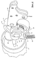
- the transmission 18 operatively couples the jaw assembly 19 to the rotary shaft 16 such that rotation of the shaft 16 causes pivotable movement of an upper jaw 28 about a pivot pin 30 fixed to a lower jaw 32.
- Rivet 81 holds the members that comprise the upper jaw arm 28 together and rivet 82 holds the members of the lower jaw arm 32 together.
- movement of the upper jaw 28 from its open position to its closed position causes a piercing bit 33 to deform the stud and frame thereby crimping the two members together.
- the surface of the lower jaw 32 that accommodates the piercing bit 33 may be configured to fold over the resulting burr thereby limiting the distance that the burr protrudes from the stud or track.
- transmission 18 includes a cam 34 fixed for rotation with rotary shaft 16, a rocker arm 36 having a first end 44 engaged with cam 34 and a second end 45 fixed to rotate with shaft 26.
- a counterweight 87 extends from shaft 16 to encourage smooth operation.
- the first end 44 includes a bearing 49 which acts as a cam follower to cam 34.
- Cam 34 is configured to have an eccentric surface 35 to engage bearing 49 in a common plane while rocker arm 36 rotates.
- a drive cam 40 is coupled to the shaft 26 by a roller clutch 38 (Fig. 6).
- the upper jaw 28 includes a cam follower 42 that engages drive cam 40 to displace the upper jaw 28 between its open and closed positions in response to rotation of the drive cam 40.
- the eccentric surface 35 of the cam 34 oscillates the first end 44 of the rocker arm 36 in pivoting motion about the axis 46 of shaft 26. More particularly, the riding engagement between the first end 44 of the rocker arm 36 and the rotating cam 34 causes cyclical displacement of the rocker arm 36 at a magnitude of 15 degrees for each full rotation of the cam.
- the rocker arm 36 is biased toward cam 34 by a spring 58 ( Figure 9) to influence contact thereto.
- Spring 58 is supported on one end by finger 56 extending from rocker arm 36 and on the other end by protruded housing portion 22 ( Figure 1) of crimp attachment 14.
- the shaft 26 is fixed to, and cycles with, the rocker arm 36.
- This incremental rotation is transferred to the drive cam 40 by the one-way roller clutch 38 so as to index the drive cam 40 to rotate in the direction of arrow 48 (clockwise).
- the one way roller clutch 38 couples the drive cam 40 to the shaft 26 such that the drive cam 40 rotates clockwise with the shaft 26 while allowing the shaft 26 to rotate relative to the drive cam 40 when the shaft 26 rotates in the counterclockwise direction.
- the drive cam 40 includes an outer cam surface 50 upon which the cam follower 42 rides.
- the outer cam surface 50 defines a lift angle that radially diverges from axis 46 in the direction of arrow 48.
- rotation of the drive cam 40 radially displaces the cam follower 42 thereby causing the upper jaw 28 to pivot about pin 30 from its open position toward its closed position.
- the drive cam 40 includes a recess 54 within which the cam follower 42 falls to return the upper jaw 28 to its open position.
- the present invention allows for the position of the jaws to be adjustable through rotation of the barrel 20 or articulation of the jaw assembly 19 about shaft 26.
- the crimp tool can optionally include a lock assembly 25 for fixing the position of the jaws prior to the crimping operation.
- the lock assembly 25 includes a locking plate 60 that is movable within the barrel housing 62 from an engaged position to a disengaged position against the bias of a spring 64.
- the plate 60 includes locking tabs 66 configured to engage cooperatively configured locking apertures 68 formed in the lower jaw 32 to fix the lower jaw 32 to the barrel housing 62.
- the laborer can place the locking plate 60 in its disengaged position by axially displacing the shaft 26 toward locking plate 60 thereby moving the tabs 66 from engagement with the lower jaw 32.
- the locking plate 60 can include a plurality of peripherally spaced locking apertures 68 to permit the user to fix the lower jaw 32 in a variety of positions relative to the barrel housing 62.
- a logic circuit 51 is included that limits the movement of the jaw assembly 19 to one cycle with each activation of the trigger 21.
- One cycle is defined as the movement of the jaw assembly 19 from a fully open position, to a fully closed (crimping) position and back to a fully open position.
- the logic circuit 51 may be configured such that the position sensor 52 is disposed on the drive cam 40 and the receiver 55 is disposed on the cam follower 42 ( Figure 9).
- the logic circuit 51 includes a position sensor 52 disposed on shaft 16 interconnected to a receiver 55 (not specifically shown). The logic circuit 51 regulates the movement of the shaft 16 to the appropriate number of revolutions (24 for the embodiment disclosed) such that one complete cycle of the jaw assembly 19 is achieved.
- the logic circuit 51 stops the output of the rotary drive tool 12 thereby causing the jaw assembly to remain in its fully open position able to readily accept the members for the next crimp event.
- a sensor is mounted to one of the jaw arms and a magnet is disposed on the other jaw arm. The movement of the jaw assembly 19 would be limited to the cam rotation realized by the logic circuit 51 accordingly. It is understood however, that the logic circuit configuration described herein may be employed in alternative ways.
Landscapes
- Engineering & Computer Science (AREA)
- Mechanical Engineering (AREA)
- Manufacturing Of Electrical Connectors (AREA)
- Automatic Assembly (AREA)
- Gripping Jigs, Holding Jigs, And Positioning Jigs (AREA)
- Basic Packing Technique (AREA)
Abstract
Description
Claims (21)
- A crimping apparatus comprising:a rotary drive tool including a trigger mechanism and an output shaft;a transmission mechanism engaged with said output shaft; anda jaw assembly including first and second jaws, wherein said transmission mechanism translates rotary motion of said output shaft into pivoting motion of at least one of said first and second jaws.
- The crimping apparatus according to claim 1 wherein said transmission mechanism includes a first cam drivingly engaged with said output shaft.
- The crimping apparatus according to claim 2 wherein said first cam engages a rocker arm for rotating a second cam to cycle at least one of said first and second jaws between a closed position and an open position.
- The crimping apparatus according to claim 3 wherein said second cam is rotatably driven by a clutch engaged by said rocker arm.
- The crimping apparatus according to claim 3 wherein at least one of said first and second jaws includes a cam follower attached thereto for engagement with said second cam.
- The crimping apparatus according to claim 1 wherein said jaw assembly includes at least one tab member for adjustably positioning said jaw assembly in a number of secure positions.
- The crimping apparatus according to claim 1 wherein one of said first and second jaws includes a piercing end.
- The crimping apparatus according to claim 1 further comprising a logic circuit that limits movement of said jaw assembly to one cycle.
- The crimping apparatus according to claim 1 further comprising an internal power source.
- The crimping apparatus according to claim 1 wherein said transmission mechanism and jaw assembly is supported by a housing which is rotatable relative to the rotary drive tool.
- A crimping apparatus comprising:a rotary output device;a transmission mechanism attached to said rotary output device;a jaw assembly including a first and second jaw arm, one of said first and second jaw arms being pivotally attached to the other and drivingly engaged with said transmission mechanism such that said jaw arms relatively articulate between an open position and a closed position.
- The crimping apparatus according to claim 11 wherein said transmission mechanism includes a shaft having a first end selectably attached to said rotary output device and a second end including a first cam attached thereto.
- The crimping apparatus according to claim 12 wherein said transmission mechanism includes a second cam variably influencing one of said first and second jaw arms for articulating said one of said first and second jaw arms between a closed and open position.
- The crimping apparatus according to claim 13 wherein said transmission mechanism includes a rocker arm for translating rotational movement from said first cam to said second cam.
- The crimping apparatus according to claim 14 wherein said second cam is rotatably driven by a clutch engaged by said rocker arm.
- The crimping apparatus according to claim 15 wherein said one of said first and second jaws includes a cam follower attached thereto.
- The crimping apparatus according to claim 16 further comprising an internal power source for providing electric power to said rotary output device.
- The crimping apparatus according to claim 17 wherein said rotary output device includes a trigger mechanism.
- The crimping apparatus according to claim 18 further comprising a logic circuit which limits jaw arm articulation to one cycle.
- The crimping apparatus according to claim 11 wherein one of said first and second jaw arms includes a piercing end.
- The crimping apparatus according to claim 11 wherein said transmission mechanism and first and second jaw arms are supported by a housing which is rotatable relative to the rotary drive tool.
Applications Claiming Priority (2)
| Application Number | Priority Date | Filing Date | Title |
|---|---|---|---|
| US660452 | 1991-02-25 | ||
| US09/660,452 US6662620B1 (en) | 2000-09-12 | 2000-09-12 | Steel stud crimper |
Publications (3)
| Publication Number | Publication Date |
|---|---|
| EP1186382A2 true EP1186382A2 (en) | 2002-03-13 |
| EP1186382A3 EP1186382A3 (en) | 2003-06-04 |
| EP1186382B1 EP1186382B1 (en) | 2005-11-23 |
Family
ID=24649592
Family Applications (1)
| Application Number | Title | Priority Date | Filing Date |
|---|---|---|---|
| EP01307754A Expired - Lifetime EP1186382B1 (en) | 2000-09-12 | 2001-09-12 | Steel stud crimper |
Country Status (4)
| Country | Link |
|---|---|
| US (1) | US6662620B1 (en) |
| EP (1) | EP1186382B1 (en) |
| AT (1) | ATE310611T1 (en) |
| DE (1) | DE60115170T2 (en) |
Cited By (1)
| Publication number | Priority date | Publication date | Assignee | Title |
|---|---|---|---|---|
| FR2981873A1 (en) * | 2011-10-27 | 2013-05-03 | Pierre Grehal Et Cie S A Ets | TOOL WITH JAWS FOR A ROTARY ENGINE ELECTROPORTATIVE TOOL |
Families Citing this family (21)
| Publication number | Priority date | Publication date | Assignee | Title |
|---|---|---|---|---|
| US6705147B2 (en) * | 2001-06-21 | 2004-03-16 | Black & Decker Inc. | Method and apparatus for fastening steel framing by crimping |
| US20040211327A1 (en) * | 2003-04-22 | 2004-10-28 | Michael Bock | Machine for bundling branches and other yard waste |
| FR2886565B1 (en) * | 2005-06-03 | 2008-09-19 | Grehal Pierre Ets Cie Sa | CRIMPING TOOL |
| NZ556782A (en) * | 2007-07-27 | 2010-03-26 | Armorflex Ltd | Method of producing a frangible post |
| CN103384584A (en) | 2010-12-22 | 2013-11-06 | 伦斯泰格工具有限责任公司 | Pliers |
| US9272799B2 (en) * | 2011-10-04 | 2016-03-01 | Signode Industrial Group Llc | Sealing tool for strap |
| ES2642388T3 (en) | 2012-07-10 | 2017-11-16 | Gustav Klauke Gmbh | Pressing tool |
| DE102014100348A1 (en) | 2013-07-09 | 2015-01-15 | Gustav Klauke Gmbh | press tool |
| US10226826B2 (en) | 2013-10-22 | 2019-03-12 | Milwaukee Electric Tool Corporation | Hydraulic power tool |
| US9631710B1 (en) | 2013-11-14 | 2017-04-25 | Gary A. Slinger | Multiple purpose tool assembly |
| US20150273674A1 (en) * | 2014-03-26 | 2015-10-01 | Testo Industry Corp. | Auto-adjusting control device for adjusting clamping sizs of a c-ring nail gun |
| US9808851B2 (en) | 2015-04-02 | 2017-11-07 | Milwaukee Electric Tool Corporation | PEX crimping tool |
| CN205977914U (en) | 2015-05-06 | 2017-02-22 | 米沃奇电动工具公司 | Hydraulic power instrument |
| US9993910B2 (en) | 2016-04-14 | 2018-06-12 | Ronald Livingston | Method and apparatus for pliers |
| US11623265B2 (en) * | 2017-12-28 | 2023-04-11 | Dmc Power, Inc. | Power swage tool |
| US11236849B2 (en) | 2019-09-04 | 2022-02-01 | Techtronic Cordless Gp | Pressing tool and method for a re-pressing operation |
| WO2021108651A1 (en) | 2019-11-27 | 2021-06-03 | Hubbell Incorporated | Tool drive assembly with integrated lead drive shaft |
| CN214443619U (en) | 2020-11-27 | 2021-10-22 | 米沃奇电动工具公司 | Electric threaded rod cutting machine |
| WO2022271632A1 (en) | 2021-06-21 | 2022-12-29 | Milwaukee Electric Tool Corporation | Systems and methods for evaluating crimp applications |
| US12627107B2 (en) | 2021-08-11 | 2026-05-12 | Milwaukee Electric Tool Corporation | System and methods for determining crimp applications and reporting power tool usage |
| US12311521B2 (en) | 2021-09-07 | 2025-05-27 | Hubbell Incorporated | Tool with multi-stage trigger |
Family Cites Families (44)
| Publication number | Priority date | Publication date | Assignee | Title |
|---|---|---|---|---|
| US2224708A (en) * | 1940-12-10 | Portable tool | ||
| US2208058A (en) | 1937-06-12 | 1940-07-16 | Murray Corp | Ring clinching mechanism |
| US2846633A (en) | 1955-01-14 | 1958-08-05 | Theodore K Banks | Protection device for motor driven equipment |
| US2865451A (en) * | 1956-06-05 | 1958-12-23 | Harold D Ihrig | Means and method of sewing sheet metal |
| DE1503141B2 (en) | 1964-07-06 | 1971-02-11 | AMP Ine Harrisburg Pa (VStA) | Power-operated pressing tool to print on electrical connection terminals |
| US3397567A (en) | 1966-05-11 | 1968-08-20 | Amp Inc | Electric handtool or press |
| US3520391A (en) | 1968-01-29 | 1970-07-14 | North American Rockwell | Intermittent drive mechanism |
| US3617837A (en) | 1970-10-06 | 1971-11-02 | Honeywell Inc | Pulse actuated motor control circuit |
| US3925875A (en) | 1973-05-29 | 1975-12-16 | Angeles Metal Trim Co | Method of constructing a prefabricated wall module |
| US3878521A (en) | 1973-06-12 | 1975-04-15 | Marvin Glass & Associates | Remotely controlled toy having a non-frequency discriminating receiver |
| US3877280A (en) | 1973-10-30 | 1975-04-15 | Angeles Metal Trim Co | Tool for forming crimp joints |
| US4109504A (en) | 1977-04-22 | 1978-08-29 | Reiner Rommel | Crimping tool for producing solderless permanent electrical connections |
| DE2817888C2 (en) * | 1978-04-24 | 1985-06-20 | Friedrich-Günther 1000 Berlin Laux | Die design for a two-armed lever press |
| US4173069A (en) | 1978-05-24 | 1979-11-06 | Kett Tool Co. | Power shear head |
| FR2499431A1 (en) * | 1981-02-11 | 1982-08-13 | Mars Actel | CRIMPING TOOL |
| DE3207063A1 (en) | 1981-02-27 | 1982-11-04 | Japan Storage Battery Co. Ltd., Kyoto | Small press |
| JPS57146500A (en) | 1981-03-02 | 1982-09-09 | Japan Storage Battery Co Ltd | Controlling device for small-sized press |
| US4475374A (en) * | 1981-02-27 | 1984-10-09 | Japan Storage Battery Limited | Small press |
| JPH0695472B2 (en) | 1987-03-14 | 1994-11-24 | オムロン株式会社 | Electric connector terminal pressure welding tool |
| DE3719442A1 (en) | 1987-06-11 | 1988-12-22 | Pfisterer Elektrotech Karl | Portable press for producing compression joints |
| US4989438A (en) | 1988-02-18 | 1991-02-05 | Nastasi-White, Inc. | Power actuated device for installing metal corner strip |
| US4932237A (en) | 1988-07-21 | 1990-06-12 | Amp Incorporated | Portable crimping apparatus |
| US4893493A (en) | 1988-12-15 | 1990-01-16 | Serge Jacques | Mechanically powered crimping tool |
| US5195354A (en) | 1989-03-31 | 1993-03-23 | Japan Storage Battery Co., Ltd. | Cam crank mechanism and motor driven hydraulic tool |
| EP0389716B1 (en) | 1989-03-31 | 1994-05-18 | Japan Storage Battery Company Limited | Cam crank mechanism and motor driven hydraulic tool |
| FR2652024B1 (en) | 1989-09-20 | 1992-04-24 | Aro Sa | CALIBRATION SYSTEM FOR RESISTANCE WELDING PLIERS. |
| US5040400A (en) | 1990-12-10 | 1991-08-20 | G.L. Group, Ltd. | Power actuated tool for installing metal corner strip |
| FR2677908B1 (en) | 1991-06-20 | 1995-04-07 | Hydr Am | VERSATILE SELF-CONTAINED TOOL SUCH AS SHEARS / HYDRAULICALLY CONTROLLED SPREADERS. |
| DE4321235C2 (en) | 1993-06-25 | 1996-05-30 | Kirchner Fraenk Rohr | Crimping pliers |
| DE4321249C2 (en) | 1993-06-25 | 1996-05-30 | Kirchner Fraenk Rohr | Crimping pliers |
| EP0637483B1 (en) * | 1993-08-05 | 1997-09-24 | Helmut Dipl.-Ing. Dischler | Tool for machining pieces |
| DE4402440C2 (en) | 1994-01-27 | 1998-07-16 | Weidmueller Interface | Stripping tool |
| US5553478A (en) | 1994-04-08 | 1996-09-10 | Burndy Corporation | Hand-held compression tool |
| US5697146A (en) | 1994-12-28 | 1997-12-16 | Yazaki Corporation | Apparatus for crimping terminal to electrical wire |
| DE29502032U1 (en) | 1995-02-08 | 1995-03-23 | Rems-Werk Christian Föll und Söhne GmbH & Co, 71332 Waiblingen | Press tool |
| SE9501251D0 (en) | 1995-04-03 | 1995-04-03 | Attexor Equip | Merhod and apparatus for carrying out an operatopn on a mechanical workpiece |
| US5657417A (en) | 1995-05-02 | 1997-08-12 | Burndy Corporation | Control for battery powered tool |
| US5718142A (en) | 1995-07-20 | 1998-02-17 | Ferraro; Ronald M. | Metal stitcher |
| US5727417A (en) | 1995-09-22 | 1998-03-17 | Greenlee Textron Inc. | Portable battery powered crimper |
| US5839316A (en) | 1996-05-31 | 1998-11-24 | The Whitaker Corporation | Hand-held crimping tool |
| US5884405A (en) | 1996-08-27 | 1999-03-23 | Breeden; Harlan | Method and tool for joining sheet metal structures |
| DE69702376T2 (en) | 1996-10-30 | 2001-01-18 | Nichifu Terminal Manufacture Co., Ltd. | Motorized portable crimping tool |
| DE19709017A1 (en) | 1996-12-20 | 1998-06-25 | Klauke Gmbh Gustav | Motor powered hand-held press-tool, such as crimping tool |
| US6138346A (en) * | 1998-12-21 | 2000-10-31 | Connectool Inc. | Portable hand-held battery-powered crimping tool |
-
2000
- 2000-09-12 US US09/660,452 patent/US6662620B1/en not_active Expired - Fee Related
-
2001
- 2001-09-12 AT AT01307754T patent/ATE310611T1/en not_active IP Right Cessation
- 2001-09-12 EP EP01307754A patent/EP1186382B1/en not_active Expired - Lifetime
- 2001-09-12 DE DE60115170T patent/DE60115170T2/en not_active Expired - Lifetime
Cited By (1)
| Publication number | Priority date | Publication date | Assignee | Title |
|---|---|---|---|---|
| FR2981873A1 (en) * | 2011-10-27 | 2013-05-03 | Pierre Grehal Et Cie S A Ets | TOOL WITH JAWS FOR A ROTARY ENGINE ELECTROPORTATIVE TOOL |
Also Published As
| Publication number | Publication date |
|---|---|
| US6662620B1 (en) | 2003-12-16 |
| ATE310611T1 (en) | 2005-12-15 |
| DE60115170T2 (en) | 2006-08-03 |
| EP1186382A3 (en) | 2003-06-04 |
| DE60115170D1 (en) | 2005-12-29 |
| EP1186382B1 (en) | 2005-11-23 |
Similar Documents
| Publication | Publication Date | Title |
|---|---|---|
| US6662620B1 (en) | Steel stud crimper | |
| US5697266A (en) | Line fitting orientation guide for a fitting manipulating tool including a split socket and combination thereof | |
| AU2002302085B2 (en) | A switch mechanism for a power tool | |
| US7814816B2 (en) | Power tool, battery, charger and method of operating the same | |
| EP0245086B1 (en) | Motor-operated fastener driving machine | |
| CN100515687C (en) | Power tool | |
| JP2000325648A (en) | Prize gripping device of prize acquiring game machine | |
| CN100366397C (en) | Electric hammer drill | |
| US20220410349A1 (en) | Clamp and method for operating a clamp | |
| US6971284B2 (en) | Compact ratchet wrench with adjustable jaws | |
| US20060018706A1 (en) | Two-axis swivel joint | |
| CN1606483A (en) | Side handles on drill/drivers | |
| GB2418887A (en) | Stroke adjustment mechanism for reciprocating saw | |
| EP1306170A2 (en) | Torque wrench | |
| US6138532A (en) | Wrench having driving direction indicator | |
| US5309796A (en) | Ratchet wrench | |
| CA1127432A (en) | Rotary impact tool for applying a torque force | |
| US20230118960A1 (en) | Power tool | |
| CN214604439U (en) | Robot | |
| US5022289A (en) | Ratchet tool with flattened pocket | |
| CN209585906U (en) | A kind of door lock | |
| JP3093024B2 (en) | Ratchet wrench | |
| CN113969657B (en) | Fastening device | |
| US12420383B1 (en) | Offset vise tool | |
| CN219622468U (en) | Three-lock |
Legal Events
| Date | Code | Title | Description |
|---|---|---|---|
| PUAI | Public reference made under article 153(3) epc to a published international application that has entered the european phase |
Free format text: ORIGINAL CODE: 0009012 |
|
| AK | Designated contracting states |
Kind code of ref document: A2 Designated state(s): AT BE CH CY DE DK ES FI FR GB GR IE IT LI LU MC NL PT SE TR |
|
| AX | Request for extension of the european patent |
Free format text: AL;LT;LV;MK;RO;SI |
|
| PUAL | Search report despatched |
Free format text: ORIGINAL CODE: 0009013 |
|
| AK | Designated contracting states |
Designated state(s): AT BE CH CY DE DK ES FI FR GB GR IE IT LI LU MC NL PT SE TR |
|
| AX | Request for extension of the european patent |
Extension state: AL LT LV MK RO SI |
|
| 17P | Request for examination filed |
Effective date: 20030721 |
|
| AKX | Designation fees paid |
Designated state(s): AT BE CH CY DE DK ES FI FR GB GR IE IT LI LU MC NL PT SE TR |
|
| 17Q | First examination report despatched |
Effective date: 20040212 |
|
| GRAP | Despatch of communication of intention to grant a patent |
Free format text: ORIGINAL CODE: EPIDOSNIGR1 |
|
| GRAS | Grant fee paid |
Free format text: ORIGINAL CODE: EPIDOSNIGR3 |
|
| GRAA | (expected) grant |
Free format text: ORIGINAL CODE: 0009210 |
|
| AK | Designated contracting states |
Kind code of ref document: B1 Designated state(s): AT BE CH CY DE DK ES FI FR GB GR IE IT LI LU MC NL PT SE TR |
|
| PG25 | Lapsed in a contracting state [announced via postgrant information from national office to epo] |
Ref country code: IT Free format text: LAPSE BECAUSE OF FAILURE TO SUBMIT A TRANSLATION OF THE DESCRIPTION OR TO PAY THE FEE WITHIN THE PRESCRIBED TIME-LIMIT;WARNING: LAPSES OF ITALIAN PATENTS WITH EFFECTIVE DATE BEFORE 2007 MAY HAVE OCCURRED AT ANY TIME BEFORE 2007. THE CORRECT EFFECTIVE DATE MAY BE DIFFERENT FROM THE ONE RECORDED. Effective date: 20051123 Ref country code: NL Free format text: LAPSE BECAUSE OF FAILURE TO SUBMIT A TRANSLATION OF THE DESCRIPTION OR TO PAY THE FEE WITHIN THE PRESCRIBED TIME-LIMIT Effective date: 20051123 Ref country code: LI Free format text: LAPSE BECAUSE OF FAILURE TO SUBMIT A TRANSLATION OF THE DESCRIPTION OR TO PAY THE FEE WITHIN THE PRESCRIBED TIME-LIMIT Effective date: 20051123 Ref country code: CH Free format text: LAPSE BECAUSE OF FAILURE TO SUBMIT A TRANSLATION OF THE DESCRIPTION OR TO PAY THE FEE WITHIN THE PRESCRIBED TIME-LIMIT Effective date: 20051123 Ref country code: AT Free format text: LAPSE BECAUSE OF FAILURE TO SUBMIT A TRANSLATION OF THE DESCRIPTION OR TO PAY THE FEE WITHIN THE PRESCRIBED TIME-LIMIT Effective date: 20051123 Ref country code: FI Free format text: LAPSE BECAUSE OF FAILURE TO SUBMIT A TRANSLATION OF THE DESCRIPTION OR TO PAY THE FEE WITHIN THE PRESCRIBED TIME-LIMIT Effective date: 20051123 Ref country code: BE Free format text: LAPSE BECAUSE OF FAILURE TO SUBMIT A TRANSLATION OF THE DESCRIPTION OR TO PAY THE FEE WITHIN THE PRESCRIBED TIME-LIMIT Effective date: 20051123 |
|
| REG | Reference to a national code |
Ref country code: GB Ref legal event code: FG4D |
|
| REG | Reference to a national code |
Ref country code: CH Ref legal event code: EP |
|
| REF | Corresponds to: |
Ref document number: 60115170 Country of ref document: DE Date of ref document: 20051229 Kind code of ref document: P |
|
| REG | Reference to a national code |
Ref country code: IE Ref legal event code: FG4D |
|
| PG25 | Lapsed in a contracting state [announced via postgrant information from national office to epo] |
Ref country code: GR Free format text: LAPSE BECAUSE OF FAILURE TO SUBMIT A TRANSLATION OF THE DESCRIPTION OR TO PAY THE FEE WITHIN THE PRESCRIBED TIME-LIMIT Effective date: 20060223 Ref country code: DK Free format text: LAPSE BECAUSE OF FAILURE TO SUBMIT A TRANSLATION OF THE DESCRIPTION OR TO PAY THE FEE WITHIN THE PRESCRIBED TIME-LIMIT Effective date: 20060223 Ref country code: SE Free format text: LAPSE BECAUSE OF FAILURE TO SUBMIT A TRANSLATION OF THE DESCRIPTION OR TO PAY THE FEE WITHIN THE PRESCRIBED TIME-LIMIT Effective date: 20060223 |
|
| PG25 | Lapsed in a contracting state [announced via postgrant information from national office to epo] |
Ref country code: ES Free format text: LAPSE BECAUSE OF FAILURE TO SUBMIT A TRANSLATION OF THE DESCRIPTION OR TO PAY THE FEE WITHIN THE PRESCRIBED TIME-LIMIT Effective date: 20060306 |
|
| PG25 | Lapsed in a contracting state [announced via postgrant information from national office to epo] |
Ref country code: PT Free format text: LAPSE BECAUSE OF FAILURE TO SUBMIT A TRANSLATION OF THE DESCRIPTION OR TO PAY THE FEE WITHIN THE PRESCRIBED TIME-LIMIT Effective date: 20060424 |
|
| NLV1 | Nl: lapsed or annulled due to failure to fulfill the requirements of art. 29p and 29m of the patents act | ||
| REG | Reference to a national code |
Ref country code: CH Ref legal event code: PL |
|
| ET | Fr: translation filed | ||
| PG25 | Lapsed in a contracting state [announced via postgrant information from national office to epo] |
Ref country code: IE Free format text: LAPSE BECAUSE OF NON-PAYMENT OF DUE FEES Effective date: 20060912 |
|
| PLBE | No opposition filed within time limit |
Free format text: ORIGINAL CODE: 0009261 |
|
| STAA | Information on the status of an ep patent application or granted ep patent |
Free format text: STATUS: NO OPPOSITION FILED WITHIN TIME LIMIT |
|
| PG25 | Lapsed in a contracting state [announced via postgrant information from national office to epo] |
Ref country code: MC Free format text: LAPSE BECAUSE OF NON-PAYMENT OF DUE FEES Effective date: 20060930 |
|
| 26N | No opposition filed |
Effective date: 20060824 |
|
| REG | Reference to a national code |
Ref country code: IE Ref legal event code: MM4A |
|
| PG25 | Lapsed in a contracting state [announced via postgrant information from national office to epo] |
Ref country code: LU Free format text: LAPSE BECAUSE OF NON-PAYMENT OF DUE FEES Effective date: 20060912 Ref country code: TR Free format text: LAPSE BECAUSE OF FAILURE TO SUBMIT A TRANSLATION OF THE DESCRIPTION OR TO PAY THE FEE WITHIN THE PRESCRIBED TIME-LIMIT Effective date: 20051123 |
|
| PG25 | Lapsed in a contracting state [announced via postgrant information from national office to epo] |
Ref country code: CY Free format text: LAPSE BECAUSE OF FAILURE TO SUBMIT A TRANSLATION OF THE DESCRIPTION OR TO PAY THE FEE WITHIN THE PRESCRIBED TIME-LIMIT Effective date: 20051123 |
|
| PGFP | Annual fee paid to national office [announced via postgrant information from national office to epo] |
Ref country code: FR Payment date: 20080917 Year of fee payment: 8 |
|
| PGFP | Annual fee paid to national office [announced via postgrant information from national office to epo] |
Ref country code: GB Payment date: 20080929 Year of fee payment: 8 |
|
| GBPC | Gb: european patent ceased through non-payment of renewal fee |
Effective date: 20090912 |
|
| REG | Reference to a national code |
Ref country code: FR Ref legal event code: ST Effective date: 20100531 |
|
| PG25 | Lapsed in a contracting state [announced via postgrant information from national office to epo] |
Ref country code: FR Free format text: LAPSE BECAUSE OF NON-PAYMENT OF DUE FEES Effective date: 20090930 |
|
| PG25 | Lapsed in a contracting state [announced via postgrant information from national office to epo] |
Ref country code: GB Free format text: LAPSE BECAUSE OF NON-PAYMENT OF DUE FEES Effective date: 20090912 |
|
| PGFP | Annual fee paid to national office [announced via postgrant information from national office to epo] |
Ref country code: DE Payment date: 20140929 Year of fee payment: 14 |
|
| REG | Reference to a national code |
Ref country code: DE Ref legal event code: R119 Ref document number: 60115170 Country of ref document: DE |
|
| PG25 | Lapsed in a contracting state [announced via postgrant information from national office to epo] |
Ref country code: DE Free format text: LAPSE BECAUSE OF NON-PAYMENT OF DUE FEES Effective date: 20160401 |