EP1186377A2 - High precision abrasive flow machining apparatus and method - Google Patents
High precision abrasive flow machining apparatus and method Download PDFInfo
- Publication number
- EP1186377A2 EP1186377A2 EP01650099A EP01650099A EP1186377A2 EP 1186377 A2 EP1186377 A2 EP 1186377A2 EP 01650099 A EP01650099 A EP 01650099A EP 01650099 A EP01650099 A EP 01650099A EP 1186377 A2 EP1186377 A2 EP 1186377A2
- Authority
- EP
- European Patent Office
- Prior art keywords
- piston
- media
- cylinder
- conditioning
- processing
- Prior art date
- Legal status (The legal status is an assumption and is not a legal conclusion. Google has not performed a legal analysis and makes no representation as to the accuracy of the status listed.)
- Granted
Links
Images








Classifications
-
- B—PERFORMING OPERATIONS; TRANSPORTING
- B24—GRINDING; POLISHING
- B24C—ABRASIVE OR RELATED BLASTING WITH PARTICULATE MATERIAL
- B24C11/00—Selection of abrasive materials or additives for abrasive blasts
- B24C11/005—Selection of abrasive materials or additives for abrasive blasts of additives, e.g. anti-corrosive or disinfecting agents in solid, liquid or gaseous form
-
- B—PERFORMING OPERATIONS; TRANSPORTING
- B24—GRINDING; POLISHING
- B24B—MACHINES, DEVICES, OR PROCESSES FOR GRINDING OR POLISHING; DRESSING OR CONDITIONING OF ABRADING SURFACES; FEEDING OF GRINDING, POLISHING, OR LAPPING AGENTS
- B24B31/00—Machines or devices designed for polishing or abrading surfaces on work by means of tumbling apparatus or other apparatus in which the work and/or the abrasive material is loose; Accessories therefor
- B24B31/10—Machines or devices designed for polishing or abrading surfaces on work by means of tumbling apparatus or other apparatus in which the work and/or the abrasive material is loose; Accessories therefor involving other means for tumbling of work
- B24B31/116—Machines or devices designed for polishing or abrading surfaces on work by means of tumbling apparatus or other apparatus in which the work and/or the abrasive material is loose; Accessories therefor involving other means for tumbling of work using plastically deformable grinding compound, moved relatively to the workpiece under the influence of pressure
Definitions
- Abrasive-flow machining is the process of polishing or abrading a workpiece by passing a viscous media having abrasive particles therein under pressure over the workpiece or through an orifice extending through the workpiece.
- media will be discussed as having high viscosity, in the range of between 150-1,000,000 centipoise and media having low viscosity, in the range of 1-150 centipoise.
- low-viscosity and high-viscosity may not occur precisely at 150 centipoise and it should be appreciated that such a distinction is made to promote understanding of the subject invention.
- high-viscosity media is a visco-elastic plastic media such as a semisolid polymer composition.
- An abrasive-flow machining apparatus and method is desired to alleviate the need for two separate abrasive-machining apparatus for the use of high-viscosity media and low-viscosity media for processing a workpiece and to provide a single apparatus capable of using both, albeit one at a time, of either high-viscosity media or low-viscosity media for processing a workpiece.
- a second embodiment of the invention is a method of modifying a device used for abrasive flow machining with an abrasive media having a viscosity for forcing the media through an orifice of a workpiece, wherein the device has a processing station comprised of a processing pump and a processing pump actuator and wherein the processing pump has a primary processing pump cylinder and a primary processing pump piston with a primary diameter slidably within the primary cylinder for forcing the media from the processing station into the orifice, wherein the method is comprised of the step of modifying the diameter of the primary processing pump piston cylinder and the primary processing piston to accommodate media of different viscosities.
- the refeed valve 65 may be opened while the return valve 60 remains closed, and the processing valve 419 is closed, and primary conditioning piston 70 again advanced within the primary conditioning cylinder 55 of the second conditioning pump 57, thereby forcing the media through piping segment 74 in the direction of arrows 75, 76, 77 through the refeed valve 65 and into the primary processing cylinder 380 of the processing pump 385.
- the primary processing cylinder 380 is comprised of an inner bore 387, having a cylinder wall 390.
- a primary processing piston 395 extends within the bore 387, and a piston rod 396 is attached to the piston 395.
- the piston rod 396 is also connected to a processing actuator 400.
- the return cylinder 605 has an inner bore 617 and a cylinder wall 620.
- a piston 625 is within the cylinder wall 620 and attached to the piston 625 is a piston rod 627.
- the piston rod 627 is driven by actuator 630, wherein the actuator 630 has an actuator cylinder 632 and an actuator piston 634 therein, attached to the piston rod 627.
- Pressurized fluid entering a hydraulic line 635 into a first chamber 637 urges the actuator piston 634 in one direction indicated by arrow 640, while pressurized fluid through hydraulic line 639 into a second chamber 641 urges the piston 634 in a second direction.
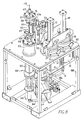
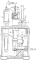
- Figs. 9, 10 and 11 show different isometric views of the apparatus illustrated in Fig. 8 and like reference numerals have been used in these figures.
- the workpiece 420 is secured when the lower tool plate 426 is urged against a spacer 424 which is adjacent to the upper tool plate 422.
- the lower tool plate 426 is moved vertically from an unsecured position to a secured position by hydraulically actuated clamping cylinders 435, 437.
- the clamping cylinders 435, 437 engage the lower tool plate 426, thereby urging it to form a seal against the spacer 424 and the upper tool plate 422 to surround and secure the workpiece 420. While clamping cylinders 435 and 437 are indicated as being hydraulically operated, they may also be electrically operated.
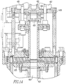
- the associated hardware is also being reduced in size to accommodate the new effective bore CD'.
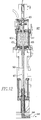
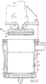
- the same force produced by the actuator 30 on the piston rod 27 may be utilized with a modified piston assembly 24' to generate a higher pressure within the orifice of alternate cylinder 700.
- one characteristic of using high-viscosity media is that a lower volume is used and, therefore, although a higher-force actuator 30 could be utilized, the larger diameter CD of the bore 17 would provide a volume that would not be necessary for a high-viscosity media.
- a heat exchange device such as coils, may be placed around or within one or both of the conditioning cylinders 15, 55, or around the processing cylinder 380. It should be appreciated that a heat exchange device may be placed in any of the piping segments in the apparatus.
- the conditioning and processing cylinders are areas that may be appropriate to position such a heat exchange device.
- a heat exchange device may also be associated with the return cylinder 605.
- the heat exchange device or devices should be capable of closely controlling the temperature of the media and in certain instances the necessary temperature control may be between +/- 0.5 degrees centigrade.
Landscapes
- Engineering & Computer Science (AREA)
- Mechanical Engineering (AREA)
- Finish Polishing, Edge Sharpening, And Grinding By Specific Grinding Devices (AREA)
Abstract
Description
Claims (31)
- A system for abrasive flow machining an orifice in a workpiece wherein the system is capable of using abrasive media having a range of viscosity values, wherein the system is comprised of:a) a processing station having a processing pump and a processing pump actuator to drive the pump, wherein the pump is supplied with media and wherein the pump forces media through the workpiece orifice to machine the orifice and wherein the pump is adapted to accommodate one of eitheri) a primary processing piston and a primary processing cylinder, wherein the primary processing piston has a diameter and wherein the primary processing piston is slidingly positioned within a primary processing cylinder orii) an alternate processing piston and an alternate processing cylinder, wherein the alternate processing piston has a diameter different than the primary processing piston diameter and wherein the alternate processing piston is slidingly positioned within an alternate processing cylinder, andb) wherein the processing pump may utilize the primary processing piston and primary processing cylinder for pumping a low viscosity media through the orifice and may utilize the alternate processing piston and alternate processing cylinder for pumping a higher viscosity media through the orifice.
- The system according to claim 1 wherein the diameter of the primary processing piston is greater than the diameter of the alternate processing piston and the alternate processing cylinder is comprised of a sleeve insertable within the primary processing cylinder and wherein the alternate processing piston is slidably positioned within the sleeve.
- The system according to claim 1 wherein the alternate processing cylinder and the alternate processing piston replace the primary processing cylinder and the primary processing piston.
- The system according to claim 1 further including a conditioning station for conditioning the media prior to introduction to the processing station wherein the conditioning station is comprised ofa) a pump adapted to accommodate one of eitheri) a primary conditioning piston and a primary conditioning cylinder, wherein the primary conditioning piston has a primary diameter and wherein the primary conditioning piston is slidingly positioned within the primary conditioning cylinder orii) an alternate conditioning piston and an alternate conditioning cylinder, wherein the alternate conditioning piston has an alternate conditioning piston with an alternate diameter smaller than the primary diameter and wherein the alternate conditioning piston is slidingly positioned within the alternate conditioning cylinder andb) a mixer which receives media from the pump and mixes the media to impart shear and/or provide homogeneity to the media.
- The system according to claim 4 wherein the alternate conditioning cylinder is comprised of a processing sleeve insertable within the primary conditioning cylinder and the alternate conditioning piston is slidably positioned within the conditioning sleeve.
- The system according to claim 4 wherein the alternate conditioning cylinder and the alternate conditioning piston replace the primary conditioning cylinder and the primary conditioning piston.
- The system according to claim 4 further including a return station between the processing station and the conditioning station for returning the media from the processing station to the conditioning station.
- The system according to claim 7 wherein the return station is comprised of a receptacle to collect media upon discharge from the orifice of the workpiece.
- The system according to claim 7 wherein the conditioning cylinder may be used to create a vacuum to return media to the conditioning cylinder.
- The system according to claim 7 wherein the return station further includes a return pump and a return pump actuator for pumping media to the conditioning station.
- The system according to claim 10 wherein the return pump has a return pump cylinder and return pump piston slidingly therein, wherein the return pump piston provides a seal over the area of the return pump cylinder such that extension of the return pump piston displaces the media in the direction of the extension.
- The system according to claim 10 wherein the return pump has a return pump cylinder and a return pump piston slidingly therein, wherein the return pump piston provides a seal over the area of the return pump cylinder and has a bore extending therethrough such that extension of the return pump piston displaces the media in a direction opposite the direction of the extension.
- The system according to claim 1 further including a second conditioning pump attached in series to the mixer and then to the first conditioning pump such that media may be pumped back and forth through the mixer between conditioning pumps prior to introduction of the media to the processing station.
- The system according to claim 1 wherein the abrasive medium may be selected from medium having a viscosity of between one to one million centipoise.
- The system according to claim 1 further including temperature controllers for controlling the media temperature.
- The system according to claim 15 wherein the temperature controllers are comprised of cooling collars surrounding the conditioning cylinder.
- The system according to claim 15 wherein cooling collars surround the processing cylinder.
- The system according to claim 15 wherein the temperature controllers are selected from among a group of controllers capable of maintaining the temperature of the media within I0.5 degrees centigrade.
- The system according to claim 1 wherein the mixer comprises a container with one or more baffles to impart shear to the media for controlling viscosity in high viscosity media and for stirring the media to impart homogeneity to low viscosity media.
- A method of modifying a device used for abrasive flow machining with an abrasive media having a viscosity for forcing the media through an orifice of a workpiece, wherein the device has a processing station comprised of a processing pump and a processing pump actuator and wherein the processing pump has a primary processing pump cylinder and a primary processing pump piston with a primary diameter slidably positioned within the primary cylinder for forcing the media from the processing station through the orifice, wherein the method is comprised of the step of modifying the diameter of the primary processing pump cylinder and the primary processing piston to accommodate media of different viscosities.
- The method according to claim 20 wherein the step of modifying the diameter of the primary processing piston cylinder and primary processing piston is comprised of inserting a sleeve within the primary processing piston cylinder and slidably positioning an alternate processing piston within the sleeve.
- The method according to claim 20 wherein the step of modifying the diameter of the primary processing piston cylinder and primary processing piston is comprised of replacing the primary processing piston cylinder and the primary processing piston with an alternate processing piston cylinder and an alternate processing piston having a smaller diameter.
- The method according to claim 20 wherein the device is further comprised of a conditioning station for mixing the abrasive media through a mixer and wherein the conditioning station has a conditioning pump with a primary conditioning piston and a primary conditioning cylinder and the method further includes the step of modifying the diameter of the primary conditioning cylinder and primary conditioning piston to accommodate media of different viscosities.
- The method according to claim 23 wherein the step of modifying the diameter of the primary conditioning piston cylinder and the primary conditioning piston is comprised of inserting a sleeve within the primary conditioning piston cylinder and slidably positioning an alternate conditioning piston within the sleeve.
- The method according to claim 23 wherein the step of modifying the diameter of the primary conditioning piston cylinder and the primary conditioning piston is comprised of replacing the primary conditioning piston cylinder and the primary conditioning piston with an alternate conditioning piston cylinder and an alternate conditioning piston having a smaller diameter.
- The method according to claim 23 further including the step of transferring heat to or from the media to maintain a desired temperature.
- The method according to claim 26 further including a return cylinder to collect media upon discharge from the orifice wherein the heat is transferred to or from the media when the media is in the return cylinder.
- The method according to claim 26 where the heat is transferred to or from the media when the media is in the conditioning cylinder.
- A system for abrasive flow machining an orifice of a workpiece, wherein the system hasa) a processing station for introducing media through an orifice in a workpiece;b) a return station, wherein the return station has a double acting piston and the piston is comprised of a return piston slidable within a return piston cylinder, wherein the piston cylinder with the piston in a retracted position accepts media discharged from the processing station and wherein the piston in the extended position forces media from the return station; andc) wherein the piston has a rod attached thereto and each of the piston and the rod have a bore extending therethrough such that when the piston is urged toward the extended position, media is forced through the bore and is directed toward the processing station.
- The system according to claim 29 wherein the piston is hydraulically driven.
- The system according to claim 29 wherein the piston is electrically driven.
Applications Claiming Priority (4)
| Application Number | Priority Date | Filing Date | Title |
|---|---|---|---|
| US23035300P | 2000-09-06 | 2000-09-06 | |
| US230353P | 2000-09-06 | ||
| US931204 | 2001-08-16 | ||
| US09/931,204 US6500050B2 (en) | 2000-09-06 | 2001-08-16 | High precision abrasive flow machining apparatus and method |
Publications (3)
| Publication Number | Publication Date |
|---|---|
| EP1186377A2 true EP1186377A2 (en) | 2002-03-13 |
| EP1186377A3 EP1186377A3 (en) | 2004-01-02 |
| EP1186377B1 EP1186377B1 (en) | 2011-10-19 |
Family
ID=26924150
Family Applications (1)
| Application Number | Title | Priority Date | Filing Date |
|---|---|---|---|
| EP01650099A Expired - Lifetime EP1186377B1 (en) | 2000-09-06 | 2001-09-05 | High precision abrasive flow machining apparatus and method |
Country Status (5)
| Country | Link |
|---|---|
| US (1) | US6500050B2 (en) |
| EP (1) | EP1186377B1 (en) |
| JP (1) | JP4824227B2 (en) |
| CN (1) | CN1137800C (en) |
| AT (1) | ATE529219T1 (en) |
Cited By (3)
| Publication number | Priority date | Publication date | Assignee | Title |
|---|---|---|---|---|
| WO2004004973A1 (en) * | 2002-07-03 | 2004-01-15 | Siemens Aktiengesellschaft | Method for the hydro-erosive rounding of an edge of a part and use thereof |
| DE10323743A1 (en) * | 2003-05-24 | 2004-12-16 | Daimlerchrysler Ag | Freilegemasse, Freilegeverfahren and Freilegevorrichtung |
| EP2594365A1 (en) * | 2011-11-15 | 2013-05-22 | Rolls-Royce Deutschland Ltd & Co KG | Method for determining flow behaviour of a medium |
Families Citing this family (23)
| Publication number | Priority date | Publication date | Assignee | Title |
|---|---|---|---|---|
| JP4887149B2 (en) * | 2003-09-23 | 2012-02-29 | エクストルード ホーン コーポレイション | Method and apparatus for determining whether the orifice geometry of a workpiece is within tolerances of a prototype part |
| US20050186269A1 (en) * | 2004-02-25 | 2005-08-25 | Udell Ronald G. | Stabilized feverfew formulations |
| US7427227B2 (en) * | 2005-08-30 | 2008-09-23 | Denso Corporation | Method and apparatus for fluid polishing |
| US7763453B2 (en) * | 2005-11-30 | 2010-07-27 | Micronics, Inc. | Microfluidic mixing and analytic apparatus |
| JP4569462B2 (en) * | 2005-12-19 | 2010-10-27 | 株式会社デンソー | Fluid polishing method and apparatus |
| US8556681B2 (en) * | 2007-01-29 | 2013-10-15 | Tosoh Smd, Inc. | Ultra smooth face sputter targets and methods of producing same |
| CN100546764C (en) * | 2007-03-21 | 2009-10-07 | 浙江工业大学 | Surface Finishing System Based on Flow Field Constrained Hydrodynamic Abrasive Flow |
| CN102229096B (en) * | 2011-07-05 | 2013-10-16 | 大连隆正光饰机制造有限公司 | Water circulation system of machining center of automatic finishing machine |
| CN103286642B (en) * | 2013-05-14 | 2015-09-23 | 太原理工大学 | A kind of Fluid magnetic abrasive hole finishing processing device |
| US9132528B2 (en) | 2013-10-08 | 2015-09-15 | General Electric Company | Refurbishing system |
| CN103612164B (en) * | 2013-12-03 | 2015-12-30 | 浙江工业大学 | The curved surface turbulent flow burnishing device of current vortex heating confining part |
| US9687953B2 (en) * | 2014-06-27 | 2017-06-27 | Applied Materials, Inc. | Chamber components with polished internal apertures |
| CN104440414B (en) * | 2014-12-07 | 2016-11-09 | 陆颖 | A Constant Pressure Difference Intermittent Rotating Extrusion Abrasive Flow Polishing Device |
| CN104896303B (en) * | 2015-06-11 | 2017-04-12 | 湖南拓奇新创科技股份有限公司 | Automatic polishing auxiliary material discharging device |
| US10759018B2 (en) * | 2015-08-25 | 2020-09-01 | Sundaram-Clayton Limited | Method and apparatus for machining a component |
| CN106041712B (en) * | 2016-06-05 | 2018-06-19 | 广州一通活塞环有限公司 | An automatic feeding device for an automobile piston ring honing machine |
| WO2020046567A1 (en) * | 2018-08-29 | 2020-03-05 | Applied Materials, Inc. | Chamber injector |
| CN113696089A (en) * | 2021-11-01 | 2021-11-26 | 杭州奔涌机械有限公司 | Abrasive polishing equipment |
| CN114734366B (en) * | 2022-06-13 | 2022-09-06 | 中国航发上海商用航空发动机制造有限责任公司 | Finishing device, finishing method and sealing system |
| CN114750078B (en) * | 2022-06-13 | 2022-10-21 | 中国航发上海商用航空发动机制造有限责任公司 | Nozzle, spray stop valve and finishing device |
| CN114734365B (en) * | 2022-06-13 | 2022-09-09 | 中国航发上海商用航空发动机制造有限责任公司 | Surface finishing method of fine inner flow channel, fine inner flow channel workpiece and finishing medium |
| CN114750063B (en) * | 2022-06-13 | 2022-09-13 | 中国航发上海商用航空发动机制造有限责任公司 | Polishing device and polishing method |
| CN116638431A (en) * | 2023-07-10 | 2023-08-25 | 浙江工业大学 | A low-temperature refrigeration cycle device for abrasive flow polishing and its working method |
Family Cites Families (18)
| Publication number | Priority date | Publication date | Assignee | Title |
|---|---|---|---|---|
| SU51826A1 (en) | 1934-03-14 | 1936-11-30 | Г.Х. Христиансен | Motor vehicle wagon attachment |
| US3039234A (en) * | 1959-05-21 | 1962-06-19 | Gen Dynamics Corp | Honing apparatus |
| US3521412A (en) | 1968-04-12 | 1970-07-21 | Extrude Hone Inc | Method of honing by extruding |
| US3630642A (en) * | 1970-02-03 | 1971-12-28 | Du Pont | Diaphragm pump |
| US3728821A (en) * | 1971-09-13 | 1973-04-24 | Dynetics Corp | Machine for finishing surfaces |
| US4005549A (en) * | 1975-07-28 | 1977-02-01 | Dynetics Corporation | Abrasive flow machining method and tooling |
| US5125191A (en) | 1982-09-08 | 1992-06-30 | Extrude Hone Corporation | Abrasive flow machining with an in situ viscous plastic medium |
| WO1987005552A1 (en) * | 1986-03-21 | 1987-09-24 | Rhoades Lawrence J | Method of controlling flow resistance in fluid orifice manufacture |
| US5054247A (en) | 1986-03-21 | 1991-10-08 | Extrude Hone Corporation | Method of controlling flow resistance in fluid orifice manufacture |
| US5137368A (en) * | 1989-06-21 | 1992-08-11 | Specified Equipment Systems Co., Inc. | Viscous fluid pumping apparatus and system |
| US5070652A (en) | 1990-10-31 | 1991-12-10 | Extrude Hone Corporation | Reversible unidirectional abrasive flow machining |
| JP3265628B2 (en) * | 1992-07-20 | 2002-03-11 | トヨタ自動車株式会社 | Processing apparatus and processing method using abrasive fluid |
| US5367833A (en) | 1993-10-22 | 1994-11-29 | Extrude Hone Corporation | Unidirectional abrasive flow machining |
| JPH07266216A (en) * | 1994-03-31 | 1995-10-17 | Hitachi Ltd | Abrasive fluid processing equipment |
| US5494102A (en) * | 1995-03-27 | 1996-02-27 | Schulte; Warren H. | Downhole hydraulically operated fluid pump |
| DE844920T1 (en) | 1995-08-04 | 2001-04-05 | Dynetics Corp., Woburn | METHOD AND DEVICE FOR FORMING AN OPENING BY MEANS OF A PICTURE |
| US6132482A (en) | 1996-11-12 | 2000-10-17 | Dynetics Corporation | Abrasive liquid slurry for polishing and radiusing a microhole |
| US6273787B1 (en) * | 1998-08-26 | 2001-08-14 | Extrude Hone Corp | Abrasive polishing method, apparatus and composition |
-
2001
- 2001-08-16 US US09/931,204 patent/US6500050B2/en not_active Expired - Lifetime
- 2001-09-05 AT AT01650099T patent/ATE529219T1/en not_active IP Right Cessation
- 2001-09-05 EP EP01650099A patent/EP1186377B1/en not_active Expired - Lifetime
- 2001-09-06 JP JP2001269790A patent/JP4824227B2/en not_active Expired - Lifetime
- 2001-09-06 CN CNB011326700A patent/CN1137800C/en not_active Expired - Lifetime
Cited By (6)
| Publication number | Priority date | Publication date | Assignee | Title |
|---|---|---|---|---|
| WO2004004973A1 (en) * | 2002-07-03 | 2004-01-15 | Siemens Aktiengesellschaft | Method for the hydro-erosive rounding of an edge of a part and use thereof |
| US7052361B2 (en) | 2002-07-03 | 2006-05-30 | Siemens Aktiengesellschaft | Method for hydro-erosive rounding of an edge of a part and use thereof |
| DE10323743A1 (en) * | 2003-05-24 | 2004-12-16 | Daimlerchrysler Ag | Freilegemasse, Freilegeverfahren and Freilegevorrichtung |
| DE10323743B4 (en) * | 2003-05-24 | 2007-01-18 | Daimlerchrysler Ag | Freilegemasse, Freilegeverfahren and Freilegevorrichtung |
| EP2594365A1 (en) * | 2011-11-15 | 2013-05-22 | Rolls-Royce Deutschland Ltd & Co KG | Method for determining flow behaviour of a medium |
| US9330231B2 (en) | 2011-11-15 | 2016-05-03 | Rolls-Royce Deutschland Ltd & Co Kg | Method for determining a flow behavior of a medium |
Also Published As
| Publication number | Publication date |
|---|---|
| ATE529219T1 (en) | 2011-11-15 |
| CN1347788A (en) | 2002-05-08 |
| JP4824227B2 (en) | 2011-11-30 |
| JP2002126994A (en) | 2002-05-08 |
| US6500050B2 (en) | 2002-12-31 |
| EP1186377B1 (en) | 2011-10-19 |
| CN1137800C (en) | 2004-02-11 |
| EP1186377A3 (en) | 2004-01-02 |
| US20020028633A1 (en) | 2002-03-07 |
Similar Documents
| Publication | Publication Date | Title |
|---|---|---|
| EP1186377B1 (en) | High precision abrasive flow machining apparatus and method | |
| KR100571126B1 (en) | Floating abrasive grinding machine and floating abrasive grinding method | |
| DE69427483T2 (en) | PROCESSING BY A SINGLE-SIDED ABRASIVE CURRENT | |
| EP2996840B1 (en) | Arrangements and methods for abrasive flow machining | |
| US4312463A (en) | Proportional pumping apparatus | |
| Fletcher et al. | Computer modelling of the abrasive flow machining process | |
| EP2357034A1 (en) | Liquid mixing device | |
| US20210154799A1 (en) | Abrasive suspension jet cutting system having reduced system wear and process materials reclamation | |
| DE102004046316A1 (en) | Method and apparatus for compressing a gaseous medium | |
| DE112007002079T5 (en) | Fluid jet polishing with a constant pressure pump | |
| EP2308646B1 (en) | Method for working on workpieces by means of a water jet that contains abrasive and emerges under high pressure from a nozzle, water jet installation for executing the method, and application of the method | |
| US3039234A (en) | Honing apparatus | |
| EP0786595A2 (en) | Method and apparatus for pressure processing a pumpable substance | |
| EP3636936A1 (en) | Hydraulic pressure intensifier and method for producing an axial compression stress in the high pressure cylinder | |
| JP3265628B2 (en) | Processing apparatus and processing method using abrasive fluid | |
| DE19915265A1 (en) | Minimal quantity cooling-lubrication for machining processes involves atomising lubricant independently of and separately from delivery of compressed air, e.g. with injection pump | |
| US20240110734A1 (en) | Compressor, in particular refrigerant compressor, refrigeration machine, and method for producing a compressor | |
| JP3737467B2 (en) | Fine hole processing equipment | |
| JP2002248328A (en) | Emulsifying and dispersing equipment | |
| DE2317357A1 (en) | HIGH PRESSURE PUMP WITH SEAL | |
| DD227372A1 (en) | METHOD FOR FINISHING STEEL TUBES | |
| JP2003200084A (en) | Paint supply method and paint supply device | |
| EP0515914B1 (en) | Homogenising machine and its method of operation | |
| EP3073112A1 (en) | Device and method for metering liquids | |
| DE102018126444A1 (en) | Device for homogenizing a product and use of the device for homogenizing a product |
Legal Events
| Date | Code | Title | Description |
|---|---|---|---|
| PUAI | Public reference made under article 153(3) epc to a published international application that has entered the european phase |
Free format text: ORIGINAL CODE: 0009012 |
|
| AK | Designated contracting states |
Kind code of ref document: A2 Designated state(s): AT BE CH CY DE DK ES FI FR GB GR IE IT LI LU MC NL PT SE TR |
|
| AX | Request for extension of the european patent |
Free format text: AL;LT;LV;MK;RO;SI |
|
| PUAL | Search report despatched |
Free format text: ORIGINAL CODE: 0009013 |
|
| AK | Designated contracting states |
Kind code of ref document: A3 Designated state(s): AT BE CH CY DE DK ES FI FR GB GR IE IT LI LU MC NL PT SE TR |
|
| AX | Request for extension of the european patent |
Extension state: AL LT LV MK RO SI |
|
| 17P | Request for examination filed |
Effective date: 20040702 |
|
| AKX | Designation fees paid |
Designated state(s): AT BE CH CY DE DK ES FI FR GB GR IE IT LI LU MC NL PT SE TR |
|
| 17Q | First examination report despatched |
Effective date: 20041109 |
|
| GRAP | Despatch of communication of intention to grant a patent |
Free format text: ORIGINAL CODE: EPIDOSNIGR1 |
|
| GRAS | Grant fee paid |
Free format text: ORIGINAL CODE: EPIDOSNIGR3 |
|
| GRAA | (expected) grant |
Free format text: ORIGINAL CODE: 0009210 |
|
| AK | Designated contracting states |
Kind code of ref document: B1 Designated state(s): AT BE CH CY DE DK ES FI FR GB GR IE IT LI LU MC NL PT SE TR |
|
| REG | Reference to a national code |
Ref country code: GB Ref legal event code: FG4D |
|
| REG | Reference to a national code |
Ref country code: CH Ref legal event code: EP |
|
| REG | Reference to a national code |
Ref country code: IE Ref legal event code: FG4D |
|
| REG | Reference to a national code |
Ref country code: DE Ref legal event code: R096 Ref document number: 60145535 Country of ref document: DE Effective date: 20111208 |
|
| REG | Reference to a national code |
Ref country code: NL Ref legal event code: VDEP Effective date: 20111019 |
|
| REG | Reference to a national code |
Ref country code: AT Ref legal event code: MK05 Ref document number: 529219 Country of ref document: AT Kind code of ref document: T Effective date: 20111019 |
|
| PG25 | Lapsed in a contracting state [announced via postgrant information from national office to epo] |
Ref country code: BE Free format text: LAPSE BECAUSE OF FAILURE TO SUBMIT A TRANSLATION OF THE DESCRIPTION OR TO PAY THE FEE WITHIN THE PRESCRIBED TIME-LIMIT Effective date: 20111019 |
|
| PG25 | Lapsed in a contracting state [announced via postgrant information from national office to epo] |
Ref country code: NL Free format text: LAPSE BECAUSE OF FAILURE TO SUBMIT A TRANSLATION OF THE DESCRIPTION OR TO PAY THE FEE WITHIN THE PRESCRIBED TIME-LIMIT Effective date: 20111019 Ref country code: PT Free format text: LAPSE BECAUSE OF FAILURE TO SUBMIT A TRANSLATION OF THE DESCRIPTION OR TO PAY THE FEE WITHIN THE PRESCRIBED TIME-LIMIT Effective date: 20120220 Ref country code: SE Free format text: LAPSE BECAUSE OF FAILURE TO SUBMIT A TRANSLATION OF THE DESCRIPTION OR TO PAY THE FEE WITHIN THE PRESCRIBED TIME-LIMIT Effective date: 20111019 Ref country code: GR Free format text: LAPSE BECAUSE OF FAILURE TO SUBMIT A TRANSLATION OF THE DESCRIPTION OR TO PAY THE FEE WITHIN THE PRESCRIBED TIME-LIMIT Effective date: 20120120 |
|
| PG25 | Lapsed in a contracting state [announced via postgrant information from national office to epo] |
Ref country code: CY Free format text: LAPSE BECAUSE OF FAILURE TO SUBMIT A TRANSLATION OF THE DESCRIPTION OR TO PAY THE FEE WITHIN THE PRESCRIBED TIME-LIMIT Effective date: 20111019 |
|
| PG25 | Lapsed in a contracting state [announced via postgrant information from national office to epo] |
Ref country code: DK Free format text: LAPSE BECAUSE OF FAILURE TO SUBMIT A TRANSLATION OF THE DESCRIPTION OR TO PAY THE FEE WITHIN THE PRESCRIBED TIME-LIMIT Effective date: 20111019 |
|
| PLBE | No opposition filed within time limit |
Free format text: ORIGINAL CODE: 0009261 |
|
| STAA | Information on the status of an ep patent application or granted ep patent |
Free format text: STATUS: NO OPPOSITION FILED WITHIN TIME LIMIT |
|
| 26N | No opposition filed |
Effective date: 20120720 |
|
| REG | Reference to a national code |
Ref country code: DE Ref legal event code: R097 Ref document number: 60145535 Country of ref document: DE Effective date: 20120720 |
|
| PG25 | Lapsed in a contracting state [announced via postgrant information from national office to epo] |
Ref country code: AT Free format text: LAPSE BECAUSE OF FAILURE TO SUBMIT A TRANSLATION OF THE DESCRIPTION OR TO PAY THE FEE WITHIN THE PRESCRIBED TIME-LIMIT Effective date: 20111019 |
|
| PG25 | Lapsed in a contracting state [announced via postgrant information from national office to epo] |
Ref country code: ES Free format text: LAPSE BECAUSE OF FAILURE TO SUBMIT A TRANSLATION OF THE DESCRIPTION OR TO PAY THE FEE WITHIN THE PRESCRIBED TIME-LIMIT Effective date: 20120130 Ref country code: MC Free format text: LAPSE BECAUSE OF NON-PAYMENT OF DUE FEES Effective date: 20120930 |
|
| REG | Reference to a national code |
Ref country code: CH Ref legal event code: PL |
|
| REG | Reference to a national code |
Ref country code: IE Ref legal event code: MM4A |
|
| PG25 | Lapsed in a contracting state [announced via postgrant information from national office to epo] |
Ref country code: FI Free format text: LAPSE BECAUSE OF FAILURE TO SUBMIT A TRANSLATION OF THE DESCRIPTION OR TO PAY THE FEE WITHIN THE PRESCRIBED TIME-LIMIT Effective date: 20111019 |
|
| PG25 | Lapsed in a contracting state [announced via postgrant information from national office to epo] |
Ref country code: CH Free format text: LAPSE BECAUSE OF NON-PAYMENT OF DUE FEES Effective date: 20120930 Ref country code: IE Free format text: LAPSE BECAUSE OF NON-PAYMENT OF DUE FEES Effective date: 20120905 Ref country code: LI Free format text: LAPSE BECAUSE OF NON-PAYMENT OF DUE FEES Effective date: 20120930 |
|
| PG25 | Lapsed in a contracting state [announced via postgrant information from national office to epo] |
Ref country code: TR Free format text: LAPSE BECAUSE OF FAILURE TO SUBMIT A TRANSLATION OF THE DESCRIPTION OR TO PAY THE FEE WITHIN THE PRESCRIBED TIME-LIMIT Effective date: 20111019 |
|
| PG25 | Lapsed in a contracting state [announced via postgrant information from national office to epo] |
Ref country code: LU Free format text: LAPSE BECAUSE OF NON-PAYMENT OF DUE FEES Effective date: 20120905 |
|
| REG | Reference to a national code |
Ref country code: DE Ref legal event code: R082 Ref document number: 60145535 Country of ref document: DE Representative=s name: PRINZ & PARTNER MBB PATENTANWAELTE RECHTSANWAE, DE |
|
| PGFP | Annual fee paid to national office [announced via postgrant information from national office to epo] |
Ref country code: GB Payment date: 20140903 Year of fee payment: 14 |
|
| PGFP | Annual fee paid to national office [announced via postgrant information from national office to epo] |
Ref country code: IT Payment date: 20140912 Year of fee payment: 14 |
|
| REG | Reference to a national code |
Ref country code: DE Ref legal event code: R081 Ref document number: 60145535 Country of ref document: DE Owner name: KENNAMETAL EXTRUDE HONE CORP., IRWIN, US Free format text: FORMER OWNER: EXTRUDE HONE CORP., IRWIN, PA., US Effective date: 20111020 Ref country code: DE Ref legal event code: R081 Ref document number: 60145535 Country of ref document: DE Owner name: KENNAMETAL EXTRUDE HONE CORP., IRWIN, US Free format text: FORMER OWNER: EXTRUDE HONE CORP., IRWIN, PA., US Effective date: 20141120 Ref country code: DE Ref legal event code: R082 Ref document number: 60145535 Country of ref document: DE Representative=s name: PRINZ & PARTNER MBB PATENTANWAELTE RECHTSANWAE, DE Effective date: 20141120 |
|
| REG | Reference to a national code |
Ref country code: FR Ref legal event code: PLFP Year of fee payment: 15 |
|
| PG25 | Lapsed in a contracting state [announced via postgrant information from national office to epo] |
Ref country code: IT Free format text: LAPSE BECAUSE OF NON-PAYMENT OF DUE FEES Effective date: 20150905 |
|
| GBPC | Gb: european patent ceased through non-payment of renewal fee |
Effective date: 20150905 |
|
| PG25 | Lapsed in a contracting state [announced via postgrant information from national office to epo] |
Ref country code: GB Free format text: LAPSE BECAUSE OF NON-PAYMENT OF DUE FEES Effective date: 20150905 |
|
| REG | Reference to a national code |
Ref country code: FR Ref legal event code: PLFP Year of fee payment: 16 |
|
| REG | Reference to a national code |
Ref country code: FR Ref legal event code: PLFP Year of fee payment: 17 |
|
| PGFP | Annual fee paid to national office [announced via postgrant information from national office to epo] |
Ref country code: FR Payment date: 20170928 Year of fee payment: 17 |
|
| PG25 | Lapsed in a contracting state [announced via postgrant information from national office to epo] |
Ref country code: FR Free format text: LAPSE BECAUSE OF NON-PAYMENT OF DUE FEES Effective date: 20180930 |
|
| PGFP | Annual fee paid to national office [announced via postgrant information from national office to epo] |
Ref country code: DE Payment date: 20190926 Year of fee payment: 19 |
|
| REG | Reference to a national code |
Ref country code: DE Ref legal event code: R119 Ref document number: 60145535 Country of ref document: DE |
|
| PG25 | Lapsed in a contracting state [announced via postgrant information from national office to epo] |
Ref country code: DE Free format text: LAPSE BECAUSE OF NON-PAYMENT OF DUE FEES Effective date: 20210401 |