EP1186223A1 - Support structure for a divider of an agricultural corn head. - Google Patents
Support structure for a divider of an agricultural corn head. Download PDFInfo
- Publication number
- EP1186223A1 EP1186223A1 EP01203368A EP01203368A EP1186223A1 EP 1186223 A1 EP1186223 A1 EP 1186223A1 EP 01203368 A EP01203368 A EP 01203368A EP 01203368 A EP01203368 A EP 01203368A EP 1186223 A1 EP1186223 A1 EP 1186223A1
- Authority
- EP
- European Patent Office
- Prior art keywords
- divider
- header according
- support
- pivotal attachment
- tension
- Prior art date
- Legal status (The legal status is an assumption and is not a legal conclusion. Google has not performed a legal analysis and makes no representation as to the accuracy of the status listed.)
- Granted
Links
- 240000008042 Zea mays Species 0.000 title abstract description 52
- 235000005824 Zea mays ssp. parviglumis Nutrition 0.000 title abstract description 52
- 235000002017 Zea mays subsp mays Nutrition 0.000 title abstract description 52
- 235000005822 corn Nutrition 0.000 title abstract description 52
- 230000007246 mechanism Effects 0.000 claims description 16
- 230000014759 maintenance of location Effects 0.000 claims description 10
- 238000003306 harvesting Methods 0.000 claims description 9
- 210000005069 ears Anatomy 0.000 description 17
- 239000000463 material Substances 0.000 description 12
- 241001057636 Dracaena deremensis Species 0.000 description 5
- 238000000034 method Methods 0.000 description 3
- 244000038559 crop plants Species 0.000 description 2
- 239000010903 husk Substances 0.000 description 2
- 239000002184 metal Substances 0.000 description 2
- 230000008569 process Effects 0.000 description 2
- 238000003860 storage Methods 0.000 description 2
- 241000196324 Embryophyta Species 0.000 description 1
- 230000000712 assembly Effects 0.000 description 1
- 238000000429 assembly Methods 0.000 description 1
- 238000004140 cleaning Methods 0.000 description 1
- 238000010276 construction Methods 0.000 description 1
- 230000005484 gravity Effects 0.000 description 1
- 238000012986 modification Methods 0.000 description 1
- 230000004048 modification Effects 0.000 description 1
- 238000011084 recovery Methods 0.000 description 1
- 230000008439 repair process Effects 0.000 description 1
- 238000000926 separation method Methods 0.000 description 1
- 238000004904 shortening Methods 0.000 description 1
Images


Classifications
-
- A—HUMAN NECESSITIES
- A01—AGRICULTURE; FORESTRY; ANIMAL HUSBANDRY; HUNTING; TRAPPING; FISHING
- A01D—HARVESTING; MOWING
- A01D45/00—Harvesting of standing crops
- A01D45/02—Harvesting of standing crops of maize, i.e. kernel harvesting
- A01D45/021—Cornheaders
Definitions
- the present invention relates generally to a header for an agricultural harvesting machine, such as a combine. It relates particularly to support means for the dividers on such header.
- An agricultural combine is a common and well-known machine for harvesting crop materials.
- Agricultural combines are available in various designs and models to perform the basic functions of reaping crop materials from a crop field, separating the grain from the non-grain crop materials, and discarding the non-grain crop materials back onto the crop field.
- a typical combine includes a crop harvesting apparatus, or header, which reaps ripened crop plants from the crop field.
- the header then feeds the crop materials rearwardly to a threshing system which separates the grain and fine non-grain materials from the coarse non-grain materials.
- the grain and fine non-grain materials are then directed to a series of moving sieves which further separate the grain from the fine non-grain materials with the aid of a cleaning fan.
- the grain is conveyed up to an onboard storage bin, while the coarse and fine non-grain materials are discharged from the rear end of the combine onto the harvested crop field.
- a corn header is a specially designed header that is used for stripping ripened corn ears from the plant stalks. The corn header then feeds the corn ears rearwardly to the combine, where the corn is separated from the cob and the husks.
- corn is planted in crop fields in a number of parallel rows which can range from 38 cm to 102 cm in width.
- the corn head therefore, includes a number of individual row units that are spaced apart along the width of the corn header so that each row unit operates on a separate row of corn.
- Corn heads are available in a number of different widths, commonly ranging between four rows and twelve rows in width.
- the row units perform the critical task of stripping the corn ears from the stalks.
- a narrow opening is provided that extends between two stripper plates approximately two to three feet in the direction of the corn rows.
- the narrow opening is wide enough to allow the corn stalks to travel freely through the length of the opening but is narrower than the diameter of the corn ears.
- a set of stalk rolls which are installed under the narrow opening, with one stalk roll positioned on each side of the opening.
- Each of the stalk rolls includes a cylindrical body with spiral vanes that extend outward from the cylinder's surface. The stalk rolls then rotate around an approximately horizontal axis which is in a plane parallel to the corn rows and the narrow opening.
- this funnelling system that directs the corn plants to the narrow opening when the row unit and corn row are misaligned.
- this funnelling system includes a divider that is made from sheet metal or plastic and which forms an elongated shield between adjacent row units. The divider, therefore, extends forward from the row units and travels between the rows of corn.
- the divider further includes a pointed forward end and an expanded rear end that spans between adjacent narrow openings.
- an adjustment mechanism is provided for adjusting the height of the divider to allow the divider to effectively funnel corn plants of various heights and conditions.
- the corn is broken down by wind prior to harvest so that the crop stalks are lying near the ground.
- the dividers can be adjusted downwards to allow recovery of the fallen crops.
- the divider is lowered all the way down near the ground surface so that the bottom of the divider skims the ground.
- the dividers can be raised several feet off the ground to minimise the portion of the corn stalks that must be fed through the stripper plates.
- One known mechanism includes a tension shaft assembly that extends from the front end of the divider to a rearward support structure.
- This mechanism uses a series locking holes and a lock pin to vary the length of the shaft assembly, which correspondingly adjusts the height of the divider.
- This mechanism has the disadvantage, however, of providing only a limited number of height adjustments based on the number of holes provided and their spacing.
- a tension chain assembly with an L screw.
- the chain includes a number of links and extends between the front end of the divider and a rearward support.
- the L screw is attached between one end of the chain and the front or rear connecting point.
- the length of the assembly, and consequently the height of the divider is then adjusted in a two step process. Accordingly, the height is first roughly set by removing or adding links of the chain to the tension length. Next, the height can be fine tuned by adjusting the L screw inward or outwards. This adjusting process is time consuming, however, and can require repeated trials to arrive at the desired height.
- Another disadvantage of this mechanism is the existence of a loose flopping member that can become entangled with the fingers of the gathering chain.
- dividers Another problem with dividers is the long length of the divider that extends past the front end of the row units. Typically, the dividers extend approximately three to four feet in front of the row units in order to effectively funnel the crop rows.
- This extended length is a disadvantage when the combine is being transported from location to location or when the corn header is being shipped from the manufacturer. During farm transportation this extended length creates a collision hazard, which the combine operator must be attentive to.
- the manufacturer's shipping costs are increased because of the extended dividers. Typically, shipping costs are calculated based on the volume of the product being shipped. Manufacturers, therefore, regularly try to reduce these costs by minimising unnecessary extending portions which require additional shipping volume.
- a header for an agricultural harvesting machine comprising:
- Such tension assembly of a divider can buckle upwards along a predetermined and predictable travel path when the divider strikes ground objects.
- the buckling system may comprise a support member for the divider which is pivotally connected to the row unit and to a second member of the tension assembly. Alignment of the tension lines of the first and second members may be prevented by a stop. Thus is provided a fixed rest position for the divider from where it may be lifted upwardly.
- the tension lines may be at a small angle e.g. 10°.
- a clearance opening through a lateral hood support adjacent the tension assembly may be provided. This allows additional travel of the members of the tension assembly. It is also possible to gain travel clearance by providing one of the members with a bended shape.
- the buckling system may also comprise a height adjustment mechanism with infinite adjustments within a range.
- Such mechanism may be constituted by a turnbuckle and comprise a locking member for tightening against the turnbuckle without using a wrench.
- the support member may sustain the divider in both an operating and a transport or service position.
- the header may comprise a crop shield pivotally connected to the divider allowing the raising up of said connection to said transport or service position.
- the divider may be kept in place by locking members on the support means and divider.
- One locking member may be a retention pin on the support and the other locking member may be a retention hole in the divider.
- the support member may be adapted for assuming a shipping position that minimises the portion that extends beyond the front end of the row units. To this end the pivot of the first member may be detached from the row unit and rotated, together with the support member to a retracted position below the row units.
- the combine 10 includes a body 12 supported by wheels 14 and an engine (not shown) for driving the wheels 14 to allow the combine 10 to move from place to place.
- An operator's station 16 is positioned towards the forward end of the combine body 12 and includes numerous controls to allow the operator to adjust the functions of the combine 10.
- Corn heads 18 are well-known to those skilled in the art of agricultural combines 10 and only a brief explanation of its operation will be necessary.
- the corn header 18 includes a number of row units 24 that are usually equally spaced along the width of the header 18. Each row unit 24 thus operates on a single row of corn as the combine 10 travels through the crop field.
- the row units 24 include a set of stripper plates 26 that are installed on each side of a narrow opening 28.
- the narrow opening 28 extends forward and has a front entrance opening which allows crop stalks to enter the narrow opening 28 as the combine 10 travels through the field.
- a corresponding set of stalk rolls 30 is installed under the stripper plates 26.
- Each of the stalk rolls 30 includes a cylindrical body (not shown) and a number of spiral vanes (not shown) attached to the exterior of the cylindrical body. The cylindrical body is then rotatably connected to the row unit 24 so that the axis of rotation is generally horizontal and parallel to the narrow opening 28.
- the spiral vanes of the stalk rolls 30 engage the stalk on each side of the row.
- the stalk rolls 30 are rotatably driven so that the stalks are pulled downward by the stalk rolls 30 through the narrow opening 28.
- the width of the narrow opening 28 is specially sized to allow the stalks to freely travel through the opening 28 but to prevent the corn ears from travelling through the opening 28.
- a set of gathering chains 34 then feed the stripped ears rearward.
- the gathering chains 34 include a number of extended fingers 35 that engage and push the loose ears rearward.
- Each gathering chain 34 is installed above one of the stripper plates 26.
- the gathering conveyor is a large cylindrical rotating member that extends across the width of the corn header 18 and includes spiral vanes for engaging the corn ears.
- the gathering conveyor then feeds the ears to a feeder housing 20 which feeds the ears rearward into the combine body 12 where the grain is separated from the cobs and the husks. After separation, the grain is stored in an onboard storage bin 22 and the non-grain materials are discharged from the rear end of the combine.
- a divider 38 is provided which travels between the rows of corn and funnels the rows of corn into the narrow opening 28 as the combine 10 travels through the field.
- the divider 38 is a sheet metal or plastic shield that extends forward from the row units 24 and has a narrow pointed front end 39 and a wider rear end 40 that extends between adjacent narrow openings 28.
- the divider 38 is pivotally attached 37 to a hood 36.
- the hood 36 is a shield that extends from the rear end 40 of the divider 38 and along the top side of the row units 24. The hood 36, thus, protects the top side of the row units 24 from crop debris and directs the stripped corn ears down to the gathering chain fingers 35.
- a support structure 50 is provided under the divider 38 for providing vertical and lateral support to the divider 38. Accordingly, the divider 38 rests upon the support structure 50 through an interior support cage 42.
- the support structure 50 is attached to the row units 24 with a pivot support member 52 that extends between two adjacent row units 24. Pivotally attached 53 to the pivot support member 52 are two longitudinal support members 54 that extend forward beyond the row units 24. At the forward end of the longitudinal support members 54 is a cross support member 56 that is fixedly connected to the longitudinal support members 54.
- the longitudinal support members 54 and the cross support member 56 are formed from a single U-shaped member.
- a tension assembly 60 is pivotally attached at A along its rear end to the pivot support member and is pivotally attached at B along its front end to the cross support 56.
- the tension assembly 60 is a multiple piece assembly that includes a first member 62 and a second member 64.
- the rear end of the first member 62 is pivotally attached at A to the pivot support member 52, and the front end of the second member 64 is pivotally attached at B to the cross support 56.
- the front end of the first member 62 and the rear end of the second member 64 are then pivotally attached to each other through a pivot pin 66.
- a stop pin 68 is installed through the clevis 65 of the first member 62 and rests against the top side of the second member 64 when the support structure 50 is in its bottom, at rest position.
- the tension assembly 60 performs several different functions.
- the tension assembly 60 resists gravity to support the longitudinal support members 54 in their bottom, at rest position.
- the tension assembly 60 also provides a height adjustment mechanism 70 for raising or lowering the position of the divider 38.
- the height adjustment mechanism 70 is a turnbuckle 70.
- Turnbuckles 70 are well-known in the art and include oppositely threaded rods 71 that are screwed into opposing ends of the turnbuckle frame 72.
- the second tension member 64 is shortened and is lengthened when the turnbuckle frame 72 is turned in the other direction.
- the longitudinal support members 54 and the divider 38 raise and lower as the turnbuckle frame 72 is turned.
- a locking member 74 is threaded onto one of the rods 71 and can be tightened against the turnbuckle frame 72 in order to resist unwanted vibrational turning of the frame 72.
- the locking member 74 may take the form of a lock nut or may be a specially shaped plate 74 that can be tightened without a wrench.
- the tension assembly 60 buckles upward when an object from the ground is struck by the support structure 50. Often combine operators will lower the corn header 18 and adjust the dividers 38 downward with the turnbuckle 70 so that the support structure 50 travels near the ground surface. It is expected in this situation that raised objects from the ground will be frequently struck by the bottom side of the support structure 50.
- the construction of the tension assembly 60 allows the support structure 50 to raise up over the underlying objects. To achieve this end the stop pin 68 is positioned to prevent the lines of tension 50 of the first and second members 62, 64 from aligning with each other.
- an angle E of about 10° is formed between the line of tension C of the first member 62, which extends between its rear pivot connection A and the pivot pin 66, and the line of tension D of the second member 64, which extends between its front pivot connection B and the pivot pin 66.
- This angle E then allows the first and second members 62, 64 to rotate upwards through the pivot pin 66 and correspondingly raise the longitudinal support members 54 when an underlying object is struck.
- the rigid first and second tension members 62, 64 also eliminate entanglement problems that occur with chain support systems.
- the divider 38 is also capable of buckling upwards when an underlying object is struck.
- the chain in these systems becomes loose during buckling and consequently can flop around and become entangled in nearby assemblies.
- the tension members 62, 64 of this embodiment of the invention travel along predetermined and predictable paths during buckling, thus removing the risk of entanglement.
- the apparatus also provides a clearance opening 76 in the lateral hood support 78 to allow for free movement of the first tension member 62.
- the lateral hood support 78 typically extends between the width of the hood 36 to laterally support the width of hood 36. Attaching mechanisms 79 may also be provided to fixedly attach the hood support 78, and consequently the hood 36 and the divider 38, to the row units 24 during harvesting.
- the rear connecting point A of the first tension member 62 is located behind the lateral hood support 78. Therefore, a clearance opening 76 of sufficient height is provided through the lateral hood support 78 to accommodate the expected upward movement of the first tension member 62.
- the first tension member 62 has been shaped with a downward bend away from the line of tension C to also provide clearance.
- 60 mm of clearance is provided between the lateral hood support 78 and the first tension member 62.
- the height of the clearance opening 76 is about 80 mm.
- the top surface 63 of the first tension member 62 is also bent downward about 12 mm from the line of tension C.
- a retention pin 80 is provided at the front end of the support structure 50 for shortening the extended length of the divider 38 and raising the hood 36 and the divider 38 from the row units 24. This feature is provided to minimise the collision hazard presented by the long, forward extending dividers 38 during transport.
- a secure service position of the hood 36 and the divider 38 is provided. Therefore, a receiver 82 is also provided at the forward end 39 of the divider 38.
- a retention hole 84 is provided through the receiver 82 for receiving the retention pin 80.
- the front end 39 of the divider 38 can be relocated rearward and locked into place with the retention pin 80 and hole 84.
- the front end 39 of the divider 38 then rests between extended arms 55 that support the retention pin 80.
- the extended length of the divider 38 therefore is substantially reduced.
- the row unit 24 can be easily accessed and serviced when the hood 36 and divider 38 are raised in this position.
- the retention pin 80 thus securely retains the hood 36 and the divider 38 in this raised position to prevent them from falling while a person is working underneath.
- the support structure 50 can also be repositioned to provide a compact package during shipping of the corn header 18.
- the divider 38 is disconnected from the support structure 50 and shipped unattached.
- the rear connecting point A of the first tension member 62 is then disconnected to allow the longitudinal support members 54 to freely rotate around their pivot connections 53. This allows the support structure 50 to be rotated around so that the support structure 50 is facing rearward instead of forward. Thus in this rearward shipping position, the support structure 50 no longer extends beyond the forward end of the row units 24.
- the tension assembly 60 can then be secured in place by either strapping the assembly 60 down with appropriate shipping materials, or preferably, the rear end of the first tension member 62 is reconnected to its connecting point A.
Landscapes
- Life Sciences & Earth Sciences (AREA)
- Environmental Sciences (AREA)
- Outside Dividers And Delivering Mechanisms For Harvesters (AREA)
- Harvesting Machines For Specific Crops (AREA)
- Packages (AREA)
Abstract
Description
- The present invention relates generally to a header for an agricultural harvesting machine, such as a combine. It relates particularly to support means for the dividers on such header.
- An agricultural combine is a common and well-known machine for harvesting crop materials. Agricultural combines are available in various designs and models to perform the basic functions of reaping crop materials from a crop field, separating the grain from the non-grain crop materials, and discarding the non-grain crop materials back onto the crop field.
- A typical combine includes a crop harvesting apparatus, or header, which reaps ripened crop plants from the crop field. The header then feeds the crop materials rearwardly to a threshing system which separates the grain and fine non-grain materials from the coarse non-grain materials. The grain and fine non-grain materials are then directed to a series of moving sieves which further separate the grain from the fine non-grain materials with the aid of a cleaning fan. Finally, the grain is conveyed up to an onboard storage bin, while the coarse and fine non-grain materials are discharged from the rear end of the combine onto the harvested crop field.
- One type of header that is used for reaping and gathering crop plants, which is well-known to those skilled in the art of combines, is a corn head. A corn header is a specially designed header that is used for stripping ripened corn ears from the plant stalks. The corn header then feeds the corn ears rearwardly to the combine, where the corn is separated from the cob and the husks. Typically, corn is planted in crop fields in a number of parallel rows which can range from 38 cm to 102 cm in width. The corn head, therefore, includes a number of individual row units that are spaced apart along the width of the corn header so that each row unit operates on a separate row of corn. Corn heads are available in a number of different widths, commonly ranging between four rows and twelve rows in width.
- The row units perform the critical task of stripping the corn ears from the stalks. To accomplish this task, a narrow opening is provided that extends between two stripper plates approximately two to three feet in the direction of the corn rows. The narrow opening is wide enough to allow the corn stalks to travel freely through the length of the opening but is narrower than the diameter of the corn ears. Also provided is a set of stalk rolls which are installed under the narrow opening, with one stalk roll positioned on each side of the opening. Each of the stalk rolls includes a cylindrical body with spiral vanes that extend outward from the cylinder's surface. The stalk rolls then rotate around an approximately horizontal axis which is in a plane parallel to the corn rows and the narrow opening. Therefore, when the corn plants enter the front end of the narrow opening, the rotating spiral vanes of the stalk rollers grab the corn stalks and pull the stalks downward. As the corn stalks are pulled down through the narrow opening the wider corn ears are stripped from the stalk by the stripper plates. Gathering chains which include extended fingers then feed the stripped corn ears rearwards toward a gathering conveyor.
- One problem with this method of stripping corn ears from the stalks is the inability of the combine operator to consistently manoeuvre the combine accurately enough to align the narrow opening to receive the rows of corn. This problem is typically solved with a funnelling system that directs the corn plants to the narrow opening when the row unit and corn row are misaligned. Typically, this funnelling system includes a divider that is made from sheet metal or plastic and which forms an elongated shield between adjacent row units. The divider, therefore, extends forward from the row units and travels between the rows of corn. The divider further includes a pointed forward end and an expanded rear end that spans between adjacent narrow openings. Thus, as the rows of corn plants contact the sides of the divider because of misalignments between the corn header and the corn rows, the corn plants are redirected towards the narrow opening in a funnel-like manner.
- Typically, an adjustment mechanism is provided for adjusting the height of the divider to allow the divider to effectively funnel corn plants of various heights and conditions. For example, in some cases the corn is broken down by wind prior to harvest so that the crop stalks are lying near the ground. In this case the dividers can be adjusted downwards to allow recovery of the fallen crops. In extreme cases the divider is lowered all the way down near the ground surface so that the bottom of the divider skims the ground. In other cases when the corn is standing tall, the dividers can be raised several feet off the ground to minimise the portion of the corn stalks that must be fed through the stripper plates.
- Several height adjustment mechanisms are known to the art. One known mechanism includes a tension shaft assembly that extends from the front end of the divider to a rearward support structure. This mechanism uses a series locking holes and a lock pin to vary the length of the shaft assembly, which correspondingly adjusts the height of the divider. This mechanism has the disadvantage, however, of providing only a limited number of height adjustments based on the number of holes provided and their spacing.
- Another adjustment mechanism that is known to the art is a tension chain assembly with an L screw. In this assembly the chain includes a number of links and extends between the front end of the divider and a rearward support. The L screw is attached between one end of the chain and the front or rear connecting point. The length of the assembly, and consequently the height of the divider, is then adjusted in a two step process. Accordingly, the height is first roughly set by removing or adding links of the chain to the tension length. Next, the height can be fine tuned by adjusting the L screw inward or outwards. This adjusting process is time consuming, however, and can require repeated trials to arrive at the desired height. Another disadvantage of this mechanism is the existence of a loose flopping member that can become entangled with the fingers of the gathering chain. This situation can occur when the dividers are set close to the ground and a raised object is struck by the bottom of a divider. The divider will then buckle upwards around a rearward pivot connection which then releases the tension from the chain. Once this happens the loose chain can flop around and become entangled in the gathering chain. The entanglement such as this will damage the tension chain and the gathering chain and will require repairs before harvesting can proceed.
- Another problem with dividers is the long length of the divider that extends past the front end of the row units. Typically, the dividers extend approximately three to four feet in front of the row units in order to effectively funnel the crop rows. This extended length, however, is a disadvantage when the combine is being transported from location to location or when the corn header is being shipped from the manufacturer. During farm transportation this extended length creates a collision hazard, which the combine operator must be attentive to. In addition, the manufacturer's shipping costs are increased because of the extended dividers. Typically, shipping costs are calculated based on the volume of the product being shipped. Manufacturers, therefore, regularly try to reduce these costs by minimising unnecessary extending portions which require additional shipping volume.
- Accordingly, it is an object of the invention to remedy to the entanglement of the tension assembly and limitations to the height adjustment mentioned above.
- According to the invention, there is provided a header for an agricultural harvesting machine comprising:
- a plurality of row units;
- at least one divider pivotally connected to said row units; and
- yieldable support means for sustaining said divider in an operating position while allowing movement of said divider when striking ground objects,
- Such tension assembly of a divider can buckle upwards along a predetermined and predictable travel path when the divider strikes ground objects.
- Advantageously, the buckling system may comprise a support member for the divider which is pivotally connected to the row unit and to a second member of the tension assembly. Alignment of the tension lines of the first and second members may be prevented by a stop. Thus is provided a fixed rest position for the divider from where it may be lifted upwardly. The tension lines may be at a small angle e.g. 10°.
- Advantageously, there may be provided a clearance opening through a lateral hood support adjacent the tension assembly. This allows additional travel of the members of the tension assembly. It is also possible to gain travel clearance by providing one of the members with a bended shape.
- The buckling system may also comprise a height adjustment mechanism with infinite adjustments within a range. Such mechanism may be constituted by a turnbuckle and comprise a locking member for tightening against the turnbuckle without using a wrench.
- The support member may sustain the divider in both an operating and a transport or service position. For instance the header may comprise a crop shield pivotally connected to the divider allowing the raising up of said connection to said transport or service position. Herein the divider may be kept in place by locking members on the support means and divider. One locking member may be a retention pin on the support and the other locking member may be a retention hole in the divider.
- The support member may be adapted for assuming a shipping position that minimises the portion that extends beyond the front end of the row units. To this end the pivot of the first member may be detached from the row unit and rotated, together with the support member to a retracted position below the row units.
- An embodiment of the present invention will now be described in further detail, by way of example, with reference to the following drawings, in which:
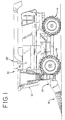
- Figure 1 is a side elevational view of an agricultural combine with a corn header attached to the front end;
- Figure 2 is a perspective view of a portion of a corn head, showing two adjacent row units and a divider that is lifted up to illustrate a support structure;
- Figure 3 is a perspective view of the support structure;
- Figure 4 is a side elevational view of the support structure, showing the support structure in its bottom at rest position;
- Figure 5 is a side elevational view of the support structure, showing the support structure buckled upwards;
- Figure 6 is side elevational view of the support structure, showing the support structure rotated rearwards in a shipping position;
- Figure 7 is a side elevational view of a portion of a corn head, showing the divider and hood lowered in an operating position; and
- Figure 8 is a side elevational view of a portion of a corn head, showing the divider and hood raised in a transport or service position.
-
- Referring now to the drawings, and particularly to Figure 1, there is shown a self-propelled
agricultural combine 10. Thecombine 10 includes abody 12 supported bywheels 14 and an engine (not shown) for driving thewheels 14 to allow thecombine 10 to move from place to place. An operator'sstation 16 is positioned towards the forward end of thecombine body 12 and includes numerous controls to allow the operator to adjust the functions of thecombine 10. - At the forward end of the combine is a
corn harvesting header 18 for stripping ears of corn from the corn stalks. Corn heads 18 are well-known to those skilled in the art ofagricultural combines 10 and only a brief explanation of its operation will be necessary. - Referring now to Figure 2, the
corn header 18 includes a number ofrow units 24 that are usually equally spaced along the width of theheader 18. Eachrow unit 24 thus operates on a single row of corn as thecombine 10 travels through the crop field. Therow units 24 include a set ofstripper plates 26 that are installed on each side of anarrow opening 28. Thenarrow opening 28 extends forward and has a front entrance opening which allows crop stalks to enter thenarrow opening 28 as thecombine 10 travels through the field. A corresponding set of stalk rolls 30 is installed under thestripper plates 26. Each of the stalk rolls 30 includes a cylindrical body (not shown) and a number of spiral vanes (not shown) attached to the exterior of the cylindrical body. The cylindrical body is then rotatably connected to therow unit 24 so that the axis of rotation is generally horizontal and parallel to thenarrow opening 28. - Therefore, when a corn stalk enters the
narrow opening 28, the spiral vanes of the stalk rolls 30 engage the stalk on each side of the row. The stalk rolls 30 are rotatably driven so that the stalks are pulled downward by the stalk rolls 30 through thenarrow opening 28. The width of thenarrow opening 28 is specially sized to allow the stalks to freely travel through theopening 28 but to prevent the corn ears from travelling through theopening 28. Thus, when the ears contact thestripper plates 26 as the corn stalk is being pulled downward, the ear is stripped from the stalk. - A set of gathering
chains 34 then feed the stripped ears rearward. Thegathering chains 34 include a number ofextended fingers 35 that engage and push the loose ears rearward. Each gatheringchain 34 is installed above one of thestripper plates 26. Thus, after thestripper plates 26 separate the ear from the stalk, thegathering chain fingers 35 from each side of thenarrow opening 28 push the ears rearward along the top of thestripper plates 26 towards the gathering conveyor (not shown). The gathering conveyor is a large cylindrical rotating member that extends across the width of thecorn header 18 and includes spiral vanes for engaging the corn ears. The gathering conveyor then feeds the ears to afeeder housing 20 which feeds the ears rearward into thecombine body 12 where the grain is separated from the cobs and the husks. After separation, the grain is stored in anonboard storage bin 22 and the non-grain materials are discharged from the rear end of the combine. - A
divider 38 is provided which travels between the rows of corn and funnels the rows of corn into thenarrow opening 28 as thecombine 10 travels through the field. Thedivider 38 is a sheet metal or plastic shield that extends forward from therow units 24 and has a narrow pointedfront end 39 and a widerrear end 40 that extends between adjacentnarrow openings 28. Along therear end 40 of thedivider 38, thedivider 38 is pivotally attached 37 to ahood 36. Thehood 36 is a shield that extends from therear end 40 of thedivider 38 and along the top side of therow units 24. Thehood 36, thus, protects the top side of therow units 24 from crop debris and directs the stripped corn ears down to thegathering chain fingers 35. - Referring now also to Figures 3 through 6, a
support structure 50 is provided under thedivider 38 for providing vertical and lateral support to thedivider 38. Accordingly, thedivider 38 rests upon thesupport structure 50 through aninterior support cage 42. Thesupport structure 50 is attached to therow units 24 with apivot support member 52 that extends between twoadjacent row units 24. Pivotally attached 53 to thepivot support member 52 are twolongitudinal support members 54 that extend forward beyond therow units 24. At the forward end of thelongitudinal support members 54 is across support member 56 that is fixedly connected to thelongitudinal support members 54. Preferably, thelongitudinal support members 54 and thecross support member 56 are formed from a single U-shaped member. Finally, atension assembly 60 is pivotally attached at A along its rear end to the pivot support member and is pivotally attached at B along its front end to thecross support 56. - The
tension assembly 60 is a multiple piece assembly that includes afirst member 62 and asecond member 64. The rear end of thefirst member 62 is pivotally attached at A to thepivot support member 52, and the front end of thesecond member 64 is pivotally attached at B to thecross support 56. The front end of thefirst member 62 and the rear end of thesecond member 64 are then pivotally attached to each other through apivot pin 66. Astop pin 68 is installed through theclevis 65 of thefirst member 62 and rests against the top side of thesecond member 64 when thesupport structure 50 is in its bottom, at rest position. - The
tension assembly 60 performs several different functions. Thetension assembly 60 resists gravity to support thelongitudinal support members 54 in their bottom, at rest position. Thetension assembly 60 also provides aheight adjustment mechanism 70 for raising or lowering the position of thedivider 38. - In the preferred embodiment, the
height adjustment mechanism 70 is aturnbuckle 70.Turnbuckles 70 are well-known in the art and include oppositely threadedrods 71 that are screwed into opposing ends of theturnbuckle frame 72. Thus, when theturnbuckle frame 72 is turned in one direction thesecond tension member 64 is shortened and is lengthened when theturnbuckle frame 72 is turned in the other direction. Correspondingly, thelongitudinal support members 54 and thedivider 38 raise and lower as theturnbuckle frame 72 is turned. A lockingmember 74 is threaded onto one of therods 71 and can be tightened against theturnbuckle frame 72 in order to resist unwanted vibrational turning of theframe 72. The lockingmember 74 may take the form of a lock nut or may be a specially shapedplate 74 that can be tightened without a wrench. - The
tension assembly 60 buckles upward when an object from the ground is struck by thesupport structure 50. Often combine operators will lower thecorn header 18 and adjust thedividers 38 downward with the turnbuckle 70 so that thesupport structure 50 travels near the ground surface. It is expected in this situation that raised objects from the ground will be frequently struck by the bottom side of thesupport structure 50. The construction of thetension assembly 60 allows thesupport structure 50 to raise up over the underlying objects. To achieve this end thestop pin 68 is positioned to prevent the lines oftension 50 of the first andsecond members first member 62, which extends between its rear pivot connection A and thepivot pin 66, and the line of tension D of thesecond member 64, which extends between its front pivot connection B and thepivot pin 66. This angle E then allows the first andsecond members pivot pin 66 and correspondingly raise thelongitudinal support members 54 when an underlying object is struck. - The rigid first and
second tension members divider 38 is also capable of buckling upwards when an underlying object is struck. However, the chain in these systems becomes loose during buckling and consequently can flop around and become entangled in nearby assemblies. In contrast, thetension members - The apparatus also provides a
clearance opening 76 in the lateral hood support 78 to allow for free movement of thefirst tension member 62. The lateral hood support 78 typically extends between the width of thehood 36 to laterally support the width ofhood 36. Attachingmechanisms 79 may also be provided to fixedly attach the hood support 78, and consequently thehood 36 and thedivider 38, to therow units 24 during harvesting. In the present embodiment the rear connecting point A of thefirst tension member 62 is located behind the lateral hood support 78. Therefore, aclearance opening 76 of sufficient height is provided through the lateral hood support 78 to accommodate the expected upward movement of thefirst tension member 62. In addition to theclearance opening 76, thefirst tension member 62 has been shaped with a downward bend away from the line of tension C to also provide clearance. Thus in the preferred embodiment, 60 mm of clearance is provided between the lateral hood support 78 and thefirst tension member 62. Accordingly, the height of theclearance opening 76 is about 80 mm. Thetop surface 63 of thefirst tension member 62 is also bent downward about 12 mm from the line of tension C. - Referring now to Figures 2, 7, and 8, a
retention pin 80 is provided at the front end of thesupport structure 50 for shortening the extended length of thedivider 38 and raising thehood 36 and thedivider 38 from therow units 24. This feature is provided to minimise the collision hazard presented by the long, forward extendingdividers 38 during transport. In addition, a secure service position of thehood 36 and thedivider 38 is provided. Therefore, areceiver 82 is also provided at theforward end 39 of thedivider 38. Aretention hole 84 is provided through thereceiver 82 for receiving theretention pin 80. Thus, by unlocking the attachingmechanisms 79 and raising thepivot connection 37 between thehood 36 and thedivider 38, thefront end 39 of thedivider 38 can be relocated rearward and locked into place with theretention pin 80 andhole 84. Thefront end 39 of thedivider 38 then rests betweenextended arms 55 that support theretention pin 80. The extended length of thedivider 38 therefore is substantially reduced. - As is also readily apparent from these Figures, the
row unit 24 can be easily accessed and serviced when thehood 36 anddivider 38 are raised in this position. Theretention pin 80 thus securely retains thehood 36 and thedivider 38 in this raised position to prevent them from falling while a person is working underneath. - Referring now to Figure 6, the
support structure 50 can also be repositioned to provide a compact package during shipping of thecorn header 18. In this application thedivider 38 is disconnected from thesupport structure 50 and shipped unattached. The rear connecting point A of thefirst tension member 62 is then disconnected to allow thelongitudinal support members 54 to freely rotate around theirpivot connections 53. This allows thesupport structure 50 to be rotated around so that thesupport structure 50 is facing rearward instead of forward. Thus in this rearward shipping position, thesupport structure 50 no longer extends beyond the forward end of therow units 24. Thetension assembly 60 can then be secured in place by either strapping theassembly 60 down with appropriate shipping materials, or preferably, the rear end of thefirst tension member 62 is reconnected to its connecting point A. - While a preferred embodiment of the invention has been described, it should be understood that the invention is not so limited, and modifications may be made without departing from the invention. The scope of the invention is defined by the appended claims, and all devices that come within the meaning of the claims, either literally or by equivalence, are intended to be embraced therein.
Claims (16)
- A header (18) for an agricultural harvesting machine (10) comprising:characterised in that said yieldable support means (50) comprise a buckling system (60) comprising a first member (62) connected by a first pivotal attachment (A) to at least one row unit (24) and a second member(64) connected by a second pivotal attachment (66) to said first member (62).a plurality of row units (24);at least one divider (38) pivotally connected to said row units (24); andyieldable support means (50) for sustaining said divider (38) in an operating position while allowing movement of said divider (38) when striking ground objects,
- A header according to claim 1, characterised in that said buckling system (60) further comprises:a support member (54,56) having one end connected by a third pivotal attachment (53) to said at least one row unit and an opposite end connected by a fourth pivotal attachment (B) to said second member (64); anda stop (68) for preventing the alignment of the line of tension (C) extending between said first pivotal attachment (A) and said second pivotal attachment (66) with the line of tension (D) extending between said third pivotal attachment (53) and said fourth pivotal attachment (B).
- A header according to claim 2, characterised in that the angle (E) between said lines of tension (C,D) is substantially equal to 10° when said stop (68) is engaged.
- A header according to any of the preceding claims, characterised in that it further comprises a transverse support (78) for supporting the width of a crop shield (36), said support being provided with a clearance opening (76) for providing travel clearance for said first member (62) and/or said second member (64).
- A header according to claim 4, characterised in that said transverse support (78) is located above said first member (62) and said clearance opening is substantially equal to 80 mm in height.
- A header according to any of the preceding claims, characterised in that said first member (62) has a bended shape for providing travel clearance between a transverse support and said first member (62).
- A header according to claim 6, characterised in that said first member (62) has a downward bended shape such that a top surface of said first member (62) is substantially 12 mm below the line of tension (C) extending between said first pivotal attachment (A) and said second pivotal attachment (66).
- A header according to any of the preceding claims, characterised in that said second member (64) comprises a height adjustment mechanism (70) that is capable of providing infinite adjustments between a maximum height and a minimum height.
- A header according to claim 8, characterised in that said height adjustment mechanism is a turnbuckle (70).
- A header according to claim 8 or 9, characterised in that said support means (50) further comprise a locking member (74) for tightening against said height adjustment mechanism (70).
- A header according to any of the preceding claims, characterised in that said support means (50) comprise a support member (54,56) having one end connected to said at least one row unit for supporting said at least one divider (38) in both an operating and a transport or service position.
- A header according to claim 11, characterised in that it comprises a crop shield (36) having one end pivotally connected to said row units (24) and an opposite end connected by a further pivotal connection (37) to said at least one divider (38) allowing the raising up of said connection (37) to said transport or service position.
- A header according to claim 11 or 12, characterised in that said support means (50) comprise a first locking member (80) and said divider (38) comprise a second locking member (84) for locking said divider (38) in said transport or service position.
- A header according to claim 13, characterised in that said first locking member is a retention pin (80) and said second locking member is a retention hole (84).
- A header according to any of the claims 11 to 14, characterised in that :said support member (54,56) has one end connected to said at least one row unit by a third pivotal attachment (53); andsaid first pivotal attachment (A) is releasable for allowing disconnection of said first member (62) from said at least one row unit (24) and rotation of said support member (54,56) from a forward operating position in a retracted shipping position in which no portion of the support member (54,56) extends beyond a front end of a row unit.
- A header according to claim 15, characterised in that in said shipping position said first pivotal attachment (A) is reconnected to said at least one row unit (24).
Applications Claiming Priority (2)
| Application Number | Priority Date | Filing Date | Title |
|---|---|---|---|
| US09/658,402 US6513313B1 (en) | 2000-09-08 | 2000-09-08 | Support structure for a divider of an agricultural corn head |
| US658402 | 2000-09-08 |
Publications (2)
| Publication Number | Publication Date |
|---|---|
| EP1186223A1 true EP1186223A1 (en) | 2002-03-13 |
| EP1186223B1 EP1186223B1 (en) | 2004-11-17 |
Family
ID=24641101
Family Applications (1)
| Application Number | Title | Priority Date | Filing Date |
|---|---|---|---|
| EP01203368A Expired - Lifetime EP1186223B1 (en) | 2000-09-08 | 2001-09-06 | Support structure for a divider of an agricultural corn head. |
Country Status (4)
| Country | Link |
|---|---|
| US (1) | US6513313B1 (en) |
| EP (1) | EP1186223B1 (en) |
| AT (1) | ATE282297T1 (en) |
| DE (1) | DE60107171T2 (en) |
Cited By (3)
| Publication number | Priority date | Publication date | Assignee | Title |
|---|---|---|---|---|
| EP1688030A1 (en) * | 2005-02-08 | 2006-08-09 | Deere & Company | Divider for agricultural header |
| EP2524589A1 (en) * | 2011-05-20 | 2012-11-21 | Deere & Company | Cornhead divider lift assist linkage |
| US11375666B2 (en) | 2017-01-17 | 2022-07-05 | Cnh Industrial America Llc | Corn header adjustable divider point |
Families Citing this family (20)
| Publication number | Priority date | Publication date | Assignee | Title |
|---|---|---|---|---|
| BRPI0700408B1 (en) * | 2006-02-17 | 2016-04-19 | Deere & Co | tip and cap assembly for a row crop head |
| US20080092507A1 (en) * | 2006-10-18 | 2008-04-24 | Dragotec Usa, Inc. | Corn head with tension control for deck plates |
| US20100071336A1 (en) * | 2008-09-23 | 2010-03-25 | Timothy Franklin Christensen | Sprockets And Chains For A Row Unit |
| US20110047949A1 (en) * | 2009-09-02 | 2011-03-03 | Oxbo International Corp. | Double tapered knife rolls |
| US8141331B2 (en) | 2010-04-20 | 2012-03-27 | Cnh America Llc | Divider support apparatus with integral adjustable torsional preload mechanism and vibration damper |
| US9253944B2 (en) * | 2012-11-12 | 2016-02-09 | Dragotec Usa, Inc. | Snout height and tension adjustment |
| US9032700B2 (en) | 2013-03-13 | 2015-05-19 | Agco Corporation | Folding divider assembly for corn header and method of operation |
| US9226447B2 (en) | 2013-11-01 | 2016-01-05 | Cnh Industrial America Llc | End divider for a header of an agricultural harvester |
| BE1021401B1 (en) * | 2014-09-03 | 2015-11-16 | Cnh Industrial Belgium Nv | FOLDING PLANT MOWER |
| US9532505B2 (en) | 2014-12-24 | 2017-01-03 | Cnh Industrial America Llc | Hood divider adjustment apparatus for an agricultural harvester |
| US9642307B2 (en) * | 2015-05-08 | 2017-05-09 | Cnh Industrial America Llc | Header end hood mount for an agricultural harvester |
| US10172286B2 (en) | 2016-01-06 | 2019-01-08 | Oxbo International Corporation | Knife rolls with differing lengths |
| US10694654B2 (en) * | 2018-01-29 | 2020-06-30 | Cnh Industrial America Llc | Automatic divider height positioning for an agricultural harvester |
| US10897846B2 (en) * | 2018-10-31 | 2021-01-26 | Deere & Company | Corn harvester |
| US12052951B2 (en) * | 2018-11-06 | 2024-08-06 | Cnh Industrial America Llc | Remotely adjustable row divider for an agricultural harvester |
| US11032969B2 (en) * | 2019-04-11 | 2021-06-15 | Cnh Industrial America Llc | Crop divider for a corn header |
| US11234371B2 (en) * | 2019-08-07 | 2022-02-01 | Cnh Industrial America Llc | Tool-less folding divider for combine head |
| US11570950B2 (en) * | 2020-07-17 | 2023-02-07 | Deere & Company | Folding harvester with crop divider lift and frame lock |
| US12610888B2 (en) * | 2022-10-28 | 2026-04-28 | Deere & Company | Retractable crop divider of an agricultural header |
| DE102023116238A1 (en) | 2023-06-21 | 2024-12-24 | Claas Hungaria Kft. | Attachment for harvesting crops standing in rows |
Citations (5)
| Publication number | Priority date | Publication date | Assignee | Title |
|---|---|---|---|---|
| US4227368A (en) * | 1979-07-18 | 1980-10-14 | Deere & Company | Gatherer sheet arrangement for a row crop harvesting header |
| US4446682A (en) * | 1980-12-20 | 1984-05-08 | Claas Ohg | Agricultural attachment for harvesting agricultural products arranged in rows |
| US4538404A (en) * | 1983-08-16 | 1985-09-03 | General Dryer Corporation | Adjustable crop divider apparatus |
| EP0848898A1 (en) * | 1996-12-17 | 1998-06-24 | New Holland Belgium N.V. | Plastic divider assembly with frame for a corn harvester |
| US6247297B1 (en) * | 1999-08-20 | 2001-06-19 | Case Corporation | Jackknife support system for a combine cornhead |
Family Cites Families (3)
| Publication number | Priority date | Publication date | Assignee | Title |
|---|---|---|---|---|
| US4493181A (en) * | 1984-05-14 | 1985-01-15 | Farmer's Factory Co. | Attachment for the snouts of combines and the like |
| EP0215142B1 (en) * | 1985-09-14 | 1990-06-06 | Deere & Company | Crop divider for agricultural machines |
| US5253717A (en) * | 1992-01-30 | 1993-10-19 | Case Corporation | Foldable agricultural implement |
-
2000
- 2000-09-08 US US09/658,402 patent/US6513313B1/en not_active Expired - Fee Related
-
2001
- 2001-09-06 AT AT01203368T patent/ATE282297T1/en not_active IP Right Cessation
- 2001-09-06 DE DE60107171T patent/DE60107171T2/en not_active Expired - Lifetime
- 2001-09-06 EP EP01203368A patent/EP1186223B1/en not_active Expired - Lifetime
Patent Citations (5)
| Publication number | Priority date | Publication date | Assignee | Title |
|---|---|---|---|---|
| US4227368A (en) * | 1979-07-18 | 1980-10-14 | Deere & Company | Gatherer sheet arrangement for a row crop harvesting header |
| US4446682A (en) * | 1980-12-20 | 1984-05-08 | Claas Ohg | Agricultural attachment for harvesting agricultural products arranged in rows |
| US4538404A (en) * | 1983-08-16 | 1985-09-03 | General Dryer Corporation | Adjustable crop divider apparatus |
| EP0848898A1 (en) * | 1996-12-17 | 1998-06-24 | New Holland Belgium N.V. | Plastic divider assembly with frame for a corn harvester |
| US6247297B1 (en) * | 1999-08-20 | 2001-06-19 | Case Corporation | Jackknife support system for a combine cornhead |
Cited By (5)
| Publication number | Priority date | Publication date | Assignee | Title |
|---|---|---|---|---|
| EP1688030A1 (en) * | 2005-02-08 | 2006-08-09 | Deere & Company | Divider for agricultural header |
| US7240471B2 (en) | 2005-02-08 | 2007-07-10 | Deere & Company | Row divider having a variable-height ear saver |
| EP2524589A1 (en) * | 2011-05-20 | 2012-11-21 | Deere & Company | Cornhead divider lift assist linkage |
| US8387352B2 (en) | 2011-05-20 | 2013-03-05 | Deere & Company | Cornhead divider lift assist linkage |
| US11375666B2 (en) | 2017-01-17 | 2022-07-05 | Cnh Industrial America Llc | Corn header adjustable divider point |
Also Published As
| Publication number | Publication date |
|---|---|
| ATE282297T1 (en) | 2004-12-15 |
| DE60107171T2 (en) | 2005-04-14 |
| EP1186223B1 (en) | 2004-11-17 |
| US6513313B1 (en) | 2003-02-04 |
| DE60107171D1 (en) | 2004-12-23 |
Similar Documents
| Publication | Publication Date | Title |
|---|---|---|
| EP1186223B1 (en) | Support structure for a divider of an agricultural corn head. | |
| US6247297B1 (en) | Jackknife support system for a combine cornhead | |
| US5195309A (en) | Plastic crop dividers for a row crop header | |
| US5444968A (en) | Outboard crop divider structure guard assembly | |
| US4538404A (en) | Adjustable crop divider apparatus | |
| US7752829B1 (en) | Auger stripper arrangement for corn head | |
| US7591127B1 (en) | Grain harvester header with air assist | |
| EP2018802B1 (en) | Tilt out corn head fender | |
| EP3573445B1 (en) | Corn header adjustable divider point | |
| US20220000029A1 (en) | Remotely adjustable row divider for an agricultural harvester | |
| EP3613274B1 (en) | Corn header row unit | |
| US5960618A (en) | Row unit crop guide for harvesting multiple rows | |
| US20160278290A1 (en) | Harvester Header | |
| US6901730B1 (en) | End hood extension for a corn header | |
| EP0861583A1 (en) | Corn header auger trough divider. | |
| US20030110752A1 (en) | Guard for crop pick up apparatus | |
| US6032445A (en) | Combine header grain catch pans | |
| EP2862433A1 (en) | Row divider for a corn header of a combine harvester | |
| US8621835B2 (en) | Trash finger | |
| EP4346369B1 (en) | Multi-segment header for an agricultural harvester | |
| KR101712128B1 (en) | Cutting device for combines | |
| US20050120694A1 (en) | Universal corn head mounting system | |
| CA1085627A (en) | Rock guard for a row crop harvesting machine | |
| EP4353062A1 (en) | Impact sensing systems and methods for an agricultural header | |
| US6272824B1 (en) | Header transport lower rest bracket assembly |
Legal Events
| Date | Code | Title | Description |
|---|---|---|---|
| PUAI | Public reference made under article 153(3) epc to a published international application that has entered the european phase |
Free format text: ORIGINAL CODE: 0009012 |
|
| AK | Designated contracting states |
Kind code of ref document: A1 Designated state(s): AT BE CH CY DE DK ES FI FR GB GR IE IT LI LU MC NL PT SE TR |
|
| AX | Request for extension of the european patent |
Free format text: AL;LT;LV;MK;RO;SI |
|
| 17P | Request for examination filed |
Effective date: 20020905 |
|
| AKX | Designation fees paid |
Free format text: AT BE CH CY DE DK ES FI FR GB GR IE IT LI LU MC NL PT SE TR |
|
| RAP1 | Party data changed (applicant data changed or rights of an application transferred) |
Owner name: CNH BELGIUM N.V. |
|
| GRAP | Despatch of communication of intention to grant a patent |
Free format text: ORIGINAL CODE: EPIDOSNIGR1 |
|
| GRAS | Grant fee paid |
Free format text: ORIGINAL CODE: EPIDOSNIGR3 |
|
| GRAA | (expected) grant |
Free format text: ORIGINAL CODE: 0009210 |
|
| AK | Designated contracting states |
Kind code of ref document: B1 Designated state(s): AT BE CH CY DE DK ES FI FR GB GR IE IT LI LU MC NL PT SE TR |
|
| PG25 | Lapsed in a contracting state [announced via postgrant information from national office to epo] |
Ref country code: AT Free format text: LAPSE BECAUSE OF FAILURE TO SUBMIT A TRANSLATION OF THE DESCRIPTION OR TO PAY THE FEE WITHIN THE PRESCRIBED TIME-LIMIT Effective date: 20041117 Ref country code: LI Free format text: LAPSE BECAUSE OF FAILURE TO SUBMIT A TRANSLATION OF THE DESCRIPTION OR TO PAY THE FEE WITHIN THE PRESCRIBED TIME-LIMIT Effective date: 20041117 Ref country code: TR Free format text: LAPSE BECAUSE OF FAILURE TO SUBMIT A TRANSLATION OF THE DESCRIPTION OR TO PAY THE FEE WITHIN THE PRESCRIBED TIME-LIMIT Effective date: 20041117 Ref country code: FI Free format text: LAPSE BECAUSE OF FAILURE TO SUBMIT A TRANSLATION OF THE DESCRIPTION OR TO PAY THE FEE WITHIN THE PRESCRIBED TIME-LIMIT Effective date: 20041117 Ref country code: CH Free format text: LAPSE BECAUSE OF FAILURE TO SUBMIT A TRANSLATION OF THE DESCRIPTION OR TO PAY THE FEE WITHIN THE PRESCRIBED TIME-LIMIT Effective date: 20041117 Ref country code: BE Free format text: LAPSE BECAUSE OF FAILURE TO SUBMIT A TRANSLATION OF THE DESCRIPTION OR TO PAY THE FEE WITHIN THE PRESCRIBED TIME-LIMIT Effective date: 20041117 Ref country code: NL Free format text: LAPSE BECAUSE OF FAILURE TO SUBMIT A TRANSLATION OF THE DESCRIPTION OR TO PAY THE FEE WITHIN THE PRESCRIBED TIME-LIMIT Effective date: 20041117 |
|
| REG | Reference to a national code |
Ref country code: GB Ref legal event code: FG4D |
|
| REG | Reference to a national code |
Ref country code: CH Ref legal event code: EP |
|
| REG | Reference to a national code |
Ref country code: IE Ref legal event code: FG4D |
|
| REF | Corresponds to: |
Ref document number: 60107171 Country of ref document: DE Date of ref document: 20041223 Kind code of ref document: P |
|
| PG25 | Lapsed in a contracting state [announced via postgrant information from national office to epo] |
Ref country code: DK Free format text: LAPSE BECAUSE OF FAILURE TO SUBMIT A TRANSLATION OF THE DESCRIPTION OR TO PAY THE FEE WITHIN THE PRESCRIBED TIME-LIMIT Effective date: 20050217 Ref country code: SE Free format text: LAPSE BECAUSE OF FAILURE TO SUBMIT A TRANSLATION OF THE DESCRIPTION OR TO PAY THE FEE WITHIN THE PRESCRIBED TIME-LIMIT Effective date: 20050217 Ref country code: GR Free format text: LAPSE BECAUSE OF FAILURE TO SUBMIT A TRANSLATION OF THE DESCRIPTION OR TO PAY THE FEE WITHIN THE PRESCRIBED TIME-LIMIT Effective date: 20050217 |
|
| PG25 | Lapsed in a contracting state [announced via postgrant information from national office to epo] |
Ref country code: ES Free format text: LAPSE BECAUSE OF FAILURE TO SUBMIT A TRANSLATION OF THE DESCRIPTION OR TO PAY THE FEE WITHIN THE PRESCRIBED TIME-LIMIT Effective date: 20050228 |
|
| NLV1 | Nl: lapsed or annulled due to failure to fulfill the requirements of art. 29p and 29m of the patents act | ||
| REG | Reference to a national code |
Ref country code: CH Ref legal event code: PL |
|
| ET | Fr: translation filed | ||
| PG25 | Lapsed in a contracting state [announced via postgrant information from national office to epo] |
Ref country code: CY Free format text: LAPSE BECAUSE OF FAILURE TO SUBMIT A TRANSLATION OF THE DESCRIPTION OR TO PAY THE FEE WITHIN THE PRESCRIBED TIME-LIMIT Effective date: 20050906 Ref country code: IE Free format text: LAPSE BECAUSE OF NON-PAYMENT OF DUE FEES Effective date: 20050906 |
|
| PLBE | No opposition filed within time limit |
Free format text: ORIGINAL CODE: 0009261 |
|
| STAA | Information on the status of an ep patent application or granted ep patent |
Free format text: STATUS: NO OPPOSITION FILED WITHIN TIME LIMIT |
|
| PG25 | Lapsed in a contracting state [announced via postgrant information from national office to epo] |
Ref country code: MC Free format text: LAPSE BECAUSE OF NON-PAYMENT OF DUE FEES Effective date: 20050930 Ref country code: LU Free format text: LAPSE BECAUSE OF NON-PAYMENT OF DUE FEES Effective date: 20050930 |
|
| 26N | No opposition filed |
Effective date: 20050818 |
|
| REG | Reference to a national code |
Ref country code: IE Ref legal event code: MM4A |
|
| PG25 | Lapsed in a contracting state [announced via postgrant information from national office to epo] |
Ref country code: PT Free format text: LAPSE BECAUSE OF NON-PAYMENT OF DUE FEES Effective date: 20050417 |
|
| REG | Reference to a national code |
Ref country code: DE Ref legal event code: R082 Ref document number: 60107171 Country of ref document: DE Representative=s name: G. KOCH UND KOLLEGEN, DE |
|
| REG | Reference to a national code |
Ref country code: DE Ref legal event code: R082 Ref document number: 60107171 Country of ref document: DE Representative=s name: G. KOCH UND KOLLEGEN, DE Effective date: 20140428 Ref country code: DE Ref legal event code: R081 Ref document number: 60107171 Country of ref document: DE Owner name: CNH INDUSTRIAL BELGIUM NV, BE Free format text: FORMER OWNER: CNH BELGIUM NV, ZEDELGEM, BE Effective date: 20140428 |
|
| REG | Reference to a national code |
Ref country code: FR Ref legal event code: CD Owner name: CNH INDUSTRIAL BELGIUM NV Effective date: 20140725 |
|
| REG | Reference to a national code |
Ref country code: DE Ref legal event code: R084 Ref document number: 60107171 Country of ref document: DE |
|
| REG | Reference to a national code |
Ref country code: GB Ref legal event code: 746 Effective date: 20160613 Ref country code: FR Ref legal event code: PLFP Year of fee payment: 16 |
|
| REG | Reference to a national code |
Ref country code: FR Ref legal event code: PLFP Year of fee payment: 17 |
|
| PGFP | Annual fee paid to national office [announced via postgrant information from national office to epo] |
Ref country code: FR Payment date: 20170628 Year of fee payment: 17 |
|
| PGFP | Annual fee paid to national office [announced via postgrant information from national office to epo] |
Ref country code: DE Payment date: 20170706 Year of fee payment: 17 Ref country code: GB Payment date: 20170703 Year of fee payment: 17 Ref country code: IT Payment date: 20170905 Year of fee payment: 17 |
|
| REG | Reference to a national code |
Ref country code: DE Ref legal event code: R119 Ref document number: 60107171 Country of ref document: DE |
|
| GBPC | Gb: european patent ceased through non-payment of renewal fee |
Effective date: 20180906 |
|
| PG25 | Lapsed in a contracting state [announced via postgrant information from national office to epo] |
Ref country code: DE Free format text: LAPSE BECAUSE OF NON-PAYMENT OF DUE FEES Effective date: 20190402 Ref country code: IT Free format text: LAPSE BECAUSE OF NON-PAYMENT OF DUE FEES Effective date: 20180906 |
|
| PG25 | Lapsed in a contracting state [announced via postgrant information from national office to epo] |
Ref country code: FR Free format text: LAPSE BECAUSE OF NON-PAYMENT OF DUE FEES Effective date: 20180930 |
|
| PG25 | Lapsed in a contracting state [announced via postgrant information from national office to epo] |
Ref country code: GB Free format text: LAPSE BECAUSE OF NON-PAYMENT OF DUE FEES Effective date: 20180906 |